Abstract
This work presents the use of a three-element radiating structure for circularly polarized Low-Power Wide Area Network (LP-WAN) communication with space. The proposed structure has a 72 mm × 72 mm × 12 mm compact size with Right-Handed Circular Polarization (RHCP) and a 120 wide beamwidth radiation pattern. Printed on low-cost FR4 Epoxy substrate, a feeding network circuit based on Quasi Lumped Quadrature Coupler (QLQC), it achieves a −0.6 dB insertion loss and a very compact size. The final structure has a 69% total efficiency and a 3.14 dBic realized gain.
1. Introduction
In the last decade, Low Power Wide Area Network (LPWAN) technology came out as a perfect choice for enabling longer range connections at a lower cost and more efficient power consumption [1]. The number of connected objects is expected to reach 41.6 billion in 2025 [2]. Several Internet of Things (IoT) use cases must be deployed in isolated areas without any mobile terrestrial coverage or other forms of connectivity. In this context, satellite communication becomes a crucial enabler to deploy IoT connectivity all over the world [3]. On the basis of this idea, several projects are developing an IoT solution that provides a connecting link between the nodes on earth and a constellation of low earth orbit (LEO) CubeSat satellites.
To deploy such a scenario, a terrestrial antenna with specifications such as a compact size, high efficiency, and low cost are needed [4]. In order to avoid polarization mismatch losses between the devices and the satellite, which are caused by their dissimilar orientations, circular polarization (CP) is preferred. Many solutions have been proposed in the literature to provide a wide-angle CP radiation pattern [5]. Several designs based on a single port and slot structure have been developed for Global Positioning (GPS) applications. In [6], a CPW-fed slot antenna was designed with a square slot shape fed by a halberd-shaped metal strip. The antenna showed a good axial ratio lower than 3 dB in the 1545–1605 MHz frequency band, but the design required a complex parametric study.
The uses of the specific characteristics of the electromagnetic wave in ferrite materials have been used to generate CP using non-reciprocity phenomenon in [7]. The antenna design is based on the classical patch structure. Nonetheless, the author proposed to use the ferrite material as the substrate. Miniaturization is also naturally obtained thanks to the high permittivity and permeability of such material. However, the cost and associated loss of this material are the limitations for the low-cost application.
Several solutions based on degenerate orthogonal dual-mode patch antenna are presented in [8]. These proposed solutions are extensively used for GPS applications. However, such a structure needs a high permittivity substrate such as ceramic for miniaturization, which increases the production cost. A compact folded patch was proposed in [9] with an impedance bandwidth of 2.1% and a 3-dB axial-ratio (AR) bandwidth of about 0.76%. By using the stacked configuration, several layers are placed on the ground plane of 100 mm diameter. This antenna, excited by a single port located in the patch corner is very sensitive to any fabrication errors.
As previously shown, the single port structure has several limitations which could be overcome by using the multiple-port approach. Of course, the use of several ports will imply the use of an additional circuit to generate the right signal of each port (amplitude and phase). The use of a dual port square patch antenna has been used for many decades [10], but the miniaturization still requires a high permittivity ceramic substrate. In order to ensure a wide and stable radiation pattern and strong miniaturization, the axis of symmetry is required. Some compact solutions with four elements have also been studied with a wide radiation pattern [11,12,13,14]. However, the proposed structures in these references use the low-loss dielectric substrates, which are expensive for industrial application. To solve this cost problem, the antenna in [15] is fabricated on FR4-Epoxy, which is a low-cost material. Nonetheless, due to the high-loss substrate, this design provides a dBic gain at 915 MHz.
In this paper, we propose to study a terrestrial compact antenna for LPWAN space communication on a low-cost substrate. The use of a 3-element structure has the potential to provide better performance over a 4-element structure, as shown in [16]. Until now, a 3-element approach has not been widely used, due to the difficulty of designing a low-loss feeding network. In the next sections, by using Ansoft HFSS EM solver, a 3-element structure is designed and a new compact feeding circuit is proposed. The structure also includes a large ground plane over the entire bottom of the substrate to ease the integration of electronic components and batteries. In terms of the frequency band, 868 MHz is targeted with an 8 MHz bandwidth. Considering a Low-Earth-Orbit satellite constellation, a wide angle radiation pattern is desired to enable communication with the satellite even at a low-elevation angle.
2. Antenna Design and Simulations
2.1. Radiating Elements
The 3-element configuration will require to split the power into three equi-amplitude signals with 0, 120, and 240 phase shifts. The proposed structure is composed of three identical elements that are symmetrically placed around a central axis. A ground plane with a disk or triangular shape is by nature more suitable for this solution. The disk form is preferred in order to maximize the antenna frequency bandwidth. Then, the antennas are built on a top PCB, as shown in Figure 1. By using a vertical Inverted F antenna structure, these radiating elements are placed on the edges of the disc with the feeding lines coming from the disk center. The top layer is connected to the ground plane at the bottom layer by 1mm diameter metal wires.
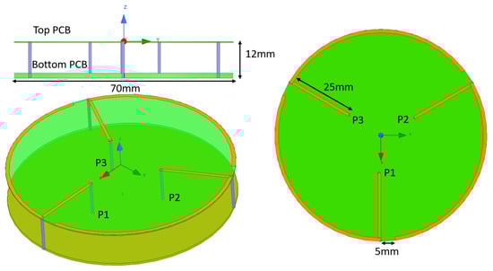
Figure 1.
Top, side, and 3D view of the radiating structure.
The antenna is simulated and optimized with a 3D EM solver. S-parameters are plotted on Figure 2. For clarity and considering the structure symmetry, only and are presented. A maximum coupling between the feeding ports of −8 dB is simulated. Considering that the three feeding ports are fed with a 120 phase shift, power will be dissipated, due to the coupling. Nevertheless, the loss will depend on the way the two coupled signals will be recombined at the third port.
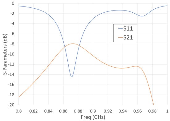
Figure 2.
Simulated S-parameters of the proposed radiating elements.
In order to generate three RF signals with a 120 phase shift, a compact circuit based on a hybrid coupler is proposed (Figure 3). One-third of the signal will be reflected from the direct and coupled port of the coupler by using a simple reactive load, and the reflected signal will recombine constructively in the coupler isolated port, thus providing three equal amplitude outputs. In order to get the required phase shift, additional delay lines are needed on each port access.
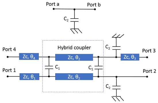
Figure 3.
Feeding circuit schematic.
The hybrid coupler circuit is based on a quasi-lumped quadrature coupler (QLQC), which is composed of two 45 transmission lines () and two capacitors , which enable strong miniaturization and lower loss compared with a classical branch-line coupler [17]. For a QLQC, the phase of the direct port and coupled port are respectively −90 and 0. On the direct and coupled port of the QLQC, shunt capacitors are connected to reflect a part of the signals. The reflected signals combine constructively on Port 1. The reflection on the shunt capacitor is given by Equation (1)
The value of capacitor is chosen to reflect one-third of the signal at 868 MHz; thus a capacitance of 5.1 pF is required and it provides a reflection phase of 124. Transmission of the QLQC is extracted from [18]. Phase at 868 MHz is −34. Phase at 868 MHz is −124. is tuned to provide a −30 phase shift at 868 MHz. From Equation (2), must provide a phase shift of −57. A feeding line ( = −30) is also added on port 4 to access to the coupler
The circuit is designed in a very compact way with meandered lines on a 1.6 mm-thick FR4 substrate ( and ) as shown in Figure 4. S-parameters results are presented in Figure 5. A perfect circuit would provide an equal amplitude of −4.7 dB on each port and a 120 phase shifts at 868 MHz. A level of −5.3 dB is obtained at 870 MHz, corresponding to a 0.6 dB insertion loss. Considering an amplitude imbalance of 1 dB, a 35 MHz bandwidth is observed. Considering a phase imbalance of 5, an 87 MHz (10 %) frequency bandwidth is obtained.
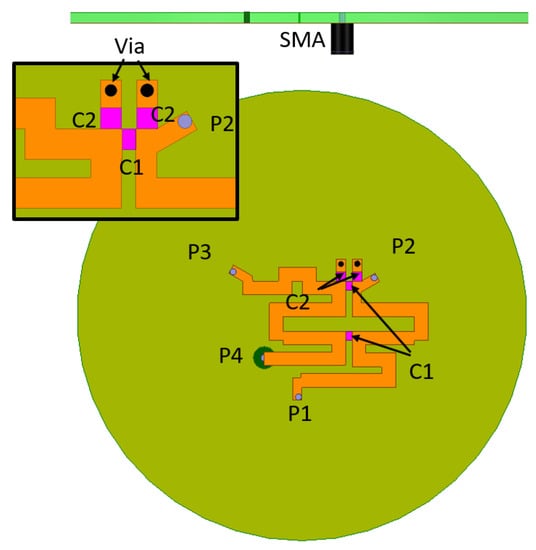
Figure 4.
Top and side of the feeding circuit.
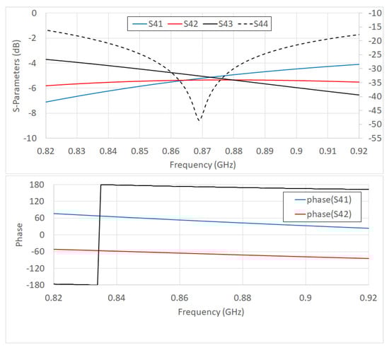
Figure 5.
Phase and amplitude simulation of feeding circuit S-parameters.
2.2. Tri-Fillar Antenna with Proposed Feeding System
Thanks to the studies in the previous sections, the final structure consists of a tri-fillar antenna and a feeding network. The simulated total efficiency of the CP mode is 69% ( −1.5 dB) at 868 MHz. From the different models with and without losses described in Table 1, it is possible to find that 0.65 dB are due to dielectric loss and 0.7 dB to conductivity loss.

Table 1.
Loss origins for the proposed structure.
Furthermore, the radiation features of the antenna are also observed, as shown in Figure 6. The results present the peak realized gain of 3.2 dBic. The axial ratio (AR) decrease to 1 dB at 868 MHz and 20 MHz 3-dB AR bandwidth is obtained from 864 MHz to 884 MHz. Finally, the simulated Left-Handed Circularly Polarized (LHCP) and Right-Handed Circularly Polarized (RHCP) Realized Gain is plotted on Figure 7 for phi = 0 and 90. The −3 dB beamwidth of 117 is obtained.
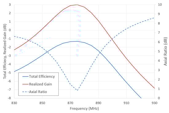
Figure 6.
Realized gain, total efficiency, and axial ratio versus frequency.
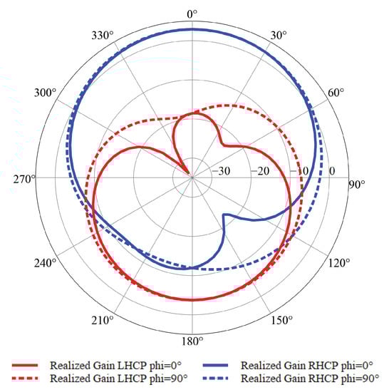
Figure 7.
Simulated Left-Handed Circularly Polarized (LHCP) and Right-Handed Circularly Polarized (RHCP) Gain versus theta for phi = 0 and 90.
3. Prototyping and Measurements
3.1. Prototype Fabrication
The proposed concept has been fabricated on a low cost substrate that is 1.6 mm-thick FR4 Epoxy with the and . The different views of the antenna are shown in Figure 8. The radiating elements are placed at the top board that connect to the feeding circuit and the ground plane at six points by using the 1mm diameter metallic wires. The three inner points link to the three output ports of feeding circuit, while the three outer points are shorted to the ground plane.
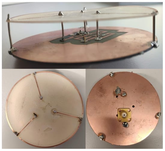
Figure 8.
Picture of the prototype.
3.2. Antenna Measurements
The reflection coefficient of the prototype was measured. A comparison with the simulation in Figure 9 shows a small disagreement. Because of the fabrication issue, the bandwidth of the measurement results was much smaller than the simulation. However, considering a −10 dB S11 criteria, a 27 MHz frequency bandwidth from 860 to 887 MHz was obtained that is suitable for the application. The 3D radiation pattern was measured using near-field StarLab station from Satimo. The antenna had a total efficiency of −1.7 dB at 868 MHz, as presented in Figure 10. The measurement shows a peak RHCP gain of 3 dBic at 868 MHz and a 50 MHz (844–894 MHz) −3 dB RHCP Gain frequency bandwidth. Moreover, a 14 MHz −3 dB axial ratio bandwidth was obtained in the broadside direction. Finally, the radiation pattern at 868 MHz presented in Figure 11 confirms that a −3 dB beamwidth of 117 was obtained.
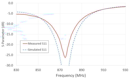
Figure 9.
Simulated and measured reflection coefficient of the complete system.
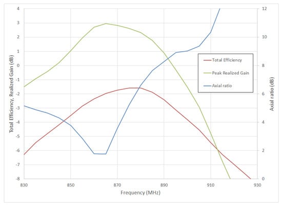
Figure 10.
Total efficiency, peak RHCP Gain, and broadside axial ratio versus frequency.

Figure 11.
Measured LHCP and RHCP Gain versus theta for phi = 0 and 90.
4. Conclusions
A comparison with a 4-element antenna available in the state-of-the-art is summarized in Table 2. As expected, the proposed work provides a better performance in RHCP gain and bandwidth for a smaller maximal dimension. It should also be noted that the use of a higher cost and lower-loss material (tan = 0.001) would increase the antenna gain by 0.6dB. Despite the use of a higher loss FR4 substrate, the proposed solution was successfully used to communicate with the LS1 LEO satellite from Lacuna [19] over a 617 km distance with 14 dBm output power.
Table 2.
Performance comparison with the state-of-the-art.
Author Contributions
Conceptualization, F.F.; methodology, F.F. and L.H.T.; software, F.F.; validation, L.H.T. and F.F.; formal analysis, F.F.; investigation, N.V.T.; resources, F.F.; data curation, L.H.T.; writing—original draft preparation, F.F.; writing—review and editing, L.H.T.; visualization, L.H.T.; supervision, F.F.; All authors have read and agreed to the published version of the manuscript.
Funding
This research is funded by Graduate University of Science and Technology under grant number GUST.STS.DT2017-TT01.
Acknowledgments
This research is funded by Graduate University of Science and Technology under grant number GUST.STS.DT2017-TT01. The CREMANT is acknowledged for support on radiation measurements. Lacuna is deeply thanked for the experiment using the LS1 satellite.
Conflicts of Interest
The authors declare no conflict of interest.
References
- Raza, U.; Kulkarni, P.; Sooriyabandara, M. Low Power Wide Area Networks: An Overview. IEEE Commun. Surv. Tutor. 2017, 19, 855–873. [Google Scholar] [CrossRef]
- MacGillivray, C.; Reinsel, D. Worldwide Global DataSphere IoT Device and Data Forecast; 2019–2023 (IDC # US45066919); International Data Corporation: Framingham, MA, USA, 2019. [Google Scholar]
- Sanctis, M.D.; Cianca, E.; Araniti, G.; Bisio, I.; Prasad, R. Satellite Communications Supporting Internet of Remote Things. IEEE Internet Things J. 2016, 3, 113–123. [Google Scholar] [CrossRef]
- Gao, S.; Rahmat-Samii, Y.; Hodges, R.E.; Yang, X. Advanced Antennas for Small Satellites. Proc. IEEE 2018, 106, 391–403. [Google Scholar] [CrossRef]
- Wong, H.; Luk, K.; Chan, C.H.; Xue, Q.; So, K.K.; Lai, H.W. Small Antennas in Wireless Communications. Proc. IEEE 2012, 100, 2109–2121. [Google Scholar] [CrossRef]
- Sze, J.; Pan, S. Design of CPW-Fed Circularly Polarized Slot Antenna With a Miniature Configuration. IEEE Antennas Wirel. Propag. Lett. 2011, 10, 1465–1468. [Google Scholar] [CrossRef]
- Arnaud, E.; Huitema, L.; Chantalat, R.; Bellion, A.; Monediere, T. Miniaturization of a circular polarized antenna using ferrite materials. In Proceedings of the 12th European Conference on Antennas and Propagation (EuCAP 2018), London, UK, 9–13 April 2018; pp. 1–5. [Google Scholar]
- Balanis, C.A.; Birtcher, C.R. Antenna Measurements. In Modern Antenna Handbook; Wiley: Hoboken, NJ, USA, 2008; pp. 977–1033. [Google Scholar]
- Chen, C.; Sim, C.; Chen, H.; Lin, Y.; Wang, Y. A new compact folded patch GPS antenna using meander line. In Proceedings of the 2015 IEEE International Symposium on Antennas and Propagation and USNC/URSI National Radio Science Meeting, Vancouver, BC, Canada, 19–24 July 2015; pp. 2441–2442. [Google Scholar]
- Ferrero, F.; Luxey, C.; Jacquemod, G.; Staraj, R. Dual-band circularly polarized microstrip antenna for satellite applications. IEEE Antennas Wirel. Propag. Lett. 2005, 4, 13–15. [Google Scholar] [CrossRef]
- Huchard, M.; Delaveaud, C.; Tedjini, S. Miniature Antenna for Circularly Polarized Quasi Isotropic Coverage. In Proceedings of the Second European Conference on Antennas and Propagation, EuCAP 2007, Edinburgh, UK, 11–16 November 2007; pp. 1–5. [Google Scholar]
- Bang, J.; Bat-Ochir, C.; Koh, H.; Cha, E.; Ahn, B. A Small and Lightweight Antenna for Handheld RFID Reader Applications. IEEE Antennas Wirel. Propag. Lett. 2012, 11, 1076–1079. [Google Scholar] [CrossRef]
- Colella, R.; Catarinucci, L.; Michel, A.; Nepa, P. Design of a 3D-printed circularly polarized antenna for portable UHF RFID readers. In Proceedings of the 2017 IEEE International Conference on RFID Technology and Application (RFID-TA), Warsaw, Poland, 20–22 September 2017; pp. 225–228. [Google Scholar]
- Li, J.; Huang, Y.; Wen, G. Compact CP antenna based on resonant quadrifilar spiral structure for UHF RFID handheld reader. In Proceedings of the 2017 IEEE International Symposium on Antennas and Propagation & USNC/URSI National Radio Science Meeting, San Diego, CA, USA, 9–14 July 2017; pp. 2449–2450. [Google Scholar]
- Caso, R.; Michel, A.; Rodriguez-Pino, M.; Nepa, P. Dual-Band UHF-RFID/WLAN Circularly Polarized Antenna for Portable RFID Readers. IEEE Trans. Antennas Propag. 2014, 62, 2822–2826. [Google Scholar]
- Ferrero, F.; Trinh, L.H.; Telkamp, T.; Spurett, R. Low cost compact terrestrial antenna for Space LPWAN communication. In Proceedings of the 40th ESA Antenna Workshop Antenna Developments for Terrestrial and Small-Space Platforms (ESA-ESTEC 2019), ESA, Noordwijk, The Netherlands, 8–10 October 2019. [Google Scholar]
- O’Caireallain, S.B.D.; Fusco, V.F. Quasi-Lumped Element Quadrature Coupler Design. Microwave Opt. Technol. Lett. 1989, 2, 216–218. [Google Scholar] [CrossRef]
- Ferrero, F.; Luxey, C.; Staraj, R.; Jacquemod, G.; Yedlin, M.; Fusco, V. Theory and design of a tunable Quasi-Lumped Quadrature Coupler. Microwave Opt. Technol. Lett. 2009, 51, 2219–2222. [Google Scholar] [CrossRef]
- Lacuna Space, Oxfordshire, United Kingdom. Available online: http://www.lacuna.space (accessed on 20 January 2020).
© 2020 by the authors. Licensee MDPI, Basel, Switzerland. This article is an open access article distributed under the terms and conditions of the Creative Commons Attribution (CC BY) license (http://creativecommons.org/licenses/by/4.0/).