


Abstract
This article presents the experimental characterization of a 3D-printed conformal microstrip array antenna designed for 2.4 GHz WiFi backscatter applications in indoor IoT scenarios. Starting from a planar configuration, three conformal states (, , and ) were realized to systematically evaluate the effect of bending. Detailed simulation and measurement results were obtained in terms of gain, efficiency, and radiation patterns, with the measured gain decreasing from 9.4 dBi in the flat case to 6.2 dBi at bending. To evaluate the system-level impact of these measured gain variations, the measured power levels were incorporated into a TDMA-based WiFi backscatter link model, and the achievable bit transmission rate was assessed under practical indoor conditions, including line-of-sight (LoS), non-line-of-sight (NLoS), and residual interference effects. The main contribution of the work lies in combining the experimental validation of a fully 3D-printed RF-grade conformal antenna with a system-level WiFi backscatter assessment. The combined analytical–experimental results indicate that increasing curvature reduces the achievable maximum bit transmission rate and leads to earlier infeasibility under tighter quality of service (QoS) thresholds within the tested 2.4 GHz indoor WiFi backscatter conditions, suggesting that conformal geometry is an important design consideration for the studied setup.
1. Introduction
Wireless communication systems form the backbone of modern IoT networks, where antennas play a fundamental role as the primary interface between electronic circuitry and the propagation environment. Continuous advancements in antenna design for compact, efficient, and application specific wireless platforms have been driven by the stringent requirements of emerging IoT-enabled communication systems [1,2,3,4,5]. The rapid proliferation of IoT devices has significantly increased the demand for low-power, low-cost, and easy-to-deploy wireless communication solutions, particularly in indoor environments where multipath propagation and shadowing effects are prominent. In this context, backscatter communication has emerged as an extremely energy-efficient technique, as it relies on the controlled reflection of existing radio frequency signals without requiring a dedicated power source or battery [6,7,8,9,10]. However, in order to enhance the reliability of indoor backscatter links, the development of compact antennas capable of providing sufficient gain while preserving their radiation characteristics when mounted on inclined or curved surfaces is of critical importance.
Beyond traditional backscattering, symbiotic radio has recently gained attention as a paradigm where a passive backscattering device “coexists” with a transmitter by reusing the same carrier, providing mutual benefits in spectrum/energy efficiency [11,12,13,14]. In such symbiotic setups, the receiver directly observes the signal from the master source and the user capable of backscattering, and the achievable performance is determined not only by antenna gains and geometry but also by how the interaction between these terminals is planned and/or separated (e.g., through time-division processing and interference management) [15]. Therefore, a complete evaluation of an indoor WiFi backscattering system should consider both (i) conformal antenna characteristics under realistic bending angles and (ii) the resulting link-level bit transmission rate under a protocol/optimization framework.
Recent studies on symbiotic radio networks (SRNs) have also reported quantitative gains at the protocol and system levels. For example, a peer-assisted NOMA-plus-TDMA SRN was shown to achieve about 2.65 bit/Hz total throughput at 20 dB SNR, compared with about 2.38 bit/Hz for conventional NOMA and about 2.02 bit/Hz for TDMA, while preserving an advantage under imperfect successive interference cancellation (SIC) [14]. In a different direction, multiple-input multiple-output (MIMO) ambient backscatter with capacity maximization and beamforming optimization was reported to reach capacities of about 19 bit/s/Hz for the case and about 13 bit/s/Hz for the case at around 25 dB [16]. Jammer-aided physical-layer security frameworks have likewise demonstrated high secrecy-oriented performance, such as 20.87 bps/Hz under perfect SIC, with the secrecy rate decreasing to about 10.24 bps/Hz for and 9.23 bps/Hz for kJ at under imperfect SIC [15]. Relay-selection-based cooperative backscatter transmission with RF energy harvesting has also been shown to improve throughput by about 33% over a non-cooperative benchmark at a base station (BS) transmit power of 36 dBm [17]
In the literature, RFID tag antennas are among the most commonly preferred antenna types for short-range IoT systems [18,19]. Nevertheless, their relatively low radiation efficiency and limited coverage area lead to a noticeable degradation in performance when employed in backscatter communication systems that rely on sensing and re-radiating ambient signals. In contrast, microstrip antennas, which offer high efficiency, adequate gain levels, and low-cost fabrication processes, have attracted considerable attention in recent years for indoor IoT-based backscatter communication applications [20]. However, conventional dielectric substrates widely used in microstrip structures, such as FR-4 and Rogers, are inherently rigid and therefore unsuitable for conformal surface implementations.
Considering typical indoor IoT environments, various objects with cylindrical, spherical, or curved geometries are frequently encountered. The integration of transmitting or receiving antennas onto such curved surfaces necessitates the use of flexible dielectric substrate materials that are compatible with conformal installations. Additionally, for ambient WiFi backscatter links deployed on such curved platforms, bending-induced gain variations directly affect the power levels of the respective links, translating into measurable changes in achievable bit transmission rates. This makes the coherent antenna + symbiotic/backscatter link performance a combined design and evaluation problem rather than a purely electromagnetic (antenna-focused) study. In these conformal applications, it is not only essential for the substrate material to provide mechanical flexibility, but also to maintain stable radiation performance at high frequencies. To meet this requirement, this study employs PREPERM ABS300, a dielectric material specifically developed for RF applications and compatible with FDM-type 3D printers, as the substrate material [21]. Although numerous commercial filaments such as ABS, PLA, and TPU are widely available for 3D printing, these materials are primarily designed for mechanical prototyping purposes and are therefore known to exhibit significant dielectric losses at high frequencies. In contrast, PREPERM ABS300 offers optimized dielectric properties for RF and microwave systems, ensuring low loss, stable electromagnetic performance, and high repeatability, and it continues to be actively developed for advanced high-frequency applications.
1.1. Related Works
Research on conformal and flexible antennas has attracted increasing attention in recent years because of the growing demand for low-profile, lightweight, and bendable antenna structures in indoor IoT systems, wearable electronics, and RF/microwave wireless applications. In this context, numerous antenna designs based on different materials, geometries, and fabrication techniques have been reported in the literature [22,23,24,25]. For instance, a LCP-based wideband dipole phased array antenna operating in the 3.3–5.0 GHz band [26] has become an important reference for high-frequency conformal antenna applications by providing approximately 9–10 dBi gain even under bending conditions ranging from to .
Similarly, the transparent polyethylene-based conformal antenna array reported in [27] offers a wide bandwidth of approximately 500 MHz and a gain of 6–8 dBi in the 3.6–4.2 GHz band while simultaneously providing high optical transparency and mechanical flexibility. Although this structure was tested under bending on a circular surface and did not exhibit significant radiation degradation, its limited mechanical robustness and restricted application scope constitute notable drawbacks. On the other hand, a Teflon-based conformal antenna operating at 2.4 GHz [28] systematically investigated the effects of bending between and on resonance shift and impedance variation, achieving a gain of 7.38 dBi, and thus standing out among single-element flexible antenna designs.
One of the studies targeting higher gain developed a six-sector conformal array antenna operating at 12 GHz, designed using liquid metal embedded in PDMS [29]. The -element structure was tested on cylindrical surfaces with radii of mm and achieved a notably high gain of 14.8 dBi. However, the use of liquid metal and the multilayer PDMS fabrication process result in a complex and costly structure for practical implementation. Likewise, the RTV silicone-based conformal antenna array reported in [30] exhibits a gain of 10.94 dBi in a flat state and 8.22 dBi under bending with mm at 2.45 GHz.
In studies focusing on low-profile and compact flexible antennas, different limiting factors become evident. For example, a CPW-fed conformal patch antenna developed for implantable systems [31] provides a high level of integration owing to its extremely compact dimensions. However, this miniaturization restricts its free-space gain to 2.62 dBi. On the other hand, the graphene-assembled film (GAF)-based flexible conformal antenna presented in [32] offers high electrical conductivity and successful bending performance at radii of 30–45 mm, making it a strong candidate in terms of measured gain at 2.4 GHz and 5–7 GHz bands. Nevertheless, its relatively large physical dimensions of mm and its dual-band complex geometry impose significant limitations in terms of integration when compared to sensor-scale, low-profile backscatter antennas. On the other hand, recent studies have also highlighted the growing role of metamaterial- and metasurface-based antenna designs in next-generation wireless systems, including compact dual-band metamaterial antennas optimized using deep neural networks, metamaterial-assisted MIMO antennas with enhanced isolation for Wi-Fi 5 and 6E applications, and metasurface-inspired circularly polarized MIMO antennas for 5G mmWave communications [3,4,5].
Despite these advances, existing studies remain primarily focused on electromagnetic performance metrics such as impedance matching, gain, efficiency, and radiation patterns. However, they generally fail to quantify how conformal geometry influences the end-to-end bit transmission rate in ambient backscatter links, particularly under protocol-level constraints such as time allocation and residual interference. As a result, the combined impact of antenna deformation and communication-layer limitations remains insufficiently addressed in the current literature. This highlights the need for studies that jointly evaluate conformal antenna behavior and system-level WiFi backscatter performance under realistic indoor propagation conditions.
Overall, the literature reveals that a wide variety of flexible dielectric materials, including LCP, polyethylene, silicone elastomers, Kapton, PET, and PDMS, have been utilized in conformal antenna designs, covering a broad frequency range extending from UHF RFID to the Ku-band. Within the scope of this study, unlike the commonly used silicone-, PDMS-, and polymer-based flexible substrates reported in the literature, a 3D-printer-compatible PREPERM ABS300 dielectric material is employed. Compared with thin flexible substrates such as Kapton or PET, PREPERM ABS300 provides better control over substrate thickness and predefined conformal geometry, while compared with very soft materials such as PDMS, it offers better dimensional stability and repeatability during fabrication and measurement.The proposed antenna structure has been validated through both simulations and measurements under flat, , , and bending conditions, demonstrating stable impedance matching and a directional radiation characteristic across all configurations while providing gain in the range of 6.2–9.4 dBi. Moreover, its physical dimensions of and a bandwidth of approximately indicate that the structure can serve as a low-profile and directional antenna candidate for the investigated backscatter-oriented indoor IoT scenario. In addition, the fact that the antenna can be fabricated as a single piece using FDM-based 3D printing suggests potential advantages in terms of fabrication simplicity and cost relative to some previously reported conformal implementations based on liquid metal, multilayer PDMS, or expensive flexible substrates.
The present study should also be distinguished from our earlier backscatter work in order to clarify its actual contribution within the relevant WiFi backscatter literature. In our previous study [20], a single planar microstrip antenna configuration was considered, whereas the present work investigates a 2 × 1 conformal microstrip array antenna fabricated using PREPERM ABS300 and experimentally evaluated under multiple discrete bending states (flat, 30°, 60°, and 90°). This difference is important from the antenna-design perspective. Compared with a single planar microstrip element, the 2 × 1 array structure provides a more directional and higher-gain configuration, while the conformal design enables a systematic experimental assessment of deformation-dependent changes in gain, efficiency, radiation behavior, and received backscatter power. In addition, the bending capability makes the proposed antenna more suitable for integration onto curved or non-planar surfaces that may arise in practical indoor IoT deployment scenarios.
In addition to the antenna-level comparison, this study contributes to the literature by presenting a conformal antenna design and by incorporating a WiFi backscatter link model within a symbiotic communication framework to evaluate the achievable bit transmission rate under both ideal (separable) operation and residual-interference conditions. For clarity, a comparative summary of representative state-of-the-art conformal antenna designs is provided in Table 1 and Table 2. Table 1 highlights the key RF performance metrics (frequency, substrate, gain, and bandwidth), whereas Table 2 complements this comparison by reporting the physical size, array structure, and bending/configuration details.
Table 1.
Performance comparison of state-of-the-art conformal antenna designs (Part 1: Frequency, Substrate, Gain (dBi), Bandwidth).
Table 2.
Performance comparison of state-of-the-art conformal antenna designs (Part 2: Size (mm), Array structure, Degree of bending).
1.2. Motivations and Contributions
This study is motivated by the limited number of studies on the use of RF-grade 3D-printing materials in conformal backscatter antenna applications. The proposed PREPERM ABS300-based antenna array takes advantage of the material’s low dielectric loss, mechanical flexibility, and compatibility with additive manufacturing, thereby providing a practically relevant antenna platform for experimental investigation in the considered 2.4 GHz indoor WiFi backscatter scenario. Although PREPERM ABS300 filaments are specifically optimized for RF applications, their electromagnetic behavior on curved surfaces, performance under different bending angles, and effectiveness in backscatter communication scenarios have not yet been comprehensively investigated in the literature. In this context, this study proposes a microstrip antenna array operating at 2.4 GHz for backscatter communication, entirely fabricated from PREPERM ABS300 using 3D printing. The main contribution of this work is the systematic investigation of the antenna under multiple conformal configurations, from the planar state to bending angles of , , and , through both simulations and experimental measurements. Furthermore, to the best of the authors’ knowledge, experimental studies on the use of PREPERM ABS300 in conformal antenna applications remain limited, and the present work contributes one of the few detailed assessments in this area.
From a communication-system perspective, this study evaluates the achievable bit transmission rate of ambient WiFi backscatter links operating under a symbiotic radio paradigm, taking into account bending-dependent antenna gain and indoor propagation conditions such as line-of-sight (LoS) and non-line-of-sight (NLoS). Unlike studies that only report electromagnetic metrics, we use a protocol-level formulation and optimization framework to correlate measured/analytical power levels to end-to-end bit rate performance under practical constraints.
The main contributions of this work are summarized as follows:
- A fully 3D-printed PREPERM ABS300-based microstrip array for 2.4 GHz ambient WiFi backscatter (IoT) was designed and its practical feasibility was experimentally demonstrated.
- The conformal behavior of RF-grade PREPERM ABS300 under flat/// bending was experimentally examined within the scope of the present antenna configuration.
- Simulation-and-measurement characterization (, gain, radiation efficiency, and radiation patterns) across the investigated conformal states was performed and reported to provide additional experimental data for this specific 2.4 GHz WiFi backscatter antenna case.
- Using an existing TDMA-based symbiotic WiFi-backscatter protocol and optimization framework from the literature, we evaluated its feasibility/performance under indoor conditions (LoS/NLoS, QoS thresholds, residual interference), explicitly accounting for bending-dependent antenna gain in the achievable bit rate.
The remainder of this paper is organized as follows. Section 2 presents the design of the proposed conformal microstrip array antenna together with the experimental setup. Section 3 describes the communication setting and the TDMA-based WiFi backscatter framework used to connect the measured antenna-dependent power levels to link-level performance. Section 4 reports the analytical–experimental bit-rate assessment under LoS and NLoS indoor conditions. Finally, Section 5 concludes the paper and discusses future research directions.
2. Conformal Array Antenna Design and Experimental Setup
In this section, the geometric design, feeding network structure, and experimental measurement setup of the proposed conformal microstrip array antenna are presented in detail. The antenna design is optimized to provide both mechanical flexibility for conformity to curved surfaces and controllability of the resonance frequency under bending conditions. In this context, a resonance tuning mechanism and special geometric modifications enhancing conformal compatibility are integrated into the antenna structure.
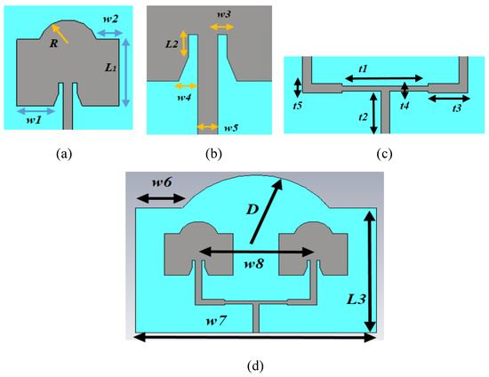
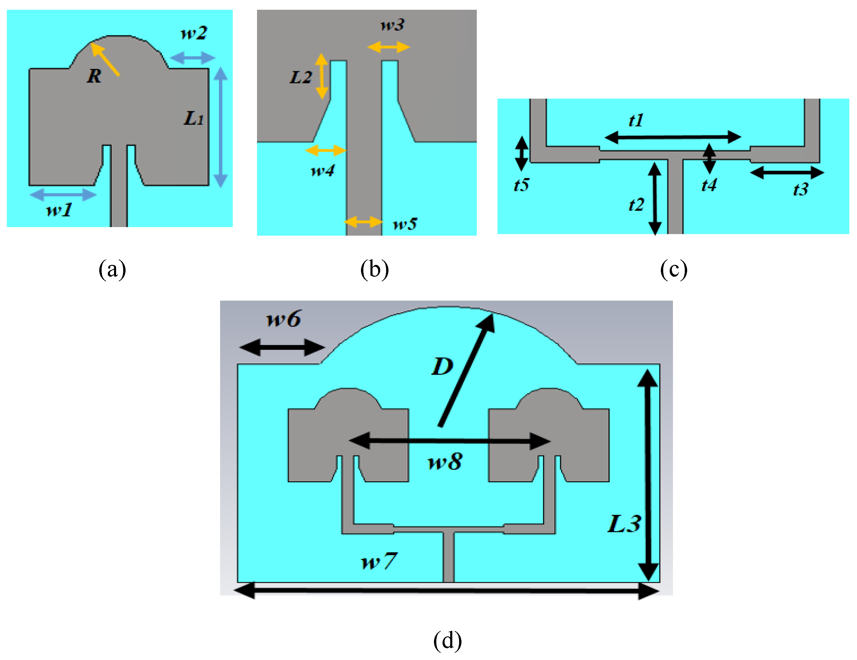
Figure 1 illustrates the different components of the proposed microstrip array antenna. Figure 1a presents the geometric structure of the single patch element of the array antenna. A semicircular structure is formed at the upper part of the patch and is defined by the radius R. The semicircular patch modification introduced through the radius R directly influences the surface current distribution on the upper radiating region of the patch. By altering the geometry of this region, the current flow is redistributed and the effective electrical path length is adjusted in a controlled manner. This also modifies the equivalent reactive loading of the radiator. As R decreases, the inductive loading is reduced, leading to a shorter effective electrical length and an upward shift in the resonance frequency. Hence, the R-based semicircular profile not only acts as a resonance-tuning parameter but also as a current-distribution control mechanism that improves frequency stability under conformal bending.
Figure 1.
(a) Geometrical structure of the single patch element, (b) transmission line of the single microstrip antenna element, (c) feeding network of the array configuration, and (d) integrated view of the proposed microstrip array antenna.
Figure 1b shows the transmission line structure of the single microstrip antenna element, while Figure 1c presents the feeding network of the array configuration. The feed network was designed using a microstrip transmission line structure to ensure proper matching with a SMA connector. In the design process, the substrate thickness, relative dielectric constant, and operating frequency were taken as , , and , respectively. Based on these electrical parameters, the width of the main input microstrip line providing approximately characteristic impedance was determined to be . To improve impedance matching and reduce reflections at the power division region, higher-impedance microstrip sections were introduced between the input line and each antenna element. Accordingly, the widths of the impedance transformer sections feeding the individual elements were selected to be approximately .
The physical lengths of the impedance transformer sections were determined according to the quarter-guided-wavelength principle on the microstrip line and were further optimized using full-wave electromagnetic simulations. As a result of this optimization process, the final length of these sections was set to . Moreover, the horizontal feed branches extending from the T-junction to the antenna elements were designed to provide equal electrical path lengths in order to achieve in-phase excitation of both elements, and each branch length was chosen as . In addition to the geometrical description, the key design parameters of the proposed conformal array were selected based on fundamental array behavior and electromagnetic constraints rather than purely numerical optimization. In particular, the center-to-center spacing between the two patch elements, defined by w8 = 80 mm, corresponds to approximately 0.64 × at an operating frequency of 2.4 GHz. This spacing lies within the well-established theoretical range for two-element broadside arrays, ensuring constructive interference in the broadside direction while remaining below the grating-lobe threshold. At the same time, selecting an inter-element distance above half a wavelength effectively mitigates excessive near-field mutual coupling, which is critical for maintaining stable impedance matching and consistent radiation characteristics under conformal deformation. Therefore, the chosen spacing represents a balanced compromise between array compactness, coupling suppression, and sidelobe control. Similarly, the semicircular patch modification and substrate-level curvature were jointly considered as part of an integrated electromagnetic design strategy aimed at preserving resonance stability and radiation performance under bending. This design approach ensures that the observed performance robustness originates from physically justified parameter selection rather than from isolated numerical tuning alone. All geometric and electrical dimensions were finalized through full-wave simulations to obtain optimum impedance matching, radiation performance, and array directivity.
The choice of a 2 × 1 array configuration was made as a practical trade-off between gain enhancement and conformal simplicity. In backscatter systems, the objective is to capture as much of the ambient signal as possible and reradiate it effectively toward the final receiver. For this reason, a more directional and higher-gain antenna structure is desirable in order to reduce signal loss and strengthen the backscatter link budget. A single patch element would provide a more compact geometry, but with lower gain and weaker directivity. In contrast, a larger array such as a 2 × 2 configuration could potentially provide further gain improvement, but at the expense of increased physical size, more complex feed-network design, and reduced suitability for controlled bending experiments. Therefore, the 2 × 1 structure was preferred as a balanced solution that improves signal capture and reradiation capability while preserving manageable fabrication, feeding simplicity, and conformal applicability.
Figure 1d depicts an integrated view of the proposed conformal array antenna. A semicircular curvature with a radius of D is applied to the upper part of the substrate material hosting the array antenna. This geometric curvature is introduced to enhance the mechanical conformability of the antenna structure. In particular, it enables the antenna to operate without significant performance degradation while preserving its structural integrity on cylindrical or curved mounting surfaces. As a result, the proposed antenna becomes suitable not only for planar surfaces but also for various curved platforms. Table 3 presents the optimized geometrical and feed network parameters of the proposed structure.
Table 3.
Optimized dimensions of the proposed structure.
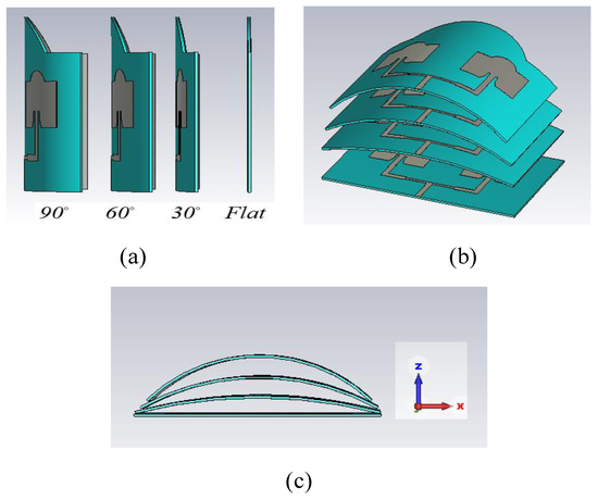
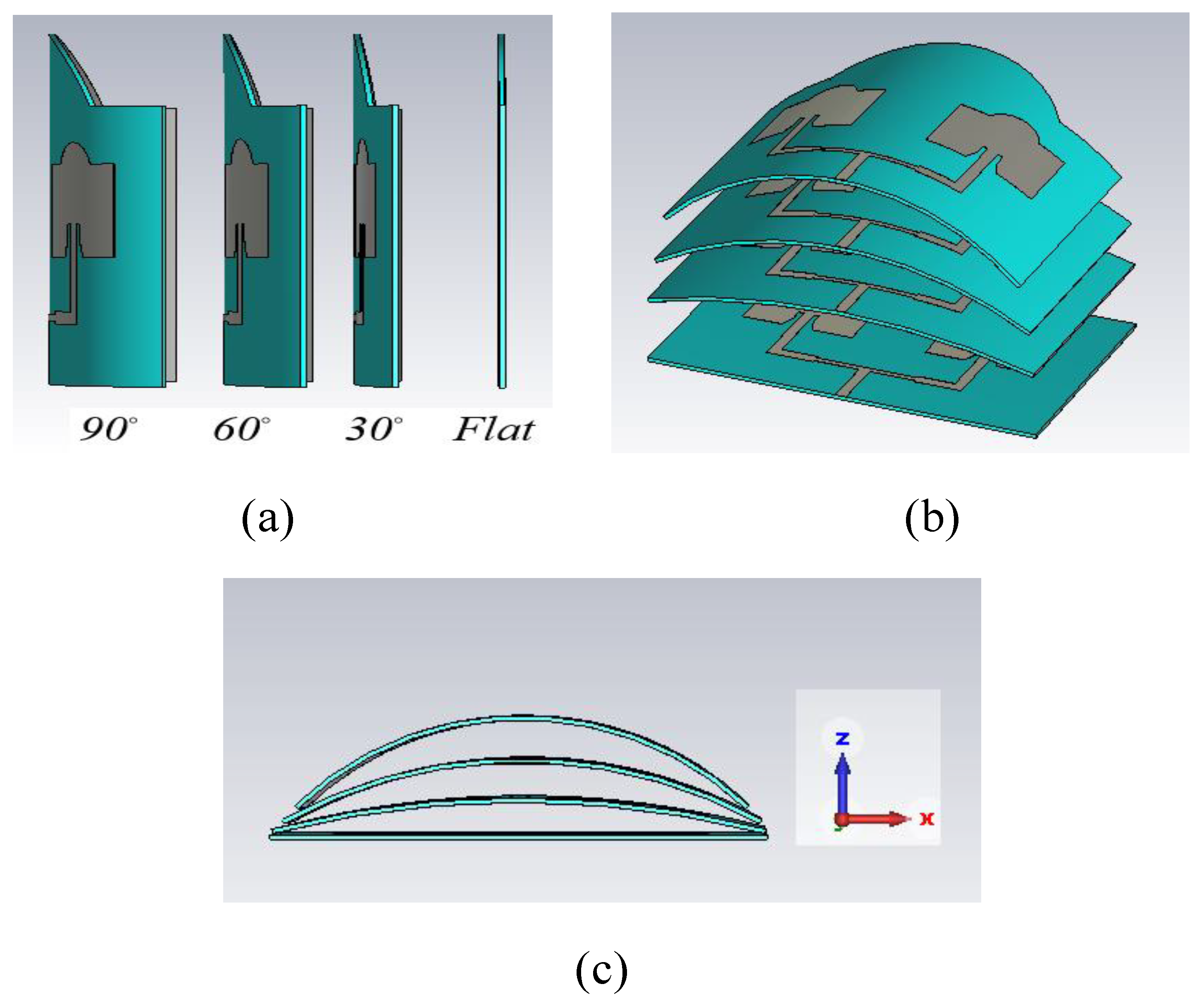
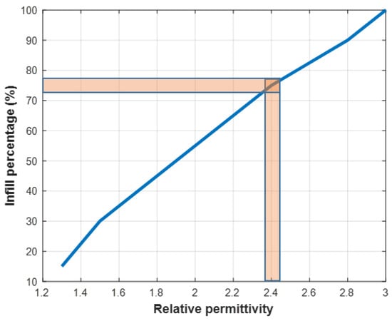
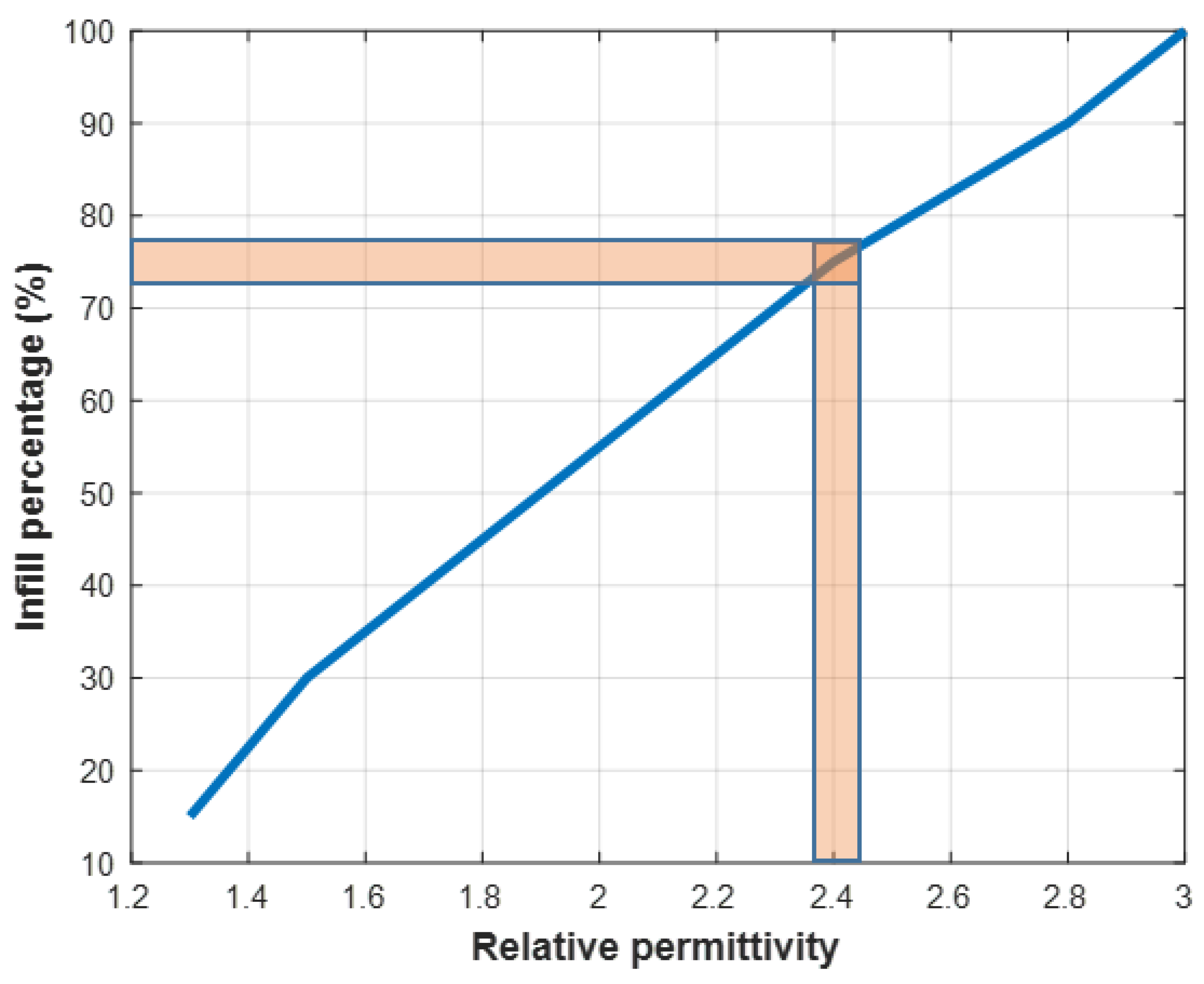
Figure 2 illustrates views of the proposed conformal microstrip array antenna under different bending conditions, namely flat, , , and . In all configurations, the substrate material is selected as PREPERM ABS300, which has a relative permittivity of and a dielectric loss tangent of [21]. These bending scenarios are introduced to systematically investigate the electromagnetic performance of the antenna under increasing curvature levels. Figure 3 presents the relationship between the infill percentage of the PREPERM ABS300 filament and the resulting effective relative permittivity. As clearly observed from Figure 3, an effective dielectric constant of is achieved when the infill percentage is adjusted to approximately . Therefore, in all antenna prototypes fabricated within this study, the infill ratio of the 3D-printed substrate is fixed at to accurately realize the targeted dielectric properties.
Figure 2.
(a) Side view of the proposed conformal array antenna under different bending angles (flat, , , and ), (b) perspective view, and (c) front view.
Figure 3.
Infill percentage of PREPERM ABS300 filament.
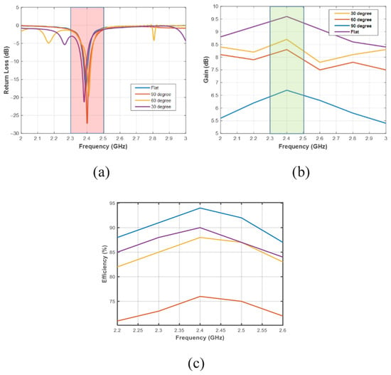
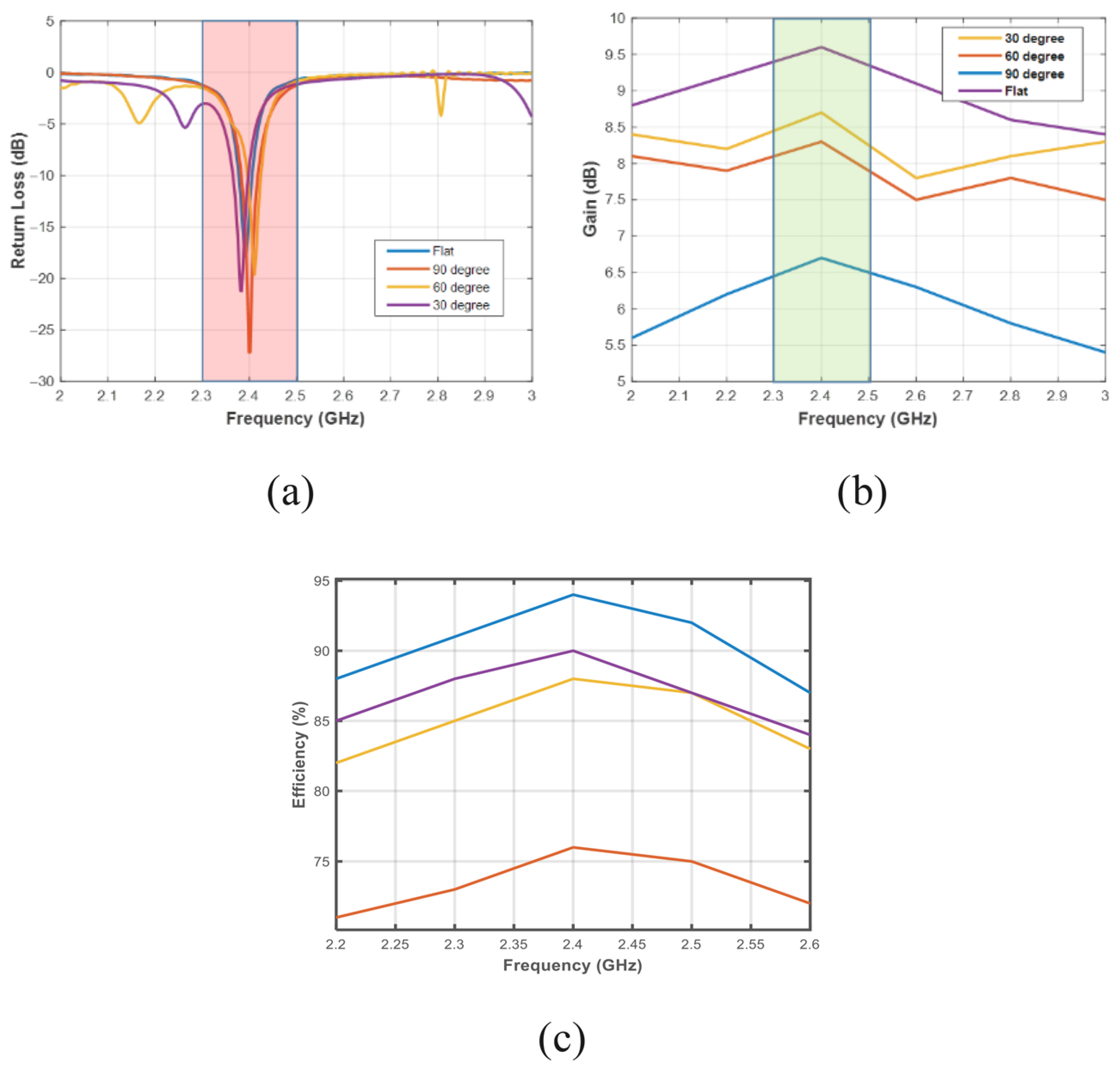
Figure 4a presents the simulated reflection coefficient (S11) results of the proposed conformal microstrip array antenna under flat, , , and bending conditions. It is clearly observed that, for all bending scenarios, the antenna operates below the dB threshold within the targeted 2.4 GHz ISM band. In the flat configuration, a deep resonance is observed around 2.4 GHz, while a slight frequency shift appears as the bending angle increases. However, thanks to the proposed resonance tuning mechanism based on the semicircular R parameter, these shifts are effectively compensated, and stable impedance matching is preserved across all conformal states.
Figure 4.
Performance of the proposed antenna under different bending conditions (a) reflection coefficient, (b) antenna gain, and (c) radiation efficiency.
Figure 4b shows the frequency-dependent variation of the antenna gain for the same bending scenarios. In the flat condition, the antenna exhibits a maximum gain of approximately 9.5–9.7 dBi, while a gradual reduction in gain is observed with increasing bending angle. The gain remains within the range of 8–8.7 dBi for the and bending cases, whereas it decreases to approximately 6.5–6.7 dBi under the bending condition. Nevertheless, the antenna maintains a sufficiently high and usable gain level in all conformal configurations. These results clearly demonstrate that the proposed array geometry can largely preserve its electromagnetic performance against conformal deformations.
Figure 4c illustrates the frequency-dependent variation in the radiation efficiency for different bending conditions. In the flat configuration, the maximum efficiency reaches approximately 94–95%, while it decreases to about 90% and 88% for the and bending cases, respectively. Under the most severe bending condition of , the radiation efficiency drops to approximately 75–76%. This degradation can be attributed to the effects of conformal deformation on conductor losses and surface current distribution. Nevertheless, achieving an efficiency higher than 70% even at a bending angle clearly indicates that the proposed antenna structure is a strong candidate for flexible and conformal platform applications.
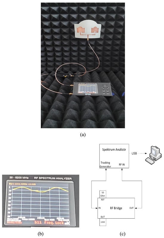
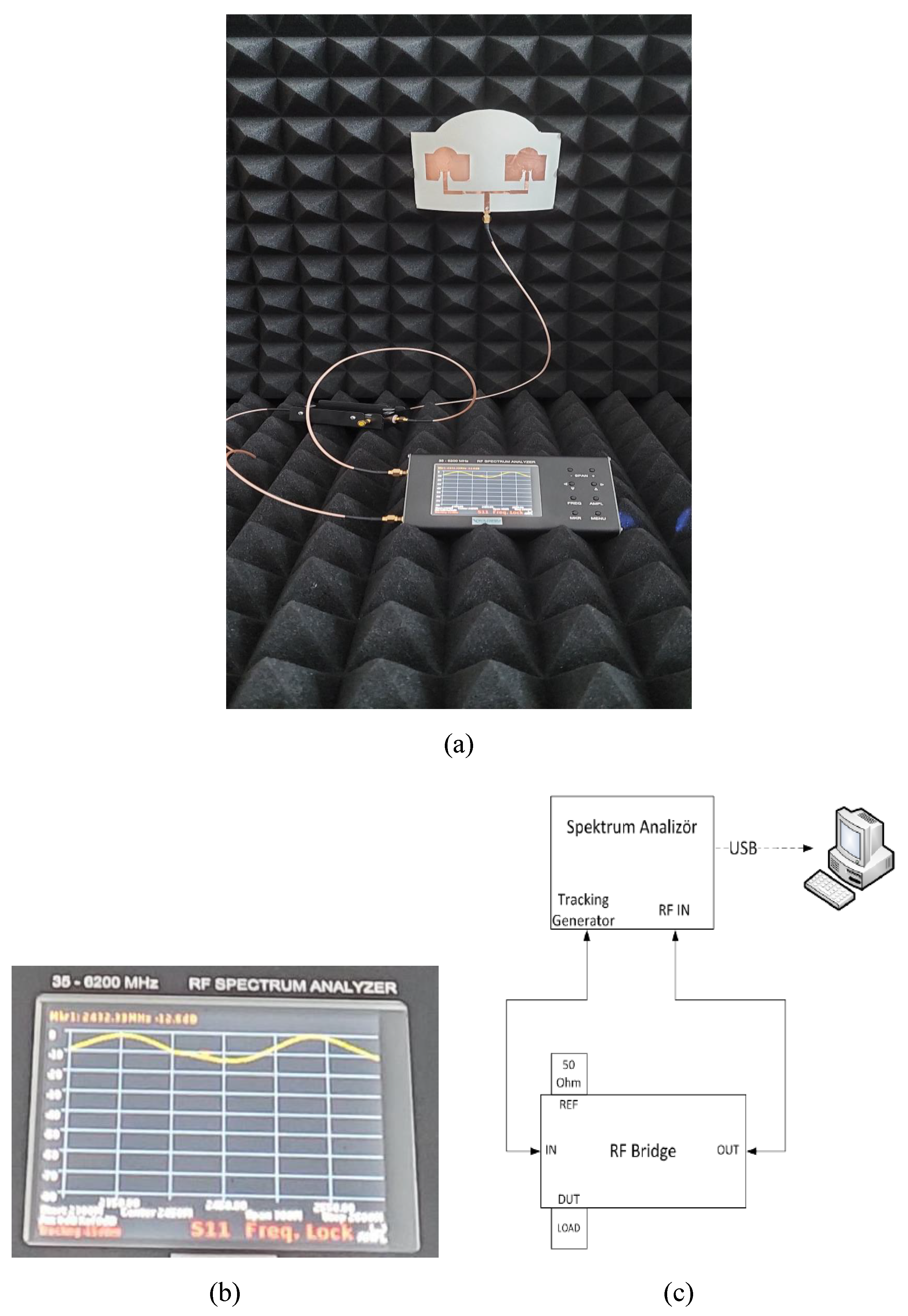
Figure 5 presents the experimental measurement setup and the measured results of the proposed conformal microstrip array antenna. Figure 5a illustrates the actual measurement setup inside the anechoic chamber, where the antenna is connected to the measurement instrument via a coaxial cable and surrounded by RF-absorbing foams to minimize environmental reflections. Figure 5b shows a snapshot of the measured S11 response displayed on the spectrum analyzer screen. Figure 5c shows the block diagram of the RF bridge-based spectrum analyzer measurement system used for the S11 measurements. In this configuration, the tracking generator output of the spectrum analyzer is applied to the antenna through the RF bridge, and the reflected signal is received at the RF input of the analyzer to obtain the reflection coefficient.
Figure 5.
Return-loss measurement of the proposed conformal array antenna: (a) Measurement setup, (b) measured response, and (c) RF bridge-based setup.
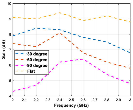
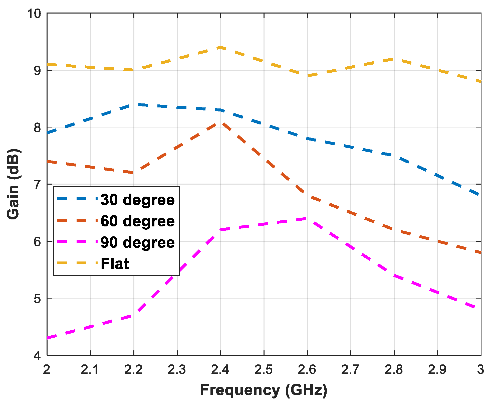
Figure 6 presents the measured gain variation versus frequency for the antenna under flat, , , and bending conditions. According to the measurement results, the antenna achieves a maximum gain of approximately 9–9.4 dBi around 2.4 GHz in the flat configuration. For the bending condition, the measured gain remains in the range of approximately 8–8.4 dBi, while it decreases to about 7–8 dBi under the bending condition. At the highest bending angle of , the antenna gain is reduced to approximately 6–6.5 dBi. Nevertheless, for all bending configurations, the antenna maintains stable and usable gain levels within the 2.4 GHz operating band.
Figure 6.
Measured gain of the proposed conformal array antenna for flat, , , and bending conditions.
To evaluate the repeatability of the measured gain values, five independent repeated measurements were carried out at 2.4 GHz for each bending state, and the resulting statistical metrics are summarized in Table 4. The obtained standard deviation values are 0.19 dB, 0.27 dB, 0.34 dB, and 0.22 dB for the flat, 30°, 60°, and 90° cases, respectively, while the corresponding coefficient of variation values remain within 2.03–4.14%. In addition, the 95% confidence intervals remain relatively narrow for all bending states. These results indicate that the measurement spread is limited and that the observed gain reduction with increasing bending angle represents a consistent and repeatable experimental trend.
Table 4.
Statistical variability analysis of measured antenna gain at 2.4 GHz under different bending states.
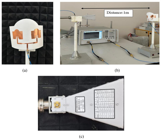
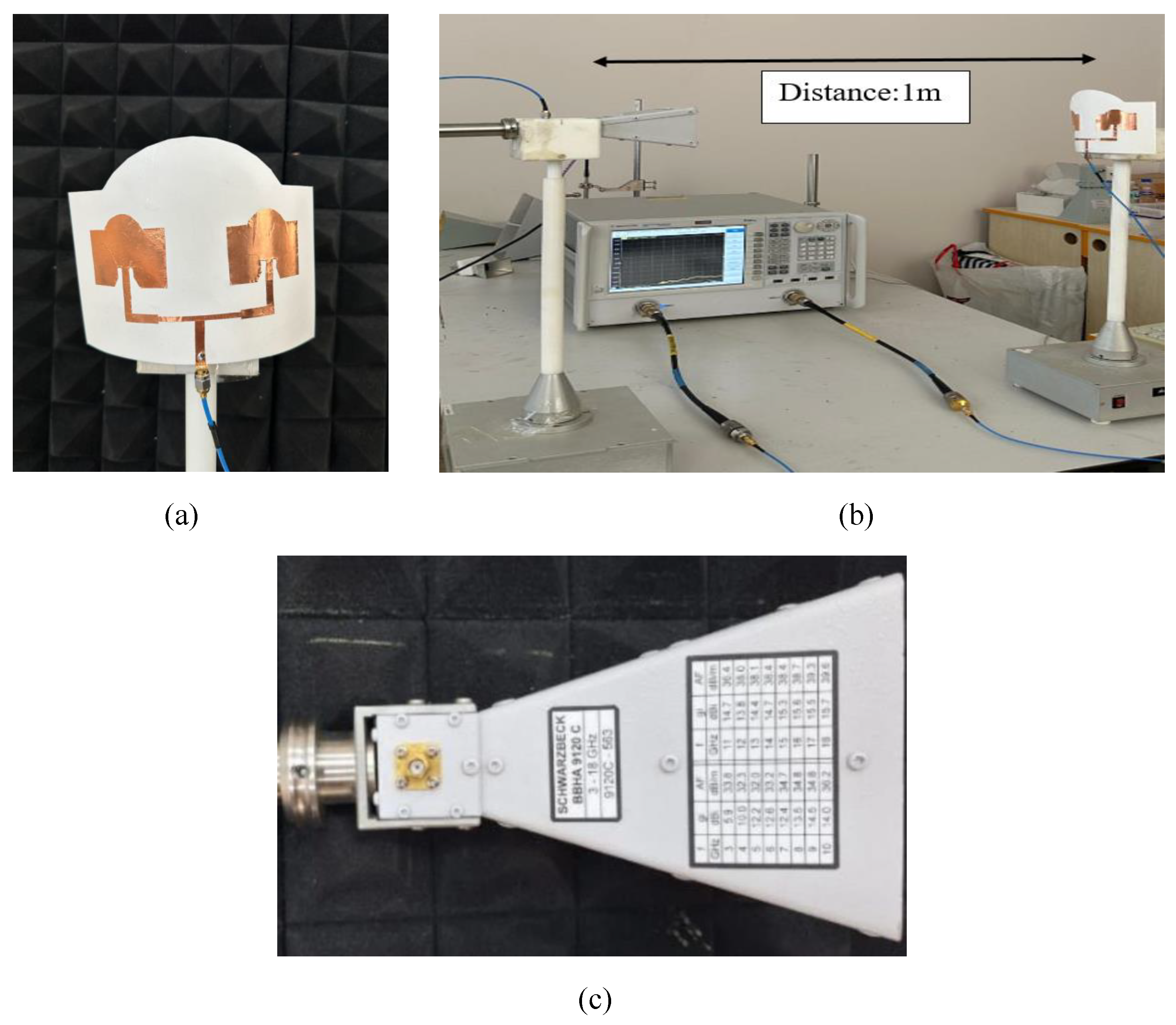
The antenna characterization associated with the gain measurements was carried out in a quasi-anechoic chamber-like environment supported by RF absorbing materials. In this arrangement, a wideband horn antenna with known characteristics, operating over the 3–18 GHz range, was used as the reference antenna and connected to an Agilent Technologies PNA-L vector network analyzer (N5134A). The proposed conformal antenna was placed opposite to this reference horn antenna, and comparative gain-related measurements were performed under the same controlled setup for the different bending conditions.
The gain characterization was performed using a comparative free-space substitution method referenced to a calibrated standard gain horn antenna. In this setup, the reference horn antenna and the antenna under test (AUT) were positioned face-to-face along the same boresight axis with a fixed separation of 1 m, while the antenna heights and polarization conditions were kept the same throughout the measurements. The AUT gain was then extracted from the received-power difference relative to the reference antenna under the same measurement geometry. Since the same cables, instrument settings, antenna separation, and alignment conditions were preserved during both the reference and AUT measurements, the common measurement-chain effects were largely canceled in the differential gain calculation. In addition, the selected 1 m separation satisfies the far-field condition for both antennas according to the Fraunhofer criterion. A photograph of the gain-measurement configuration is provided in Figure 7.
Figure 7.
Photographs of the gain-measurement (a) the AUT, (b) the overall face-to-face measurement geometry with a fixed antenna, (c) the reference standard gain horn antenna (Schwarzbeck BBHA 9120).
It should also be noted that the uncertainty treatment adopted in this work is limited to a practical comparative measurement framework and does not constitute a complete metrology-grade uncertainty-budget analysis referenced to a national standard. The main remaining uncertainty sources include alignment tolerances, connector repeatability, small cable-position variations, residual environmental reflections, minor polarization mismatch, and instrument reading fluctuations. Although these effects were minimized as much as possible by preserving the measurement geometry and maintaining the same measurement chain, they were not completely eliminated, and no formal expanded uncertainty budget was calculated. This clarification is intended to define the scope of the gain evaluation more accurately and to avoid overstating the metrological precision of the reported results.
The conformal antenna has never been experimentally evaluated under four fixed geometrical states: flat, 30°, 60°, and 90°. These bending cases were intentionally selected to represent progressively increasing curvature in a controlled and comparable manner. In all cases, the same antenna topology, feed structure, metallization approach, and fabrication procedure were preserved, while only the bending angle was changed. In addition, all prototypes were manufactured using PREPERM ABS300 with a fixed infill ratio of 75% in order to maintain dielectric consistency across the tested conformal configurations.
For the experimental characterization, an ARINST SSA TG R2 spectrum analyzer was used for both return-loss and received-power measurements. In the reflection-coefficient measurements, the tracking-generator output of the spectrum analyzer was connected to the antenna under testing through an RF bridge, and the reflected signal was monitored through the RF input of the same instrument. All return-loss measurements were performed using the same practical connection arrangement, cable setup, and feeding condition for each conformal state in order to ensure consistency among the measured cases.
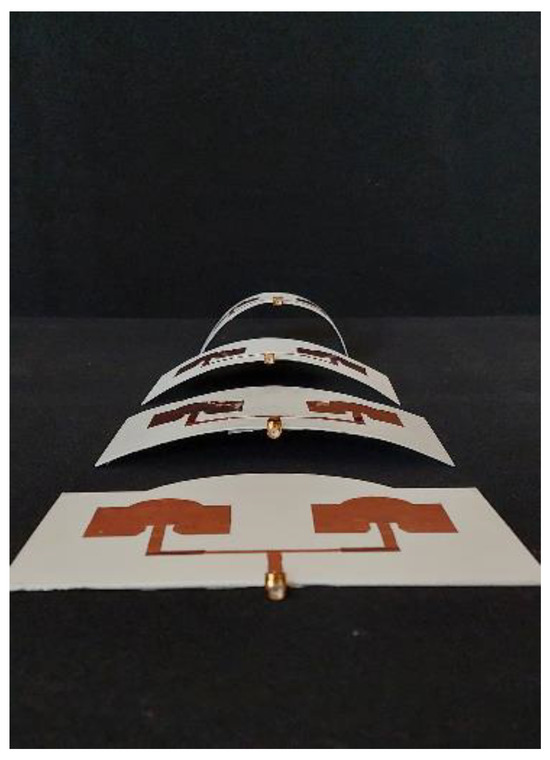
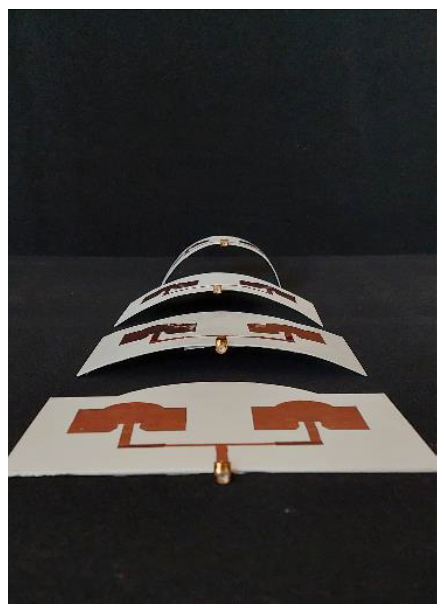
Figure 8 shows the photographs of the fabricated conformal microstrip array antenna under different bending configurations. The prototypes were manufactured using PREPERM ABS300 material with a 75% infill ratio to accurately achieve the targeted dielectric constant of 2.4. As seen in the figure, the antenna maintains its structural integrity across flat, moderately curved, and highly curved conditions, demonstrating its excellent mechanical flexibility. The copper patch layer adheres uniformly to the 3D-printed substrate, and the SMA connector is positioned to ensure reliable feeding during measurements. These photographs confirm that the proposed design can be successfully fabricated and physically bent without causing delamination, cracking, or distortion in the radiating elements, validating its suitability for conformal and surface-mounted wireless applications.
Figure 8.
Photograph of the manufactured conformal antennas.
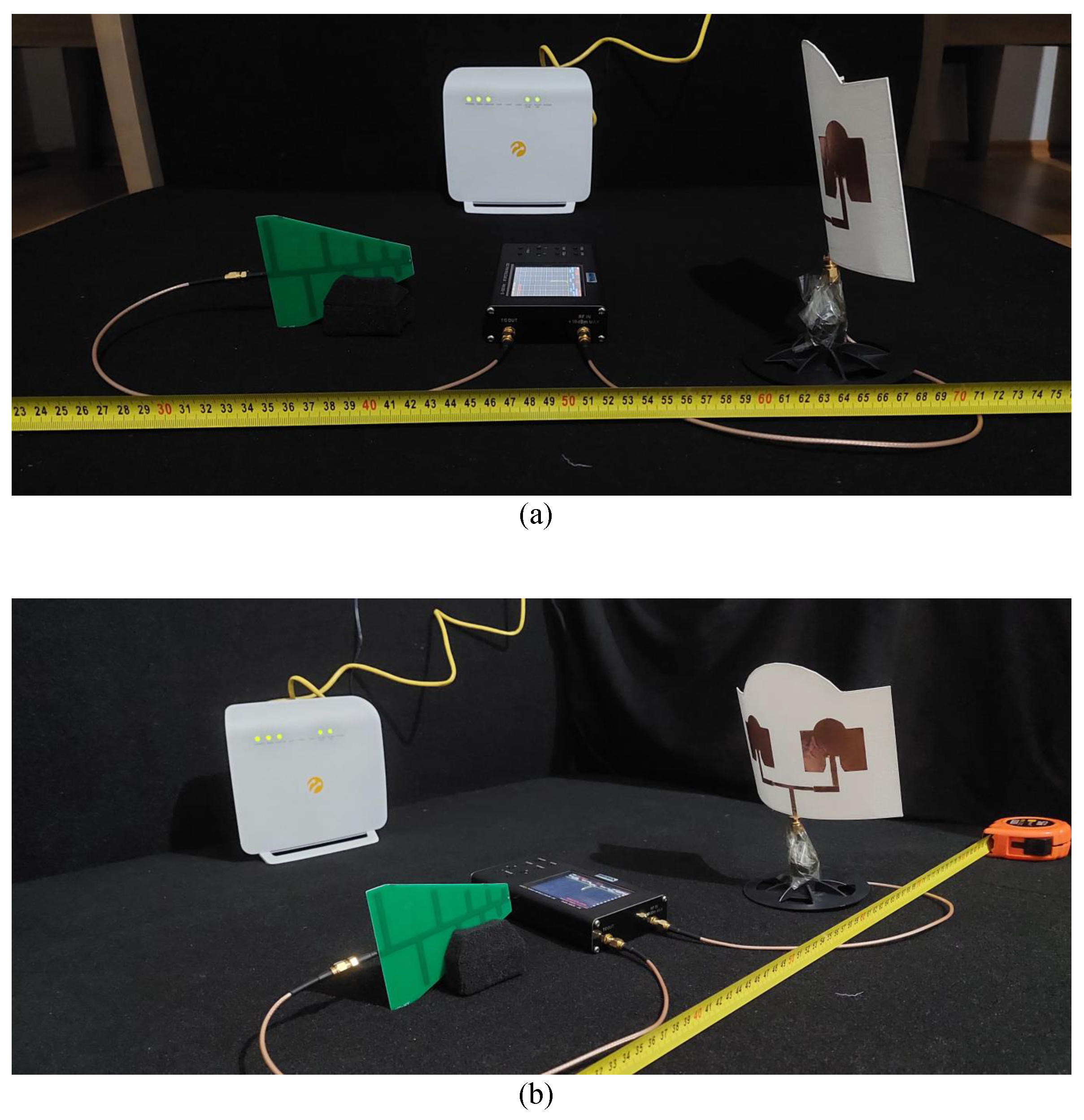
Figure 9 illustrates the indoor measurement setup used to evaluate the backscatter communication performance of the proposed conformal microstrip array antenna. A commercial 2.4 GHz WiFi router was employed as the ambient RF illumination source, positioned at a height representative of typical home-office deployments. The incident WiFi signal is received by the proposed array antenna, which operates as a passive backscatter transmitter (tag) and reflects the modulated signal toward the receiver.
Figure 9.
Experimental set-up (a) front view (b) perspective view.
The backscattered signal is then captured by the LPDA (Log-Periodic Dipole Array) antenna, which serves as the final receiving node in the system. The separation distances between the WiFi source, the backscatter antenna, and the LPDA receiver were carefully adjusted to emulate realistic short-range IoT communication scenarios. All measurements were performed in an indoor environment to minimize external interference and uncontrolled multipath reflections. This setup enables a reliable assessment of the backscatter performance of the proposed conformal antenna under practical deployment conditions. During the indoor backscatter experiments, the WiFi router and the LPDA receiving antenna were kept at fixed positions for each measurement sequence, and only the bending state of the conformal backscatter antenna was changed sequentially. The separation between the backscatter antenna and the LPDA receiver was kept constant at 60 cm throughout the measurements, while the WiFi source was positioned at predefined distances according to the selected test case. This controlled procedure was adopted to improve repeatability and to ensure that the observed variations in received power and bit-rate performance mainly originated from the conformal geometry difference rather than from changes in node placement or measurement arrangement.
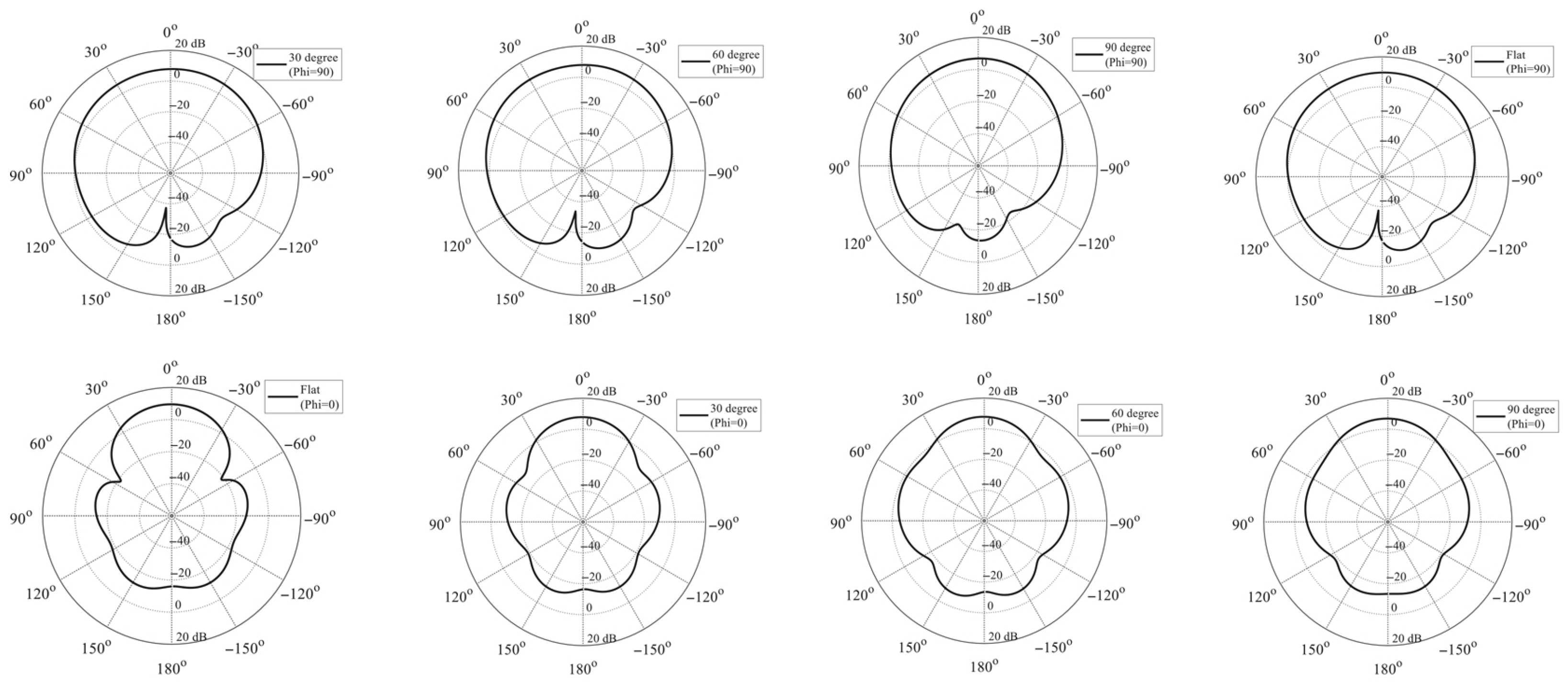
Figure 10 presents the simulated 2D polar radiation patterns in the (H-plane) and (E-plane) for the conformal backscatter antennas under flat, , , and bending configurations at an operating frequency of 2.4 GHz. In the flat configuration, the main radiation lobe in both planes is clearly concentrated around , exhibiting a pronounced broadside radiation characteristic with dominant forward radiation. This confirms that the unbent antenna provides high directivity and efficient forward radiation performance. For the and bending cases, the main-lobe direction is generally preserved in both the E- and H-planes; however, a progressive broadening of the main lobe, degradation of radiation symmetry, and a gradual reduction in peak radiation levels are observed. These effects indicate that increasing curvature leads to a redistribution of surface currents and a reduction of the effective radiating aperture. In particular, the bending case exhibits a more noticeable loss of directivity in both planes. In the bent configuration, the radiation patterns in both planes experience severe distortion, characterized by a significantly widened main lobe and pronounced increases in radiation toward the lateral and backward directions. This behavior demonstrates that excessive conformal deformation strongly degrades the effective aperture and directional performance of the antenna.
Figure 10.
2D polar radiation patterns of the conformal backscatter antennas at 2.4 GHz for different bending configurations at (H-plane) and (E-plane).
3. Communication Setting for Conformal Array-Assisted WiFi Backscatter
We consider a symbiotic radio link composed of a WiFi transmitter (node t), a conformal backscatter array (), and an LPDA receiver (). The system model considered follows the TDMA-based symbiotic/backscatter protocol reported in [20]. The elements required to map the measured antenna-dependent power products to the link-level rate expressions used in the performance evaluation are summarized below.
3.1. Link Representation and Angle-Dependent Gain of the Conformal Array
Let and denote the (fixed) gains of the WiFi transmitter and the LPDA receiver, respectively. The conformal array gain is angle-dependent and is denoted by , where is the bending angle. A free-space reference model is used only as a normalization baseline; in the numerical results, the terms involving are replaced by the corresponding experimentally obtained power products. Under the free-space reference, the channel gains are written as
where is the wavelength and , , and are the link distances. The receiver noise power at is .
3.2. Protocol Mapping and Notation
We adopt the normalized two-phase TDMA frame in [20]. For notational convenience, the two phase durations are denoted in this paper by and (a relabeling of the corresponding time variables used in [20]), satisfying
Phase 1 corresponds to the symbiotic relationship between the WiFi device and the antenna, while Phase 2 corresponds solely to the backscattering process.
3.3. Symbiotic Operation of WiFi Device and Conformal Array (Scenario-S1)
In our implementation, the effective backscatter power is characterized by the backscatter reflection coefficient and the signal power generated by the spectrum analyzer . Accordingly, the effective backscatter power used in Phase 1 (duration ), where the WiFi carrier is present, and the effective backscatter power used in Phase 2 (duration ), where backscatter-only operation is considered, are modeled as
where is the WiFi-transmitted power. By using expressions (1)–(3) with the protocol in [20], the system’s rate expressions can be written in the form summarized in Section 3.6.
3.4. Concurrent Transmission of WiFi Device and Conformal Array Antenna with Residual Interference (Scenario-S2)
To account for non-ideal decoding, we adopt the residual-SIC abstraction in [20]. In this paper, the residual-SIC factor is denoted by , which represents the fraction of the backscattered component that remains during direct-link decoding. Accordingly, the disturbance term for the direct-link decoding is elevated to , while the effect on the backscatter decoding is neglected due to its comparatively low received power. In this paper, the total bit transmission rate in Scenario-S2 is denoted by .
3.5. Evaluation Under LoS and NLoS Propagation
We consider two practical indoor conditions: LoS (unobstructed) and NLoS (obstructed/multipath). In both cases, we preserve the same protocol mapping and time-allocation constraints, while replacing the analytical power products (e.g., and ) with the corresponding values obtained from the measurements for each bending angle . This clearly demonstrates the effect of conformal array characteristics on end-to-end symbiotic/backscatter performance without the need to redefine the existing protocol.
3.6. Rate Formulation Used in This Work
We summarize here the rate expressions used in the present work under our own notation. These expressions follow the same TDMA-based WiFi backscatter framework adopted from [20], but are written here directly in the notation of this manuscript.
In Scenario-S1, during the first phase of duration , the WiFi transmitter and the conformal backscatter array jointly contribute to the reception at . The direct-link rate is written as
while the backscatter-link contribution in the same phase is
During the second phase of duration , only the backscatter transmission is considered, yielding
Hence, the total bit transmission rate in Scenario-S1 is evaluated as
where the QoS thresholds are adopted from [20].
In Scenario-S2, imperfect SIC is taken into account through the residual-interference factor x. Accordingly, the total rate is written as
In the analytical–experimental evaluation, the terms , , and are not treated only as abstractly linked budget quantities. Instead, for each bending angle and distance configuration, they are replaced by the corresponding experimentally obtained power values reported in Table 5 and Table 6 after conversion from dBm to linear scale. In this way, the previously established TDMA-based model is implemented directly with the measured antenna-dependent received powers.
Table 5.
Measured powers (dBm) under No Obstruction (LoS) for different bending angles and distance triplets in meters.
Table 6.
Measured powers (dBm) under Obstacle (NLoS) for different bending angles and distance triplets in meters.
4. Analytical–Experimental Bit-Rate Assessment Under LoS/NLoS Conditions
This section presents the experimental results and analytical evaluation of the backscatter communication system employing conformal backscatter antennas and a LPDA receiving antenna. All measurements were conducted in a residential (home) environment. A commercial WiFi router with an antenna gain of 2 dBi was used as the signal source, while the backscattered signal was received by an LPDA antenna with a gain of 5 dBi. The measurements were performed using a spectrum analyzer equipped with a tracking generator. The directional radiation characteristic of the LPDA antenna enabled high-sensitivity signal reception.
The backscatter antennas consist of four conformal configurations with different bending angles, and their measured gain values at 2.4 GHz are 9.4 dBi for the flat configuration, 8.3 dBi for the bent antenna, 8.1 dBi for the bent antenna, and 6.2 dBi for the bent antenna. These results clearly demonstrate that, at a 2.4 GHz operating frequency, the antenna gain degrades noticeably as the curvature increases. During the measurements, the flat backscatter antenna was first placed at the backscatter position, followed sequentially by the , , and bent antennas, while the WiFi source and the LPDA receiving antenna were kept fixed throughout all measurements.
Throughout all measurements, the separation between the backscatter antenna and the LPDA receiving antenna was kept constant at 60 cm. The WiFi source was positioned at equal distances from both the LPDA and the conformal backscatter antennas to ensure symmetric illumination conditions. In the first measurement case, this distance was set to 60 cm. Subsequently, the same measurements were repeated for increased WiFi-to-antenna distances of , , and , enabling a detailed investigation of distance-dependent backscatter performance.
To assess the robustness of the system under obstructed propagation conditions, the same set of distance-dependent measurements was repeated by placing a wall obstacle between the WiFi source and the antennas. This arrangement enabled a direct performance comparison between LoS and NLoS propagation environments for conformal backscatter communication. The experimentally obtained power measurement values are given in Table 5 and Table 6.
In the bit transmission rate simulations, the phase durations were selected by applying the time-allocation procedure in [20] under the parameter mapping summarized in Section 3 for the two considered scenarios (i.e., the symbiotic operation and the residual-interference case). To ensure QoS, we imposed minimum rate requirements denoted by , , and for Phase 1, Phase 2, and the residual-interference case, respectively. The system and measurement parameters used throughout the simulations were selected to be consistent with the values implemented in our MATLAB Online (R2025b) code. Specifically, we set , , W, W, , , and m. The QoS thresholds were chosen as bps/Hz, bps/Hz, and bps/Hz. For each distance configuration defined by the triplet , the scenario-based bit transmission rates were evaluated using both analytical (Friis-based) and experimental power terms, and the resulting trends were systematically compared between the No Obstruction (LoS) and Obstacle (NLoS) conditions.
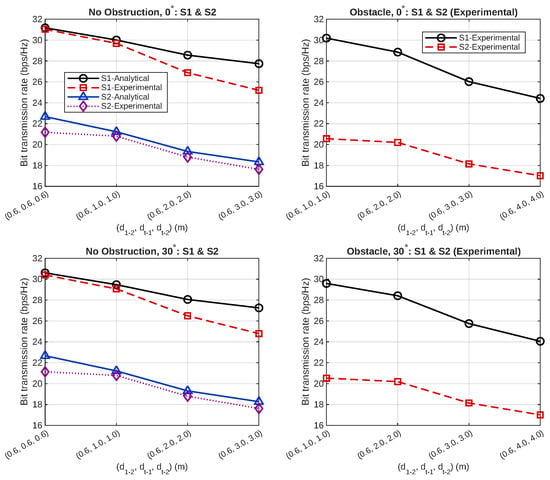
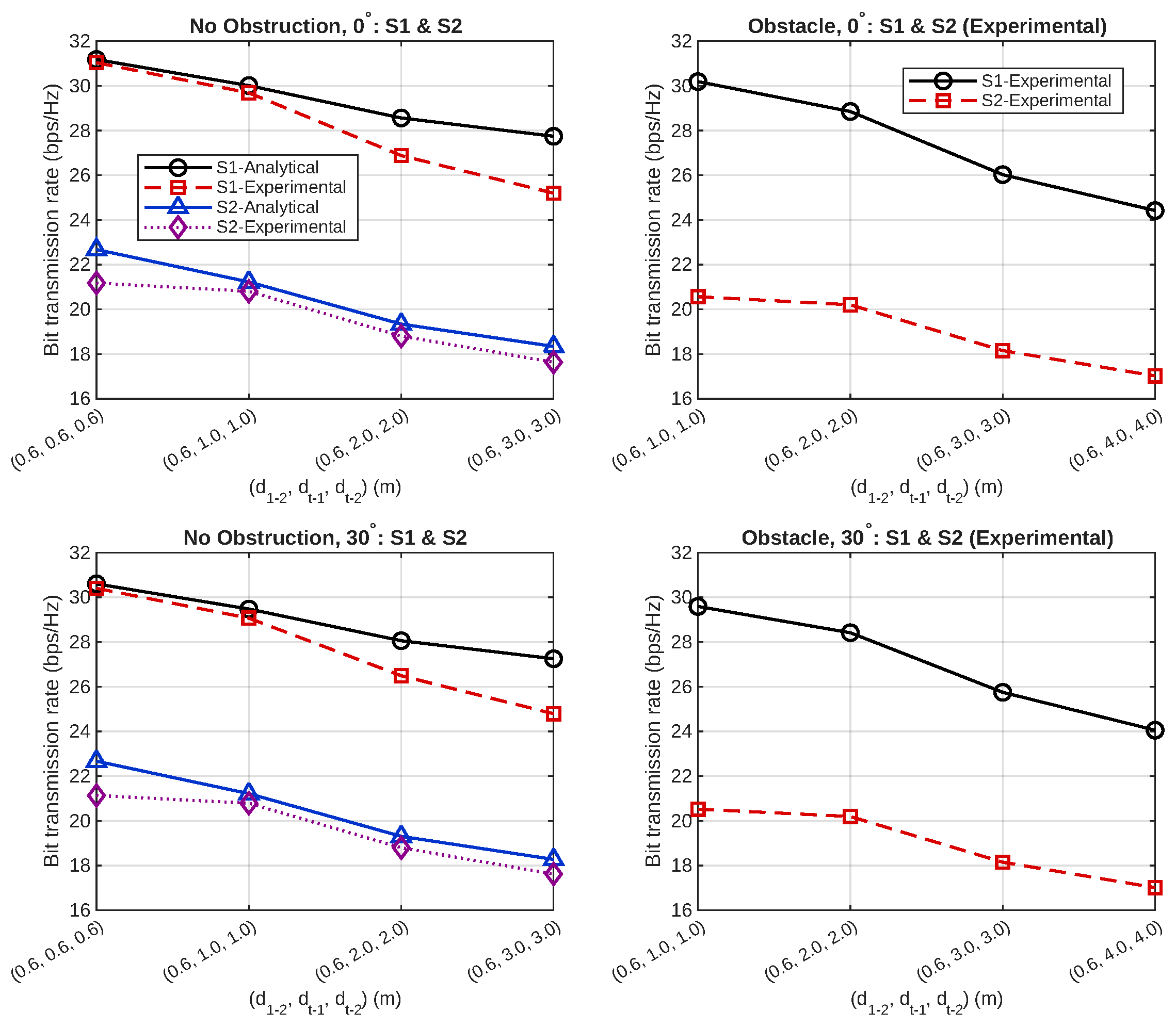
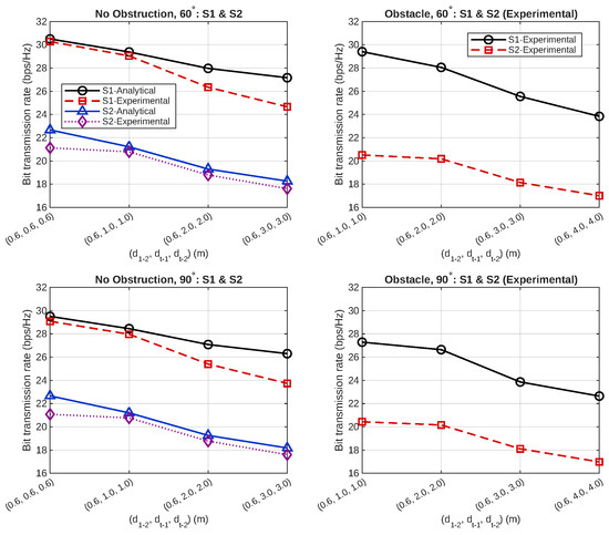
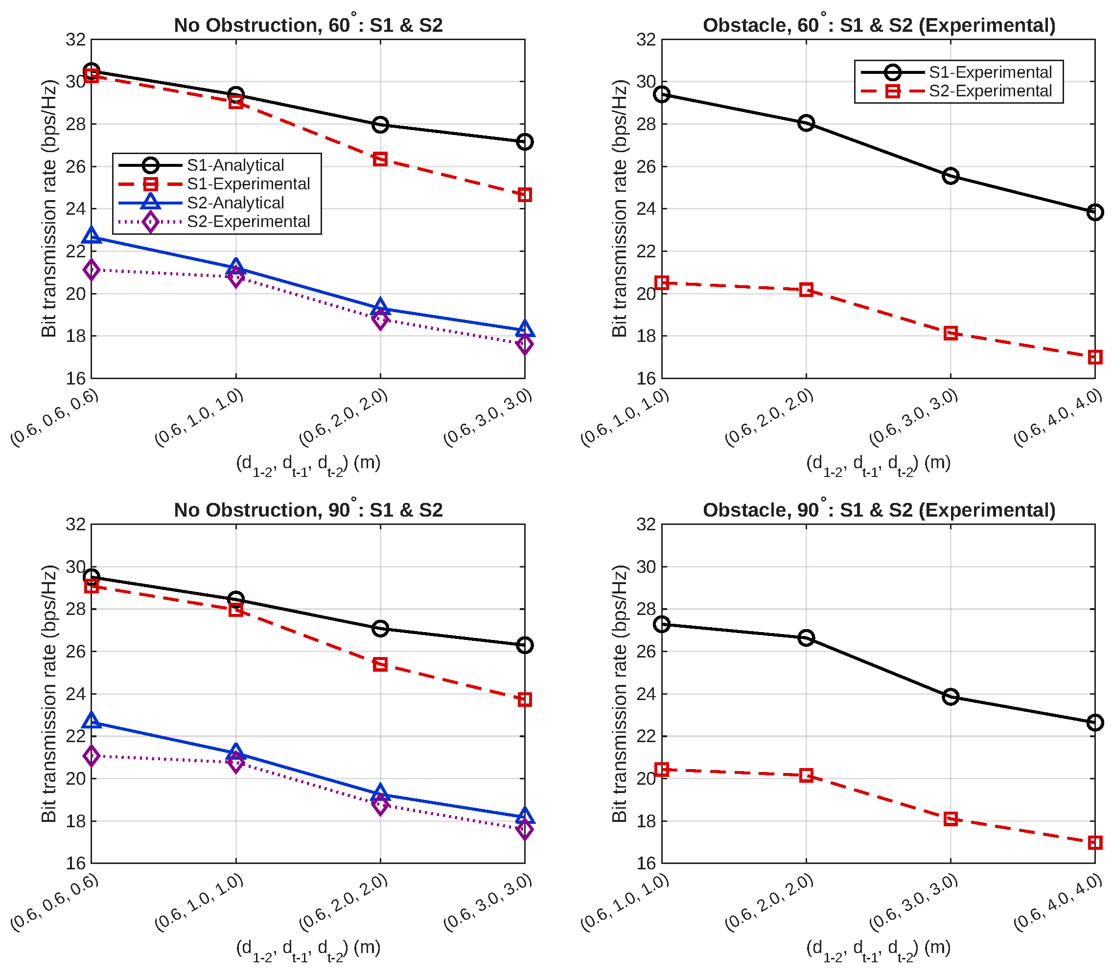
Figure 11 and Figure 12 show the variation of maximum bit transmission rates as a function of distance triplets for S1 and S2 scenarios under different bending angles (0°, 30°, 60°, 90°) and under both LoS (No Obstruction) and NLoS (Obstacle) conditions. In both figures, as the values of increase, the channel gain decreases, causing all curves to decrease monotonically; furthermore, under the same distance conditions, the rates measured in the Obstacle case remain at lower levels compared to No Obstruction, confirming the attenuation/shadowing effect caused by the obstacle. In the comparison between scenarios, it is observed that the S1 curves are higher than S2 at all angles and all triplets. This result is consistent with the residual interference modeled with x in S2, which reduces the effective SINR on the A2 side. The fact that the analytical and experimental curves follow the same decreasing trend in the No Obstruction column indicates that the proposed analytical channel model and experimental measurements are in general agreement. Any remaining deviations between the curves may be attributed to practical measurement-related factors such as minor alignment differences, cable and connector effects, and residual environmental reflections in the indoor measurement setup. Finally, the fact that the results in Figure 11 (0°–30°) are generally higher than those in Figure 12 (60°–90°), with the lowest ratios obtained at 90°, reveals that the link budget weakens and performance systematically decreases due to the degradation of the effective gain/radiation characteristic of the conformal array as the bending angle increases. In Scenario-S2, the measured power products affected by the bending angle appear in both the desired backscatter component and the residual-interference term associated with imperfect SIC (see [20]). Therefore, when bending reduces the effective backscatter level, it simultaneously reduces the residual interference seen by the direct-link decoding, yielding a largely compensatory behavior. As a result, the S2 rate trends remain nearly unchanged with respect to the bending angle, and the small remaining deviations can be further mitigated by the frame-level time allocation over under the imposed QoS thresholds.
Figure 11.
Bit transmission rate comparison of Scenario 1 (S1) and Scenario 2 (S2) for bending angles and .
Figure 12.
Bit transmission rate comparison of Scenario 1 (S1) and Scenario 2 (S2) for bending angles and .
From an antenna-design perspective, these results also clarify the distinction between the present study and our earlier planar backscatter work. Unlike our previous single planar microstrip configuration, the proposed antenna here adopts a 2 × 1 conformal array structure and is experimentally evaluated under multiple discrete bending states. This makes it possible to examine not only the directional array behavior of the antenna, but also how conformal deformation progressively influences gain, radiation characteristics, and the resulting backscatter-link performance under practical indoor conditions.
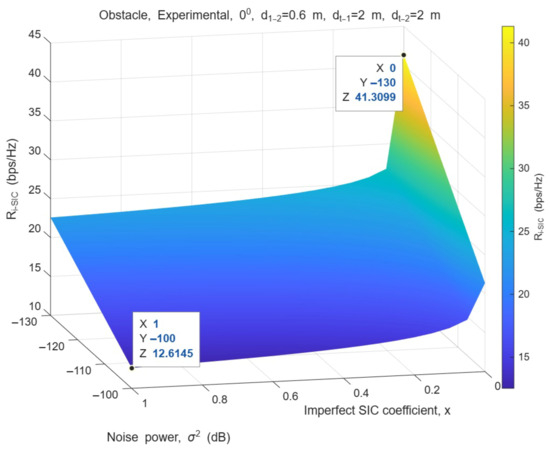
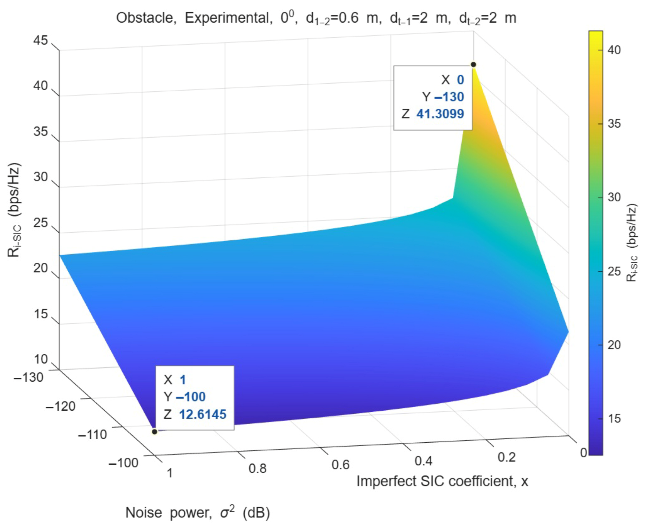
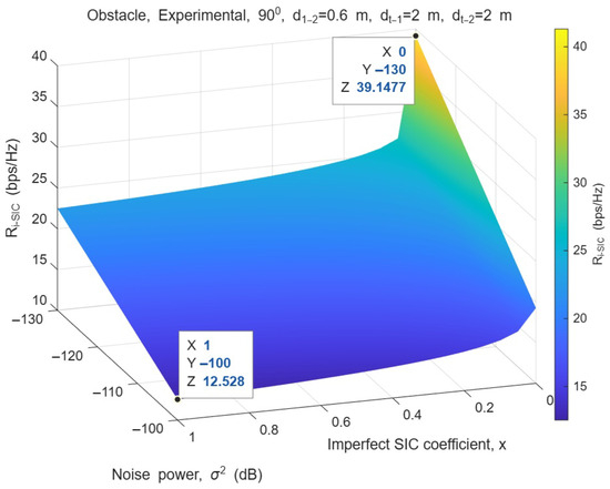
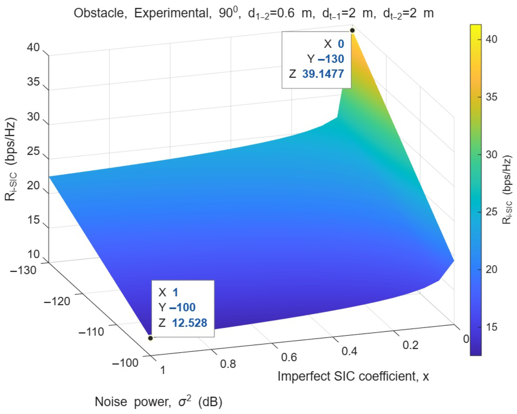
Figure 13 and Figure 14 show how the value in the S2 scenario changes with noise power (dB) and imperfect SIC coefficient x under bending angles of and , respectively, in an obstacle environment and for a fixed distance triplet . In both figures, as decreases (lower noise level), increases significantly; similarly, as x decreases (better SIC, less residual interference), the ratio rises sharply. This trend corresponds to the decrease in the denominator and the increase in the capacity term as x decreases in the expression included in the SNR term. When the figures are considered together, the fact that the surface is generally shifted slightly downwards at compared to shows that bending weakens the effective gain/connection budget, limiting the maximum level achievable under the same conditions; however, the fact that the surface shape is largely preserved confirms that the dominant factors determining performance in this graph are the and x parameters, and that the angle effect manifests itself more as a “level shift”.
Figure 13.
versus noise power and imperfect SIC coefficient x under obstacle conditions for bending.
Figure 14.
versus noise power and imperfect SIC coefficient x under obstacle conditions for bending.
Table 7 (LoS/No Obstruction) and Table 8 (NLoS/Obstacle) show the effect of QoS thresholds on the achievable bit transmission rate and feasibility in scenarios S1 and S2 under a fixed distance triplet . For S1, it is observed that as increases, the achieved rates decrease, and above a certain threshold, the optimization problem loses its feasibility as Inf. In the LoS condition, S1-Exp values are approximately – bps/Hz for and approximately – bps/Hz for , and no feasible solution is found at higher thresholds. In the NLoS condition, a similar trend is maintained, but the earlier loss of feasibility, especially for , indicates that increasing the bending angle weakens the connection budget, making it more difficult to meet the QoS constraints. On the S2 side, the fact that the values given in the tables remain almost constant despite different pairs stems from the fact that the determining constraint in S2 optimization is essentially ; indeed, while S2-Exp remains in the range of approximately – bps/Hz for and 18 in LoS (S2-An approximately – bps/Hz), at thresholds of and above, the results become Inf. and feasibility is lost. Similarly, in NLoS, for and 18, S2-Exp remains constant in the range of approximately – bps/Hz, while for , Inf. is obtained in all rows. These findings reveal that in the S2 scenario, the maximum level that the system can reach constitutes an upper limit, and when exceeds this limit, optimization fails to produce a feasible solution.
Table 7.
Achievable bit transmission rates (bps/Hz) versus QoS thresholds for the No Obstruction (LoS) condition with the fixed distance triplet . Inf. denotes an infeasible optimization problem (no feasible solution) under the given QoS constraints.
Table 8.
Achievable bit transmission rates (bps/Hz) versus QoS thresholds for the Obstacle (NLoS) condition with the fixed distance triplet . Only experimental results are reported.
5. Conclusions and Future Work
This study presents a 2 × 1 microstrip array antenna approach, entirely 3D-printed using PREPERM ABS300, for symbiotic backscatter connections utilizing ambient WiFi signals in the 2.4 GHz ISM band. Starting from a planar configuration, 30°, 60°, and 90° conformal configurations are systematically designed and evaluated through simulation and measurement validation. This provides a comprehensive experimental demonstration of the applicability of PREPERM ABS300 material in conformal antenna applications. Furthermore, the study goes beyond electromagnetic metrics, analyzing the effect of bending angle-dependent gain variation on end-to-end bit rate performance within a TDMA-based framework at the protocol level. The findings reveal that bit transmission rate decreases as the bending angle increases, and feasibility is lost earlier, particularly at tight QoS thresholds. This demonstrates that conformal geometry selection is a critical system parameter in future IoT backscatter designs. As a next step, this approach can be extended toward practical beyond-5G IoT deployments by addressing larger array structures for higher gain, multi-band/reconfigurable designs, wider metering frames in different indoor scenarios (LoS/NLoS), and common antenna-protocol optimization in multi-tag/user environments. In addition, although the proposed antenna preserves acceptable performance even under 90° bending, its applicability on more complex non-uniform geometries, such as compound-curved or spherical surfaces, remains an important subject for future investigation. Future studies may also examine additional fixed conformal configurations beyond the bending cases considered in this work in order to further clarify the geometric limits of the proposed design.
Author Contributions
Conceptualization, M.Y.O. and B.D.; methodology, M.Y.O. and B.D.; software, M.Y.O.; validation, M.Y.O. and B.D.; formal analysis, M.Y.O.; investigation, M.Y.O. and B.D.; resources, B.D.; data curation, M.Y.O. and B.D.; writing—original draft preparation, M.Y.O. and B.D.; writing—review and editing, M.Y.O. and B.D.; visualization, M.Y.O. and B.D. All authors have read and agreed to the published version of the manuscript.
Funding
This research received no external funding.
Institutional Review Board Statement
Not applicable.
Data Availability Statement
The original contributions presented in this study are included in the article. Further inquiries can be directed to the corresponding author.
Conflicts of Interest
The authors declare no conflicts of interest.
References
- Dokmetas, B.; Arican, G.O. Design of Dual-Band SIW Antenna for Millimeter-Wave Communication. In 2023 31st Telecommunications Forum (TELFOR); IEEE: Belgrade, Serbia, 2023; pp. 1–4. [Google Scholar]
- Dokmetas, B.; Arican, G.O.; Yilmaz, B.A. A Folded Pyramid-Shaped Microstrip Antenna with Improved Bandwidth. In 2024 IEEE International Symposium on Antennas and Propagation and INC/USNC-URSI Radio Science Meeting (AP-S/INC-USNC-URSI); IEEE: Firenze, Italy, 2024; pp. 1273–1274. [Google Scholar]
- Kanakavalli, H.; Pandeeswari, R.; Gupta, S. Metasurface-Inspired Circularly Polarized MIMO Antenna for 5G mmWave Applications. IEEE Antennas Wirel. Propag. Lett. 2025, 24, 434–438. [Google Scholar] [CrossRef] [Scilit]
- Kanakavalli, H.; Pandeeswari, R. Compact electric-inductive-interdigital capacitor array MIMO antenna with enhanced isolation by metamaterial for Wi-Fi 5 & 6E applications. Eng. Res. Express 2025, 7, 0453c4. [Google Scholar]
- Kanakavalli, H.; Pandeeswari, R. Compact dual-band metamaterial antenna using deep neural network for next-generation wireless communication. Optik 2025, 327, 172311. [Google Scholar]
- Ndiaye, I.D.P.; Phan-Huy, D.-T.; Hassan, A.M.; Liao, J.; Wang, X.; Ruttik, K.; Jantti, R. Zero-Energy-Device for 6G: First Real-Time Backscatter Communication Thanks to the Detection of Pilots from an Ambient Commercial Cellular Network. In 2023 2nd International Conference on 6G Networking (6GNet); IEEE: Paris, France, 2023; pp. 1–3. [Google Scholar]
- Li, M.; Huang, Y.; Yu, F.R.; Si, P.; Zhang, H. Ambient Backscatter Communication-Assisted Intelligent Resource Management for Green Industrial IoT. IEEE Wirel. Commun. 2025, 32, 174–181. [Google Scholar] [CrossRef] [Scilit]
- Ferrag, M.A.; Friha, O.; Kantarci, B.; Tihanyi, N.; Cordeiro, L.; Debbah, M.; Hamouda, D.; Al-Hawawreh, M.; Choo, K.K.R. Edge Learning for 6G-Enabled Internet of Things: A Comprehensive Survey of Vulnerabilities, Datasets, and Defenses. IEEE Commun. Surv. Tutor. 2023, 25, 2654–2713. [Google Scholar] [CrossRef] [Scilit]
- Pennanen, H.; Hänninen, T.; Tervo, O.; Tölli, A.; Latva-Aho, M. 6G: The Intelligent Network of Everything. IEEE Access 2025, 13, 1319–1421. [Google Scholar] [CrossRef] [Scilit]
- Citroni, R.; Mangini, F.; Frezza, F. Efficient Integration of Ultra-low Power Techniques and Energy Harvesting in Self-Sufficient Devices: A Comprehensive Overview of Current Progress and Future Directions. Sensors 2024, 24, 4471. [Google Scholar] [CrossRef] [Scilit] [PubMed]
- Onay, M.Y. Mathematical Modelling of Throughput in Peer-Assisted Symbiotic 6G with SIC and Relays. Appl. Sci. 2025, 15, 9504. [Google Scholar] [CrossRef] [Scilit]
- Long, R.; Liang, Y.-C.; Guo, H.; Yang, G.; Zhang, R. Symbiotic Radio: A New Communication Paradigm for Passive Internet of Things. IEEE Internet Things J. 2020, 7, 1350–1363. [Google Scholar] [CrossRef] [Scilit]
- Zhang, Q.; Zhang, L.; Liang, Y.-C.; Kam, P.-Y. Backscatter-NOMA: A Symbiotic System of Cellular and Internet-of-Things Networks. IEEE Access 2019, 7, 20000–20013. [Google Scholar] [CrossRef] [Scilit]
- Zhang, R.; Kang, X.; Liang, Y.-C. Minimum Throughput Maximization for Peer-Assisted NOMA-Plus-TDMA Symbiotic Radio Networks. IEEE Wirel. Commun. Lett. 2021, 10, 1847–1851. [Google Scholar] [CrossRef] [Scilit]
- Onay, M.Y. Dynamic Time Allocation Based Physical Layer Security for Jammer-Aided Symbiotic Radio Network. Radioengineering 2024, 33, 442–451. [Google Scholar] [CrossRef] [Scilit]
- Liu, W.; Shen, S.; Tsang, D.H.K.; Murch, R. MIMO Ambient Backscatter Communications: Capacity Maximization and Beamforming Optimization. IEEE Trans. Veh. Technol. 2023, 72, 15829–15843. [Google Scholar] [CrossRef] [Scilit]
- Wang, W.-J.; Xu, K.; Yan, Y.; Chen, L. Relay Selection-Based Cooperative Backscatter Transmission With Energy Harvesting: Throughput Maximization. IEEE Wirel. Commun. Lett. 2022, 11, 1533–1537. [Google Scholar] [CrossRef] [Scilit]
- Bansal, A.; Sharma, S.; Khanna, R. Improved UHF-RFID tag design and middleware implementation for effective site management and access control at construction site. IEEE J. Radio Freq. Identif. 2022, 6, 610–621. [Google Scholar] [CrossRef] [Scilit]
- Chiu, C.W.; Hong, J.H. Circularly polarized tag antenna on an AMC substrate for wearable UHF RFID applications. In Proceedings of the 2017 IEEE-APS Topical Conference on Antennas and Propagation in Wireless Communications (APWC), Verona, Italy, 11–15 September 2017; pp. 71–74. [Google Scholar]
- Onay, M.Y.; Dokmetas, B. 3D Printed Microstrip Antenna for Symbiotic Communication: WiFi Backscatter and Bit Rate Evaluation for IoT. Internet Things 2025, 32, 101643. [Google Scholar] [CrossRef] [Scilit]
- Poyanco, J.M.; Pizarro, F.; Rajo-Iglesias, E. Cost-effective wideband dielectric planar lens antenna for millimeter wave applications. Sci. Rep. 2022, 12, 4204. [Google Scholar] [CrossRef] [Scilit] [PubMed]
- Aghoutane, B.; Das, S.; El Faylali, H.; Madhav, B.T.P.; El Ghzaoui, M.; El Alami, A. Analysis, Design and Fabrication of a Square Slot Loaded (SSL) Millimeter-Wave Patch Antenna Array for 5G Applications. J. Circuits Syst. Comput. 2021, 30, 2150086. [Google Scholar] [CrossRef] [Scilit]
- Aghoutane, B.; Das, S.; Ghzaoui, M.E.L.; Madhav, B.T.P.; El Faylali, H. A novel dual band high gain 4-port millimeter wave MIMO antenna array for 28/37 GHz 5G applications. AEU Int. J. Electron. Commun. 2022, 145, 154071. [Google Scholar] [CrossRef] [Scilit]
- Elahi, M.; Koziel, S.; Leifsson, L. Isolation and Circular Polarization Diversity in 2×1 MIMO Microstrip Patch Array Using Closed Metallic Loop. IEEE Access 2026, 14, 21072–21085. [Google Scholar] [CrossRef] [Scilit]
- Elahi, M.; Koziel, S.; Leifsson, L. Self-Isolation in MIMO Microstrip Patch Arrays Using Annular Via-Based Mode Conversion. IEEE Access 2025, 13, 107467–107481. [Google Scholar] [CrossRef] [Scilit]
- Gan, T.H.; Liu, A.; Tan, P.K.; Lu, J. A Bendable Wideband Dual-Polarization Conformal Phased-Array Antenna. IEEE Antennas Wirel. Propag. Lett. 2023, 22, 1952–1956. [Google Scholar] [CrossRef] [Scilit]
- Muthusamy, P.; Shaik, S.; Reddy, M. A Flexible and Transparent Polyethylene Based Conformal Array Antenna for Sub-6 GHz 5G Applications. In 2025 IEEE Wireless Antenna and Microwave Symposium (WAMS); IEEE: Chennai, India, 2025; pp. 1–4. [Google Scholar]
- Divya, T.M.; Venkatesha, M.; Sowjanya, A.; Shashikumar, D. Design and Analysis of Conformal Antenna for Wearable Devices. In 2025 IEEE Wireless Antenna and Microwave Symposium (WAMS); IEEE: Chennai, India, 2025; pp. 1–5. [Google Scholar]
- Lu, D.; Zhang, C.; Wang, Z.; Li, R.-Z.; Yan, J.; Yu, Y. Design of Multibeam Conformal Antenna Based on Liquid Metal. IEEE Antennas Wirel. Propag. Lett. 2024, 23, 960–964. [Google Scholar] [CrossRef] [Scilit]
- Song, Y.; Goff, D.L.; Mouthaan, K. Highly Flexible and Conformal 2×2 Antenna Array on RTV Silicone for the 2.4 GHz ISM Band. In 2020 IEEE International Symposium on Antennas and Propagation and North American Radio Science Meeting; IEEE: Montreal, QC, Canada, 2020; pp. 671–672. [Google Scholar]
- Ketavath, K.N.; Gopi, D.; Sandhya Rani, S. In-Vitro Test of Miniaturized CPW-Fed Implantable Conformal Patch Antenna at ISM Band for Biomedical Applications. IEEE Access 2019, 7, 43547–43554. [Google Scholar] [CrossRef] [Scilit]
- Hu, Z.; Xiao, Z.; Jiang, S.; Song, R.; He, D. A Dual-Band Conformal Antenna Based on Highly Conductive Graphene-Assembled Films for 5G WLAN Applications. Materials 2021, 14, 5087. [Google Scholar] [CrossRef] [Scilit]

Disclaimer/Publisher’s Note: The statements, opinions and data contained in all publications are solely those of the individual author(s) and contributor(s) and not of MDPI and/or the editor(s). MDPI and/or the editor(s) disclaim responsibility for any injury to people or property resulting from any ideas, methods, instructions or products referred to in the content. |
© 2026 by the authors. Licensee MDPI, Basel, Switzerland. This article is an open access article distributed under the terms and conditions of the Creative Commons Attribution (CC BY) license.