


Abstract
Screw-drive in-pipe robots are widely used for inspection and maintenance of pipeline infrastructure because their tilted-wheel locomotion enables continuous traversal of horizontal, vertical, and curved pipes. However, most existing designs rely on passive spring mechanisms to generate wall-contact forces, making traction performance highly sensitive to pipe-diameter variations, friction changes, and manufacturing tolerances. This paper presents an adaptive screw-drive in-pipe robot that integrates adjustable radial geometry, embedded Hall-effect force sensing, and closed-loop gripping-force control. A unified mechanical–geometric model is developed to describe the coupling between actuator displacement, spring compression, wheel-tilt geometry, and pipe-diameter variation. Based on this model, a minimum safe gripping-force condition is derived and used to define a reference force for real-time control. A proportional–derivative controller regulates the gripping force of the front traction module, while a rear stabilizing module ensures axial alignment and suppresses body rotation. Simulation results under realistic diameter transitions and external disturbances demonstrate stable force regulation, preservation of a positive traction margin, and reduced unnecessary actuator effort. The proposed approach enables robust and energy-aware screw-drive locomotion in variable-diameter pipelines. A physical prototype of the robot has been fabricated to support the forthcoming experimental campaign; however, the validation presented in this study is limited to modeling and simulation, with experimental evaluation planned for future work.
1. Introduction
In-pipe robotic systems have become indispensable tools for non-destructive inspection, preventive maintenance, and condition monitoring of critical pipeline infrastructure, including water networks, oil and gas conduits, and industrial process lines [1,2,3]. The operational safety and reliability of these networks depend heavily on periodic internal inspection, often in confined and geometrically complex environments where human access is impossible. Correspondingly, the demand for compact, robust, and highly mobile robotic platforms capable of traversing long distances under uncertain internal conditions has grown substantially. This trend is further reinforced by recent advances in autonomous navigation for compact pipe robots operating in unknown networks [4].
Among the various locomotion strategies proposed for in-pipe robotics, such as wheeled, tracked, inchworm-like, magnetic, and legged systems, screw-drive robots (SDRs) have shown particular promise for long-range inspection tasks [5,6,7]. Comprehensive reviews of wheeled-type in-pipe robots further highlight the diversity of mechanical architectures and the persistent challenges related to traction and diameter adaptability [8]. Their operating principle relies on wheels mounted at a fixed tilt angle, enabling continuous helical locomotion through the conversion of gripping force into axial propulsion. Similar wheel-based concepts have also been proposed in variable-diameter and modular systems [9]. This mechanism provides inherent advantages in vertical and inclined pipes by generating sustained thrust and distributed contact, making SDRs suitable for environments influenced by gravity, curvature, or friction variability [10,11]. Classical work on sewer-pipe crawling mechanisms also highlights the importance of reliable sensorics and traction generation in confined pipelines.
Despite these strengths, conventional SDR designs exhibit a fundamental limitation: their gripping force is generated passively through fixed mechanical linkages or preset spring preload. Similar limitations are reported in wheel-type variable-diameter robots [12] and adaptive inspection mechanisms [13]. Such passive configurations cannot adapt to geometric disturbances or pipe-diameter variations arising from manufacturing tolerances, welded transitions, expansion joints, corrosion-induced thinning, or wall irregularities. When the diameter increases, spring preload decreases, reducing gripping force and potentially causing slip [11]. Conversely, diameter reduction leads to over-compression, increased power consumption, and structural stress. Because the wheel tilt angle directly couples radial force to thrust generation, uncontrolled force variations compromise locomotion stability and energy efficiency. Consequently, force–traction coupling remains a central unresolved challenge in SDR locomotion mechanics.
These challenges are further amplified by the absence of direct force sensing or closed-loop regulation in prior SDR designs. Most existing platforms infer gripping force indirectly from motor currents, which are highly sensitive to frictional disturbances and dynamic loading. Others attempt to compensate using pre-optimized spring geometries or compliant materials, but these solutions remain inherently passive and cannot guarantee traction safety in the presence of abrupt geometric changes. Broader surveys on in-pipe robotics similarly show that variable-diameter traversal remains a key limitation for many wheeled and screw-driven systems [14]. A review of inspection technologies also indicates that reliable contact force is essential for high-quality sensing and magnetic-flux–based defect detection [15]. Overall, the literature reveals that no existing SDR system provides a unified solution combining direct force measurement, active gripping-force regulation, and predictive modeling of diameter-dependent force changes [7,11,16].
To overcome these limitations, this paper introduces a new Adaptive Screw-Drive In-Pipe Robot (ASDIR) that integrates adjustable geometry, Hall-effect force sensing, and active gripping-force regulation. To clarify its positioning relative to representative passive screw-drive and variable-diameter wheeled systems, a qualitative comparison of key sensing, control, and traction-modeling capabilities is summarized in Table 1.
Table 1.
Qualitative comparison of passive SDRs [6,7,16,17], variable-diameter wheeled robots [5,8,12,13,14], and the proposed ASDIR.
As shown in Table 1, existing passive screw-drive robots primarily rely on mechanical preload without direct force sensing or closed-loop regulation [6,7,16,17]. Variable-diameter wheeled systems provide mechanical adaptability [12,13,14], yet they typically lack analytical traction-safety modeling and active force regulation [5,8]. In contrast, the proposed ASDIR integrates adjustable geometry, direct Hall-effect–based force measurement, and analytically derived traction-safety constraints within a unified control framework. This integration enables regulated gripping-force control while maintaining a prescribed safety margin during diameter transitions.
To overcome these limitations, this paper introduces a new Adaptive Screw-Drive In-Pipe Robot (ASDIR) that integrates adjustable geometry, embedded Hall-effect force sensing [18], and active gripping-force regulation. The robot features independently actuated radial mechanisms for both front (tilted-wheel traction) and rear (stabilizing) modules, enabling real-time adjustment of its effective diameter. A calibrated Hall-effect displacement sensor embedded in each arm linkage provides direct measurement of spring compression, yielding an accurate estimate of per-wheel gripping force before and during wall contact. A unified mechanical–geometric model is developed to characterize the coupling between actuator displacement, spring compression, wheel tilt angle, and pipe-diameter variation. Building on this model, the paper derives: (i) a traction-safety condition defining the minimum gripping force required to prevent slip; (ii) a minimum-safe reference force that minimizes unnecessary spring compression; and (iii) a closed-loop PD gripping-force controller capable of compensating for geometric disturbances in real time [7,11,16]. Recent developments in energy-aware control of screw-driven pipe robots further motivate closed-loop regulation to ensure optimal power usage [17]. The wheel tilt angle, which determines the screw-drive kinematics and the conversion of gripping force into axial thrust, is treated strictly as an offline adjustable design parameter. It is selected prior to deployment through a torque-limited optimization process and remains fixed during operation, while gripping force is actively controlled online [7]. Similar tilt-control strategies have been investigated in recent screw-drive designs, but none incorporate direct force sensing or online adaptation [14]. The ASDIR’s performance is validated through a comprehensive simulation framework that incorporates a 4.5-inch to 5-inch diameter expansion, stochastic disturbances, sensing noise, and actuator constraints. The results show that the controller rapidly restores the gripping force following diameter changes, maintains a positive traction margin, and avoids oscillations, demonstrating a combination of adaptability, stability, and energy efficiency not achieved by conventional SDRs. This study focuses on modeling and simulation-based validation of the proposed active gripping-force regulation framework. Experimental validation of the fabricated prototype is part of ongoing work.
2. Materials and Methods
Computer-aided design of the ASDIR was performed using SolidWorks 2023 (Dassault Systèmes, Vélizy-Villacoublay, France). The modeling, analysis, and simulation framework were implemented using MATLAB R2023b (MathWorks, Natick, MA, USA).
2.1. System Design of the Proposed ASDIR
The proposed Adaptive Screw-Drive In-Pipe Robot (ASDIR) consists of three main subsystems: a front traction module, a rear stabilizing module, and a central extension module. Together, these modules enable adjustable radial expansion, active gripping-force regulation, and continuous screw-drive locomotion in pipes with variable internal diameters.
2.1.1. Mechanical Architecture
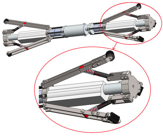
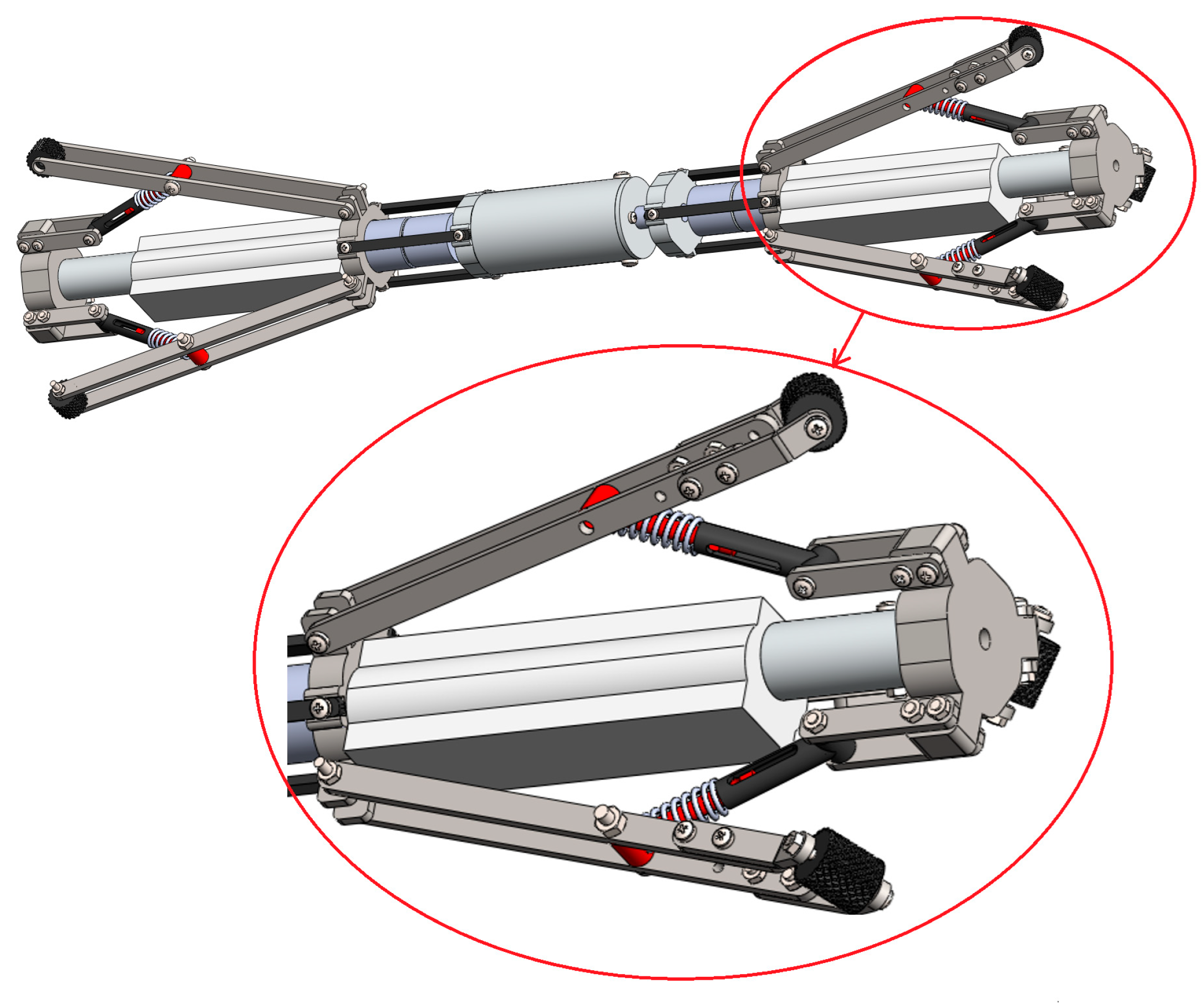
The proposed ASDIR shown in Figure 1 adopts a dual-module structure in which the front module contains three evenly spaced wheels mounted at a fixed tilt angle. These tilted wheels generate the screw-drive propulsion by converting gripping force into helical thrust. The rear module includes three non-tilted wheels that provide stabilizing reaction forces, suppressing body rotation, and maintaining axial alignment without contributing to propulsion. Both modules are mounted on compact ball-screw linear actuators that allow radial extension and retraction of the wheel arms. This differentiates the ASDIR from conventional passive SDRs, enabling the robot to adjust its effective diameter actively and regulate gripping force in real time. The central extension module further allows controlled axial contraction and expansion during stepwise maneuvers without compromising screw-drive propulsion.
Figure 1.
Isometric view of the proposed ASDIR and the front module with the three evenly spaced wheels mounted at a fixed tilt angle.
2.1.2. Gripping Arms and Spring Mechanism
Each wheel is mounted on a kinematically amplified linkage connected to a compression spring. When the radial actuator extends, the linkage pushes the wheel outward, compressing the spring and generating the gripping force required for traction. The linkage geometry allows small actuator displacements to produce relatively large wheel motions, improving responsiveness while keeping the actuators compact. This semi-compliant linkage–spring structure provides two functional advantages: (1) the ability to adapt to variations in pipe diameter through commanded radial expansion, and (2) the ability to generate and regulate controlled gripping forces needed for stable screw-drive locomotion. These characteristics form the basis for the ASDIR’s improved adaptability relative to traditional screw-drive robots.
2.1.3. Embedded Hall-Effect Force Sensing
To enable closed-loop gripping-force regulation, each arm incorporates a Hall-effect displacement sensor that measures the motion of a small magnet attached to the spring support. After calibration, the sensor output provides an accurate estimate of spring compression and thus the real-time gripping force. This sensing configuration offers several advantages: it is fully embedded within the arm, protected from contaminants, independent of friction-dependent motor-current estimation, and capable of detecting both free-space extension and post-contact compression. The inclusion of direct force sensing is central to the ASDIR’s ability to maintain safe and energy-efficient contact under changing pipe geometries.
2.1.4. Stator Frame and Structural Materials
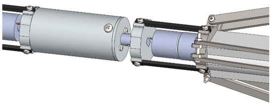
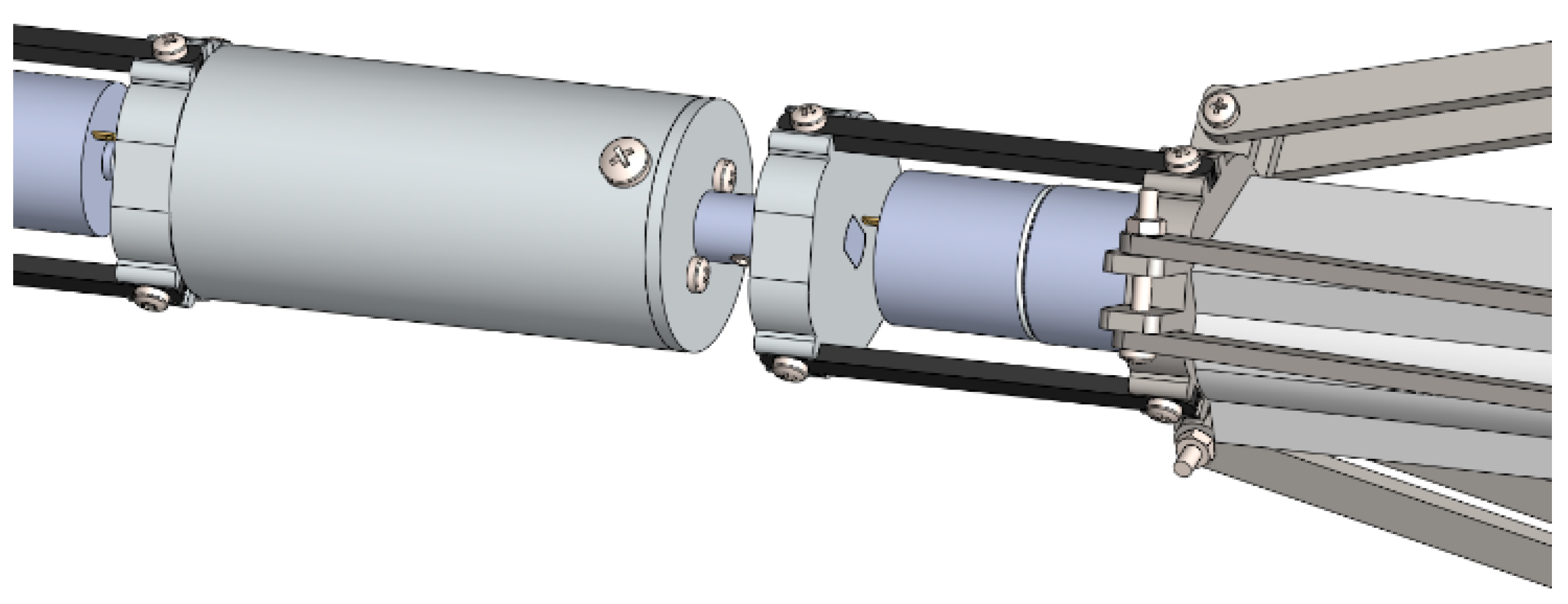
Figure 2 depicts the isometric view of the Stator Frame. The structural frame is constructed from lightweight aluminum alloy to achieve a high stiffness-to-weight ratio and corrosion resistance. The internal packaging accommodates actuators, sensors, electronics, and wiring while maintaining structural symmetry for balanced contact forces. The wheels of the rear module serve as the reaction stator, counteracting the rotational torque generated by the front module’s screw-drive motion. This ensures efficient thrust transfer and prevents body rotation, enabling smooth progression even during diameter transitions. All sensitive components are enclosed within a sealed housing suitable for harsh pipeline environments.
Figure 2.
Isometric view of the Stator Frame.
2.1.5. Tilt Angle as an Offline-Configurable Parameter
The wheel tilt angle determines the screw-drive kinematics, helical pitch, and conversion of gripping force into axial propulsion. In the ASDIR, this tilt angle is treated strictly as an offline-adjustable design parameter. Different wheel-mount geometries can be installed before deployment, but the angle remains fixed during operation. This approach improves mechanical robustness while allowing the tilt angle to be chosen through torque-limited optimization to guarantee traction with minimal required gripping force.
2.2. Modeling and Analysis
The ASDIR consists of a front tilted-wheel traction module and a rear straight-wheel stabilizing module, each containing three compliant arms actuated by a single ball-screw mechanism. The front wheels are mounted at a fixed, offline-selected tilt angle and generate screw-drive propulsion, while the rear wheels maintain radial stability without contributing to axial thrust. Each arm incorporates a compression spring and an embedded Hall-effect sensor that enables real-time estimation of gripping force.
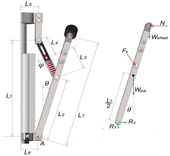
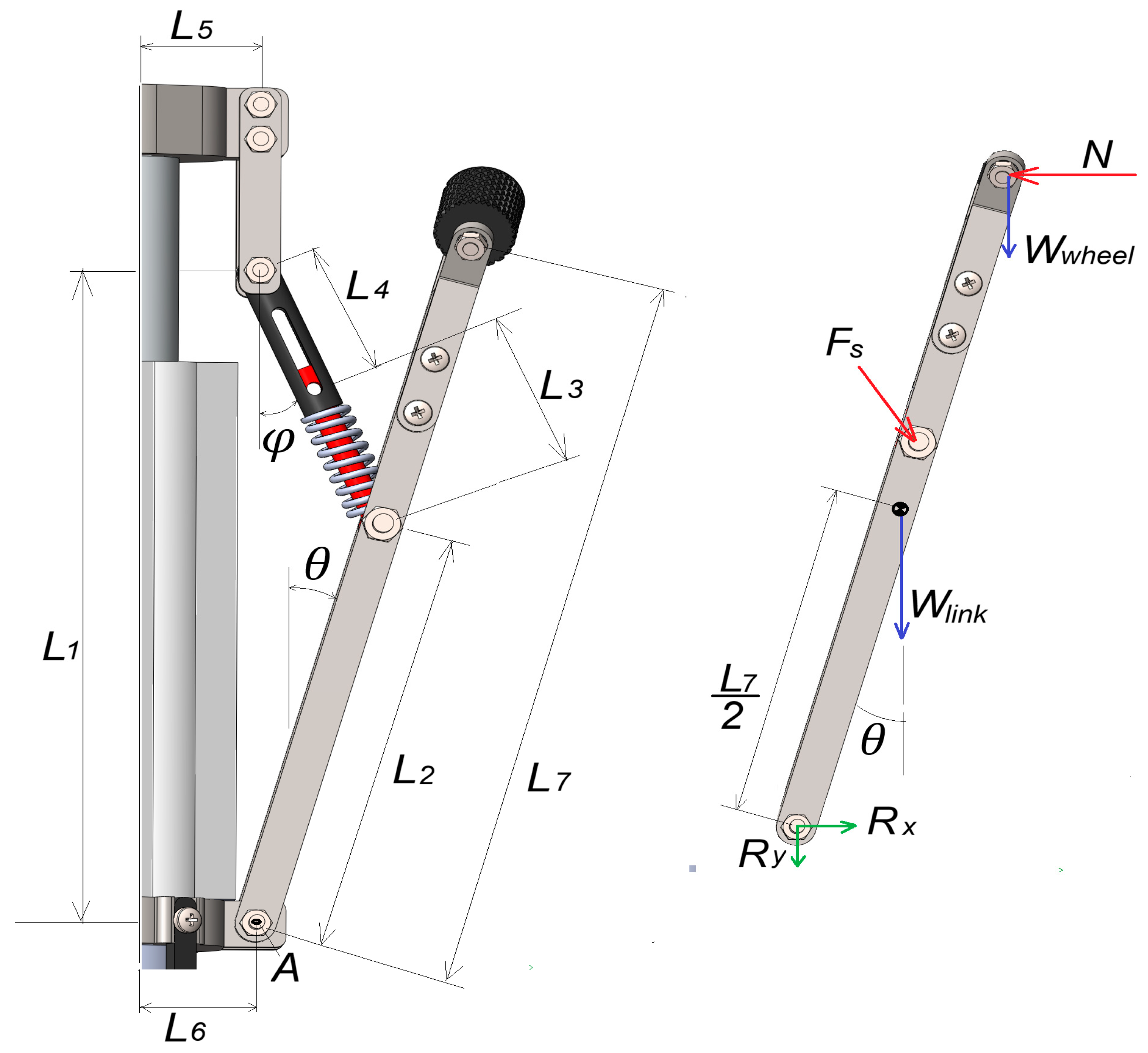
Referring to Figure 3, the left panel illustrates the geometric parameters, joint locations, spring orientation, and wheel mounting used in the kinematic and force analysis. The right panel presents the corresponding free-body diagram of a single gripping link, indicating the spring force, wheel–wall normal reaction, link weight, and base-joint reactions. The wheel–wall normal force is obtained from a static moment equilibrium of a single gripping arm about the base joint . The analysis accounts for the spring force applied at the linkage joint and the wheel–wall normal reaction. The effects of link and wheel weights are first included for completeness and subsequently neglected to obtain a simplified expression suitable for control design.
Figure 3.
Mechanical configuration of the ASDIR gripping arm and corresponding free-body diagram of a single linkage.
Let index the front and rear modules. Let denote the radial actuator displacement of the module at time t, the actuator–radius conversion gain (kinematic amplification), the resulting effective module radius, the nominal radius at , the spring compression. The radial kinematics are then written as
The internal pipe radius may deviate from its nominal value, and this deviation is now expressed as a geometric function of the axial position . After wheel–wall contact, the spring compression becomes
with the nominal pre-compression. The spring generates force along its axis
Taking moments about the base joint of the gripping arm shown in Figure 3 yields
where denotes the wheel–wall normal force of arm i in module m (three arms per module), is the arm inclination angle, and is the spring orientation angle. and are geometric lengths defined in Figure 3. and denote the wheel and link weights, respectively. Neglecting these weights, the normal force reduces to a scaled spring-force relationship:
where the geometric gain is given by
The gain represents a static force-transmission gain relating spring force to the wheel–wall normal contact force, and depends solely on the arm geometry and instantaneous configuration angles and is therefore treated as constant for a given mechanical design and operating posture.
Each module contains three identical arms, giving the total wheel–wall normal force
The Hall-effect sensor output is constant before contact and increases linearly with compression after contact:
where denotes the Hall-effect sensor output of the module at time , is the sensor output corresponding to the nominal (no additional compression) displacement, is the calibration gain of the Hall-effect sensor, represents the instantaneous spring compression of the module , and is the reference displacement at initial wall contact.
Thus, the controller obtains the compression estimate
where is the estimated spring compression used for gripping-force regulation, and the per-arm estimated normal force
Only the front tilted wheels produce propulsion. With wheel radius , wheel speed , and tilt angle the screw-drive kinematics give
The axial thrust produced by the front tilted wheels is
where is the axial propulsion force generated by the front traction module, is the effective friction coefficient between the wheel and the pipe wall, is the total normal force applied by the front module, and is the wheel tilt angle relative to the pipe axis.
While the rear wheels provide stabilizing frictional reactions that oppose body rotation and maintain axial alignment is
where represents the axial friction force associated with the rear stabilizing module, and is the total normal force applied by the rear module.
The maximum axial friction force that can be transmitted without slip, is given by
where denotes the total available axial friction force. The ASDIR drive torque produces axial thrust according to
For vertical upward motion, force feasibility and non-slip conditions must be satisfied to ensure stable climbing. Extensions to inclined pipes can be obtained by replacing Mg with the axial component of the gravitational load.
The drive-generated axial thrust must satisfy the force feasibility condition.
where is the robot mass and is gravitational acceleration.
where is a prescribed traction safety margin accounting for modeling uncertainty and friction variability.
Assuming symmetric gripping forces , substitution into (17) yields the minimum safe gripping force:
The assumption represents a nominal symmetric operation, since both modules use identical radial mechanisms and springs. Under ideal alignment and uniform pipe diameter, the clamping forces are therefore approximately equal. In practice, surface irregularities or mechanical tolerances may introduce moderate asymmetry; thus, the derived minimum safe clamping force should be interpreted as a conservative lower bound under symmetric conditions. Because the modules are independently actuated, asymmetries can be compensated through closed-loop regulation. The effects of asymmetric contact will be investigated experimentally.
In (17), since represents the total normal force of the front module (sum of the three arms), the corresponding per-arm value is given by
Using (4), the minimum required spring compression becomes
where is the minimum normal force required per arm.
The Hall-effect threshold ensures safe traction is
According to (2), spatial increases in pipe radius reduce the spring compression, and the worst-case deviation must therefore be compensated in the reference gripping force:
This reference ensures safe traction across varying diameters while avoiding unnecessary spring compression. The elastic energy stored in the spring is given by
This expression shows that limiting the steady-state spring compression directly reduces elastic energy storage and, consequently, decreases unnecessary actuator effort.
2.3. Gripping-Force Control Strategy
The ASDIR employs two independently controlled gripping modules: the front tilted-wheel traction module and the rear straight-wheel stabilizing module. Each is actuated by a single ball-screw mechanism driving three compliant arms in parallel. The aim of the control system is to regulate the gripping forces and so that the front module satisfies the nonslip condition in (17), while the rear module provides adequate radial stabilization. The tilt angle remains fixed during operation, having been selected offline.
The Hall-effect sensors embedded in each arm provide the spring-compression estimate via (9). The estimated per-arm normal force then follows from (10), and the total module force from (7). These estimated forces form the measurement signals used in the feedback loop. The desired gripping force for the front module is selected as the minimum safe value that compensates for both the traction requirement (17) and the largest expected pipe-radius deviation . This reference force is given directly by (22), and is denoted simply as . The rear module may use the same reference for symmetric gripping, although reduced values may be used in future implementations since the rear module contributes no propulsion.
Let be the actuator displacement of the module . The controller regulates the actuator velocity so that the estimated force tracks its reference. The force-tracking error is defined as
where is the minimum-safe reference force and .
A proportional–derivative (PD) controller governs the actuator velocity:
where and are the proportional and derivative gains for the module .
Because each ball-screw actuator has a finite speed limit, the velocity command is saturated as
where is the maximum allowable actuator velocity.
Through (2) and (4), any increase in pipe radius along the robot’s displacement reduces the spring compression and, consequently, the gripping force. As a result, becomes positive, and the controller extends to restore the force. Conversely, a decrease in pipe radius produces a negative error, causing the controller to retract the actuator to avoid excessive gripping. This ensures that the front module provides the minimum normal force required to satisfy (17), while the rear module maintains robot stability and prevents rotational motion about the pipe axis. The two controllers operate independently, guaranteeing that front-module traction and rear-module stability are achieved simultaneously. Because is not actuated, no tilt-angle control appears in the closed-loop dynamics. The resulting control architecture is low order, as it regulates a single force variable through the actuator velocity in (25) and (26), while pipe-diameter variations enter as an additive disturbance through (2). Selecting the reference force according to the minimum-safe condition in (22) limits spring compression and actuator effort, and the nonslip constraint in (17) guarantees traction. Together, these properties enable reliable and energy-aware screw-drive locomotion across variable pipe diameters.
2.4. Simulation Framework
The simulation framework is designed to validate the ASDIR’s mechanical model and gripping-force controller under controlled but realistic operating conditions. It reproduces the coupled behavior of the radial actuators, spring–linkage mechanics, Hall-effect sensing, PD force regulation, and screw-drive traction when the robot experiences a smooth change in pipe diameter from 4.5 in to 5.0 in, with additional stochastic geometric and sensing disturbances. All force-generation and traction relations follow directly from the analytical expressions derived in Section 2.2 and Section 2.3, and are used to evaluate safety and traction performance. The key performance metric related to safety is the traction margin, defined as
which represents the difference between the available axial friction capacity and the required axial load. A strictly positive margin indicates safe screw-drive operation.
The pipe geometry is modeled as a spatial variation in the internal radius along the axial coordinate . A smooth diameter transition from 4.5 in to 5.0 in is represented by a linear axial radius gradient over a finite ramp length . The corresponding radius deviation is defined as
where is the maximum radius increase over the transition. Outside this axial interval, the radius deviation remains constant. Accordingly, the disturbance applied in the simulation is evaluated along the robot’s forward motion as , with
where denotes the start of the diameter-transition region.
Manufacturing tolerances and local wall irregularities are modeled by adding a bounded random fluctuation to the nominal deviation:
where is a zero-mean stochastic process with amplitude limited to a small percentage of the initial radius, for example of .
At each time step, the true pipe radius is defined as
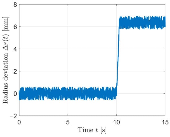
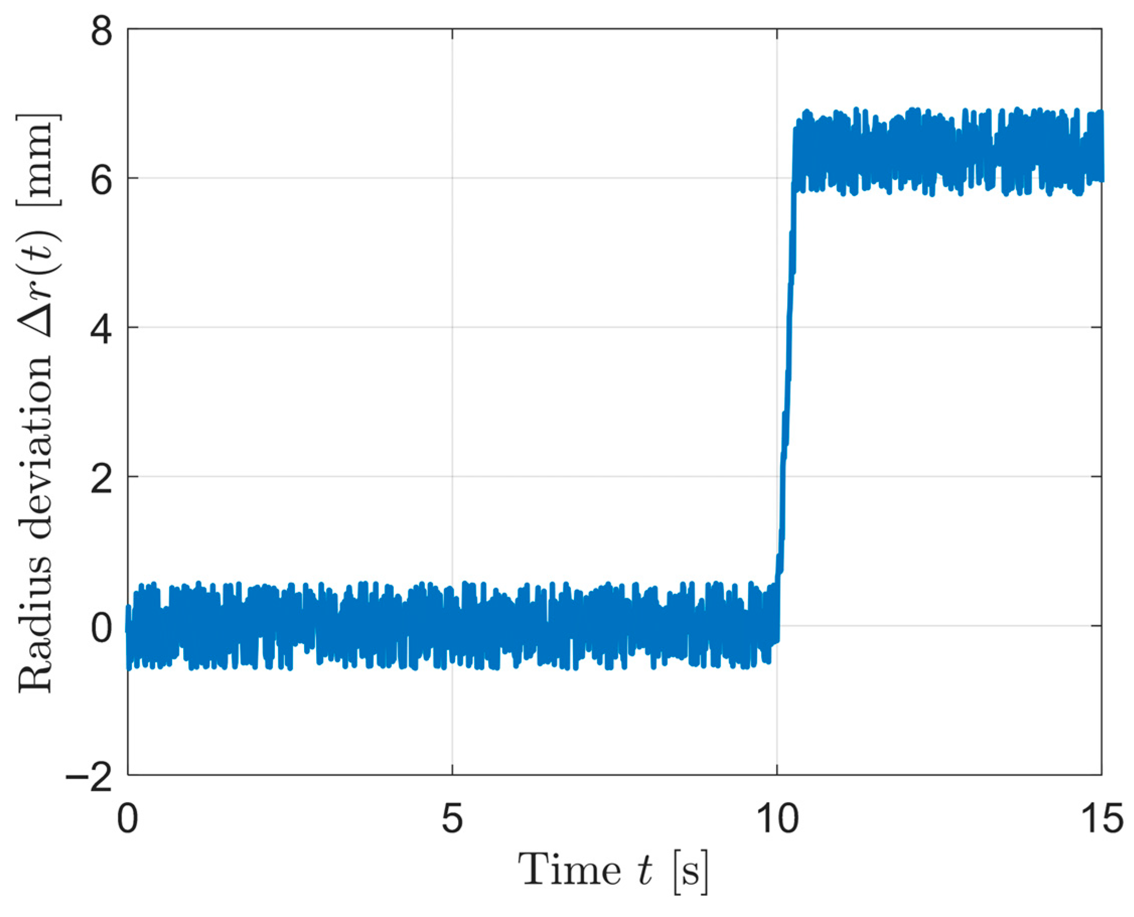
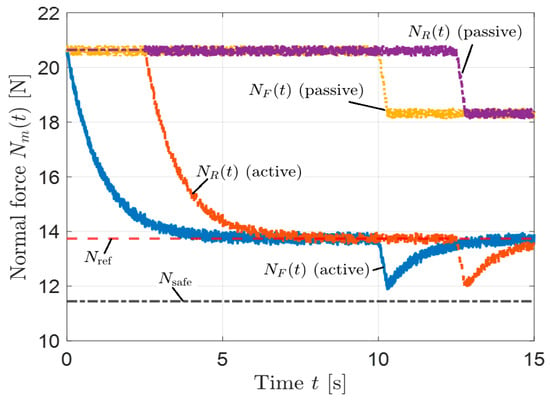
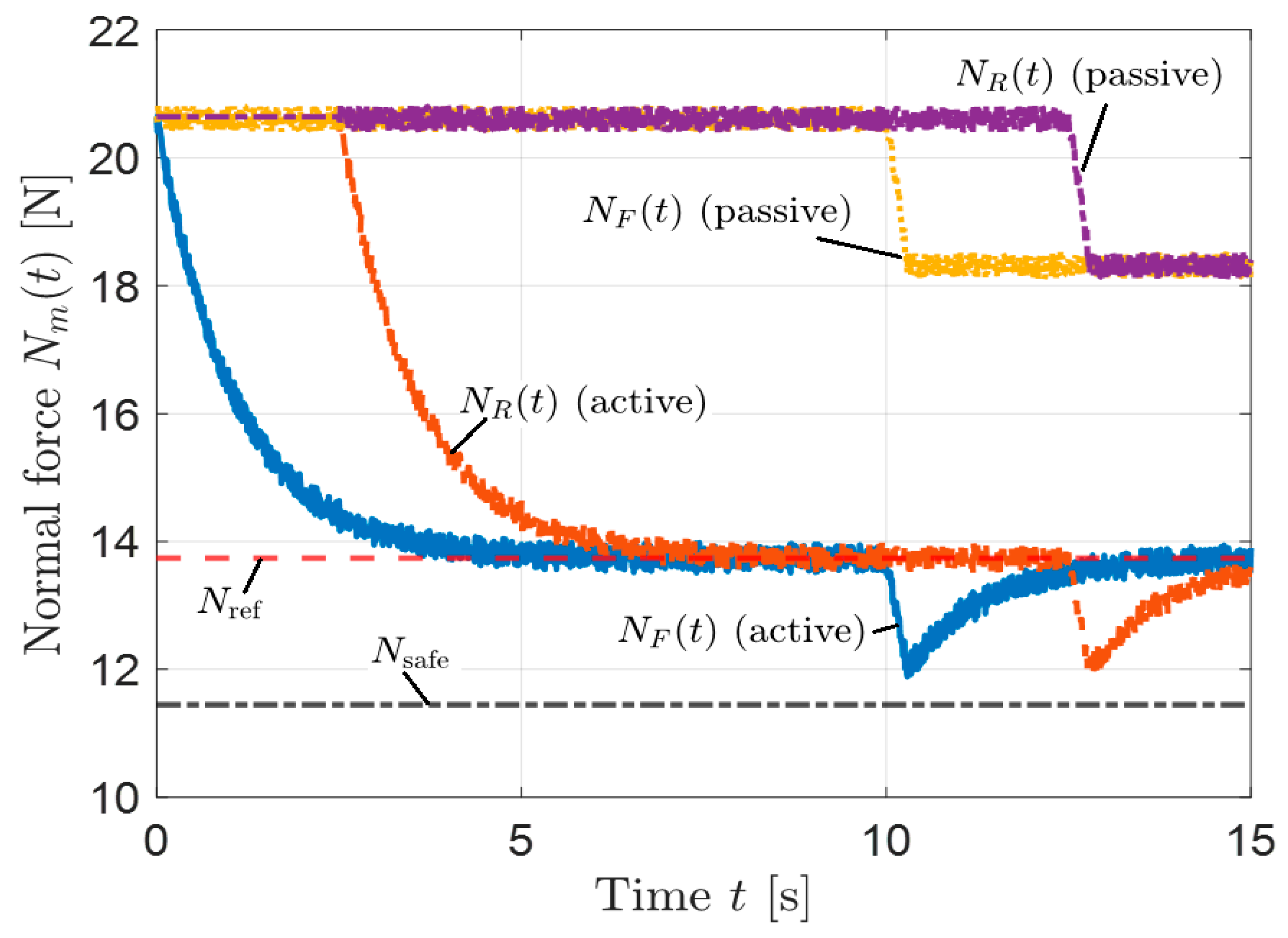
where is the nominal initial pipe radius, represents the deterministic diameter transition defined in (28) and (29), and denotes a stochastic disturbance term modeling measurement noise or minor surface irregularities. The resulting pipe-radius profile used in the simulation is illustrated in Figure 4. The corresponding front and rear gripping-force responses under this diameter transition are shown in Figure 5, where the reference force and the minimum safe force are indicated. The elevated initial force corresponds to the preload-dominated condition when the robot is fully confined within the nominal pipe section. As the diameter transition begins, the controller regulates the force toward .
Figure 4.
Spatial radius deviation profile during the 4.5 in–5.0 in diameter transition.
Figure 5.
Front and rear gripping forces during the simulated pipe diameter transition.
For each module , the spring compression is computed from and using (2), and the corresponding normal forces and follow from (4) and (7). The Hall-effect sensing model (8)–(10) can be extended with an additive force-estimate noise , so that the controller uses a noisy force estimate
where is a bounded zero-mean noise process representing sensor offset and gain mismatch. In the simulations, is chosen so that its amplitude does not exceed a small fraction of the reference gripping force. The controller computes the tracking error from the reference force given by (22) and the estimated force, that is, as in (24).
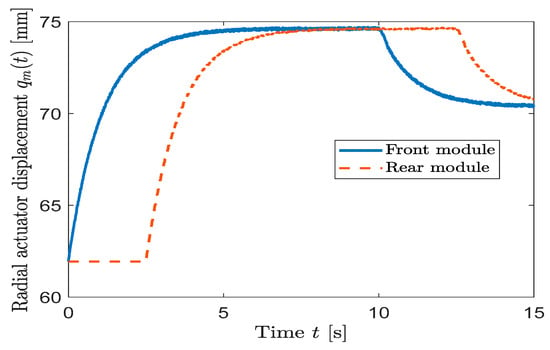
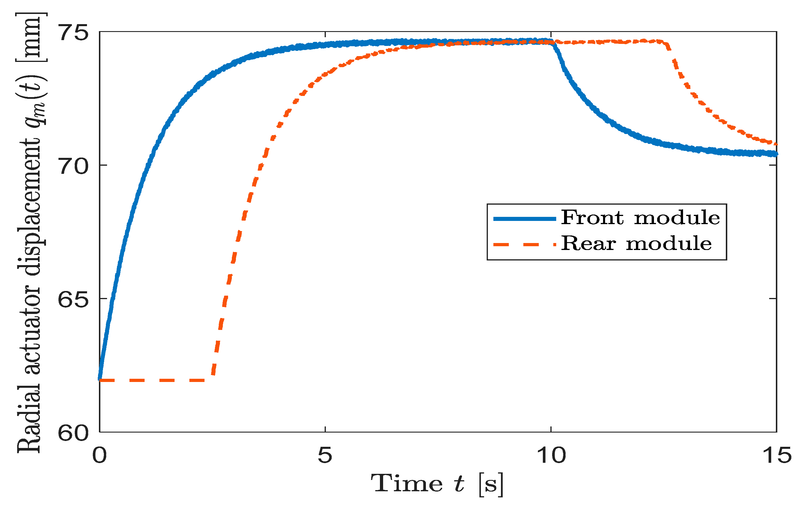
The actuator velocity is obtained from the PD control law (25) with saturation (26). The resulting actuator displacement trajectories and are plotted in Figure 6, which shows that the rear-module displacement follows the front-module displacement with a time shift corresponding to the axial separation between modules. Both actuators obey the same control law, and the time shift reflects that the front module encounters the diameter transition earlier during forward motion. The actuator displacements are then numerically integrated in time using a fixed integration step, typically s. At each step, the simulation logs the true forces and , the estimated forces, the actuator positions, the pipe-radius profile, and the traction margin (27).
Figure 6.
Radial actuator displacements of the front and rear modules during the diameter transition.
A focused case study examines the ASDIR’s response as it moves from a constant 4.5 in pipe section, through the 4.5–5.0 in expansion, into a constant 5.0 in section. The diameter transition begins when the robot reaches the axial position . With constant axial velocity , the corresponding time is . The radius increases according to the spatial slope and reaches the full 5.0-in diameter at (time ). The simulation is typically run until s to capture pre-transition, transition, and post-transition behavior. The parameters listed in Table 2 (robot mass, friction coefficient, spring stiffness, amplification ratio, tilt angle, PD gains, and actuator limits) are used in all runs, and the same simulation framework is applied to both front and rear modules. To make the implementation unambiguous, the core simulation procedure can be summarized as the algorithm shown in Algorithm 1. This simulation framework allows the evaluation of gripping-force tracking, actuator usage, and traction safety under a wide range of diameter profiles and disturbance conditions.
Table 2.
Parameters Used in the ASDIR Simulation.
The disturbance model employed in this study focuses on structured diameter variation and bounded stochastic friction uncertainty representative of clean gas and water transmission pipelines. Such systems are typically manufactured with relatively smooth internal surfaces and limited roughness compared to sewer or debris-intensive environments. Severe corrosion, heavy contamination, or highly non-circular structural deformation are beyond the scope of the present simulation study. The integrated spring compliance and the prescribed positive traction safety margin in (17) are intended to mitigate moderate surface irregularities and friction variability expected under standard operational conditions.
| Algorithm 1: ASDIR gripping-force simulation |
|
2.5. Experimental Validation Plan
The experimental program is intended to validate the key elements of the proposed ASDIR concept following the modeling, control, and simulation results presented in Section 2.2, Section 2.3 and Section 2.4. At the current stage, no experimental measurements have been conducted. Instead, this section outlines the planned experimental procedures that will be used in the next phase to verify the sensing model, the gripping-force predictions, and the closed-loop control behavior derived in this paper. Full experimental validation, including extended in-pipe trials, will be reported in future work.
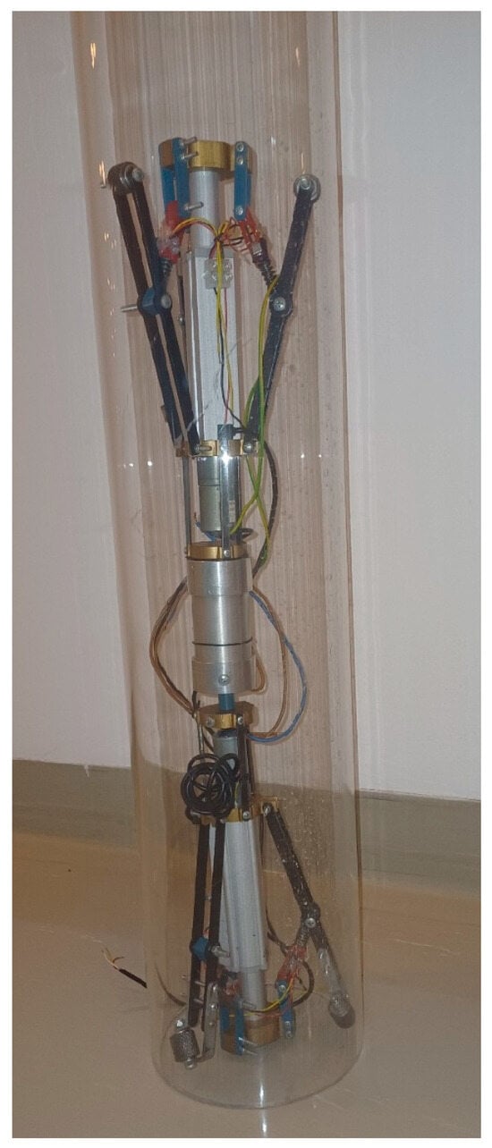
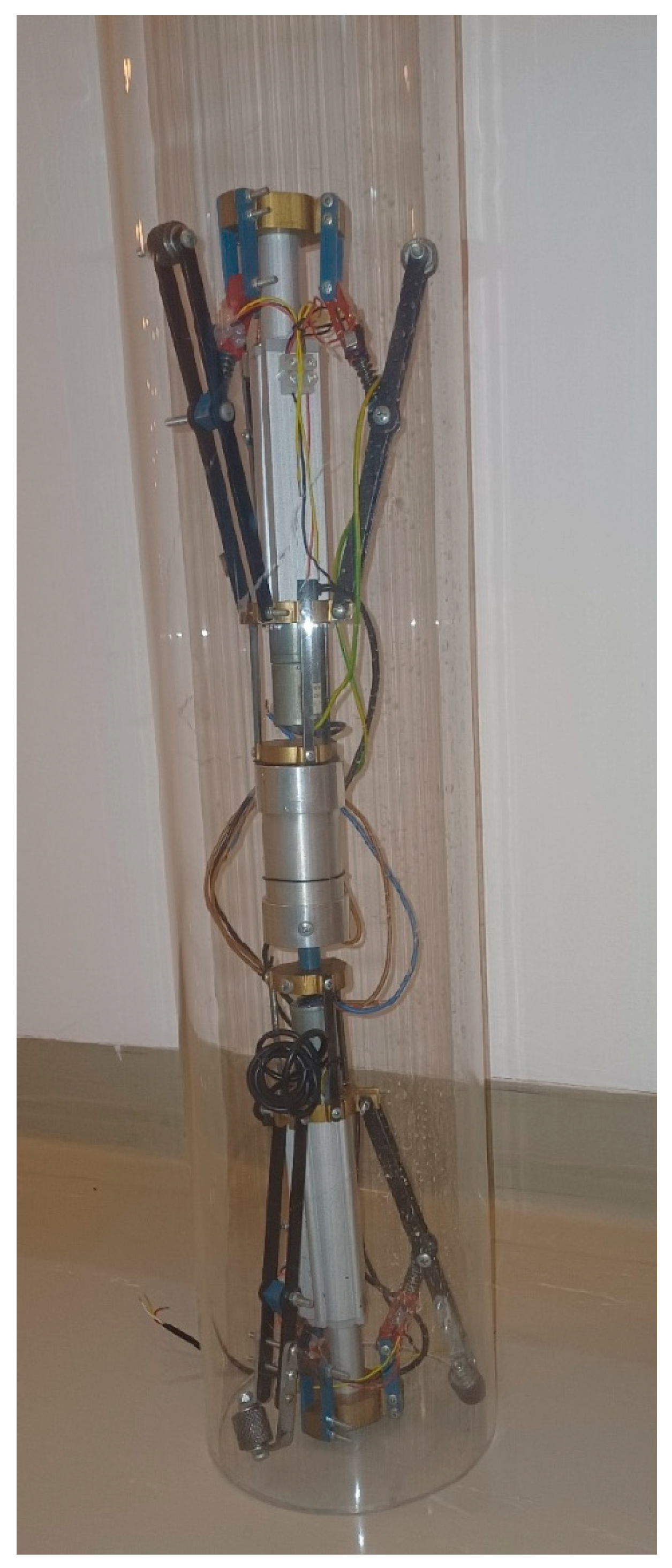
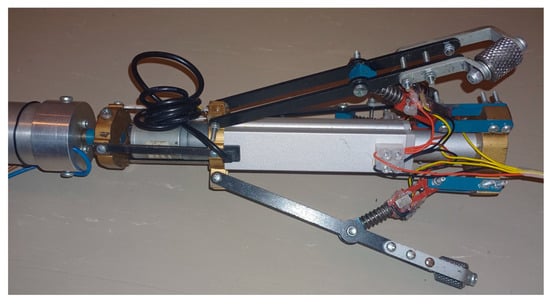
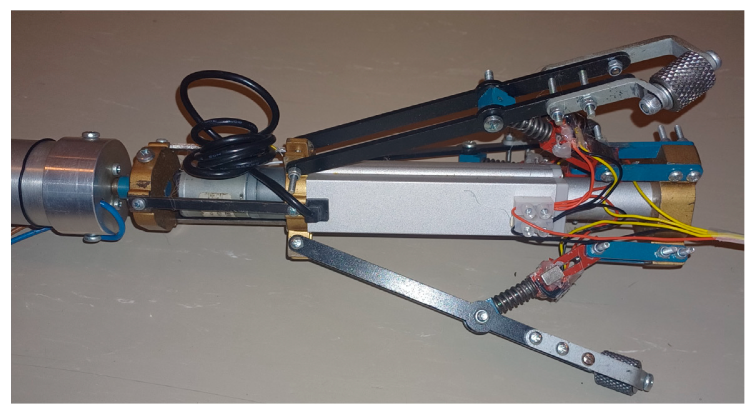
A physical prototype of the ASDIR has been fabricated, as shown in Figure 7, to support the forthcoming experimental campaign. The robot consists of a front tilted-wheel traction module and a rear straight-wheel stabilizing module, each comprising three identical arms actuated by a ball-screw mechanism and pre-loaded compression springs instrumented with Hall-effect displacement sensors, as shown in Figure 8. The mechanical geometry, link lengths, tilt angle, and spring parameters match those used in the modeling and simulation framework, ensuring consistency between the analytical, numerical, and hardware representations.
Figure 7.
Fabricated ASDIR hardware prototype mounted inside a transparent pipe for planned experimental validation.
Figure 8.
Close-up view of an ASDIR radial gripping arm assembly with front tilted wheels, ball-screw actuation, and Hall-effect sensing.
The planned experimental setup includes a transparent PVC pipe segment of known inner diameter (D1 = 4.5 in) mounted on a rigid frame, a load cell and linear translation stage for controlled force application during sensor calibration, a DC power supply and motor drivers for the ball-screw actuators, and a data-acquisition system for recording Hall-sensor outputs and actuator states. This setup is designed to directly evaluate the assumptions used in the force estimation and control models. To validate the Hall-effect sensing model defined in (8) and (9), a single arm will be tested outside the pipe environment. The arm will be rigidly clamped at its base, and the wheel will be pressed against a rigid surface connected to a calibrated load cell. The actuator will be commanded through quasi-static displacement steps over the expected operating range. At each step, the spring compression δₘ will be measured using a reference indicator, while the load cell provides the true normal force, and the Hall sensor output sₘ is recorded. These data will be used to identify the sensor gain and offset and to verify the linear mapping between measured displacement and gripping force assumed in the control design.
The minimum safe gripping force predicted by (18)–(21) will be evaluated in a vertical pipe configuration consistent with the modeling assumptions of Section 2.2. In the planned tests, the ASDIR will be positioned so that all wheels contact the pipe wall, and the front-module gripping force will be gradually increased while monitoring sensor outputs. The lowest force at which slip-free motion can be achieved over a short axial displacement will provide an experimental estimate of the minimum safe gripping force, which will be compared against the theoretical prediction. Additional tests with added payloads are planned to assess robustness margins.
Finally, short-range locomotion tests are planned to examine the qualitative behavior of the force controller described in Section 2.3. In these tests, the ASDIR will be commanded to move inside a horizontal pipe using the PD gains obtained from simulation. Localized diameter perturbations will be introduced using thin shims attached to the inner pipe wall, creating positive Δr disturbances. The resulting actuator responses and estimated gripping forces will be compared qualitatively with the simulated results to assess consistency.
The fabricated prototype demonstrates the feasibility of the proposed architecture, and the planned experiments will be used in future work to validate the sensing, force regulation, and screw-drive locomotion performance of the ASDIR.
3. Results
The performance of the ASDIR is evaluated through numerical simulations using the framework described in Section 2.4. The simulation considers a pipe transitioning from to , with the diameter ramp applied over approximately 1.67 s at a slope of . For , the robot operates in the nominal diameter region with . After , the diameter increases linearly until reaching , after which it remains constant. Both the front and rear modules are driven by the PD controller of Section 2.3 using the reference gripping force defined in (22) and the actuator saturation limits in (26). Small geometric fluctuations and sensor noise are introduced as described in (30) and (31). During the initial constant-diameter phase, the gripping forces of both modules converge to their respective reference values . The force-tracking error decays rapidly, indicating that the selected PD gains provide sufficient damping without oscillation or overshoot. In steady state, actuator velocities approach zero, demonstrating that the radial actuation mechanism requires minimal motion once the desired force level is achieved. The traction margin computed using (27) remains strictly positive throughout this phase, confirming that the minimum safe gripping force derived from (18)–(21) is sufficient under nominal conditions.
When the pipe diameter begins to increase, the effective pipe radius rises, reducing the spring compression and causing a transient decrease in the normal force. This effect is immediately reflected in the simulated Hall-effect force estimates , consistent with the sensing model in (9) and (10). The PD controller responds by increasing the actuator displacement , thereby restoring the gripping force to its reference value. Both modules compensate smoothly for the radius increase without instability. The front module maintains the traction requirement throughout the transition, and although a small transient dip in occurs during the steepest portion of the diameter ramp, the force remains above the threshold required by (17), as evidenced by the positive traction margin.
The contrast between active and passive behavior is most pronounced during the diameter ramp. The passive open-loop baseline (fixed preload without feedback) exhibits a force drop of approximately 2–3 N as the pipe radius increases, bringing the force closer to the minimum-safe threshold . In contrast, the active closed-loop regulation confines the force deviation to within approximately ±0.2–0.3 N around the reference and restores it within about 1 s after the disturbance onset. Furthermore, in the constant 4.5″ section prior to the ramp, the passive configuration operates with a preload roughly 6–7 N above the minimum-safe requirement, whereas the active controller regulates the force near the analytically derived minimum-safe value. These quantitative differences demonstrate improved disturbance rejection and reduced steady-state over compression under closed-loop regulation.
The rear module exhibits a similar response with reduced actuator activity, reflecting its stabilizing role and lower control gains. Once the pipe diameter stabilizes at in, the gripping forces again converge to , and actuator motion diminishes.
4. Discussion
The simulation results demonstrate the controller’s ability to adapt to continuous, step-free geometric variations without sustained oscillations or excessive actuation. This behavior confirms the theoretical prediction that the front module applies only the minimum force required for nonslip operation, while additional energy expenditure occurs primarily during transient diameter changes when work must be performed against the springs. These results substantiate the internal consistency of the proposed modeling, sensing, and control framework, demonstrating that closed-loop gripping-force regulation maintains traction safety under realistic pipe-diameter variations while minimizing actuator motion.
In comparison with the passive open-loop baseline, the active regulation strategy exhibits improved disturbance rejection during diameter transitions. The passive configuration, representative of conventional fixed-preload designs without feedback control, shows a measurable reduction in gripping force during pipe expansion and sustained over-preload in nominal sections. By contrast, the proposed closed-loop approach confines force deviations within a narrow band around the analytically derived minimum-safe reference and restores nominal operation rapidly after disturbance onset. This direct comparison underscores the practical benefit of integrating direct force sensing with feedback regulation.
From an energy-efficiency perspective, traditional passive SDR systems rely on conservative mechanical preload to ensure traction under uncertain geometric conditions. Such a preload inherently results in persistent spring overcompression and unnecessary actuator effort. By regulating the gripping force toward the minimum-safe requirement, the proposed strategy reduces steady-state spring compression and limits elastic energy storage. Consequently, actuator work is concentrated primarily during geometric transitions rather than sustained throughout operation. A quantitative comparison of cumulative actuator work and energy consumption between passive and active configurations will be conducted in future extended simulations and laboratory experiments.
The transition from simulation to physical experimentation introduces additional practical considerations. Real industrial pipelines may exhibit surface contamination, friction variability, localized corrosion, or compliant wall behavior not fully captured in the present disturbance model. Although the integrated spring compliance and prescribed traction safety margin mitigate moderate uncertainty, more severe environmental conditions may require adaptive gain tuning or friction estimation strategies. Furthermore, actuator backlash, structural tolerances, and Hall-effect sensor calibration under dynamic loading may influence real-world performance and must be assessed experimentally.
Experimental validation using the fabricated prototype is therefore planned as the next stage of development to empirically verify force-tracking accuracy, traction-margin preservation, and expected energy-efficiency improvements under representative operating conditions.
5. Conclusions
This work presented the design, analytical modeling, and simulation-based validation of an Adaptive Screw-Drive In-Pipe Robot integrating adjustable radial geometry, embedded Hall-effect force sensing, and closed-loop gripping-force regulation. A unified mechanical–geometric framework was developed to describe the relationship between actuator displacement, spring compression, wheel–wall contact forces, and pipe-diameter variation. From this formulation, a traction-safety condition was derived to determine the minimum gripping force required to prevent slip under geometric disturbances.
Comparative simulation against a passive fixed-preload baseline demonstrated that closed-loop regulation improves disturbance rejection during diameter transitions, maintains a positive traction margin, and reduces steady-state over compression. As discussed, these characteristics indicate potential advantages in force stability and energy utilization relative to conventional open-loop configurations.
The analysis further highlighted practical considerations relevant to implementation, including friction variability, geometric irregularities, actuator limitations, and sensor calibration under dynamic loading. These aspects define important directions for further validation and refinement of the proposed approach.
The present study is limited to analytical development and simulation-based assessment. Experimental evaluation using the fabricated prototype constitutes the next stage of research to empirically verify force-tracking performance, traction safety, and the anticipated energy-related benefits in controlled laboratory pipe environments.
Author Contributions
Conceptualization, R.Z.; Methodology, R.Z.; Formal analysis, R.Z. and A.S.A.; Writing—review & editing, A.S.A. All authors have read and agreed to the published version of the manuscript.
Funding
This work was supported by Petroleum Development Oman, and Ejaad Platform under the grant CR/ENG/MIED/22/01.
Data Availability Statement
The original contributions presented in this study are included in the article. Further inquiries can be directed to the corresponding author.
Conflicts of Interest
The authors declare no conflict of interest.
Abbreviations
The following abbreviations are used in this manuscript:
| ASDIR | Adaptive Screw-Drive In-Pipe Robot |
| SDR | Screw-Drive Robot |
| PD | Proportional–Derivative |
| DoF | Degree of Freedom |
| PVC | Polyvinyl Chloride |
References
- Zeid, A.; Al-Yahmedi, A.; Zaier, R.; Bahadur, I. Multi-objective design optimization of an in-pipe inspection robot. Frankl. Open 2024, 6, 100071. [Google Scholar] [CrossRef] [Scilit]
- Ab Rashid, M.Z.; Mohd Yakub, M.F.; Zaki bin Shaikh Salim, S.A.; Mamat, N.; Syed Mohd Putra, S.M.; Roslan, S.A. Modeling of the in-pipe inspection robot: A comprehensive review. Ocean Eng. 2020, 203, 107206. [Google Scholar] [CrossRef] [Scilit]
- Jeon, K.W.; Jung, E.J.; Bae, J.H.; Park, S.H.; Kim, J.J.; Chung, G.; Chung, H.-J.; Yi, H. Development of an In-Pipe Inspection Robot for Large-Diameter Water Pipes. Sensors 2024, 24, 3470. [Google Scholar] [CrossRef] [Scilit] [PubMed]
- Nguyen, T.L.; Blight, A.; Pickering, A.; Jackson-Mills, G.; Barber, A.R.; Boyle, J.H.; Richardson, R.; Dogar, M.; Cohen, N. Autonomous control for miniaturized mobile robots in unknown pipe networks. Front. Robot. AI 2022, 9, 997415. [Google Scholar] [CrossRef] [Scilit] [PubMed]
- Gargade, A.; Ohol, S. In-pipe Inspection Robot for Varying Pipe Sizes. Int. J. Eng. Sci. 2022, 14, 140–147. [Google Scholar] [CrossRef] [Scilit]
- Yin, J.; Liu, X.; Wang, Y.; Wang, Y. Design and motion mechanism analysis of screw-driven in-pipe inspection robot based on novel adapting mechanism. Robotica 2024, 42, 1297–1319. [Google Scholar] [CrossRef] [Scilit]
- Li, T.; Liu, K.; Liu, H.; Cui, X.; Li, B.; Wang, Y. Rapid design of a screw drive in-pipe robot based on parameterized simulation technology. Simulation 2019, 95, 659–670. [Google Scholar] [CrossRef] [Scilit]
- Elankavi, R.S.; Dinakaran, D.; Chetty, R.M.K.; Ramya, M.M.; Samuel, D.G.H. A Review on Wheeled Type In-Pipe Inspection Robot. Int. J. Mech. Eng. Robot. Res. 2022, 11, 745–754. [Google Scholar] [CrossRef] [Scilit]
- Jang, H.; Kim, H.M.; Lee, M.S.; Song, Y.H.; Lee, Y.; Ryew, W.R.; Choi, H.R. Development of modularized in-pipe inspection robotic system: MRINSPECT VII+. Robotica 2022, 40, 1361–1384. [Google Scholar] [CrossRef] [Scilit]
- Inbar, O.; Zarrouk, D. Analysis of climbing in circular and rectangular pipes with a reconfigurable sprawling robot. Mech. Mach. Theory 2022, 173, 104832. [Google Scholar] [CrossRef] [Scilit]
- Zeid, A.; Al-Yahmedi, A.; Zaier, R.; Bahadur, I. Design and Control of a Diameter-Adaptable In-Pipe Inspection Robot. In Proceedings of the 2023 IEEE 4th International Multidisciplinary Conference on Engineering Technology, IMCET 2023, Beirut, Lebanon, 14–17 December 2023. [Google Scholar] [CrossRef] [Scilit]
- Ling, Z.; Chen, Y.; Tang, J.; Zheng, M. Development and Design of Self-Adaptive Variable Diameter Robot for In-Pipe Inspection. In IOP Conference Series: Materials Science and Engineering; IOP Publishing Ltd.: Bristol, UK, 2020. [Google Scholar] [CrossRef] [Scilit]
- Park, J.; Luong, T.; Moon, H. Development of a Wheel-Type In-Pipe Robot Using Continuously Variable Transmission Mechanisms for Pipeline Inspection. Biomimetics 2024, 9, 113. [Google Scholar] [CrossRef] [Scilit]
- Zhang, Y.; Yan, G. In-pipe inspection robot with active pipe-diameter adaptability and automatic tractive force adjusting. Mech. Mach. Theory 2007, 42, 1618–1631. [Google Scholar] [CrossRef] [Scilit]
- Liu, B.; Wu, Z.; Wang, P.; He, L.; Yang, L.; Lian, Z.; Liu, T. Quantization of magnetic flux leakage internal detection signals for composite defects of gas and oil pipelines. Energy Rep. 2023, 9, 5899–5914. [Google Scholar] [CrossRef] [Scilit]
- Li, P.; Tang, M.; Lyu, C.; Fang, M.; Duan, X.; Liu, Y. Design and analysis of a novel active screw-drive pipe robot. Adv. Mech. Eng. 2018, 10, 1687814018801384. [Google Scholar] [CrossRef] [Scilit]
- Li, P.; Ma, S.; Lyu, C.; Jiang, X.; Liu, Y. Energy-efficient control of a screw-drive pipe robot with consideration of actuator’s characteristics. Robot. Biomim. 2016, 3, 11. [Google Scholar] [CrossRef] [Scilit] [PubMed]
- Agarwal, R.; Bhatti, G.; Singh, R.R.; Indragandhi, V.; Suresh, V.; Jasinska, L.; Leonowicz, Z. Intelligent Fault Detection in Hall-Effect Rotary Encoders for Industry 4.0 Applications. Electronics 2022, 11, 3633. [Google Scholar] [CrossRef] [Scilit]

Disclaimer/Publisher’s Note: The statements, opinions and data contained in all publications are solely those of the individual author(s) and contributor(s) and not of MDPI and/or the editor(s). MDPI and/or the editor(s) disclaim responsibility for any injury to people or property resulting from any ideas, methods, instructions or products referred to in the content. |
© 2026 by the authors. Licensee MDPI, Basel, Switzerland. This article is an open access article distributed under the terms and conditions of the Creative Commons Attribution (CC BY) license.