


Abstract
As a next-generation serial communication protocol employed in automotive electronics and industrial control domains, Controller Area Network with Flexible Data-Rate (CAN-FD) enhances communication efficiency via the introduction of a dual-rate transmission mechanism, yet it still inherits the security vulnerabilities of traditional CAN networks. To enhance the security of node identity authentication in CAN-FD networks—a critical prerequisite for secure communication—we present an electronic control unit (ECU) authentication scheme that utilizes voltage hardware fingerprints (VHFs) as the core identity credential. Specifically, a single frame of data is utilized to integrate the control field’s voltage characteristics and data field’s edges, forming stable and distinguishable hardware fingerprints. We also analyze the VHF offset characteristics under typical spoofing attacks and wire-tapping attacks, and then propose a lightweight vehicle intrusion detection system (VIDS) scheme to identify attack scenarios and locate the compromised ECU in CAN-FD networks. Lastly, we conducted research on and discussed other VHF-influencing factors and put forward detailed specific solutions. Attack tests are conducted under four representative scenarios, namely substitution attack, masquerade attack, injection attack, and wire-tapping attack. The findings reveal that our scheme can not only accurately distinguish between various CAN-FD nodes but also identify specific attack types in real time. In detail, a single-frame node recognition rate exceeding 99% is achieved in approximately 2 ms, and in experiments covering multiple attack scenarios on this six-node prototype system, 100% recognition accuracy for attack types is realized in approximately 500 ms.
1. Introduction
With the rapid advancement of intelligent and connected technologies, modern automobiles have transcended the paradigm of traditional mechanical devices, evolving into highly integrated electronic control systems (ECSs). Within a vehicle, a multitude of electronic control units (ECUs) are interconnected via in-vehicle networks (IVNs)—including Controller Area Network (CAN), Local Interconnect Network (LIN), FlexRay, and Ethernet—each undertaking core functional modules such as vehicle dynamic control, telematics, advanced driver assistance systems (ADAS), and in-vehicle infotainment (IVI) [1,2,3]. As the de facto standard for IVNs, CAN (ISO 11898) [4] has been widely deployed in automotive and industrial domains for over three decades, with its primary application scenario being the interconnection of systems critical to functional safety (e.g., brake control and power steering systems) [5].
However, the proliferation of external interfaces in intelligent connected vehicles (ICVs)—such as Bluetooth, cellular communication (4G/5G), and WiFi—has shattered the closed nature of traditional in-vehicle networks, exposing CAN networks to increasingly severe security vulnerabilities [6,7]. A landmark case that underscored such risks occurred in 2015: researchers remotely hijacked a Jeep Cherokee traveling on a highway by exploiting a vulnerability in its telematics unit to inject malicious data packets into the CAN network [8]. This attack enabled unauthorized control of critical functions (e.g., engine shutdown and brake failure), ultimately prompting the recall of 1.4 million vehicles of the same model and highlighting the urgent need for CAN network security enhancement.
With the limitations of the CAN bus, such as short data and slow speed, becoming more prominent, CAN-FD (Flexible Data-rate), as the new de facto standard for in-vehicle communication networks, is rapidly entering the public eye and being widely applied in the automotive and other industrial fields [4]. Inheriting the broadcast feature and lacking built-in authentication and encryption mechanisms from its inception, the CAN-FD bus remains vulnerable. Attackers can still obtain access to the bus through physical access (e.g., OBD-II interface, USB interface) or remote vulnerabilities, and then tamper with data, inject malicious messages, and even control key vehicle functions [9]. Therefore, ensuring the communication security of the CAN-FD bus has become a core prerequisite for the development of autonomous driving and intelligent vehicles [10,11].
The essence of an intrusion detection system (IDS) is to monitor the content, cycle, or inherent characteristics of messages and verify whether they have any significant changes. Since they are constant and predictable in the vehicle network, IDS is proven to be feasible in most cases [12,13,14,15]. Currently, there are various types of IDSs. We classifies IDS technology into two major categories: parameter monitoring-based method (PMBM) [16,17] and hardware fingerprint-based method (HFBM) [18,19,20]. PMBM discovers attacks by observing and comparing network parameters including (i) message frequency [15,21], (ii) remote frame [16,22]. However, PMBM may be ineffective for unknown security threats, and the corresponding parameters vary in different vehicle networks. As the IVN gradually integrates with external networks, attacks on cars will show increasing uncertainty and complexity.
Owing to the inherent physical characteristics of CAN transmission circuits—including subtle variations in impedance, signal attenuation, and transceiver response time—each ECU on an in-vehicle CAN network generates a unique CAN hardware fingerprint. Unlike PMBMs, the HFBM addresses these above limitations by shifting defense to the physical layer. First, for unknown threats, HFBM acts as a physical-layer whitelist: malicious messages must be transmitted by a physical transceiver, and mismatched electrical profiles with legitimate ECU fingerprints trigger alerts, making it robust against unknown software exploits. Second, regarding parameter variability, HFBM eliminates the need to manually tune logical rules across different vehicle models.
Accordingly, extracting clock or voltage characteristics from CAN signals for ECU authentication represents a highly promising HFBM. The intrusion detection technology based on clock characteristics is also called CIDS [23,24,25]. However, this method cannot detect and trace non-periodic signals, and attackers can monitor the clock skew of legitimate nodes and their own by the same method. By adjusting the appropriate transmission period, they can effectively implement spoofing attacks and bypass CIDS [26].
In contrast, voltage-based IDS (VIDS) methods intrinsically overcome these specific vulnerabilities [27,28,29,30]. First, regarding the detection of non-periodic signals, VIDS performs authentication strictly on a single-frame basis by extracting instantaneous voltage levels and transient edge shapes, effectively eliminating the dependency on message periodicity. Second, regarding resilience against clock spoofing, while an attacker can easily manipulate software timers to bypass CIDS, VIDS relies on unforgeable, microscopic hardware imperfections (e.g., subtle impedance mismatches). Since an attacker cannot alter the intrinsic analog electrical properties of their physical circuit via software, VIDS remains fundamentally robust against such monitoring and tuning attacks.
Compared to the standard CAN bus with a transmission rate of 500 kbps, the rate advantage of the CAN-FD bus is very obvious, reaching up to 8 Mbps at its maximum. However, directly applying an IDS designed for the traditional CAN bus to high-speed CAN-FD leads to clear drawbacks. CAN-FD’s extended payload (up to 64 bytes) and complex cyclic redundancy check (CRC) introduce heavy computational overhead and severe processing delays to legacy IDSs, disrupting real-time in-vehicle communication. Meanwhile, traditional physical-layer IDSs calibrated for 500 kbps lack the high-frequency sampling resolution needed to capture transient edge features in CAN-FD’s high-speed data phase (up to 8 Mbps).
Existing VIDS solutions have been increasingly used to verify intrusions caused by specific attack types, including fuzzy attacks, DoS attacks, injection attacks, and deception attacks [31,32]. However, these methods only conduct experiments on a specific attack scenario, and the designed solutions can only verify the interception rate of illegal ECUs or the false recognition rate of legal ECUs in the attack scenario. When an abnormality in the CAN network is detected, these methods lack further tracking and traceability, that is, determining the specific type of attack and locating the compromised device, determining whether the abnormal device is an original device inside the vehicle or an external connected device outside the vehicle, and finally combining the response to the attack to customize the processing of the device [33].
As the CAN-FD protocol gradually replaces the traditional CAN protocol and evolves into the de facto universal standard for in-vehicle networks, concurrently, two critical challenges have emerged: how to extract appropriate voltage hardware fingerprints (VHFs) from the CAN-FD frame structure, and how to design corresponding VIDS schemes. Moreover, the demand for lightweight authentication transcends automotive networks, extending to the broader IoT and virtual environments [34].
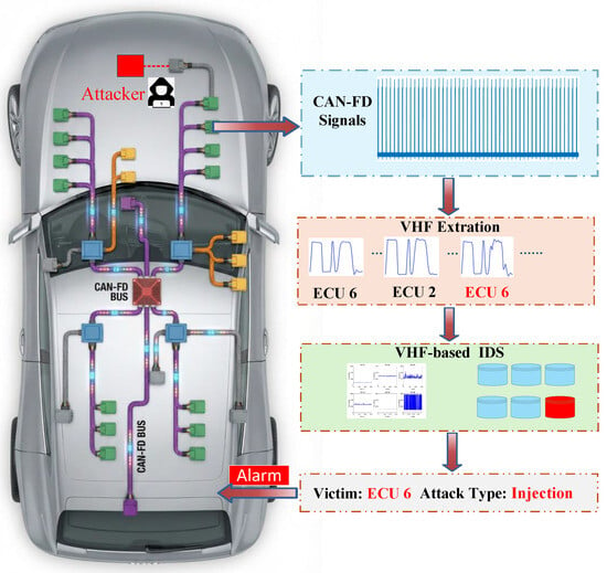
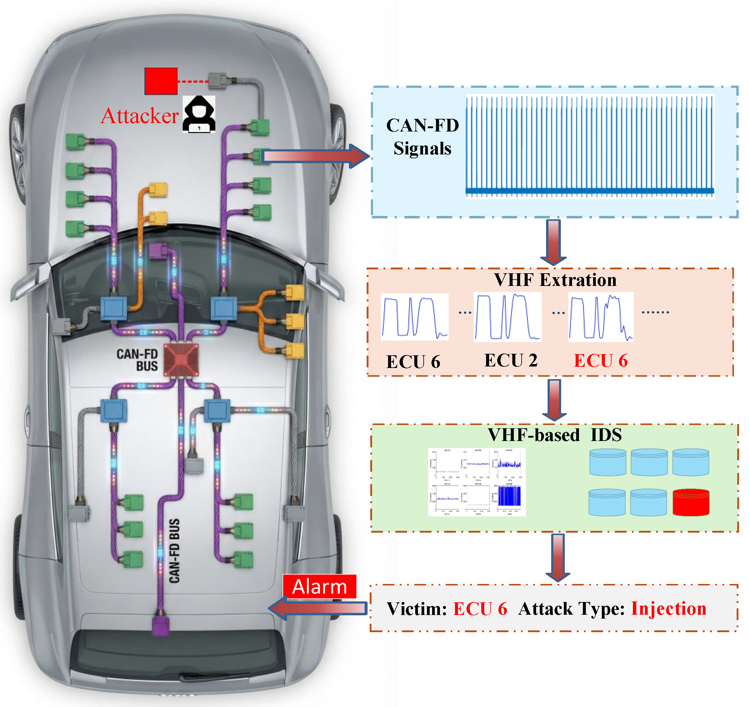
Motivated by these considerations, our approach uses the “physical first impression” (voltage characteristics) of ECUs to enable rapid, low-overhead authentication for resource-constrained edge devices. Building on this lightweight, physical-layer authentication paradigm, this paper shifts its focus to the development of a CAN-FD-based VIDS implementation framework. A key innovation lies in extending this paradigm to enable the joint identification and traceability of both ECU individual counterfeiting and malicious attack scenarios. Figure 1 illustrates the overall architecture of the VIDS scheme designed in this paper. The main contributions of this paper are reflected in the following three aspects:
Figure 1.
The Proposed CAN-FD VIDS Scheme Illustration.
- This paper proposes a CAN-FD ECU fingerprinting method based on VHFs. Through integrating the fixed control field and inherent edge features of the CAN-FD data field via segmented integration and edge filtering, robust and distinguishable hardware fingerprint features are generated. Against typical substitution and masquerade attacks, the proposed scheme achieves a high identification accuracy of 99.6%.
- We analyze the VHF offset characteristics in typical spoof attacks and eavesdropping attacks and propose a lightweight VIDS scheme to identify attack scenarios and trace the source of the attacked ECU. Our solution delivers a single-frame recognition latency of approximately 2 ms and an attack scenario recognition latency of 500 ms, while attaining 100% accuracy in identifying attack types. Therefore, our system can significantly enhance the security of the CAN-FD bus.
- We also explored key factors impacting VHF offset under real-vehicle operating conditions, including temperature and bus data-load rate. These factors were verified to potentially induce detection model failure, prompting the proposal of feasible solutions.
2. Related Work
Given that this paper focuses on leveraging hardware characteristics to identify malicious ECUs, we selected representative VIDS technologies for comparative analysis and as an overview. As illustrated in Table 1, this comparison delineates the key distinctions between existing approaches and the method proposed herein.
Table 1.
Comparison of the VIDS Approaches.
As a critical branch of vehicle CAN network security protection, VIDS centers its research on two core directions: voltage feature extraction and detection model optimization. Through iterative innovation, related studies have formed a progressive technical landscape while exposing practical limitations. Early explorations laid the foundation for VIDS application. In 2014, Murvay [27] pioneered the use of voltage characteristics in the CAN bus arbitration segment for device identification, verifying the distinguishability of features via methods like Mean Squared Error (MSE), convolution, and multi-frame averaging (noting that multi-frame superposition required over 1000 frames to take effect). Their tests—conducted on 10 same-model USB-CAN adapters and 5 embedded development boards (including dual transceivers)—demonstrated favorable distinguishability, yet failed to cover 500 Kbps critical ECU devices. Additionally, arbitration domain conflicts easily led to the mixing of multiple device fingerprints, which were hard to separate.
Subsequent studies focused on enhancing feature richness and model adaptability. Avatefipour et al. [28,29,30] leveraged the LibXtract library and FEAST toolbox to extract 11 time-frequency domain features from the CAN signal ID segment, then combined an Artificial Neural Network (ANN) model to achieve 95.2% accuracy in distinguishing cable types and lengths. However, their experiment relied on fixed messages and overlooked the interference caused by temperature variations. Cho and Shin [35] proposed the Viden method, which adopted Recursive Least Squares (RLS) adaptive signal processing to realize online fingerprint updates—supporting low sampling rates (50 Ksps) and all message type/rate scenarios. By integrating real-time Vcc (supply voltage) tracking to eliminate voltage and temperature interference, their tests on prototype equipment and real vehicles (i.e., 2013 Honda Accord, 2014 Chevrolet Trax) reduced the misrecognition rate to as low as 0.2%.
Emerging research focuses on fusing multiple HFBM feature categories to boost identification performance under specific attack scenarios. Popa et al. proposed a physical fingerprinting method for ECUs on CAN buses, conducting experiments on 10 vehicles (9 passenger cars and 1 SAE J1939-compliant heavy-duty vehicle) involving 54 ECUs [36]. They collected over 8 million frames for clock skew calculation and 229,510 bits for voltage feature extraction (mean voltage, max voltage, bit time, plateau time). However, the method relied on high-end hardware (e.g., PicoScope 5000 (Pico Technology, St Neots, UK)) for voltage collection, ignored long-term environmental impacts and couldn’t support real-time intrusion detection. Pierpaolo et al. propose an embedded real-time intrusion detection algorithm based on VHF [20]. This algorithm enhances the KNN model by storing only the CANH/CANL voltage average of each ECU as a unique fingerprint. Deployed on the AURIX TC375 (Infineon Technologies, Neubiberg, Germany) platform, the algorithm was tested on an 8-node prototype constructed using real-vehicle data from the Alfa Romeo Giulietta. However, the algorithm has notable limitations: it does not cover common attacks like spoofing. Furthermore, its short experimental duration (merely 1 min) means long-term operational stability and performance after ECU aging have not been validated.
Despite these preliminary attempts to exploit physical-layer fingerprints for ECU identification and intrusion detection, all the aforementioned methods still suffer from inherent drawbacks that severely limit their real-world applicability in modern automotive systems. A critical limitation of existing baselines is their reliance on multi-frame accumulation [20,27,35,36]. For example, traditional VIDS requires aggregating over 1000 frames to achieve distinguishable features, while the method in [36] requires over 8 million frames for reliable clock calculation. Quantitatively, in a typical in-vehicle network, waiting for thousands of periodic frames introduces a detection latency of several seconds to minutes, which is unacceptable for preventing real-time malicious control.
Furthermore, these legacy methods were designed for low-speed CAN and cannot be directly migrated to high-speed CAN-FD testbeds, as they lack the capability to process dual-rate switching and ultra-fast transient edges. In contrast, our proposed method leverages lightweight segmented integration to achieve highly accurate detection using only a single CAN-FD frame, demonstrating superior computational efficiency and adaptability for resource-constrained ECUs.
3. Background
3.1. Protocal
CAN-FD is an enhanced version of the classical CAN protocol, which significantly improves data transmission rates and communication efficiency while maintaining backward compatibility [37,38]. This protocol employs a dual-phase variable data rate mechanism: the control field up to the BRS maintains the same transmission speed as classical CAN (up to 1 Mbps), ensuring compatibility with existing CAN networks; meanwhile the segment from the BRS bit in the control field to the acknowledgment (ACK) field can achieve transmission rates of up to 8 Mbps, with specific performance dependent on network topology and hardware implementation. Furthermore, CAN-FD substantially expands the maximum data payload per frame from 8 bytes in classical CAN to up to 64 bytes, thereby enabling efficient transmission of high-volume data.
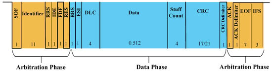
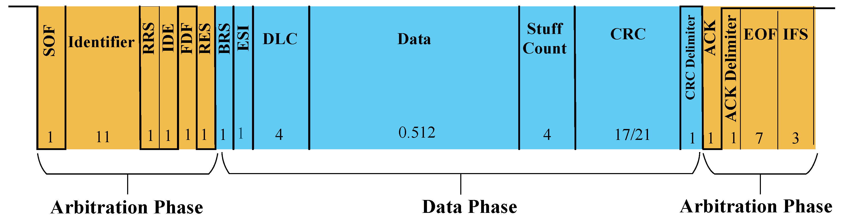
As shown in Figure 2, the overall structure of the CAN-FD frame follows the basic framework of the classic CAN frame, but to support higher data rates and larger payloads, significant expansions have been made in the control field and the data field. The control field is the key expansion area of CAN-FD, which extends the classic CAN format by introducing additional control bits, including FDF bits, BRS bits, and error status indicator (ESI) bits. Among them, the FDF bit is used to distinguish CAN-FD frames from classic CAN frames; the BRS bit is used to switch to a higher bit rate during the data phase; and the ESI bit indicates the error status of the sending node.
Figure 2.
The CAN FD Frame Structure.
CAN-FD employs an improved CRC calculation method to accommodate larger payload sizes and higher data rates. The CRC in CAN-FD is an error detection mechanism used to ensure the integrity of data transmission. This protocol uses a 17-bit CRC for frames with a data length of no more than 16 bytes, and a 21-bit CRC for longer frames, providing enhanced error detection capabilities. Additionally, a fill counter mechanism is implemented to improve the robustness of the fill rules, ensuring reliable data transmission even under adverse conditions. The error limitation mechanism is similar to the classic CAN, monitoring the health of nodes through sending and receiving error counters, and isolating faulty nodes through bus shutdown status when the error threshold is exceeded.
3.2. Threat Model
Given that the attacker has already breached the access control and obtained full access rights to the CAN-FD bus, this study focuses on defense technologies based on voltage feature recognition, aiming to precisely address potential spoofing attacks in the bus environment. Regarding advanced spoofing threats, an attacker cannot bypass the system by subtly modulating ECU voltage characteristics. Conventional vehicle attacks exploit software or firmware vulnerabilities, whereas our VHFs are rooted in intrinsic analog electrical properties (e.g., impedance mismatches and transceiver capacitance) hard-coded in the physical circuit. Attackers cannot modify software timers or registers to fake analog voltage levels or transient edges, guaranteeing inherent robustness against software-driven spoofing.
Through a systematic review of the attack scenarios on the CAN-FD bus and analysis of the behavioral characteristics, this paper classifies the current typical attack threat behaviors into the following four core methods.
3.2.1. Substitution Attack
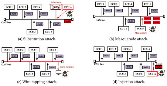
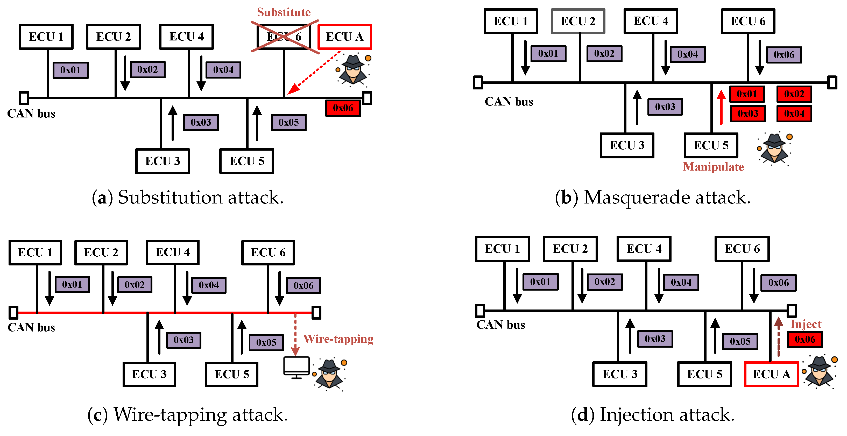
The schematic diagram of the substitution attack is shown in Figure 3a. In this attack scenario, the malicious ECU A will disguise itself as the victim ECU 6, and by sending the message identifiers that originally belonged to ECU 6, it will carry out a spoofing attack. This type of attack poses a critical threat in that the illegitimate ECU can be fully replaced and mimicked at the identical physical location of the legitimate one, rendering conventional IDS approaches utterly ineffective in detecting the presence of malicious intrusions.
Figure 3.
CAN-FD Attack Scenarios.
3.2.2. Masquerade Attack
The schematic diagram of the intra-domain spoofing attack is shown in Figure 3b. In this attack mode, the attacker controls the legitimate ECU 5 either remotely or locally, and then operates it to send counterfeit messages. This attack method is highly deceptive because from the perspective of network topology and it is difficult for other devices to distinguish that the communication object has changed. The attacker can remain hidden for a long time and control the behavior of the entire network [8].
3.2.3. Wire-Tapping Attack
The schematic diagram of the wire tap eavesdropping attack is shown in Figure 3c. In this attack mode, the attacker uses a probe to utilize the twisted pair of the CAN-FD network as the invasion path to achieve unauthorized access to the CAN-FD bus network. The attacker adopts a passive listening strategy and can obtain all the communication data between legal nodes in the network. Compared with the active injection attack, this attack method does not generate additional messages, maintaining the integrity of the original network architecture and making defense measures such as PIDS and CIDS ineffective.
While the wire-tapping attack is completely passive, physically attaching the probe to the CAN-FD twisted pair inevitably introduces additional parallel capacitance and disturbs the global electrical impedance of the network. This impedance perturbation subtly distorts the analog waveforms of periodic messages transmitted by legitimate ECUs, including steady-state voltages and transient edge characteristics.
3.2.4. Injection Attack
The schematic diagram of the injection attack is shown in Figure 3d. The malicious ECU A uses an intrusion to access the CAN-FD network. While maintaining the integrity of the original network architecture, an additional twisted-pair wire is physically connected to the network bus. Once successfully connected, ECU A begins to send forged CAN-FD frames, which carry the message identifier of the legitimate ECU 6. This attack method is highly covert because the original network topology is not disrupted, and other devices may not immediately detect the presence of an additional malicious node in the network. The attacker can choose to send forged frames at specific times to interfere with the normal communication process or inject malicious control instructions.
4. VHF Extraction and Attack Traceability Mechanism
4.1. Data Acquisition and Verification
The preprocessing process begins with frame synchronization upon receiving CAN-FD frames. The frame synchronization algorithm uses a cyclic traversal method to analyze the received signal. Specifically, the system counts the sampling points of the low level (corresponding to recessive bits). When the cumulative count exceeds the total number of sampling points allocated for the end of frame (EoF) and inter-frame space (IFS) segments, the algorithm evaluates the voltage level at the current sampling point. If a high level (dominant bit) is detected at the current sampling point, this position is designated as the start of frame (SoF) position. Otherwise, if these conditions are not met, the SoF synchronization process is determined to have failed.
4.2. Voltage Characteristic of the Control Field
After successfully completing frame synchronization, a complete CAN-FD message is obtained. The system then uses differential synchronization technology to extract the control field, including reserved bit (RES), BRS, ESI, and data length code (DLC) segments from the control field. To elaborate, the process of extracting VHFs for the control field consists of the following key steps:
Initially, CAN-FD message signals transmitted by all ECU nodes are acquired at a sampling rate of , with each legitimate device separately capturing M message groups.
Subsequently, specific control fields are extracted from the CAN-FD message frames. As the DLC enables data frames with variable lengths ranging from 8 to 64 bytes, this study designates the RES, BRS, and ESI bits within CAN-FD as the Regions of Interest (RoIs).
To meet the real-time requirement and strengthen the anti-interference capability of fingerprints, the VHFs corresponding to the control segment signal is further derived via piecewise integration, with the specific process shown below.
where I is the integral interval and L denotes the number of integration segments.
This piecewise integration process serves a dual purpose. First, it acts as a robust low-pass filter, mitigating high-frequency noise and enhancing the stability of the VHFs. Second, and more importantly, it functions as a critical dimensionality reduction technique. Given the extremely high sampling rate of 125 MHz, processing the raw data points directly would yield a massive feature vector, incurring prohibitive computational overhead for the subsequent covariance matrix and Mahalanobis distance calculations. By aggregating the abundant raw points into L discrete segments based on the integral interval I, the dimension of the extracted feature vector is drastically reduced.
Although traditional statistical methods such as PCA were considered, they incur a high computational cost (e.g., eigenvalue decomposition) and map data into a non-physical orthogonal space, losing the temporal electrical interpretability of CAN signals. By grouping raw waveform points into L discrete segments via integral interval I, our method achieves substantial dimensionality reduction while preserving waveform physics.
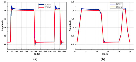
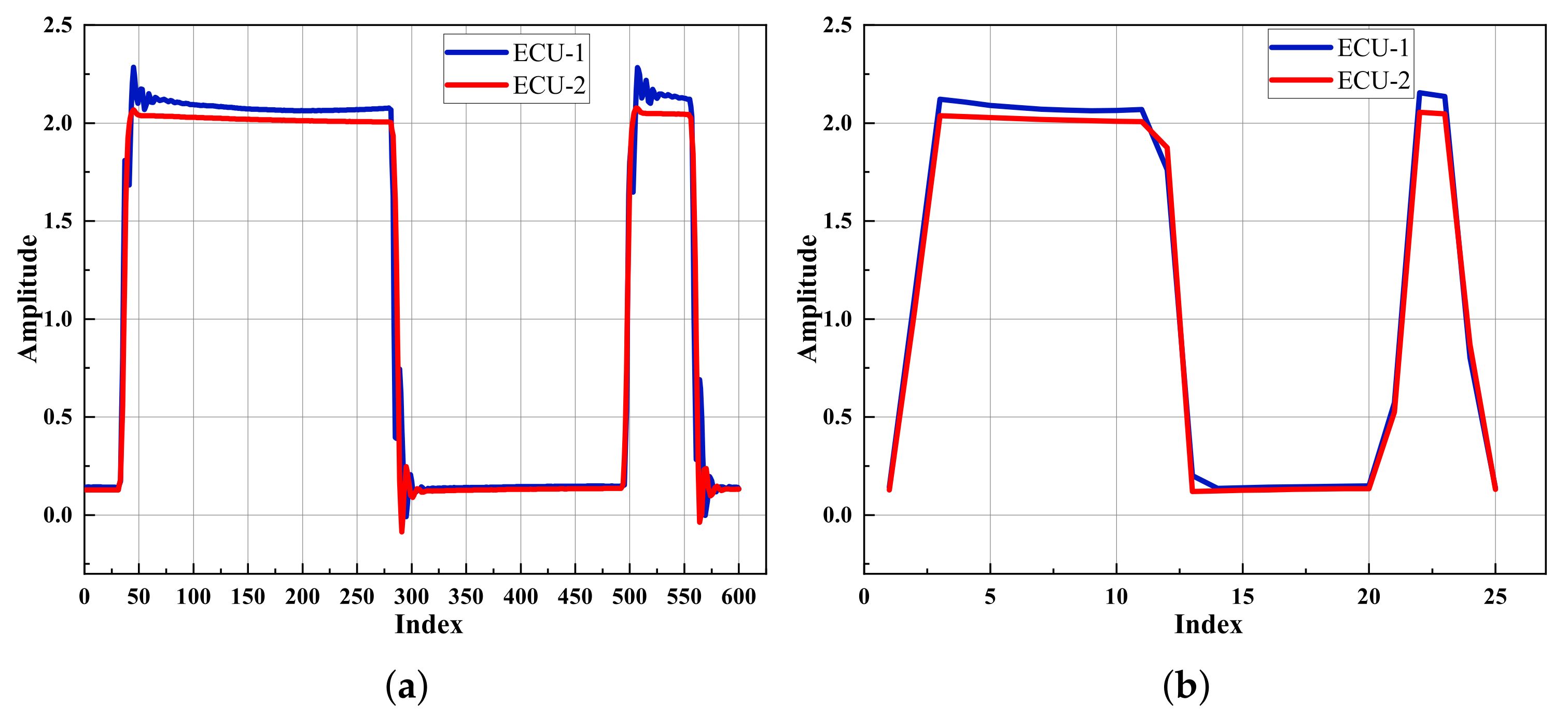
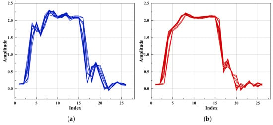
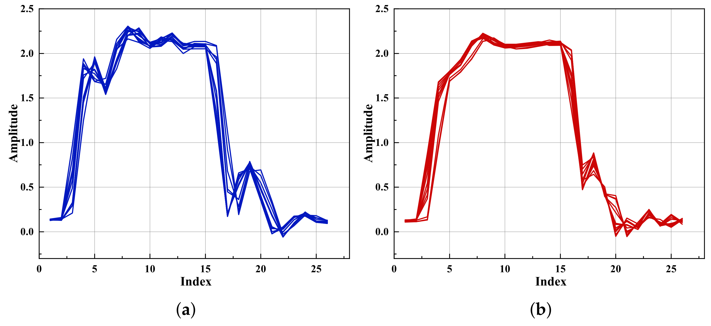
Figure 4a shows the differential signal extracted from ECU 1 and ECU 2. As observed from the waveform, variations exist among different devices in terms of the rising edge, steady-state voltage, and falling edge of these fields. These differential characteristics can be utilized for device authentication. Furthermore, as illustrated in Figure 4b, piecewise integration operations effectively accumulate voltage characteristics, thereby enhancing the stability of VHFs.
Figure 4.
Voltage Features Extracted Using Different Devices: (a) Voltage Signals for the Arbitration; (b) The Extracted VHFs.
4.3. Edges of the Data Field
After extracting the data field, the starting point is determined point by point based on edge threshold parameters, with results recorded simultaneously. Three key parameters are referenced for the determination: the differential value, the voltage value of the starting point, and the voltage values of after .
Specifically, for determining the starting point of rising edge, the judgment conditions are as follows:
where , , are voltage thresholds at different conditions.
Similarly, the judgment conditions for of falling edge are as follows:
where , , are voltage thresholds under different conditions.
At high sampling rates for CAN-FD signals, random sampling jitter and minor deviations in sampling points can lead to instability in the raw signals and errors in identifying the start positions of rising and falling edges. To reduce the influence of sampling jitter on edge extraction accuracy, rising and falling edges are not evaluated individually. Instead, they are extracted from the data-domain signal to form corresponding sets, and the final rising-edge fingerprint and falling-edge fingerprint are obtained via superposition and averaging. This multi-edge averaging scheme effectively suppresses random jitter and ensures the stability of edge features.
As shown in Figure 5, the stitched edge fingerprints extracted from different devices exhibit obvious inter-device variability. After averaging and concatenation, the resulting VHFs = { } demonstrate robust stability and prominent discriminative ability across devices.
Figure 5.
Edge Fingerprint. Depicts the Rising and Falling Edge Curves of the Combination Extracted from ECU 1 (a) and ECU 2 (b).
4.4. Proposed VHF-Based CAN-FD IDS
VHF matching calculates the distance between the extracted device VHF and pre-stored ones in the database. It then uses a set threshold to determine if the current VHF is normal, providing a basis for subsequent attack traceability.
During the training phase, we pre-collect R messages from device i and extract the corresponding mean VHF as follows:
where is composed of , and . On this basis, we proceed to calculate the covariance matrix of each device fingerprint, with the specific method as follows:
We then employ Mahalanobis distance for similarity matching, specifically to realize a lightweight fingerprint authentication process.
To get the distance threshold, we further collect group messages as verification set, extract VHF , and calculate its Mahalanobis distance from the training VHFs. The specific calculation process is as follows:
Then we used the sigma rules in statistical analysis to determine the range of distances for normal VHFs [39]. The boundary value of normal VHF distribution is calculated as follows:
where and are the mean and standard deviation of respectively.
To unify authentication decision thresholds across heterogeneous devices, we propose a normalized threshold approach. Specifically, we define a metric termed the VHF deviation degree (V), formulated as
During the testing phase, we further determine whether the j-th reveived frame is legal or illegal on the basis of . The calculation process is expressed as
Nevertheless, mere detection of illegal recognition proves inadequate for identifying the underlying attack mechanism in various scenarios. Since attacks like wiretap or injection can distort the VHF of legitimate ECUs—leading to potential false positives—a more robust approach is required. Therefore, we introduce a granular attack traceability framework to analyze the attack model, identify compromised devices, and enable precise judgment of the intended target.
In practical systems, we accumulate S signal frames from all N ECUs in the network (via continuous collection over a period), count the number of illegally identified frames (denoted as ), and calculate the mean and standard deviation of their deviations. When the illegal frame occupation rate reaches a certain ratio, i.e., , the VHF-based IDS mode will be activated.
The detection process is demonstrated in Algorithm 1. To guarantee the reproducibility of the attack traceability mechanism, the specific definitions of systemic parameters and the operational schedule are explicitly detailed below:
- : The legality boundary threshold. An “illegal packet” is strictly defined as any single frame whose instantaneous distance deviation satisfies .
- : The sliding window size. To avoid false alarms caused by transient physical noise, the system buffers the most recent S frames across all N ECUs.
- & : denotes the illegal frame rate within the current window. If (the triggering threshold), it indicates a persistent anomaly, thereby activating the traceability algorithm.
- & : is used to evaluate if the anomaly is global or local. evaluates the maximum standard deviation () to distinguish between a passive wire-tapping attack and an active injection attack.
| Algorithm 1 The VHF-based Detection Process |
|
Regarding the update schedule, as new CAN-FD frames continuously arrive, the sliding window of size S shifts dynamically. The statistical parameters (illegal frame count , mean deviation , and standard deviation ) are continuously updated over this S-frame window. When the condition is met, Algorithm 1 leverages these updated parameters to execute the decision tree, ultimately outputting the specific attack model and isolating the target ID.
5. Experimental Setup
5.1. Network Architecture
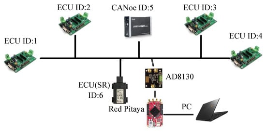
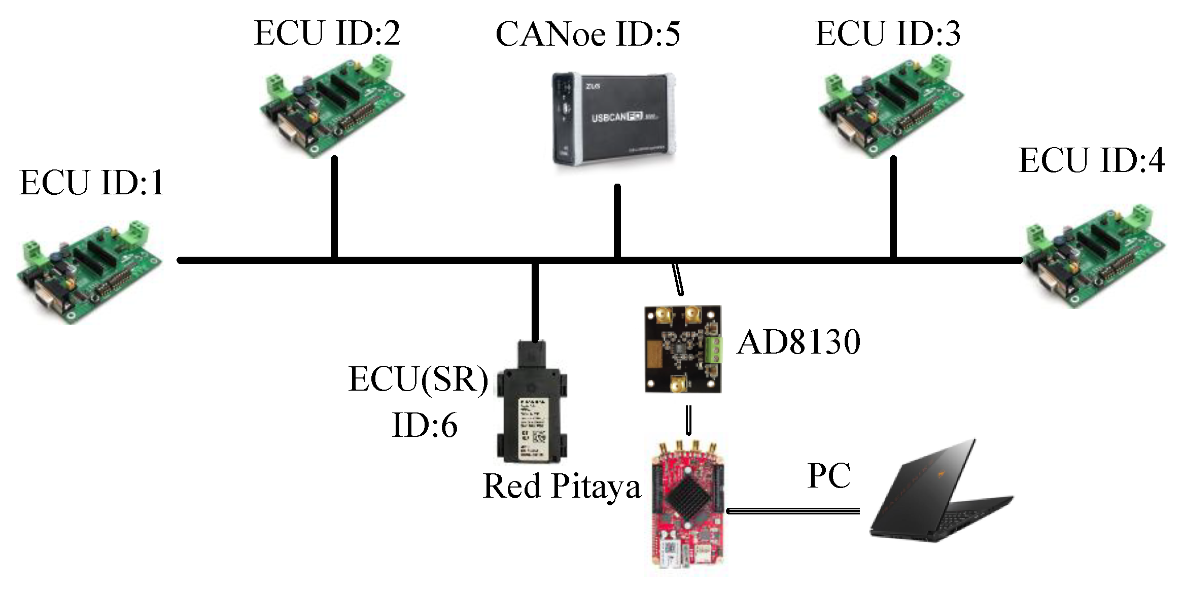
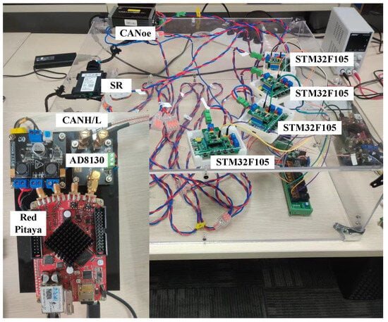
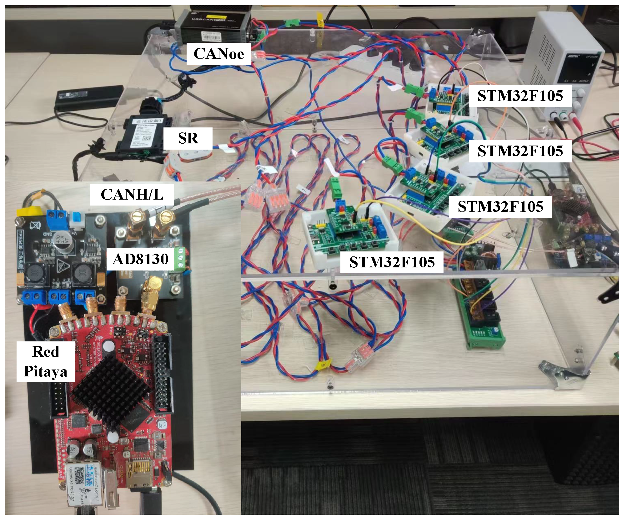
For experimental validation, a uniquely designed 6-node bus-type CAN-FD network is depicted in Figure 6. The network comprises four STM32F105 development boards, one CANoe tool, and one short-range radar (SR) module.
Figure 6.
Schematic Diagram of Components and Device Connections in the Experimental Setup.
During the acquisition of CANH/CANL signals, a signal deviation was observed. This discrepancy is attributed to the asynchronous clocks of the dual-channel acquisition system under edge-triggered conditions, which introduces timing errors into the captured CAN-FD frames. To mitigate this, an AD8130 (Analog Devices, Wilmington, MA, USA) differential amplifier was integrated into the experimental setup. Specifically, the AD8130 functions as a differential front-end that reconstructs the waveform by subtracting CANL from CANH, thereby effectively suppressing common-mode interference and isolating the high-fidelity differential CAN signal. This board calculates the differential signal to reconstruct the authentic message waveform, which is subsequently acquired by the Red Pitaya for follow-up analysis. Our Experimental Prototype is shown in Figure 7.
Figure 7.
Our Experimental Prototype.
To strictly meet the real-time processing requirements of the in-vehicle intrusion detection system, the computational architecture is highly optimized for edge devices. Both the 125 MHz high-frequency signal sampling and the subsequent operations—including signal preprocessing, piecewise integration, and VHF feature extraction—are executed directly on the Red Pitaya embedded board utilizing its native C/C++ API. The host PC does not participate in the real-time computational pipeline; rather, it is exclusively utilized to provide a graphical user interface (GUI) for the visualization of authentication results. This edge-computing software architecture ensures that the system’s detection latency is unaffected by PC-based processing overheads.
The CAN-FD differential signal is collected at a sampling rate of 125 MHz. This high sampling rate is explicitly linked to the frame’s bit lengths across different transmission phases to ensure sufficient data granularity. Specifically, during the arbitration phase (running at 500 kbit/s), the duration of a single bit is 2 , yielding exactly 250 data points per bit (e.g., 2750 points for the 11-bit Identifier). During the high-speed data phase (running at 2 Mbit/s), the duration of a single bit is 0.5 , resulting in 62.5 data points per bit (e.g., 250 points for the 4-bit DLC). This dense sampling guarantees that both steady-state voltages and microscopic edge transitions are captured with high precision.
5.2. Attack Scenarios
Based on the threat models presented in Section 3, we constructed four attack scenarios to validate the effectiveness of the proposed VHF detection scheme. In the substitution (abbreviated as sub.) attack, an attacker replaces ECU 6 with a counterfeit ECU A (the same SR model), which forges the message data originally transmitted by ECU 6. In the masquerade (abbreviated as mas.) attack, the attacker is assumed to remotely hijack CANoe and send fake messages to impersonate ECU 1/2/3/4, aiming to disrupt the normal operation of the CAN-FD network. In the wire-tapping (abbreviated as wir.) attack, the attacker connects to the CAN-FD network via a probe to receive message data from all devices on the network, thereby achieving the goal of sniffing. In the injection (abbreviated as inj.) attack, the attacker infiltrates the CAN-FD network, connect the new ECU A to the bus, and manipulates it to forge the message data that ECU 6 would normally transmit. The devices involved in each specific scenario are detailed in Table 2.
Table 2.
Attack Scenarios and the ECU Involved.
Specifically, in our experimental setup, the wire-tapping attack was implemented using a same-model STM32 ECU (STMicroelectronics, Geneva, Switzerland) configured in “listen-only” mode, possessing a standard transceiver input impedance of approximately 32 kΩ.
5.3. Metrics
Given that the ID information of the current CAN-FD message can be parsed, our identification scheme falls under the category of authentication-based identification. Specifically, it performs a 1 vs. 1 device comparison and outputs a verdict on whether the current message is legitimate. Consequently, in the verification environment, we select effective binary classification evaluation metrics.
- True Positive () refers to the scenario where the ECU is legitimate and the model’s prediction result is also legitimate, indicating correct identification of legitimate devices.
- True Negative () denotes the case where the ECU sends an illegal message and the model correctly predicts that the message originates from an illegal device, representing accurate detection of illegal messages.
- False Positive () describes the scenario where an illegal ECU sends a counterfeit message but the model mistakenly predicts it as legitimate, meaning missed detection of illegal devices.
- False Negative () corresponds to the situation where the ECU sends a legitimate message but the model incorrectly classifies it as illegal, which is a false alarm for legitimate traffic.
Based on these, we provide the following definition of the metrics. Precision reflects the reliability of the model’s predictions for positive-class outcomes, and its calculation formula is as follows:
Recall denotes the proportion of actual intrusion attack samples that are correctly predicted as such, reflecting the model’s ability to identify positive-class samples.
The F1-score is the harmonic mean of precision and recall, offering a balanced assessment of the two metrics.
Accuracy represents the proportion of correct predictions among all predictions and is the most intuitive overall performance metric.
6. Experimental Results
6.1. Comparative Performance of Various VHFs
To explore the optimal performance among various VHF schemes, this study conducts a systematic evaluation of five distinct VHF schemes tailored for attack traceability in CAN-FD networks. A comprehensive VHF feature library is constructed, encompassing: VHF 1 (rising edge, ), VHF 2 (falling edge, ), VHF 3 (concatenated edge, {), VHF 4 (piecewise integration of the voltage feature, ), and VHF 5 (fusion of voltage feature and edge, ).
The efficacy and robustness of these five schemes were rigorously tested under two distinct attack scenarios (substitution attack and masquerade attack), as detailed in Table 3 and Table 4. For each ECU, a total of 800 message frames were collected for fingerprint extraction, yielding a total dataset size of 4800 CAN-FD frames across the 6-node network. This dataset was partitioned into a training set and a validation set, each comprising 400 frames. This experimental setup allows us to assess the performance of the different schemes in detecting and attributing the source of sophisticated CAN bus attacks.
Table 3.
Performance of Multiple Types of VHFs Under Substitution Attacks.
Table 4.
Performance of Multiple Types of VHFs Under Masquerade Attacks.
The experimental results reveal a clear and consistent performance hierarchy across both attack scenarios. In the substitution attack scenario (Table 3), VHF 5 consistently achieved the highest performance, with an accuracy of 99.6% and an F1-score of 99.2%, significantly outperforming all other schemes. VHF 4, however, showed the weakest performance, with an accuracy of 88.0% and an F1-score of 88.6%. Similarly, VHF 2 performed poorly in the substitution attack, with an accuracy of 89.5% and an F1-score of 89.7%.
This trend was also observed in the more challenging masquerade attack scenario (Table 4), where VHF 5 again ranked first across all four victim ECUs, with accuracies ranging from 99.1% to 99.6% and F1-scores between 99.1% and 99.3%. In contrast, VHF 4 and VHF 2 remained the least effective solutions, with accuracy values ranging from 91.6% to 93.3% for VHF 4 and 90.0% to 92.9% for VHF 2, and F1-scores from 90.9% to 93.6% for VHF 4 and 90.5% to 93.3% for VHF 2. This quantitative comparison validates our feature fusion strategy. By fusing complementary physical characteristics, our combined feature set achieves an F1-score above 99.1%, demonstrating that the fusion of control-segment voltage profiles and data-field transient edges is essential for high-precision CAN-FD intrusion detection.
A significant finding from both attack scenarios is the improvement in performance achieved by fusing data field features, as demonstrated by VHF 3. This hybrid feature set consistently outperformed individual edge features (VHF 1 and VHF 2), emphasizing the importance of integrating data field features for better individual recognition. Moreover, while VHF 4, which uses only control field features, was insufficient for accurate attack traceability on its own, its integration into VHF 5 (a combination of VHF 3 and VHF 4) led to a substantial performance boost. This suggests that control field features, although not as discriminative alone, provide valuable complementary information that significantly enhances the robustness of the system against complex attack scenarios.
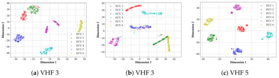
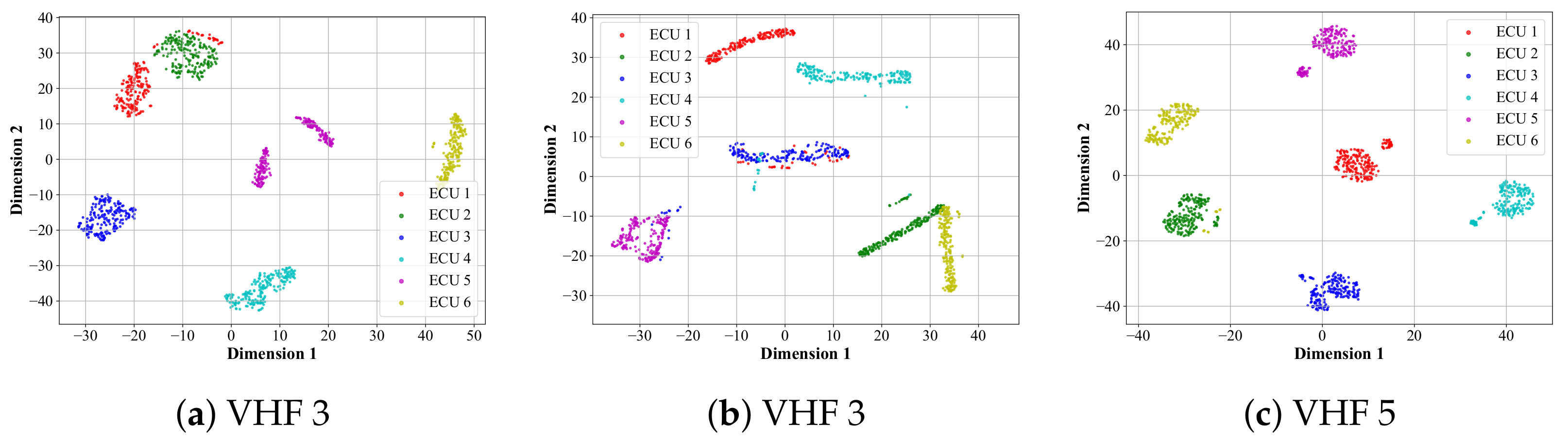
The t-SNE visualization of the VHFs under a normal operation scenario is also shown in Figure 8. The t-SNE plots provide insights into how well the VHFs differentiate the ECUs under normal circumstances. VHF 5 demonstrates the best feature separation (Figure 8c), where the points for each ECU are well-clustered and separated from one another. VHF 3 (in Figure 8a) also shows a clear separation, though the clusters are more spread out compared to VHF 5, indicating it is slightly less effective. In contrast, VHF 4 (Figure 8b) shows the least-distinct separation, with some overlap between different ECUs, reflecting the limitations of control field features in distinguishing between ECUs under a normal operation scenario.
Figure 8.
t-SNE Visualization on Different VHFs Under No-Attack Scenarios. The Same-Color Samples Belong to One ECU.
In conclusion, the experimental results demonstrate that VHF 5, which integrates both data field and control field features, provides the most robust solution for accurate authorization, making it well suited for attack detection in CAN FD systems. Notably, using four identical STM32F105 boards represents a rigorous test for physical fingerprinting. Distinguishing identical batch devices (intra-model variation) depends solely on microscopic manufacturing variations—which is far more challenging than differentiating ECUs from different manufacturers (inter-model variation) with distinct circuit designs. Successful classification of these identical nodes demonstrates the system’s capability to handle the higher signal diversity in multi-vendor real-vehicle environments.
6.2. Performance of VIDS
6.2.1. Analysis of Attack Scenarios
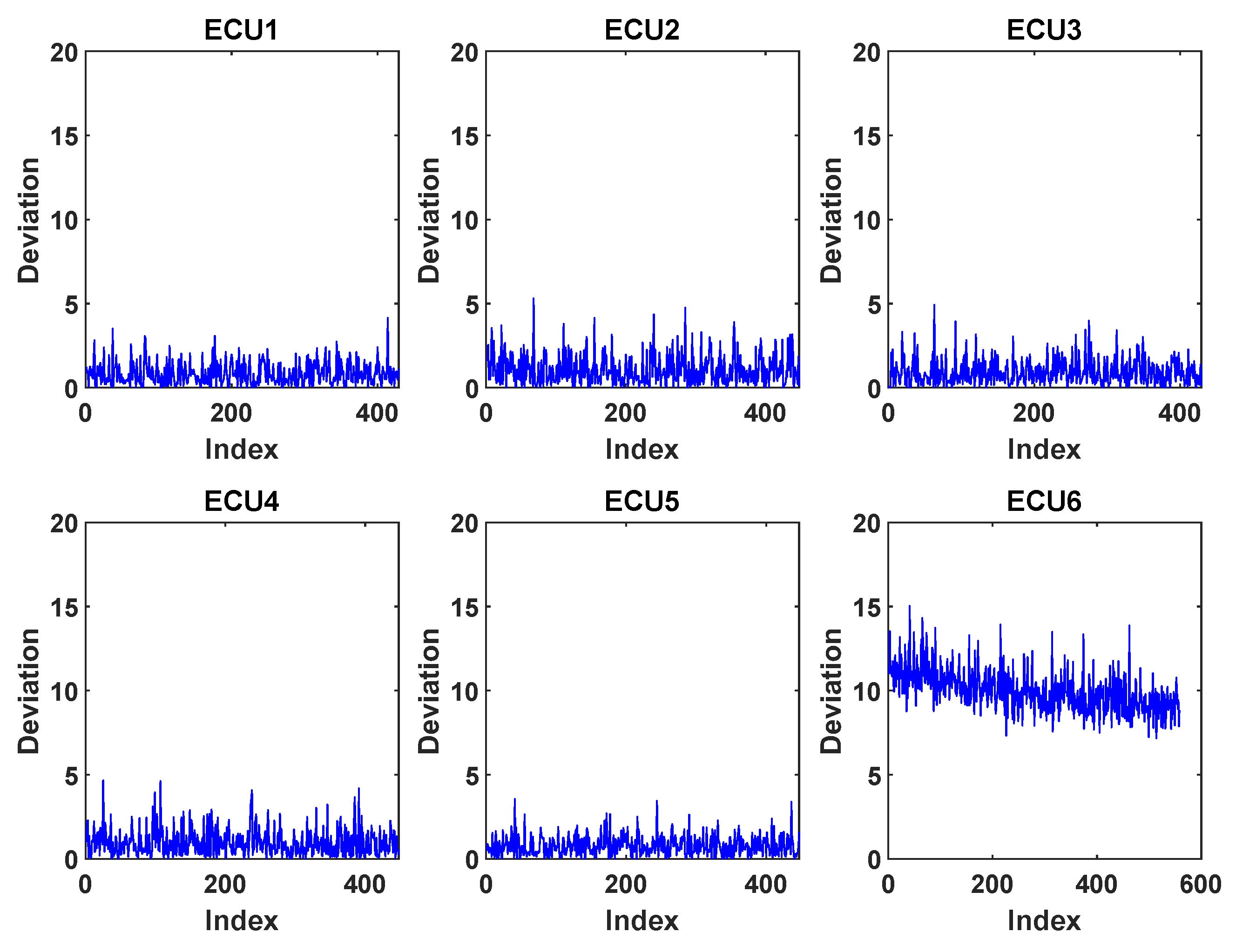
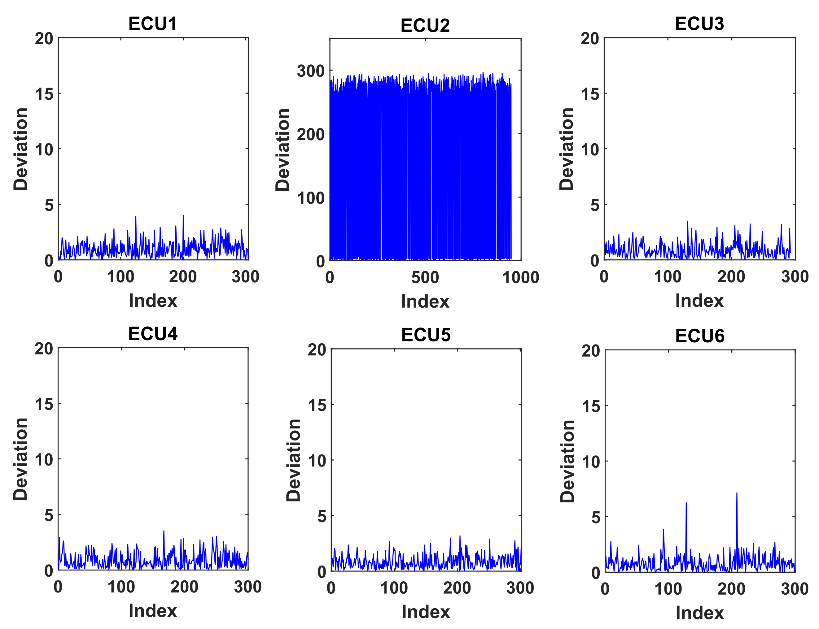
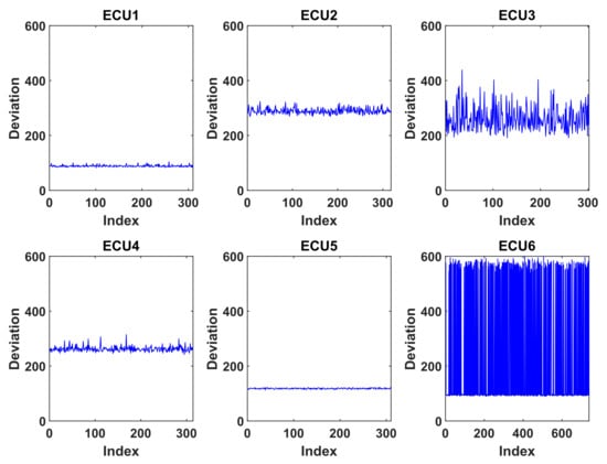
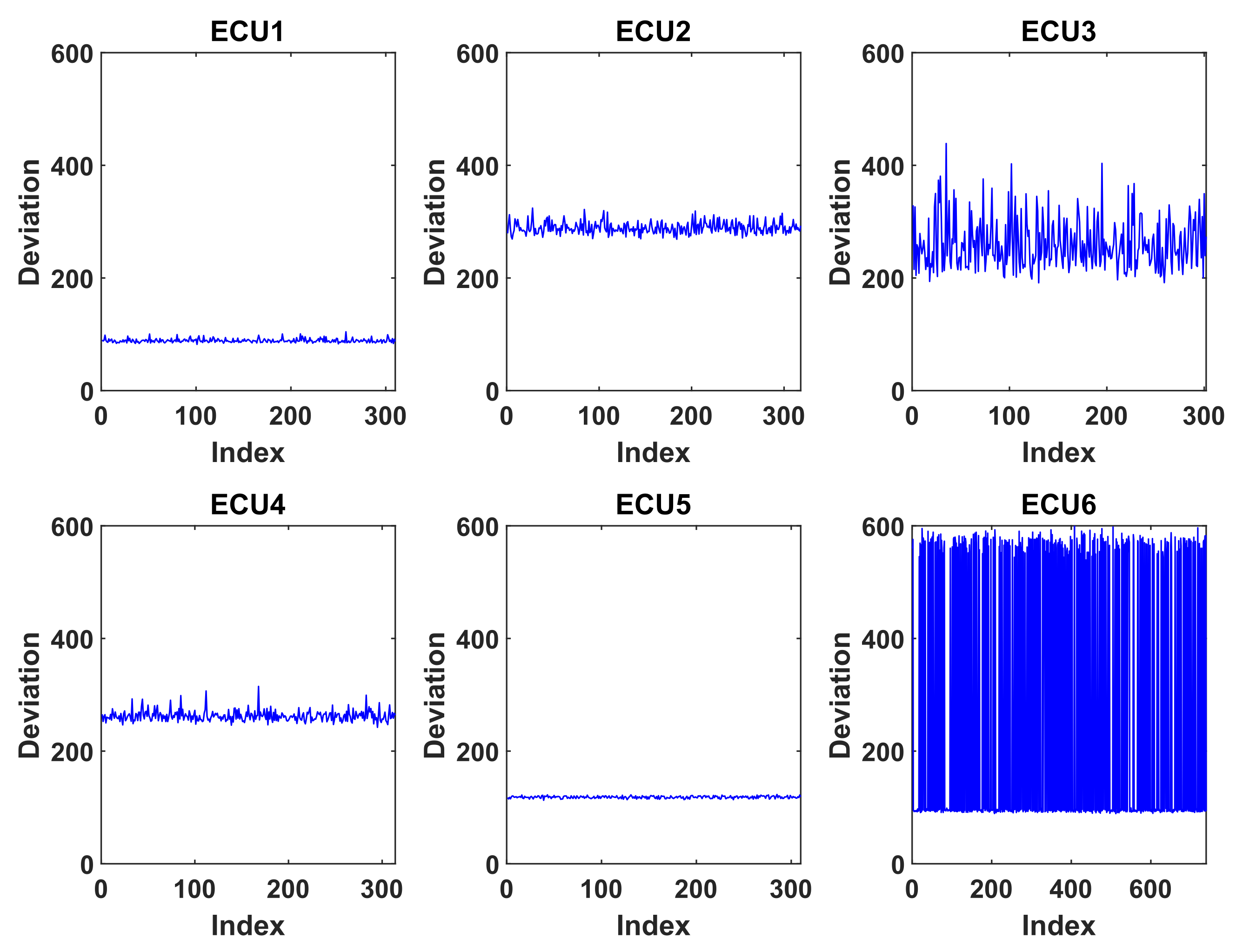
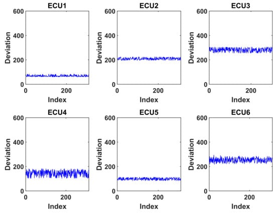
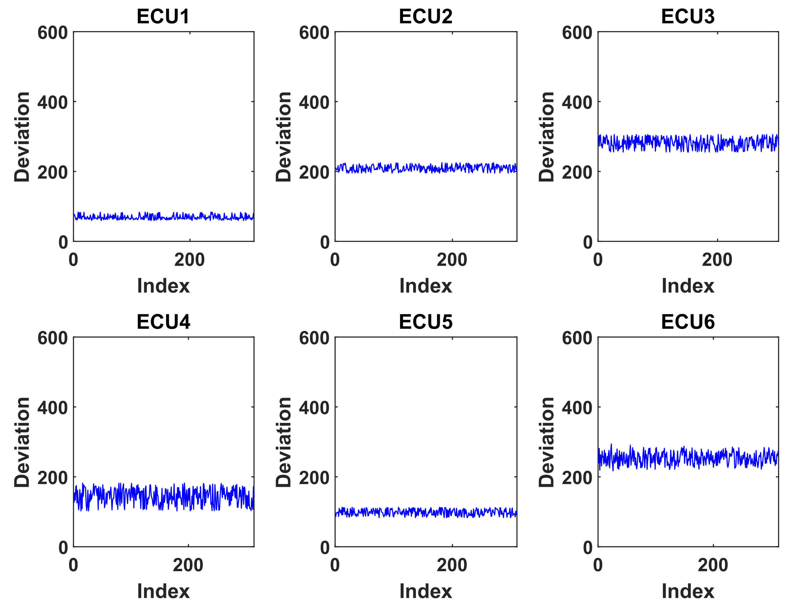
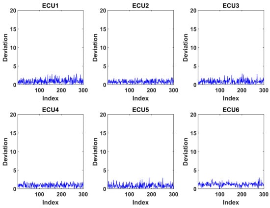
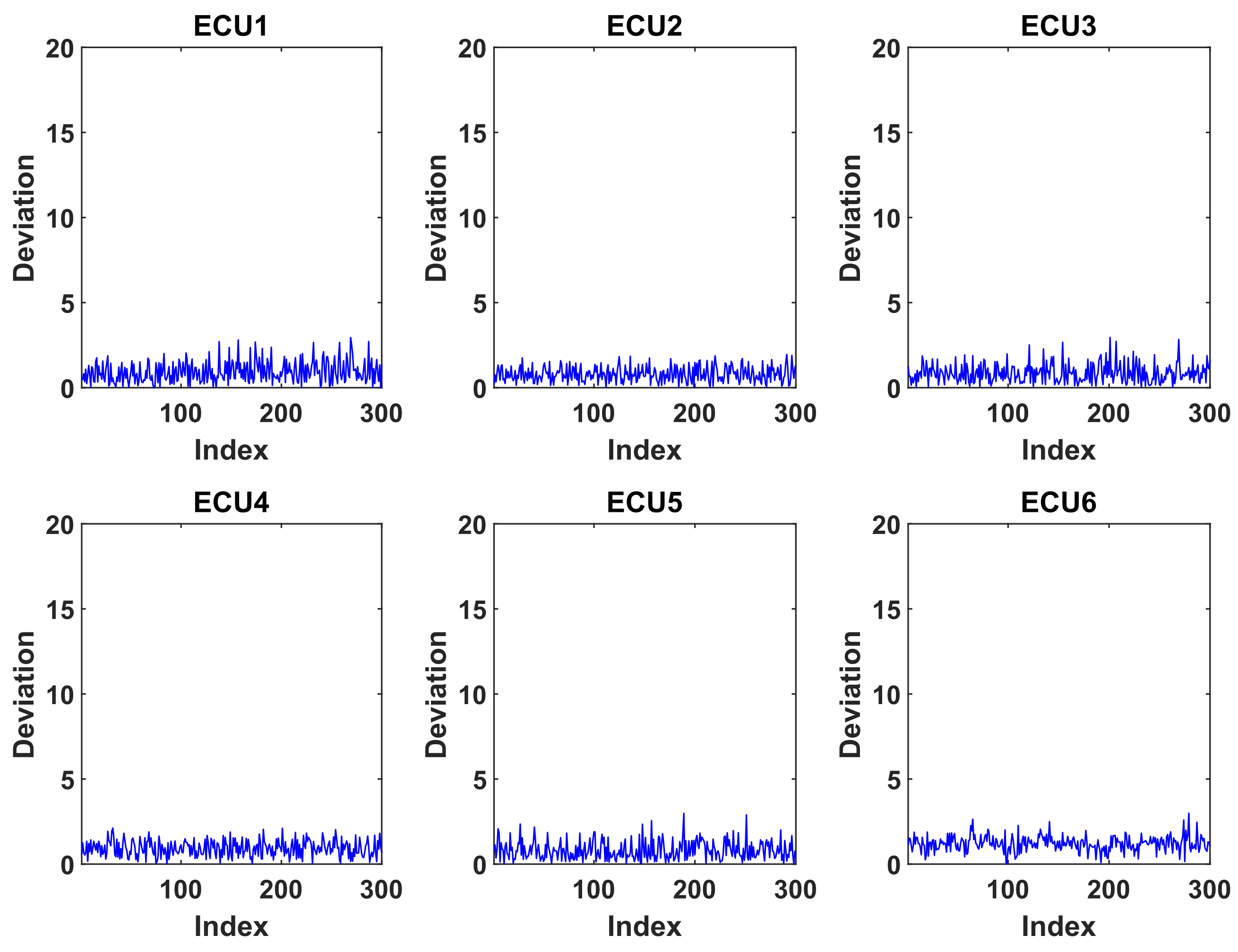
First, we analyze the changes in VHFs under different attack scenarios. This study collected the deviation of VHFs across diverse attack scenarios, as illustrated in Figure 9, Figure 10, Figure 11 and Figure 12. For comparative purposes, the deviation of VHFs under non-attack conditions was additionally acquired, as presented in Figure 13.
Figure 9.
Deviation Degrees of All ECUs When ECU 6 Is Subjected to a Substitution Attack.
Figure 10.
Deviation Degrees of All ECUs During ECU 5’s Masquerade Attack on ECU 2.
Figure 11.
Deviation Degrees of All ECUs During Injection Attack.
Figure 12.
Deviation Degrees of All ECUs During Wire-Tapping Attack.
Figure 13.
Baseline Deviation Degrees of All ECUs Under Non-Attack Conditions.
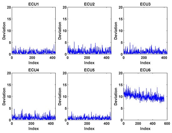
As can been seen from Figure 13, the VHF deviation of all ECU devices is less than 5, and the variance of deviation remains within a very low range under the no-attack scenario. However, upon the initiation of the substitution attack, as shown in Figure 9, a significant variation is observed in the VHF deviation of ECU 6, which rapidly surges to approximately 15—well above the normal value range. Meanwhile, the VHF deviations of the other ECUs remain nearly unchanged. This can be attributed to the inherent differences between the attacker’s and victim’s VHFs, coupled with the relatively limited overall impact of direct ECU replacement on the CAN-FD bus.
The same situation occurs in the masquerade attack, as shown in Figure 10. Due to the attacker’s manipulation of ECU 5 to impersonate ECU 2 and transmit forged messages over the CAN-FD bus, the VHF of ECU 2 became inherently conflated, leading to a significant fluctuation in the corresponding deviation metric. At the same time, the deviation of other ECUs did not change accordingly.
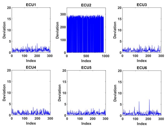
However, in the injection attack (see Figure 11), the introduction of counterfeit devices into the CAN-FD bus induces a significant alteration in the overall network impedance. Consequently, the mean deviation across all ECUs exhibits a substantial shift. Specifically, for ECU 6, the incorporation of false messages transmitted by the counterfeit devices results in dual distinct distributions in the fingerprints extracted from each frame, thereby leading to continuous fluctuations in the corresponding deviation metric. A analogous phenomenon was observed in the wire-tapping attack illustrated in Figure 12. Specifically, even without the introduction of counterfeit ECUs, the connection of unauthorized eavesdropping devices altered the overall bus impedance. This, in turn, induced fluctuations in the differential voltages of all ECUs, thereby leading to a substantial increase in the distance deviation metric. In conclusion, by verifying whether the distance deviation of all ECUs exceeds the predefined threshold, the current attack type can be effectively distinguished as either a substitution/masquerade attack or an injection/wire-tapping attack.
6.2.2. Attack Detection
Given that the distance threshold determines the ability to distinguish the legitimacy of individual frame messages and exerts a critical impact on the detection speed of attack scenarios, this study first evaluated the recognition accuracy across varying threshold settings.
Our test scenarios involve 200 cycles of switching between normal non-attack states and attack states, with each state transition performed 100 times in total. For each scenario, we compute the illegal rate of VHFs across 200 consecutive frames per ECU, and perform attack scenario identification as well as target detection in accordance with Algorithm 1. In the evaluation, the value of was set to 10%.
To systematically evaluate the threshold’s impact on practical deployment, we performed a sensitivity analysis across . As shown in Table 5, a low threshold () generates excessive false positives and false negatives, resulting in a relatively low attack detection rate. When , most attack types can be identified with near-perfect accuracy.
Table 5.
Overall Attack Detection Performance of Different Thresholds () Under Four Attack Scenarios.
However, IDS evaluation must go beyond raw accuracy and balance the trade-off between False Positive Rate (FPR) and False Negative Rate (FNR). A high FPR is especially problematic, as frequent false alarms may force the vehicle to unnecessarily enter a safe mode, degrading normal operational availability. As Table 5 illustrates, a low threshold such as is overly sensitive to normal electrical variations, leading to elevated false positives. In contrast, real physical-layer intrusions (e.g., module substitution or wire-tapping) introduce large impedance mismatches, which drive the deviation metric far beyond normal levels (typically ). Accordingly, choosing based on the statistical principle reduces FPR to nearly zero while preserving high detection effectiveness against real physical-layer attacks, thus achieving a suitable balance between security and operational stability.
We also conducted experiments to measure the running time under different scenarios. Experimental results from Table 5 show that our detection system can complete single-frame illegal detection in milliseconds and illegal attack detection within 1 s. Benefiting from effective feature selection and dimensionality reduction approaches (e.g., the integral interval process detailed in Section 4.2, Equation (1)), the identification time for legality/irregularity of a single CAN-FD signal frame is roughly 2 ms. Meanwhile, the detection time for the attack scenarios is also around 500 ms.
To clarify the two timing metrics in Table 5: Frame Identification time denotes the latency for processing a single isolated CAN-FD frame. With efficient dimensionality reduction, the low-level pipeline—including feature extraction, Mahalanobis distance computation, and legality verification against .
By contrast, Attack Identification time corresponds to the full traceability logic in Algorithm 1. Instead of a single frame, it relies on a sliding window of multiple frames (e.g., 200 frames per ECU) to compute stable statistics such as the illegal frame rate and . This metric covers both the physical accumulation of multiple frames and the subsequent system-wide decision tree processing for attack classification and compromised ECU localization.
In terms of training duration, the high sampling rate (i.e., 125 MHz) leads to an approximate 5 s time consumption for system training. These runtime metrics sufficiently demonstrate that our proposed detection model is highly suitable for resource-constrained CAN-FD networks.
6.2.3. Scalability Analysis
It is important to note that the computational overhead for intrusion detection is independent of the network size ( complexity). The system utilizes the CAN-FD ID to index and retrieve the unique corresponding fingerprint for a 1-to-1 verification. Consequently, the detection latency remains constant (about 2 ms) even in networks with 100+ ECUs. While the attack traceability logic (Algorithm 1) requires iterating through all known profiles ( complexity), the lightweight nature of the Mahalanobis distance calculation ensures that even 100 iterations can be executed within microseconds, without impacting real-time performance.
Beyond computational scalability, practical fleet deployment requires efficient lifecycle database maintenance. Since VHFs depend on physical hardware characteristics, routine Over-The-Air (OTA) firmware updates do not alter the ECU’s fingerprint, ensuring long-term database stability without post-update re-enrollment. However, physical ECU replacements necessitate a secure re-enrollment protocol (e.g., via the OBD-II port) by authorized personnel to register the new baseline fingerprint. Furthermore, for gradual environmental or aging shifts, our system implements an online adaptation mechanism. As will be detailed in Section 6.3.1, this function relies on a Maximum Drift Constraint (MDC) to continuously self-calibrate the database, significantly reducing fleet maintenance efforts.
6.3. Deviation Factors and Solutions
In this subsection, we first examined two potential factors—temperature and load rate—that contribute to VHF deviations of ECUs in the CAN-FD bus of real vehicles. On this basis, targeted solutions addressing the root causes of these deviations were further presented with necessary elaboration.
6.3.1. Temperature
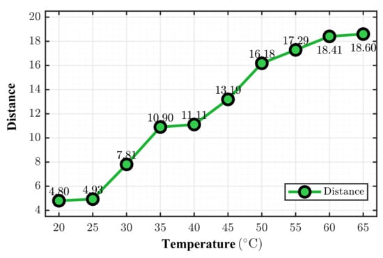
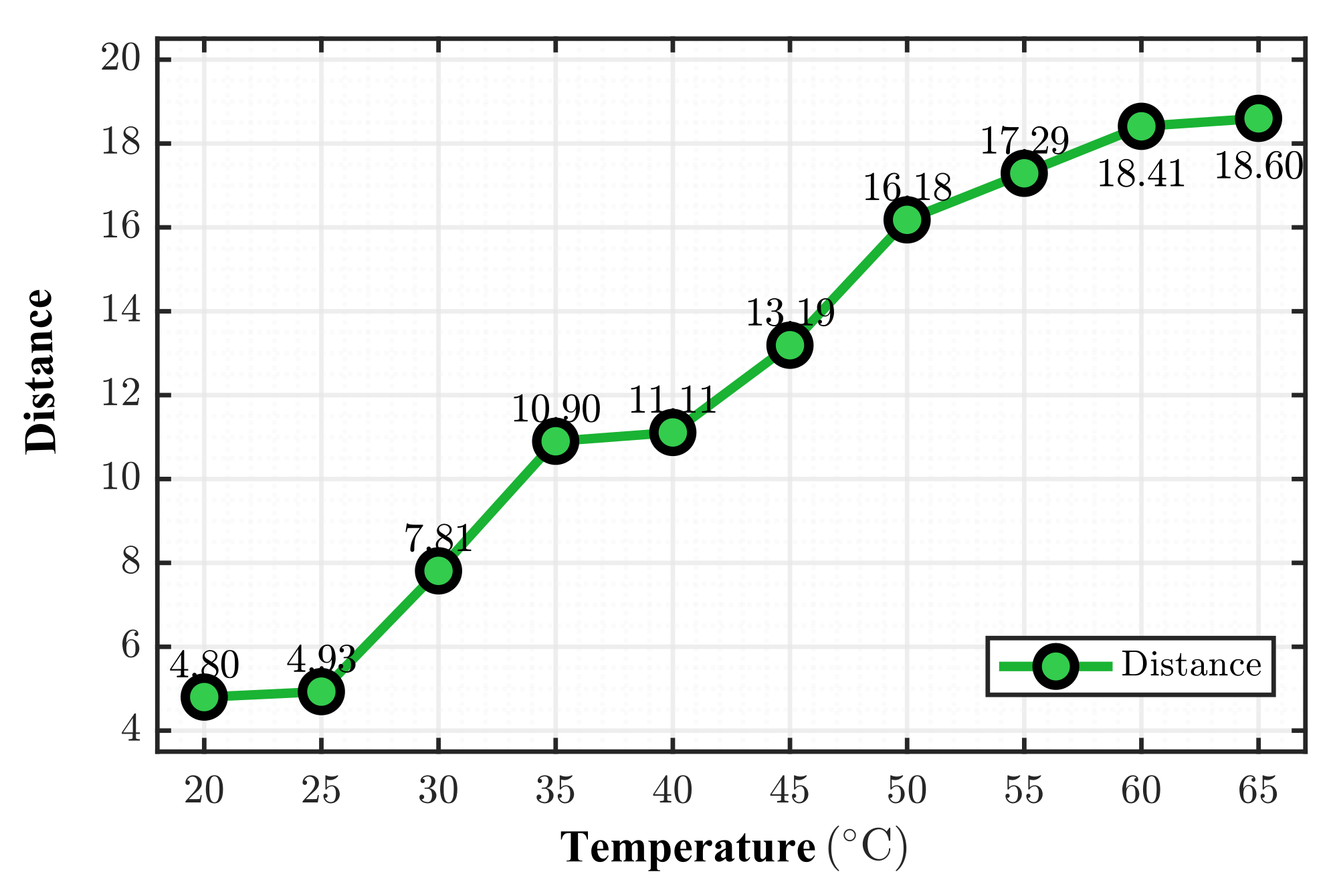
First, a temperature-dependent test was performed on CAN-FD nodes by placing them in a temperature-controlled platform, aiming to simulate the thermal behavior of vehicle ECUs (i.e., gradual temperature rise) during prolonged operation. The test protocol was initiated at 20 °C (the baseline for the VHF database) and increased in 5 °C steps up to 65 °C. ECUs transmitted messages continuously throughout the experiment. At each step, the system stabilized at the target temperature for 10 min to ensure thermal equilibrium of internal hardware before data sampling.
VHF deviation was quantified as the Mahalanobis distance between current signals and the 20 °C baseline (Figure 14). Thermal drift caused this distance to rise steadily with temperature, severely degrading detection accuracy if unaddressed. With an anomaly threshold , the distance reached 7.81 at 30 °C and 10.90 at 35 °C—breaching the decision boundary and triggering an unacceptable surge in FP by misclassifying legitimate frames as malicious. To resolve this, we integrated a timely VHF database update function.
Figure 14.
The Influence of Temperature on VHFs. The Node Being Measured is ECU 6.
The detailed procedure for a VHF database update is as follows: Upon system operation, real-time monitoring of the CAN network is performed. If any illegal devices are detected, the update process is suspended. In the absence of illegal devices, the mean value of distance deviation for one node over the latest 100 frames is computed. When the mean value falls within the range of threshold to , a candidate update for the VHF database is generated.
However, to prevent “slow poisoning” attacks—where a patient adversary intentionally induces gradual shifts to maliciously alter the reference database without triggering immediate alarms—we introduce MDC. The system securely retains the initial enrollment fingerprint () captured during a trusted startup as a permanent anchor. The VHF database is updated to the new candidate fingerprint () only if the total distance between and strictly remains below a maximum physical limit ().
As evidenced in Figure 14, the legitimate thermal drift is physically bounded. By setting just above this empirical maximum, the system successfully accommodates normal environmental variations while fundamentally preventing an attacker from indefinitely shifting the database toward a malicious hardware profile. If the boundary is breached, the update is rejected and an anomaly alarm is triggered.
6.3.2. Data-Load Rate
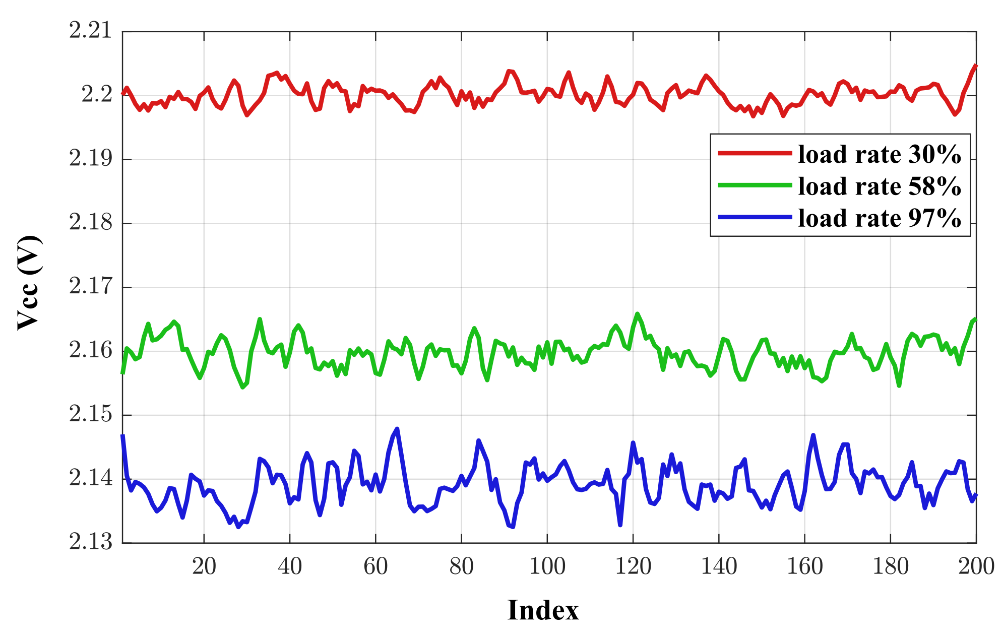
We also found that the load rate of the CAN-FD bus would affect the distribution shift of VHF. If an attacker modifies the transmission rate of an ECU device, it will alter the message load rate of the bus. Consequently, the voltage value of the messages sent by the ECU will also change to a certain extent. The corresponding result is illustrated in Figure 15. To address this issue, our system monitor the total bus traffic in real time and dynamically adjust the VHF distance threshold based on the traffic volume. When the bus traffic deviates from that during the training period, the threshold for determining the legitimacy of a single-frame message can be dynamically adjusted upward.
Figure 15.
The Influence of Bus Load Rate on Voltage Level.
We further clarify the impact of dynamic threshold adjustment on detection performance, specifically FPs and FNs. Without adjustment, high traffic loads (e.g., 97%) induce a voltage drop that pushes the Mahalanobis distance of legitimate frames beyond the baseline threshold (), causing excessive FPs. However, dynamic threshold relaxation preserves security (no FN increase) via a large Attack Separation Margin: maximum load fluctuations only shift the deviation metric V to approximately 8, whereas physical intrusions (e.g., injection or wire-tapping) cause drastic impedance mismatches, driving . Thus, upward threshold adjustment under high loads perfectly suppresses FPs while maintaining full sensitivity to real attacks, ensuring robust classification stability across all load conditions.
6.4. Limitations and Future Work
Although our study effectively mitigates short-term thermal drift, we explicitly recognize the system’s limitations under extreme operational conditions. In practical automotive scenarios, extreme environmental stressors—such as severe electromagnetic interference (EMI) events or long-term transceiver aging—may cause non-linear circuit deformations, which could potentially trigger false detection alarms [2]. As such, while a full investigation of long-term aging effects is beyond the scope of the present work, it represents an important target for our future research.
To address these limitations and further strengthen in-vehicle security, our future research will focus on three key directions: (1) developing AI-driven adaptive thresholding mechanisms to autonomously track long-term environmental baselines; (2) designing multi-modal fingerprinting techniques that fuse voltage characteristics with other physical-layer metrics (e.g., clock skew) to enhance robustness against complex noise; (3) integrating lightweight cryptographic primitives (e.g., lightweight message authentication codes (MACs)) to establish a holistic defense-in-depth architecture.
7. Conclusions
In this paper, we have presented a lightweight ECU identification and intrusion detection scheme for CAN-FD networks. By leveraging the distinct voltage and edge characteristics inherent in the control and data fields to construct hardware fingerprints, the proposed method effectively facilitates the identification of compromised ECUs across diverse attack scenarios. To validate the proposed solution, a 6-node CAN-FD experimental platform was established, and typical spoofing attacks as well as other wire-tapping attack scenario (which are notoriously challenging for conventional IDS solutions to detect) were meticulously designed. Experimental results demonstrate that the proposed scheme can promptly identify malicious attack types and rapidly locate compromised devices. Consequently, this solution significantly enhances the security of CAN-FD networks and exhibits feasibility in prototype environments.
Author Contributions
Conceptualization, Y.Y. and R.Z.; data curation, J.Y.; supervision, Y.D. All authors have read and agreed to the published version of the manuscript.
Funding
This work was supported in part by the National Science and Technology Major Projects of China (2025ZD1303100) and Wuxi University Research Start-up Fund for Introduced Talents (2024r087).
Data Availability Statement
The data that support the findings of this study are available from the corresponding author upon reasonable request.
Conflicts of Interest
The authors declare no conflicts of interest.
References
- Jeong, W.; Han, S.; Choi, E.; Lee, S.; Choi, J.W. CNN-based adaptive source node identifier for controller area network (CAN). IEEE Trans. Veh. Technol. 2020, 69, 13916–13920. [Google Scholar] [CrossRef] [Scilit]
- Yu, Z.; Liu, Y.; Li, R.; Chang, W. LIDS: A lightweight intrusion detection system for controller area network. IEEE Trans. Comput.-Aided Des. Integr. Circuits Syst. 2025, 44, 3303–3312. [Google Scholar] [CrossRef] [Scilit]
- Huang, C.; Wang, J.; Yan, S.; He, D. Exploring factors related to drivers’ mental model of and trust in advanced driver assistance systems using an ABN-based mixed approach. IEEE Trans. Hum.-Mach. Syst. 2024, 54, 646–657. [Google Scholar] [CrossRef] [Scilit]
- ISO 11898; Road Vehicles–Controller Area Network (CAN)–Part 1: Data Link Layer and Physical Signalling. ISO: Geneva, Switzerland, 2003.
- Zeltwanger, H. CAN Standard Review: Changes and Enhancements of the ISO 11898; SAE Technical Paper 2000-01-0143; SAE Standard: Warrendale, PA, USA, 2000. [Google Scholar] [CrossRef] [Scilit]
- Rishiwal, V.; Agarwal, U.; Alotaibi, A.; Tanwar, S.; Yadav, P.; Yadav, M. Exploring secure V2X communication networks for human-centric security and privacy in smart cities. IEEE Access 2024, 12, 26850–26868. [Google Scholar] [CrossRef] [Scilit]
- Hakeem, S.A.A.; Kim, H. Advancing intrusion detection in V2X networks: A comprehensive survey on machine learning, federated learning, and edge AI for V2X security. IEEE Trans. Intell. Transp. Syst. 2025; Early Access. [CrossRef] [Scilit]
- Miller, C.; Valasek, C. Remote exploitation of an unaltered passenger vehicle. Proc. Black Hat USA 2015, 2015, 1–91. [Google Scholar]
- Agbaje, P.; Olufowobi, H.; Hounsinou, S.; Bloom, G. From Weeping to Wailing: A transitive stealthy bus-off attack. IEEE Trans. Intell. Transp. Syst. 2024, 25, 12066–12080. [Google Scholar] [CrossRef] [Scilit]
- Park, J.; Lee, M.; Park, S.; Kim, J.; Kim, J.; Kim, D. Controller area network with flexible data rate (CAN FD) eye diagram prediction. IEEE Trans. Electromagn. Compat. 2024, 66, 949–959. [Google Scholar] [CrossRef] [Scilit]
- Ma, W.; Liu, Y.; Xie, G.; Li, R.; Yang, L.T. Security-aware CAN-FD message packing in intelligent automotive cyber–physical systems. IEEE Internet Things J. 2022, 9, 22343–22356. [Google Scholar] [CrossRef] [Scilit]
- Groza, B.; Murvay, P.S. Security solutions for the controller area network: Bringing authentication to in-vehicle networks. IEEE Veh. Technol. Mag. 2018, 13, 40–47. [Google Scholar] [CrossRef] [Scilit]
- Almehdhar, M.; Albaseer, A.; Khan, M.A.; Abdallah, M.; Menouar, H.; Al-Kuwari, S.; Al-Fuqaha, A. Deep learning in the fast lane: A survey on advanced intrusion detection systems for intelligent vehicle networks. IEEE Open J. Veh. Technol. 2024, 5, 869–906. [Google Scholar] [CrossRef] [Scilit]
- Murvay, P.S.; Groza, B. TIDAL-CAN: Differential timing based intrusion detection and localization for controller area network. IEEE Access 2020, 8, 68895–68912. [Google Scholar] [CrossRef] [Scilit]
- Liu, Y.; Xue, L.; Wang, S.; Luo, X.; Zhao, K.; Jing, P.; Ma, X.; Tang, Y.; Zhou, H. Vehicular intrusion detection system for controller area network: A comprehensive survey and evaluation. IEEE Trans. Intell. Transp. Syst. 2025, 26, 10979–11009. [Google Scholar] [CrossRef] [Scilit]
- Zhang, T.; Du, C.; Zhou, Y.; Guan, Q.; Liu, Z.; Huang, X.; Gong, Z.; Deng, L.; Li, Y. Hybrid transfer and self-supervised learning approaches in neural networks for intelligent vehicle intrusion detection and analysis. IEEE Internet Things J. 2025, 12, 7677–7692. [Google Scholar] [CrossRef] [Scilit]
- Nazat, S.; Li, L.; Abdallah, M. XAI-ADS: An explainable artificial intelligence framework for enhancing anomaly detection in autonomous driving systems. IEEE Access 2024, 12, 48583–48607. [Google Scholar] [CrossRef] [Scilit]
- Levy, E.; Shabtai, A.; Groza, B.; Murvay, P.S.; Elovici, Y. CAN-LOC: Spoofing detection and physical intrusion localization on an in-vehicle CAN bus based on deep features of voltage signals. IEEE Trans. Inf. Forensics Secur. 2023, 18, 4800–4814. [Google Scholar] [CrossRef] [Scilit]
- Wang, X.; Liu, Y.; Meng, L.; Liu, P.; Qu, Y.; Fan, X.; Liu, T. Passive localization for silent intrusion device in fieldbus network based on reflection-based group fingerprint. IEEE Trans. Instrum. Meas. 2025, 74, 6511216. [Google Scholar] [CrossRef] [Scilit]
- Dini, P.; Soldaini, E.; Saponara, S. Design and test of an embedded real-time compact voltage fingerprinting algorithm for enhanced automotive cybersecurity. IEEE Access 2025, 13, 73183–73201. [Google Scholar] [CrossRef] [Scilit]
- Dang, L.; Hapuarachchi, T.; Xiong, K.; Li, Y. SDN-based false data detection with its mitigation and machine learning robustness for in-vehicle networks. arXiv 2025, arXiv:2506.06556. [Google Scholar] [CrossRef] [Scilit]
- Islam, M.R.; Sahlabadi, M.; Kim, K.; Kim, Y.; Yim, K. CF-AIDS: Comprehensive frequency-agnostic intrusion detection system on in-vehicle network. IEEE Access 2024, 12, 13971–13985. [Google Scholar] [CrossRef] [Scilit]
- Cho, K.T.; Shin, K.G. Fingerprinting electronic control units for vehicle intrusion detection. In Proceedings of the 25th USENIX Security Symposium (SEC), Austin, TX, USA, 10–12 August 2016; pp. 911–927. Available online: https://www.usenix.org/conference/usenixsecurity16/technical-sessions/presentation/cho (accessed on 30 January 2026).
- Ying, X.; Sagong, S.U.; Clark, A.; Bushnell, L.; Poovendran, R. Shape of the cloak: Formal analysis of clock skew-based intrusion detection system in controller area networks. IEEE Trans. Inf. Forensics Secur. 2019, 14, 2300–2314. [Google Scholar] [CrossRef] [Scilit]
- Zhang, J.; Li, J.; Jiang, R.; Li, F. Multi-dimensional clock fingerprinting for abnormal ECU sourcing in CAN bus. In Proceedings of the IEEE Wireless Communications and Networks Conference (WCNC), Dubai, United Arab Emirates, 21–24 April 2024; pp. 1–6. [Google Scholar] [CrossRef] [Scilit]
- Wei, H.; Ai, Q.; Zhai, Y.; Zhang, Y. Automotive security: Threat forewarning and ECU source mapping derived from physical features of network signals. IEEE Trans. Intell. Transp. Syst. 2024, 25, 2479–2491. [Google Scholar] [CrossRef] [Scilit]
- Murvay, P.S.; Groza, B. Source identification using signal characteristics in controller area networks. IEEE Signal Process. Lett. 2014, 21, 395–399. [Google Scholar] [CrossRef] [Scilit]
- Avatefipour, O.; Hafeez, A.; Tayyab, M.; Malik, H. Linking received packet to the transmitter through physical-fingerprinting of controller area network. In Proceedings of the IEEE Workshop on Information Forensics and Security (WIFS), Rennes, France, 4–7 December 2017; pp. 1–6. [Google Scholar] [CrossRef] [Scilit]
- Avatefipour, O. Physical-Fingerprinting of Electronic Control Unit (ECU) Based on Machine Learning Algorithm for In-Vehicle Network Communication Protocol “CAN-BUS”. Ph.D. Thesis, University of Michigan-Dearborn, Dearborn, MI, USA, 2017. [Google Scholar]
- Hafeez, A.; Tayyab, M.; Zolo, C.; Awad, S. Finger printing of engine control units by using frequency response for secure in-vehicle communication. In Proceedings of the 14th International Computer Engineering Conference (ICENCO), Cairo, Egypt, 29–30 December 2018; pp. 79–83. [Google Scholar] [CrossRef] [Scilit]
- Zhang, J.; Gong, B.; Waqas, M.; Tu, S.; Chen, S. Many-objective optimization based intrusion detection for in-vehicle network security. IEEE Trans. Intell. Transp. Syst. 2023, 24, 15051–15065. [Google Scholar] [CrossRef] [Scilit]
- Wei, H.; Ai, Q.; Zhao, W.; Zhang, Y. Real-time security warning and ECU identification for in-vehicle networks. IEEE Sens. J. 2023, 23, 20258–20266. [Google Scholar] [CrossRef] [Scilit]
- Zhou, J.; Xie, G.; Zeng, H.; Zhang, W.; Yang, L.T.; Alazab, M.; Li, R. A model-based method for enabling source mapping and intrusion detection on proprietary CAN bus. IEEE Trans. Intell. Transp. Syst. 2023, 24, 12922–12932. [Google Scholar] [CrossRef] [Scilit]
- Zhang, Z.; Yang, K.; Tian, Y.; Ma, J. An Anti-Disguise Authentication System Using the First Impression of Avatar in Metaverse. IEEE Trans. Inf. Forensics Secur. 2024, 19, 6393–6408. [Google Scholar] [CrossRef] [Scilit]
- Cho, K.T.; Shin, K.G. Viden: Attacker identification on in-vehicle networks. In Proceedings of the ACM SIGSAC Conference on Computer and Communications Security, Dallas, TX, USA, 30 October–3 November 2017; pp. 1109–1123. [Google Scholar] [CrossRef] [Scilit]
- Popa, L.; Groza, B.; Jichici, C.; Murvay, P.S. ECUPrint—Physical fingerprinting electronic control units on CAN buses inside cars and SAE J1939 compliant vehicles. IEEE Trans. Inf. Forensics Secur. 2022, 17, 1185–1200. [Google Scholar] [CrossRef] [Scilit]
- Woo, S.; Jo, H.J.; Kim, I.S.; Lee, D.H. A practical security architecture for in-vehicle CAN-FD. IEEE Trans. Intell. Transp. Syst. 2016, 17, 2248–2261. [Google Scholar] [CrossRef] [Scilit]
- De Andrade, R.; Hodel, K.N.; Justo, J.F.; Laganá, A.M.; Santos, M.M.; Gu, Z. Analytical and experimental performance evaluations of CAN-FD bus. IEEE Access 2018, 6, 21287–21295. [Google Scholar] [CrossRef] [Scilit]
- Zhao, Y.; Xun, Y.; Liu, J. ClockIDS: A real-time vehicle intrusion detection system based on clock skew. IEEE Internet Things J. 2022, 9, 15593–15606. [Google Scholar] [CrossRef] [Scilit]

Disclaimer/Publisher’s Note: The statements, opinions and data contained in all publications are solely those of the individual author(s) and contributor(s) and not of MDPI and/or the editor(s). MDPI and/or the editor(s) disclaim responsibility for any injury to people or property resulting from any ideas, methods, instructions or products referred to in the content. |
© 2026 by the authors. Licensee MDPI, Basel, Switzerland. This article is an open access article distributed under the terms and conditions of the Creative Commons Attribution (CC BY) license.