Abstract
In the current situation of the Internet of Things (IoT) with its billions of interconnected devices, security in this low-resource environment is paramount. A Physical Unclonable Function (PUF) is a very useful cryptographic primitive which allows us to extract unique information from a particular device in a non-reproducible way. This allows us to use a PUF in cryptography for authentication or secret-key generation. Ring Oscillators (ROs) and Transient Effect Ring Oscillators (TEROs) are oscillating structures used in both FPGAs and ASICs to build PUFs. In this paper we present an FPGA implementation of a PUF based on what we call the “TERORO” cell (TERO + RO), which is a hybrid structure that allows us to use the different functionalities of both RO and TERO in a single building block. We assess all the possible methods of extracting bits of information from the PUF based on TERORO cells. Finally, we tested the circuit and presented experimental results in terms of its uniqueness, uniformity, and reliability. In RO-counter mode, we obtain uniqueness, uniformity, and reliability across devices, while TERO-based XOR mixing achieves uniformity, uniqueness, and reliability. The FPGA footprint is 142 LUTs, 36 registers, and 82 slices.
1. Introduction
A great number of devices are connected on the Internet of Things (IoT) in the modern world, with projections estimating that 75% of devices will be integrated in the IoT by 2030 [1]. Cryptography is paramount to achieving privacy, secure communications, and robust implementations against malicious attacks. In this context, the large amount of devices and the limited resources require some solution to achieve a secure and low-resource way to achieve identification, authentication, and secret-key generation. According to [2], many of the IoT devices are made of cheap embedded devices that do not include hardware security features, which poses a threat that must be addressed.
Physical Unclonable Functions (PUFs) have recently gained attention as a key block for these purposes again [3,4], although they were introduced earlier, in the beginning of the twenty first century [5]. There are several types of PUFs that vary depending on the physical substrate on which they are implemented, but in the context of integrated circuits, silicon PUFs use their manufacturing variations to extract information about a particular instance of a circuit, which are random and unpredictable.
This work targets low-resource IoT devices where secure non-volatile memory is unavailable or undesirable. In such memoryless scenarios, PUFs enable device-specific secrets to be derived on demand, supporting primitives such as authentication and key establishment without storing long-term keys. Recent works [6] also highlight combining PUFs and True Random Number Generators (TRNGs) to cover the full set of security primitives in memoryless IoT systems. While TRNG design and validation are outside the scope of this paper, we note that RO/TERO-based inverter-chain structures are often leveraged as entropy sources with limited additional hardware overhead.
The way a PUF works is by applying a challenge, a certain input bit-string, and retrieving a unique response, another output bit-string, by evaluating the PUF. A set of a challenge and its pertaining response is commonly known in the literature as a Challenge–Response Pair (CRP). A PUF is commonly referred to as strong when the number of CRPs supported by the construction scales exponentially with the PUF size, whereas weak PUFs typically exhibit linear or polynomial CRP scaling with size [7].
According to [8] the main use of weak PUFs is to generate a device-unique identifier or fingerprint that will be the input to some cryptographic function, since the number of CRPs is low. Strong PUFs can be used in authentication mechanisms without extra hardware dedicated to this purpose. In both cases, the response must be reliable and unique to each device, so that duplicating the circuit in another instance reports to the attacker no information at all.
One drawback of strong PUFs is that they are especially vulnerable to machine learning (ML) attacks because the large amount of CRPs gives the attacker an opportunity to train a model that will predict the response of the PUF for a given unknown challenge. In [9] the concept of controlled PUFs is explained as the addition of some control logic to a strong PUF so that challenges cannot be freely applied to it. This hinders the direct reading of the PUF response and can be useful in frustrating ML attacks.
It is common to find in the scientific literature PUF designs based on Ring Oscillators (ROs). These structures consist of a concatenated loop of logical inverters (see Figure 1) which produce a certain frequency oscillation depending on the total sum of the delays of each gate in the loop. The variation in the delays of the inverters, specific for each implementation, gives a different frequency oscillation for each PUF. They are a solid option for a PUF since they are easily implemented in digital designs and they occupy a small area, but their oscillation frequencies can be measured because of the electromagnetic radiation they emit, and this can be used to perform a side-channel attack [10]. Another drawback is the high sensibility to environmental variations in temperature and voltage [11].
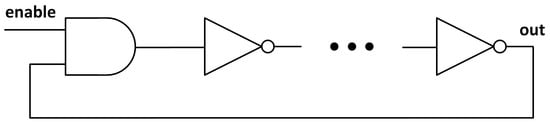
Figure 1.
Schematic of a RO with an enable signal. The number of inverters must be odd in order to have an oscillation.
There have been several proposals presented recently on PUF based on Transient Effect Ring Oscillator (TERO) [12,13]. These oscillators are similar to ROs, but they have an even number of inverting stages, so the oscillation cannot last indefinitely. In the case of a RO, the system cannot reach a stable state once the enable signal has been set, but in the case of the TERO (see Figure 2), the enable signal sets a “race” between the upper and the lower branch that will produce an oscillating state until the signal collapses to a stable state. There are two possible states for the collapsed signal, either a logic ‘1’ in the upper branch and a ‘0’ in the lower branch, or vice versa.
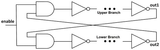
Figure 2.
Schematic of a TERO with an enable signal. The number of inverters in each branch must be odd in order to have an unstable state which will be solved when the enable signal is activated.
Notice that, in order to have a TERO, we must have an odd number of inverters in both the upper and the lower branch (which, in total, gives an even number); otherwise, the structure would have a state that it is already “resolved” and there will be no oscillation. For illustrating this, consider the case of a TERO with two inverters per branch (see Figure 3). When the enable signal is set to ‘0’, the input of the first inverter will be a ‘0’, the input for the second inverter will be a ‘1’, and the output of the second inverter, which is the input of the AND gate of the opposite branch, will be a ‘0’ again. In this case, setting the enable signal to ‘1’ does nothing, since the input of the first inverter is already ‘0’ and the circuit will not oscillate. But for an odd number of inverters per branch, the output of the last inverter (input of the AND gates) will be a ‘1’ when the enable signal is ‘0’. So when the enable signal is set to ‘1’, the input of the first inverter will change from ‘0’ to ‘1’ and an oscillation will start until the circuit is stabilised. Then, when setting the enable signal to ‘0’ again, the prior unstable state will be set and the oscillation can be initialised again by changing the enable signal again.
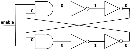
Figure 3.
Impossible TERO structure with an even number of inverters per branch. Notice that changing the enable signal does nothing, since the state is already stable.
Both the number of oscillations of the TERO and the value of the output after the oscillation has collapsed can be used for extracting a response for a PUF. This type of PUF is more resistant to electromagnetic side-channel attacks because the short duration of the oscillation makes it more difficult to measure. Nevertheless, in some cases, it is possible to measure the number of oscillations in a TERO [14,15]. The collapse value cannot be known for the attacker, unless this value is stored temporally in a memory unit and then this memory is reset, something similar to the behaviour observed in [16]. Beyond passive electromagnetic observation, RO/TERO-like inverter-chain structures may also be susceptible to intentional electromagnetic injection/fault attacks, which we do not evaluate here and leave as future work.
In this paper, we implement a new PUF architecture based on a combination of a TERO and RO, called “TERORO-PUF”, described in Section 2, with the aim of taking advantage of both RO and TERO proposals. An assessment of the different parameters for the performance evaluation of PUFs is shown in Section 3. The different modes of operation of the TERORO-PUF are explained in Section 4. A physical implementation in FPGA of the TERORO-PUF is presented in Section 5 and its different evaluation methods are tested. In Section 6 we present the variation of the PUF response with temperature. We compare the results of this PUF with other similar implementations in Section 7. In Section 8 the conclusions of the paper are drawn.
In practical terms, the proposed TERORO-PUF can support (i) device authentication/ anti-counterfeiting in low-cost IoT nodes, (ii) on-demand key derivation for secure channel bootstrapping without storing long-term secrets, (iii) secure provisioning/pairing during manufacturing or enrolment, and (iv) an entropy component alongside lightweight TRNG designs (not evaluated here). The same configurable cell also enables evaluating multiple extraction modes under a unified FPGA footprint, which is attractive when area and power are constrained.
2. Proposed Design: TERORO-PUF
The configurable RO-PUF was firstly introduced in [17] as a way of improving the reliability of the RO-PUF. There are recent proposals on configurable PUFs in the literature, like the RO-PUFs presented in [18,19,20], or the TERO-PUFs in [21,22,23,24]. This is convenient since the same structure can be used several times by applying multiple challenges to the same cell, thus yielding more response bits without extra area overhead. Also, if the configurability is large enough (the length of the challenge bit-string), the RO-PUF or TERO-PUF can be used as a strong PUF. Regarding timing considerations, the loop is intentionally asynchronous and timing closure is applied to the synchronous readout path (we isolate the oscillator core and sample via counters). Evaluation latency is dominated by the counter fill time in RO mode or the wait-for-collapse window in TERO mode. Because of this, increasing the number of stages does not create long synchronous critical paths in the readout interface.
Our goal is to use a TERO-like configurable structure as both TERO and RO in different modes of operation, all with the same basic cell, thus adding configurability and complexity to the PUF without extra hardware. This idea was first presented in our prior work [25] as a theoretical design and now in this paper we aim to test it in a real FPGA implementation to assess the performance metrics and the hardware overhead. In a classical TERO-PUF there are TEROs, selectors, and counters. The same structure can be used to implement a RO-PUF, we just need to configure the TERO configurable cell with an odd number of inverting stages, having then an unending oscillation, which is a RO in practice. Combining the names of TERO and RO, we have called this the TERORO-PUF, for it has both functionalities in the same pack.
In [26] the authors show an interesting configurable structure that can also be used as both RO and TERO depending on the number of inverting stages. Nevertheless, they only use one type of evaluation method per configuration (one for the RO mode and another for the TERO mode), but in this paper, we aim to use all of the possible methods of evaluation that can be exploited in the same cell. These will be explored in Section 4.
In order to achieve a structure that can behave as both TERO and RO, we need to be able to select the number of inverting stages. In Figure 4 we see an example of a configurable TERO structure that can be used both as a TERO and as a RO, and it is similar to the configurable RO shown in [27]. The configuration input will determine the behaviour of the structure. For example, in a TERORO of 3 stages, configuration {CONF1,CONF2} = ‘101001’ will set the upper branch to an inverter–buffer–inverter (‘101’) array, while the lower branch will be set to a buffer–buffer–inverter (‘001’) array, making a RO structure because the total of inverting stages is odd. If the configuration is, for example, ‘100100’ this will set both the upper and lower branches to an inverter-buffer-buffer array, making a TERO structure because the number of inverting stages is even.
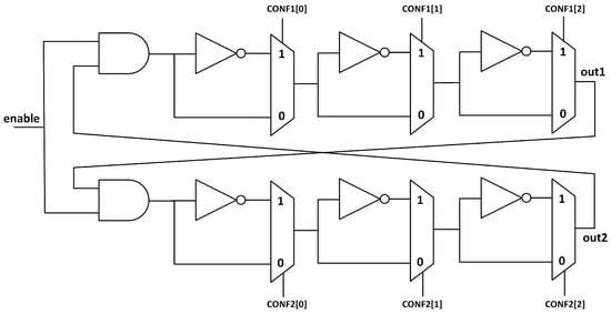
Figure 4.
Configurable TERO cell with multiplexers and inverters. Each stage can be configured as an inverter stage or not.
The length of the stages in the TERORO cell determines all possible combinations of configurations. For short TERORO cells, that is, few stages, a weak PUF will be implemented because there will be a small number of possible CRPs. For long TERORO cells, that is, many stages, a strong PUF can be implemented for the CRP space and it will be large enough to have sufficient configurations so that they cannot be evaluated in a finite amount of time (the amount of CRPs increases exponentially with the number of stages).
In Figure 5 there is another example on how this configurable structure can be built using XOR gates. Comparing Figure 4 and Figure 5, the behaviour in both is approximately the same. In the multiplexer case an additional delay is introduced when inverting, since two gates are added to the path, the inverter and the multiplexer, compared with the alternative configuration of bypassing the signal through the multiplexer only. This makes the frequency of the oscillator depend on the number of inverting stages, unless a buffer is added in the non-inverting path. By using XOR gates with one of its inputs as a configuration input, we have the possibility to choose whether the XOR will be inverting the signal on the other input or not. We could say that we can choose whether the XOR gate will behave as an inverter or as a buffer. In this case there is always one gate per stage, so the frequency will be practically independent from the number of inverting stages.
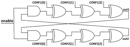
Figure 5.
Configurable TERO cell with XOR gates. Each stage can be configured as an inverter stage or not, since XOR gates act as a buffer or inverter for one of its inputs depending on the value of the other input.
Because the XOR structure uses less LUTs in a FPGA implementation and there is no frequency dependence with the configuration bit-string, we prefer this one over the MUX structure to implement the TERORO cell.
In [23] the authors show a proposal for a strong configurable TERO cell using double XOR gates instead of the typically used inverter. It is similar to the architecture in Figure 5, but the difference is that XOR gates are grouped in pairs and share the same configuration input, ensuring that all configurations always form a TERO. By doing this, they achieve a way of configuring the stages of the TERO so that it is no longer a weak PUF but a strong one, since now several challenges can be applied to the same cell and its number will escalate exponentially with the number of stages. Our proposal is to use a similar architecture, but instead of using double XORs, we will use single separate XORs, so that the structure can behave as a configurable TERO but also as a configurable RO.
To summarise, in the literature, there are already proposals of configurable TEROs and ROs, weak and strong, and our prior work in [25] was a proposal to use the configurable TERO structure to merge both TERO and RO functionalities in the same cell. The novelty of this paper is to implement this hybrid design in FPGA to test its viability in a real application and to present quantifiable PUF quality metrics and resource utilisation.
3. Characterisation of PUF
There are several important metrics that characterise the quality of a PUF. In [28], four different parameters that evaluate the security and viability of a PUF are presented. We add a fifth parameter which we have called stability. Note that all metrics in (1)–(5) are defined in the [0, 1] range and are reported as percentages (×100) in the tables and figures and in the rest of the paper.
3.1. Uniqueness
The uniqueness of a PUF is related to the ability to differentiate its response from the same PUF in another device with the same configuration. This is vital for the unclonability purposes of a PUF. If several PUF responses are too similar in different devices, the security of the PUF decreases because it will be predictable. To evaluate the uniqueness, the Hamming Distance (HD) between the responses of several PUFs is used. For d different devices that produce an n-bit response , the average uniqueness is computed with the following expression:
The ideal value for average uniqueness is .
3.2. Reliability
The reliability of a PUF represents the repeatability of the response of a PUF when evaluated several times on the same device with the same configuration on different environmental conditions (temperature, voltage, etc.). If a PUF response is not reliable, this may affect the usability of the PUF. In reality there are no 100% reliable PUFs, since there is always some component of noise or instability of any type. This is why error-correction codes are widely used as a method for improving the reliability of a PUF [29], but the cost is that the length of the output bit-string must be reduced. Thus, high reliability will reduce the cost of the PUF implementation, and low reliability will increase it, even to the point that it is not useable in realistic conditions. Reliability is computed using the intra-HD, that is, the HD between several evaluations of the PUF response in the same device under several conditions. For a reference response n-bit long of a certain device, , at normal operating conditions, and s samples of responses in different operating conditions , the reliability of a PUF in a certain device is computed by the following expression:
Ideally, this parameter should be .
3.3. Uniformity
The uniformity of a PUF states how equal is the proportion of ‘1’ s and ‘0’ s in the bits of the response. The PUF response should be totally random and the bits of the response should not be biased towards ‘0’ or ‘1’. With being the bit in position k of the n-bit PUF response in device i, uniformity is computed by calculating the Hamming weight of the response as follows:
The ideal value of the uniformity of a PUF response is .
3.4. Bit-Aliasing
Bit-aliasing is the propensity of the bits in concrete positions of the PUF response to be biased toward a certain value, ’1’ or ’0’, among several devices for the same configuration. It is the average value of the bit in position k of the n-bit PUF response, , along d devices. We compute it by the following expression:
Ideally, bit-aliasing should be .
3.5. Stability
This parameter does not appear in [28], but we have defined it in this paper to gain a deeper understanding on the behaviour of the responses. It is closely related with the reliability, and it shows the amount of bits in a response that have a reliability higher than a certain arbitrary threshold. With being the reference value of the bit in position k of the n-bit PUF response, is the value of the same bit in a different condition t across s total samples, Y is the threshold of stability we want to apply, and considering the output of the ‘≥’ operator as ‘0’ if false and as ‘1’ if true, we mathematically define stability as follows:
Ideally, stability should be .
In this paper we compute stability with a threshold, which shows the percentage of bits in a certain response that have a reliability higher than or equal to . This parameter is useful because error-correction mechanisms [29] sometimes use a selection algorithm whereby the least reliable bits are discarded, so we can have an idea of the proportion of the bits that would be discarded.
4. Modes of Operation of the TERORO-PUF
In this section we explore the possible modes of operation of the TERORO-PUF, considering that there are at least two binary counters and a selection mechanism to compare two TERORO cells. An example architecture for the full TERORO-PUF with all the possibilities for evaluation methods is shown in Figure 6. Two banks of TERORO cells are used in this example, each with its own counter, although more of them could be used to increase parallelisation. It is not shown in the figures, but a buffer should be added to both of the outputs of each TERORO cell to uncouple the feedback wire of the TERORO cell from the rest of the circuit. By doing this we ensure that no extra capacitance is added to any of the branches of the cell. We present the possible methods, but is up to the user to use either one, several, or all of them at the same time.
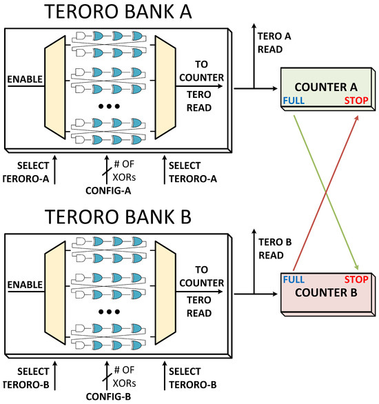
Figure 6.
Proposal of the TERORO-PUF with the possibility of using all methods of evaluation. Note that the output buffers are missing for legibility purposes. The configuration inputs “CONFIG-A" and “CONFIG-B" have as many bits as the number of XOR gates in each PUF.
We are going to define a metric called the “extraction efficiency” as follows:
4.1. RO Count and Compare
In this mode of operation, the TERORO cell is configured with an odd number of inverting stages, thus having an unending oscillation as long as the enable signal is active. The goal in this method of evaluation is to count the number of oscillations of two ROs in parallel and to see which one is faster. This is known by observing which RO fills the binary counter first. From the competition, one bit is extracted, typically called the sign-bit, depending on which RO won the “race”.
In the proposed architecture of Figure 6, the TERORO cells are configured as ROs of the desired inverting stages. Then, the oscillation is enabled for a certain chosen pair of cells, and when one of the counters is full, the challenge is over, the other counter stops counting, and the sign bit is read (which counter triggered the “FULL” flag). To avoid bias in the responses, it is recommendable to always compare a pair with the same configuration.
In this mode of operation, one bit is extracted per pair of cells (), which is half a bit per cell, considering that each cell is used only in one competition, which is recommended to achieve better security against electromagnetic side-channel attacks [10].
4.2. RO Count and Extract from Loser
In [30] the authors designed an evaluation method for RO-PUFs that allows the possibility of extracting more bits per RO pair. Instead of counting oscillations to determine which RO is faster and extracting a sign bit, this method is concerned with the value of the counter of the slower RO. When the faster RO has filled its whole binary counter, the other counter is stopped and some bits are extracted to be used for the PUF response. The idea is to choose the most stable bits (far from the least significant bit) but not too stable that is always the same in all devices (it should have a good uniqueness metric). In [30], the authors found that bits 7 and 8 of a 16-bit binary counter, counting from the Most Significant Bit (MSB), have good reliability and uniqueness. By “good reliability and uniqueness” we refer to uniqueness approaching and reliability along the lines of a mid-to-high range (or higher), depending on whether helper data and error correction are employed.
In the design of Figure 6, the TERORO cells are also configured as RO, but this time, when the challenge is over, the bits are extracted from the counter of the slower RO (the one which did not trigger the “FULL” flag). The selected bits depend on their reliability and uniqueness, which should be calculated for each concrete design.
In this method of operation, two bits are extracted from each pair of cells (), that is, one bit per cell, although it could be more (or less) depending on the uniqueness and reliability metrics of the response of a concrete system. This can be used in parallel with the “RO Count and Compare” method, so that more bits can be extracted in the same run, thus achieving a greater extraction efficiency () combining both methods.
4.3. TERO Collapse Value
When selecting an even number of inverting stages in the TERORO cell, a TERO will be formed and it will oscillate during a certain time and then collapse to either a ‘0’ or a ‘1’. It is required that there is an odd number of inverter stages per branch to achieve an unstable state before activating the enable signal. Also, it is recommended that the branches are configured symmetrically (the inverting stages are in the same position in both branches) so as to not bias the collapse to one of the two branches in particular. In [21], the authors show that symmetrical configurations are more stable and report better results. This final value can be used to extract a bit for the PUF response.
In our proposed architecture, the TERORO cells are configured as a TERO with a certain configuration and then they are enabled and allowed to oscillate for a certain time period until the oscillation is over. Since we do not know when the oscillations are over, after a large enough time is given to let the TERO oscillation collapse, the output “TERO_READ” can be read and stored in a memory component as the final collapsed value of each TERORO cell. In this case, two evaluations can be carried out in parallel, one for each bank of TEROROs.
In this mode of operation, there is one bit extracted per cell ().
4.4. TERO Count and Subtract (or Extract from Loser)
In [13], the TERO-PUF presented uses this mode of operation. They select one pair of TERO and count the total oscillations in each one, then they subtract the values of each counter and extract from one to three stable bits for the PUF response; (in [31], the authors use two to four possible stable bits). In [21], the authors compare the counter mode of operation versus the collapse one. They see that the counter evaluation method has a lower bit-aliasing than the collapse method.
There is also the possibility of choosing some bits of one of the counters of the TERO. In our case we found better results when choosing the bits of the “loser” TERO than when choosing bits from the subtraction result. Although the subtract method is more reliable when temperature variations are present, since the number of oscillations of the TERO would change, the difference between them could give us a more stable response.
For this method, the TERORO cells are also configured as the TERO of chosen stages, but these time bits are extracted from the value of the counter of the “loser” TERO after the oscillation of the selected TERO pair is finished. As in method “RO Count and Extract from Loser”, the selected bits depend on their reliability and uniqueness. This method can be evaluated in parallel with the “TERO Collapse Value” method. Note that the counters are sufficiently large so that they will never be filled by the temporal oscillations of TERO, they will only be filled when the cells are configured as RO.
In this mode of operation, there are from 1 to 4 bits extracted per pair of cells, that is, from 0.5 to 2 bits per cell. This will depend on the reliability and uniqueness of the counter bits. In our case, to ensure an acceptable reliability, we chose 1 bit per pair of cells, so .
4.5. TERO Count and Compare
We realised that by comparing the counters of a pair of TERORO cells configured as TERO and seeing which one of them has a higher value, that is, which cell had a longer oscillation, we can extract another bit of information for the PUF. It is similar to the “RO count and compare” method, but in this case, it is not the “fastest” oscillator the one who determines the output bit, but the most “enduring” one. We can also call this the sign-bit. This method can also be evaluated in parallel with the other two TERO methods.
Like in method “RO Count and Compare”, half a bit per cell is extracted (), also considering that the cells are used only once per competition.
To summarise, in Figure 7 we can see the comparison between all the TERORO modes of operation and their extraction efficiency.
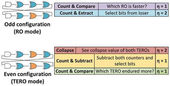
Figure 7.
Comparison of all the possible TERORO modes of operation.
4.6. Alternative Evaluation—Hybrid Mode
There is a possible alternative hybrid configuration that can be used to achieve greater security against ML attacks if the TERORO-PUF is implemented as a strong PUF, or against side-channel in any case. The idea is to first evaluate all the TERORO cells as a TERO of a certain configuration, depending on the input challenge, and use the collapse value as an extra internal configuration parameter.
For example, suppose that a strong TERORO-PUF of 8 TERORO cells per bank (see Figure 8) is implemented. When the challenge is sent, all 16 TERORO cells are evaluated as TERO and the collapsed value of one of the branches is used (if the input challenge is odd, that is, it configures a RO, it should be processed to adjust to a TERO configuration). Suppose that, for reliability purposes, an error correction is performed [29] and the 16-bit raw unstable output is reduced to an 8-bit stable output. This intermediate response, which should be different for each device, can be used to mask the input challenge for the subsequent TERORO configuration, either TERO or RO. Basically, we are using the same PUF to generate an intermediate response that will be used to break the dependence between the challenge and the response. This is up to the designer and will depend on the reliability of the TERO evaluation (maybe the error correction needs to be more aggressive, reporting a smaller intermediate configuration bit-string).
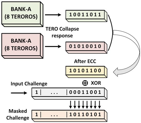
Figure 8.
Example of the Hybrid Method for masking an input challenge.
It is important to reserve a ‘parity bit’, for example, the first one, to ensure that the resulting challenge after the masking operation has the same parity as the original input challenge. For RO configurations the parity is odd, and for TERO configurations the parity is even. In the TERO case the parity check must be carried out in both branches because, as we have stated earlier, each branch must have an odd number of inverting stages to ensure an unstable state before setting the enable signal. Same with the masking operation, it should be carried out in both branches so that they remain symmetrical.
Note that in this example we have used the “TERO Collapse Value” method for generating the intermediate response, but any method could be used, or even several or all of them combined, if we want more layers of masking.
Note, also, that the masking operation could be carried out in the PUF output as well, masking the response instead of the challenge. The intermediate response could even be used to select the mode of operation that will be used to generate the PUF response. In these cases no parity bit would be necessary.
We see that having the extra configurability of TERO and RO gives us a wide range of possibilities, both in the options of the intermediate response and in the target of the masking operation.
5. Results in FPGA Test Implementation
In order to test the behaviour of the proposed TERORO cells, we are going to carry out an implementation on an Artix-7 FPGA. This will be a strong PUF with few TERORO cells (only one per bank) with many gates per cell, thus yielding many combinations of CRPs.
The circuit consists of two 32-stage TERORO cells, each one connected to a 16-bit binary counter with the proper auxiliary circuitry to control the whole system and to receive and transmit data. With that many stages, the total number of configurations is for the TERO mode (considering symmetrical configurations and odd parity in each branch) and for the RO mode (considering asymmetrical configurations and odd parity). With that many configurations, as few as two TERORO cells can be used to generate a long enough output. In Figure 9 we can see a simplified schematic of the implemented circuit. Since there is only one TERORO per bank, no selectors are needed and the output of each cell is connected directly to each corresponding counter. The configuration for cell A is the same for cell B.
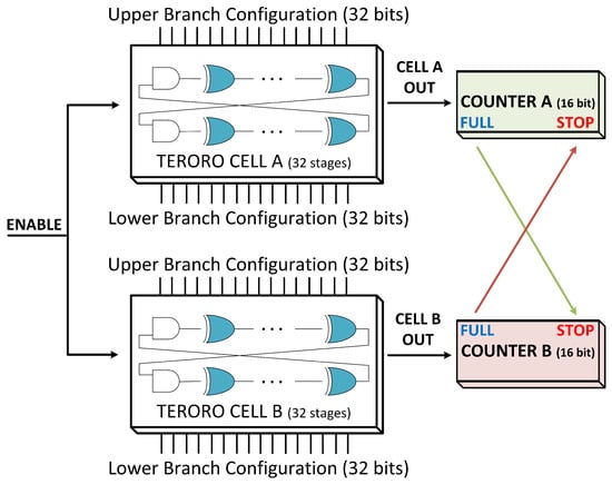
Figure 9.
Schematic of FPGA implementation of the strong TERORO-PUF.
The evaluation test is performed as follows:
- 1.
- Send the configuration bit-string for TERO and RO. The number of configurations is (a random subset of all challenges), and each one is evaluated 10 times.
- 2.
- Receive the contents of both counters and the collapse value of the signal, in the case of the TERO configuration, and the sign bit.
- 3.
- Store the data on MATLAB R2022b and perform the necessary operations to characterise the PUF according to the metrics shown in Section 3.
- 4.
- Repeat the operation across the 16 test devices (Artix-7 FPGAs) for inter-device comparison, and repeat on single devices for intra-device comparison.
Figure 10 illustrates the experimental workflow as follows: configuration is sent from the host to the FPGA, the selected mode is evaluated, raw signals (counters/collapse/sign) are read back, and metrics are computed offline.
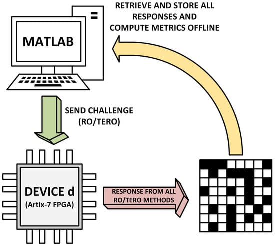
Figure 10.
Experimental workflow of the evaluation test.
5.1. RO Results: Counter Bits and Sign Bit
We now present the results of the experimental evaluation of the implemented TERORO-PUF. Note that bit-aliasing is not shown because, in this case, since we are calculating the average of the parameters, the average bit-aliasing across all configurations is the same as the average uniformity across all devices. In the case of reliability and stability, we show the result for a particular device across 300 samples for each of the 8192 configurations for time-saving reasons. Uniformity is represented as F, uniqueness as U, reliability as X, and stability above as S.
In Table 1, we can see the average uniformity of the bits on the 16-bit counter of the slowest RO. The most significant counter bits can appear saturated due to the stopping criterion (one counter reaching FULL), making those bits nearly constant across configurations; this can yield extreme values (e.g., uniformity near while providing negligible uniqueness), and therefore, these MSBs are not suitable candidates for response extraction.

Table 1.
Average uniformity, uniqueness, and reliability of the bits of the loser counter for the RO configuration. The bits are counted from the MSB.
By selecting the most uniform, unique and reliable bits, bits 9 and 10, the 8192 × 2 = 16,384-bit output response of the PUF is shown in Figure 11 for one particular device. Black pixels represent a stable ‘0’ and white ones a stable ‘1’. The pixels with colour represent unstable bits, and the colour depends on their “closeness” to a stable ‘1’ (yellow) or ‘0’ (dark red). The uniformity (considering only the stable bits) is and the percentage of bits with a reliability higher than is .
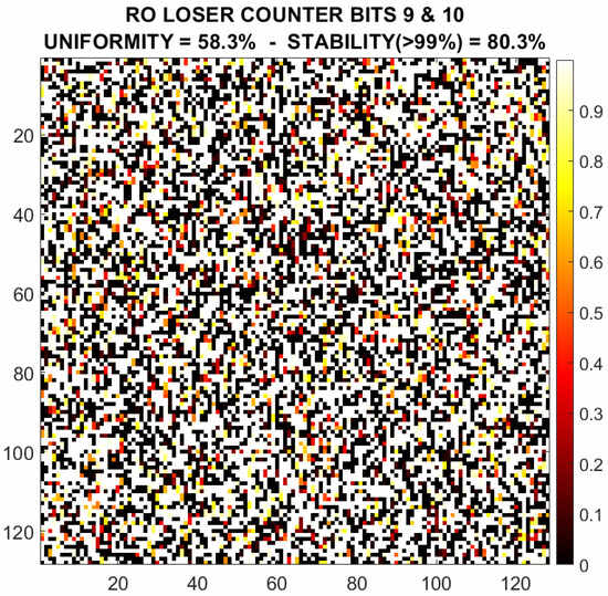
Figure 11.
Example of the response of the RO loser counter selected bits (9 and 10) for device #1.
In Figure 12 there is a histogram of the uniformity and uniqueness for the output generated by bits 9 and 10 for the RO configuration across all the 16 test devices. We can see that bit 10 is more centred around the mean (∼50%) distribution while bit 9 has a broader distribution. This gives a slight disadvantage to the quality of the characteristics of bit 9, but it is compensated by a better reliability ( vs. , see Table 1).
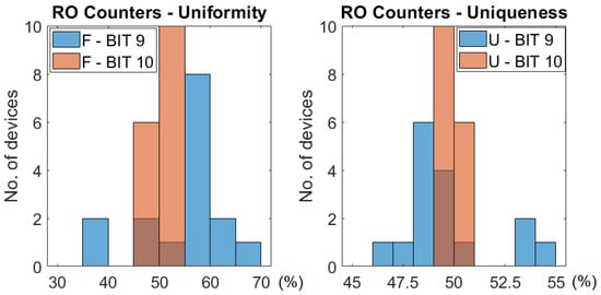
Figure 12.
Distribution of the uniformity and uniqueness across all 16 devices for bits 9 and 10 of the counters for RO configuration.
In the case of the sign bit, for the RO configuration, the second cell was faster in all evaluations. This shows that the frequency of the TERORO cell in RO mode depends little on the configuration.
5.2. TERO Results: Counter Bits, Collapse Value, and Sign Bit
Table 2 shows the average uniformity of the bits of the counter of the TERO that had a shorter oscillation (the “loser” one).
Table 2.
Average uniformity and reliability of the bits of the loser counter for TERO configuration. The bits are counted from the MSB.
Bit 10 could be used to generate an output. The result is shown in Figure 13 for one particular device. The uniformity is and the percentage of stable bits with a reliability of or more is . As we see, comparing with the response of the RO configuration, this response is less stable. Nevertheless, with an algorithm of selection and error correction we could select only those configurations that produce a stable output and discard the unstable ones. This would reduce the bit-length of the output (or the usable CRPs), but it will produce a stable and usable response.
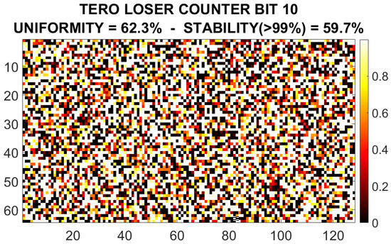
Figure 13.
Example of the response of the TERO loser counter selected bit (9) for device #1.
In Figure 14 there is a histogram of the uniformity and uniqueness across all the test devices for the output generated by bits 9 and 10 for the TERO configuration. We see that bit 9 has a worse quality in terms of uniformity and uniqueness, although it has a better reliability and stability, so it could be considered as a candidate for the response in the TERO count and extract from loser mode. In Table 2 we see that bit 11 has good uniformity and uniqueness metrics, but reliability and stability are lower (less than half of the bits are stable in this case), so the decision of using it as part of the response must be pondered depending on whether we want a more reliable PUF or a more uniform and unique one. In Section 6 we see that bit 11 also has a higher instability for extreme temperatures (in the −10 °C to 80 °C range) than bits 9 and 10.
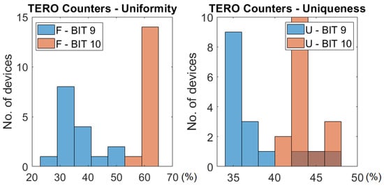
Figure 14.
Distribution of the uniformity and uniqueness across all 16 devices for bits 9 and 10 of the counters for the TERO configuration.
Table 3 shows the uniformity and reliability of the sign bit, the value of the collapsed signal of the TEROROs, the XOR operation of the collapse value of both cells, and the XOR operation of both the collapse value and the sign bit together, respectively. This last metric can be seen as strange, but the reason we have computed it is because the results are not that good in terms of uniqueness on the other metrics independently, but when XORed, they give a much better result in terms of uniformity and uniqueness. The reliability is lower ( reliability, and of stability), but it is still a viable result.
Table 3.
Average uniformity, uniqueness, and reliability of the bits of several values for the TERO configuration.
By looking at the uniformity of the “XOR collapse” value, which is the XOR operation of the collapse signal of cell A and cell B, we can infer that the collapse value of cell A is often the same as the one of cell B. Also, the uniqueness of the collapse signal is low, showing us that there is a bias in the structure that favours one particular state over the other. This is probably because of an asymmetric routing in the FPGA, where a bias is introduced in some gates so that some configurations give us a very similar response in all devices. We did not see this behaviour in the counter or sign modes, because there only the number of oscillations matters, and whether the oscillation collapses to a ‘0’ or a ‘1’ is irrelevant and is not affected by this bias.
6. Thermal Characterisation
In this Section, we assess the stability of the response when changing the temperature of the FPGA from −10 °C to 80 °C in device #1, the same one we used to compute the reliability and stability for nominal operating conditions, which we have called the “model response”. We will compute the difference between the response in a certain temperature and the model response considering only those configurations that are already stable at nominal temperature. The difference is computed using the HD expressed in percentage. We will divide the analysis in two categories as follows: the “counter responses”, which are those that use the bits of the loser counter, for either RO mode or TERO mode, and the response for the collapse bit of each cell, the sign bit, and the XOR of all.
From Figure 15 and Figure 16 we can infer that the nominal temperature is between 20 °C and 40 °C, although, interestingly enough, in the RO counter response, the bits are more stable in the 40 °C and 50 °C range.
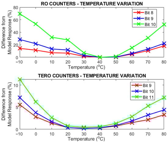
Figure 15.
Difference from the model response in device #1 of the counter response (RO & TERO) across the selected temperature range [−10 °C, 80 °C] in 10 °C steps.
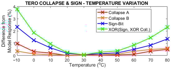
Figure 16.
Difference from the model response in device #1 of the collapse bit of each cell, sign bit, and the XOR operation of all across the selected temperature range [−10 °C, 80 °C] in 10 °C steps.
Concerning the counter response, in Figure 15, we see that bits 8, 9, and 10 of the RO mode have a higher instability for extreme temperatures compared to bits 9, 10, and 11 of the TERO response. For bit 10 there is as high as a 70% difference from the model response at −10 °C, which means that more than half of the stable bits of the response were “flipped”. Although in Section 5 we used bit 10 to generate a response, we see that it is more unreliable than bits 8 and 9. Nevertheless, we see that between 40 °C and 50 °C the response has a low difference for all three bits, so the selection for the response will depend on the environmental conditions. In the case of the TERO mode, the difference is lower, having a high stability plateau at the [20 °C, 40 °C] range and a higher variation at the extreme temperatures, particularly the cold ones, but it is not as high as the RO mode response.
In Figure 16 we see that the collapse bits of both cells are the most stable response across all temperatures, with not even a 1% difference from the model response. The sign bit is slightly more unstable in the extremes and the XOR of all values is the one with a greater difference from the model response. Nevertheless, all of them have a lower variation that the ones of the counter response.
This behaviour was expected, particularly for the RO mode, because the frequency of oscillation of ROs is very dependent on temperature. In the case of the TERO counter mode, the instability is lower than in the RO mode because the important metric here is not the “speed” of the oscillator, that is, the frequency, but the “endurance”, that is, the number of oscillations until collapse. Both branches of the TERO can be considered as two ROs connected to each other, so the number of oscillations depends more on the difference of the delays of both branches (the difference of the frequencies of both ROs). Then, if temperature changes, both ROs will be affected and this change will be cancelled when coupled together in the TERO.
7. Comparison of the Results
In this section we compare the results of the characterisation metrics of the TERORO-PUF with other TERO-PUFs and RO-PUFs in the scientific literature. To put RO/TERO-like designs in context, Table 4 provides a high-level qualitative comparison of representative strong PUF families (e.g., Arbiter-based, XOR Arbiter, Feed-Forward, SRAM-based, Bistable Ring, and RO/TERO-based designs). The goal is not to rank schemes by a single metric, but to summarise the main advantages and drawbacks of each type of PUF.
Table 4.
Qualitative comparison between types of strong PUFs.
In Table 5 there is a comparison of the uniformity, uniqueness, and reliability of the different methods of evaluation compared with other similar PUFs. In the case of the methods that involve the bits of the counters, we used bit 9 for RO mode and bit 10 for TERO mode.
Table 5.
Comparison of the characteristics of the TERORO-PUF with other ROs and TERO PUFs.
Cross-paper comparisons should be interpreted with care, as reported metrics depend on the FPGA family, the number of devices, environmental conditions (temperature/voltage), CRP selection methodology, and whether auxiliary circuitry is included in the reported area (for results in Table 6).
Table 6.
Comparison of the resources used and total CRPs of the TERORO-PUF with other PUFs.
In RO mode, the TERORO-PUF achieves uniqueness, which is close to the values reported by several RO-based strong PUFs. Uniformity () and reliability () are within the range of prior studies, although some designs report uniformity closer to the ideal and slightly higher reliability. Overall, these results indicate competitive RO mode behaviour while prioritising configurability and compact FPGA cost.
In the case of the TERO counter mode, we have a uniformity of , a uniqueness of , and a reliability of . These results are improvable and worse than the other TERO PUFs in the table, but we have better results for the XOR operation of the collapse value and the sign bit (which we have called “TERO XOR” in Table 5 and placed it in the last row). In this case, we have a uniformity of , which is better than most of the other sign and collapse results of the other TERO-PUFs. The uniqueness is , improvable but close to the other PUFs, and the reliability is , which in this case is the weakest point.
Performance can be further improved by (a) bit-position selection based on joint reliability/uniqueness screening, (b) challenge screening to discard unstable configurations, and (c) lightweight post-processing/ECC when stable key material is required. In addition, enforcing a tighter placement/routing symmetry may reduce the structural bias observed in collapse-based metrics, while mixed outputs (e.g., XOR combinations) can mitigate bias at the response level (as observed).
In Table 6 there is a comparison in terms of the occupied resources of FPGA. The most important metrics are the last two, which state the amount of LUTs per bit of the challenge input. This shows how much does LUT utilisation escalates in proportion to the length of the challenge bit-string. The lower it is, the more compact the PUF will be for a certain amount of maximum CRPs. We must say that this metric should only be applied to strong PUFs, because weak PUFs have a low amount of CRPs by construction.
By looking at the implementation costs, we see that the TERORO-PUF is quite compact compared to other implementations. With only 142 LUTs and 36 registers in 82 slices, we can implement a strong PUF with almost CRPs for RO mode and CRPs for TERO mode. This gives us 2.25 LUTs per bit of the configuration input for the RO mode and 4.58 LUTs per bit for the TERO mode. The important comparisons should be carried out with the same type of strong PUFs of several stages, like the configurable RO-PUFs in [18,19] or the configurable TERO-PUFs in [21,23]. The design presented in [26] which also has the RO and TERO modes in the same structure is an important comparison.
The RO-PUF in [18] is the only one that surpasses the TERORO-PUF with 1.13 LUTs/bit, although this is without considering the extra circuitry like counters, only the ROs (in this design they use one reference RO and another target RO). Even so, for long challenges like in this case, the contribution in terms of the hardware utilisation of the other circuitry is not that significant. This design uses four configuration bits and two LUTs per inverting stage, while we use one configuration bit and one LUT per inverting stage, half the amount of configuration bits per LUT. That is why the TERORO has an almost double amount of LUTs per configuration bit. The RO-PUF in [19] uses 6.56 LUTs/bit.
The TERO-PUF in [21] achieves an even better result with only 0.5 LUTs per configuration bit, because it uses five configuration bits and only 1 LUT per stage. Nevertheless, in this paper, the authors did not show any results regarding hardware utilisation, although we inferred from their design how many LUTs they would require to achieve a TERO-PUF with a similar amount of CRPs. Also, the TERO PUF in [23] uses approximately half of the LUTs/bits of configuration (2.03) that we use because it only uses one TERO and we use two for this TERORO implementation.
The PUF in [26] is the only one we found that has both TERO and RO capabilities (although they only use the collapse value for the TERO configuration) in the same PUF, and it uses a total of 110 LUTs to implement a PUF with 16-bit challenges for both RO and TERO mode. Nevertheless, this design uses a feedback obfuscation mechanism for the challenges; considering only the oscillator core, they use the same LUTs as bits of configuration plus one, which would give a result of almost 1 LUT/bit.
The results, although improvable, show that they can be used in a real-world application with some error correction and post-processing algorithms. The better results we obtained were from the RO mode, although the TERO modes are also usable. In this particular implementation the RO sign-bit is not used, but it could be interesting to compare the values of the counters of one single TERORO cell in RO mode across two different configurations with another reference clock signal (system clock or another reference RO). The area used is quite compact, similar to other strong PUFs in the literature, and it could be improved by using all the inputs in the LUTs as configuration bits as stated earlier to achieve a greater amount of CRPs per LUT. The main advantage of this design is its flexibility and multiple mode of operation that allows obfuscation using an intermediate result (see Section 4) or just as a way of having extra responses per challenge.
8. Conclusions
We have presented in this paper a full assessment of an FPGA implementation of a PUF that implements the RO and TERO functionalities in the same cell, the so-called TERORO cell. The main strength of the TERORO-PUF is that it is quite compact in terms of area and resource utilisation and it has the capability of retrieving several responses from two different functionalities, RO and TERO.
The proposed TERORO-PUF provides near-ideal uniqueness in RO-counter extraction () with reliability. In TERO configuration, XOR-based mixing improves the balance of uniformity/uniqueness (/) at the cost of reduced reliability (), motivating response-bit screening and lightweight post-processing in future work. In terms of resource utilisation, it maintains a compact implementation (142 LUTs/36 registers/82 slices).
The sign bit of the RO configuration retrieved always the same response, so it could not be used, but a different implementation with more TERORO cells, or comparisons with the same cell but different challenges plus a reference clock or RO, could be interesting as future work to be able to exploit the sign-bit of the RO mode.
Author Contributions
Conceptualisation, J.N. and A.C.-G.; methodology, A.C.-G. and J.N.; software, A.C.-G.; investigation, J.N.; writing—original draft preparation, A.C.-G.; writing—review and editing, A.J.A., J.N., E.T.-S., and F.E.P.-O.; supervision, E.T.-S. and F.E.P.-O.; project administration, A.J.A. and E.T.-S.; funding acquisition, E.T.-S. and A.J.A. All authors have read and agreed to the published version of the manuscript.
Funding
This paper has been funded by grant USECHIP (TSI-069100-2023-001), project funded by the Secretary of State for Telecommunications and Digital Infrastructure, Ministry for Digital Transformation and Civil Service and by the European Union NextGenerationEU/PRTR. The authors also want to thank project GreenCrypt Grant PID2024-158044OB-I00 funded by MICIU/AEI/10.13039/501100011033.
Data Availability Statement
The raw data supporting the conclusions of this article will be made available by the authors on request.
Conflicts of Interest
The authors declare no conflicts of interest. The funders had no role in the design of the study; in the collection, analyses, or interpretation of data; in the writing of the manuscript; or in the decision to publish the results.
References
- Raeisi-Varzaneh, M.; Dakkak, O.; Alaidaros, H.; Avci, İ. Internet of things: Security, issues, threats, and assessment of different cryptographic technologies. J. Commun. 2024, 19, 78–89. [Google Scholar] [CrossRef]
- Kietzmann, P.; Schmidt, T.C.; Wählisch, M. PUF for the commons: Enhancing embedded security on the OS level. IEEE Trans. Dependable Secur. Comput. 2023, 21, 2194–2210. [Google Scholar] [CrossRef]
- Shamsoshoara, A.; Korenda, A.; Afghah, F.; Zeadally, S. A survey on Physical Inclonable Function (PUF)-based security solutions for Internet of Things. Comput. Netw. 2020, 183, 107593. [Google Scholar] [CrossRef]
- Al-Meer, A.; Al-Kuwari, S. Physical Unclonable Functions (PUF) for IoT devices. ACM Comput. Surv. 2023, 55, 1–31. [Google Scholar] [CrossRef]
- Pappu, R.; Recht, B.; Taylor, J.; Gershenfeld, N. Physical One-Way Functions. Science 2002, 297, 2026–2030. [Google Scholar] [CrossRef]
- Gołofit, K. Security primitives for memoryless IoT devices based on Physical Unclonable Functions and True Random Number Generators. Sci. Rep. 2024, 14, 24060. [Google Scholar] [CrossRef] [PubMed]
- McGrath, T.; Bagci, I.E.; Wang, Z.M.; Roedig, U.; Young, R.J. A PUF Taxonomy. Appl. Phys. Rev. 2019, 6, 011303. [Google Scholar] [CrossRef]
- Schinianakis, D. Lightweight security for the Internet of Things: A soft introduction to Physical Unclonable Functions. IEEE Potentials 2019, 38, 21–28. [Google Scholar] [CrossRef]
- Rührmair, U.; Sehnke, F.; Sölter, J.; Dror, G.; Devadas, S.; Schmidhuber, J. Modeling attacks on Physical Unclonable Functions. In Proceedings of the 17th ACM Conference on Computer and Communications Security; Association for Computing Machinery: New York, NY, USA, 2010; pp. 237–249. [Google Scholar]
- Merli, D. Attacking and protecting Ring Oscillator Physical Unclonable Functions and Code-Offset Fuzzy Extractors. Ph.D. Thesis, Technische Universität München, München, Germany, 2014. [Google Scholar]
- Maiti, A.; Casarona, J.; McHale, L.; Schaumont, P. A large scale characterization of RO-PUF. In 2010 IEEE International Symposium on Hardware-Oriented Security and Trust (HOST); IEEE: Piscataway, NJ, USA, 2010; pp. 94–99. [Google Scholar]
- Cherkaoui, A.; Bossuet, L.; Marchand, C. Design, evaluation, and optimization of Physical Unclonable Functions based on Transient Effect Ring Oscillators. IEEE Trans. Inf. Forensics Secur. 2016, 11, 1291–1305. [Google Scholar] [CrossRef]
- Marchand, C.; Bossuet, L.; Mureddu, U.; Bochard, N.; Cherkaoui, A.; Fischer, V. Implementation and characterization of a Physical Unclonable Function for IoT: A case study with the TERO-PUF. IEEE Trans. Comput.-Aided Des. Integr. Circuits Syst. 2017, 37, 97–109. [Google Scholar] [CrossRef]
- Tebelmann, L.; Pehl, M.; Immler, V. Side-channel Analysis of the TERO PUF. In Proceedings of the Constructive Side-Channel Analysis and Secure Design: 10th International Workshop, COSADE 2019, Darmstadt, Germany, 3–5 April 2019; Proceedings 10. Springer: Berlin/Heidelberg, Germany, 2019; pp. 43–60. [Google Scholar]
- Mureddu, U.; Colombier, B.; Bochard, N.; Bossuet, L.; Fischer, V. Transient Effect Ring Oscillators Leak Too. In 2019 IEEE Computer Society Annual Symposium on VLSI (ISVLSI); IEEE: Piscataway, NJ, USA, 2019; pp. 37–42. [Google Scholar]
- Osuka, S.; Fujimoto, D.; Kawamura, S.; Hayashi, Y. Electromagnetic Side-Channel Analysis against TERO-based TRNG. IEEE Trans. Electromagn. Compat. 2022, 64, 1288–1295. [Google Scholar] [CrossRef]
- Maiti, A.; Schaumont, P. Improving the quality of a physical unclonable function using configurable ring oscillators. In 2009 International Conference on Field Programmable Logic and Applications; IEEE: Piscataway, NJ, USA, 2009; pp. 703–707. [Google Scholar]
- Hu, Y.; Jiang, Y.; Wang, W. Compact FPGA Ring Oscillator Physical Unclonable Functions Circuits Based on Intertwined Programmable Delay Paths. Preprint 2021. [Google Scholar] [CrossRef]
- Cui, Y.; Li, J.; Chen, Y.; Wang, C.; Gu, C.; O’neill, M.; Liu, W. An efficient Ring Oscillator PUF using programmable delay units on FPGA. ACM Trans. Des. Autom. Electron. Syst. 2023, 29, 1–20. [Google Scholar] [CrossRef]
- Liu, W.; Zhang, L.; Zhang, Z.; Gu, C.; Wang, C.; O’neill, M.; Lombardi, F. XOR-based low-cost reconfigurable PUFs for IoT security. ACM Trans. Embed. Comput. Syst. (TECS) 2019, 18, 1–21. [Google Scholar] [CrossRef]
- Hu, Y.; Jiang, Y.; Wang, W. Transient Effect Ring Oscillator PUF Based on Programmable Delay Lines. In 2022 International Conference on Innovations in Science, Engineering and Technology (ICISET); IEEE: Piscataway, NJ, USA, 2022; pp. 528–533. [Google Scholar]
- Spagnolo, F.; Vatalaro, M.; Perri, S.; Crupi, F.; Corsonello, P. C4TERO: Configurable Cascaded Carry Chains for High Reliability TERO PUFs on FPGAs. IEEE Trans. Circuits Syst. I Regul. Pap. 2024, 72, 561–572. [Google Scholar] [CrossRef]
- Bian, J.; Du, X.; Lu, Y.; Yan, A.; Liang, H.; Huang, Z. A chaotic strong transition effect ring oscillator PUF with effective immunity to modeling attacks. Microelectron. J. 2025, 157, 106592. [Google Scholar] [CrossRef]
- Vicuña, K.; Vatalaro, M.; Amiel, F.; Crupi, F.; Trojman, L. Highly Stable Reconfigurable TERO PUF Architecture for Hardware Security Applications. IEEE Trans. Very Large Scale Integr. (VLSI) Syst. 2025, 33, 2873–2882. [Google Scholar] [CrossRef]
- Casado-Galán, A.; Núñez-Martínez, J.; Tena-Sánchez, E.; Potestad-Ordóñez, F.E.; Acosta, A.J. TERORO—Transient Effect Ring Oscillator and Ring Oscillator Configurable Hybrid PUF. In 21st International Conference on Synthesis, Modeling, Analysis and Simulation Methods, and Applications to Circuit Design (SMACD 2025); IEEE: Piscataway, NJ, USA, 2025. [Google Scholar]
- Li, H.; Cao, W.; Wang, C.; Zhu, X.; Liao, G.; He, Z. FOM-CDS PUF: A Novel Configurable Dual State Strong PUF Based on Feedback Obfuscation Mechanism against Modeling Attacks. IEICE Trans. Fundam. Electron. Commun. Comput. Sci. 2023, 106, 1311–1321. [Google Scholar] [CrossRef]
- Gao, M.; Lai, K.; Qu, G. A highly flexible ring oscillator PUF. In 51st Annual Design Automation Conference; IEEE: Piscataway, NJ, USA, 2014; pp. 1–6. [Google Scholar]
- Maiti, A.; Gunreddy, V.; Schaumont, P. A systematic method to evaluate and compare the performance of Physical Unclonable Functions. In Embedded Systems Design with FPGAs; Springer: New York, NY, USA, 2013; pp. 245–267. [Google Scholar]
- Delvaux, J.; Gu, D.; Schellekens, D.; Verbauwhede, I. Helper data algorithms for PUF-based key generation: Overview and analysis. IEEE Trans. Comput.-Aided Des. Integr. Circuits Syst. 2014, 34, 889–902. [Google Scholar] [CrossRef]
- Kodỳtek, F.; Lórencz, R. A Design of Ring Oscillator based PUF on FPGA. In 2015 IEEE 18th International Symposium on Design and Diagnostics of Electronic Circuits & Systems; IEEE: Piscataway, NJ, USA, 2015; pp. 37–42. [Google Scholar]
- Bossuet, L.; Ngo, X.T.; Cherif, Z.; Fischer, V. A PUF based on a Transient Effect Ring Oscillator and Insensitive to Locking Phenomenon. IEEE Trans. Emerg. Top. Comput. 2013, 2, 30–36. [Google Scholar] [CrossRef]
- Hemavathy, S.; Bhaaskaran, V.K. Arbiter PUF—A review of design, composition, and security aspects. IEEE Access 2023, 11, 33979–34004. [Google Scholar] [CrossRef]
- Sayadi, N.; Nguyen, P.H.; Van Dijk, M.; Jin, C. Breaking XOR Arbiter PUFs with Chosen Challenge Attack. IEEE Trans. Inf. Forensics Secur. 2025, 20, 4971–4984. [Google Scholar] [CrossRef]
- Rührmair, U.; Sölter, J. PUF modeling attacks: An introduction and overview. In 2014 Design, Automation & Test in Europe Conference & Exhibition (DATE); IEEE: Piscataway, NJ, USA, 2014; pp. 1–6. [Google Scholar]
- Rührmair, U.; Sölter, J.; Sehnke, F.; Xu, X.; Mahmoud, A.; Stoyanova, V.; Dror, G.; Schmidhuber, J.; Burleson, W.; Devadas, S. PUF modeling attacks on simulated and silicon data. IEEE Trans. Inf. Forensics Secur. 2013, 8, 1876–1891. [Google Scholar] [CrossRef]
- Baek, S.; Yu, G.H.; Kim, J.; Ngo, C.T.; Eshraghian, J.K.; Hong, J.P. A reconfigurable SRAM based CMOS PUF with challenge to response pairs. IEEE Access 2021, 9, 79947–79960. [Google Scholar] [CrossRef]
- Pham, V.K.; Ngo, C.T.; Nam, J.W.; Hong, J.P. A reconfigurable SRAM CRP PUF with high reliability and randomness. Electronics 2024, 13, 309. [Google Scholar] [CrossRef]
- Santana-Andreo, A.; Saraza-Canflanca, P.; Castro-Lopez, R.; Roca, E.; Fernandez, F. Reliability improvement of SRAM PUFs based on a detailed experimental study into the stochastic effects of aging. AEU-Int. J. Electron. Commun. 2024, 176, 155147. [Google Scholar] [CrossRef]
- Chen, Q.; Csaba, G.; Lugli, P.; Schlichtmann, U.; Rührmair, U. The bistable ring PUF: A new architecture for strong physical unclonable functions. In 2011 IEEE International Symposium on Hardware-Oriented Security and Trust; IEEE: Piscataway, NJ, USA, 2011; pp. 134–141. [Google Scholar]
- He, Z.; Wang, C.; Ke, T.; Zhang, Y.; Cao, W.; Jiang, J. A highly reliable FPGA-based RO PUF with enhanced challenge response pairs resilient to modeling attacks. IEICE Electron. Express 2021, 18, 20210350. [Google Scholar] [CrossRef]
- Martínez-Rodríguez, M.C.; Rojas-Muñoz, L.F.; Camacho-Ruiz, E.; Sánchez-Solano, S.; Brox, P. Efficient RO-PUF for generation of identifiers and keys in resource-constrained embedded systems. Cryptography 2022, 6, 51. [Google Scholar] [CrossRef]


Disclaimer/Publisher’s Note: The statements, opinions and data contained in all publications are solely those of the individual author(s) and contributor(s) and not of MDPI and/or the editor(s). MDPI and/or the editor(s) disclaim responsibility for any injury to people or property resulting from any ideas, methods, instructions or products referred to in the content. |
© 2026 by the authors. Licensee MDPI, Basel, Switzerland. This article is an open access article distributed under the terms and conditions of the Creative Commons Attribution (CC BY) license.