Abstract
When energy harvesting is not feasible or fails to provide sufficient power, the energy buffer of battery-powered Internet of Things (IoT) devices inevitably depletes. The proper disposal and/or replacement of depleted and end-of-life (EoL) batteries is challenging, especially in rural IoT deployments, where human intervention is cumbersome. When batteries are left in nature, they can pose a significant environmental risk, leaking harmful chemicals into the soil. This work proposes a novel contactless battery solution for longevity and recyclability, providing automated battery replacement using a short-range wireless power transfer (WPT) link instead of a direct battery-to-IoT node contact-based connection for powering the IoT device. It facilitates battery recovery at EoL by, e.g., an unmanned vehicle (UV), reducing the need for manual intervention. Unlike complex mechanical solutions or contacts prone to corrosion, a contactless approach enables easy replacement and improves reliability and longevity in harsh environments. A technical challenge is the need for an efficient contactless solution to enable the IoT node to get energy from the battery. This work elaborates an efficient wireless connection between the battery and IoT node, which ensures robustness in harsh environments. In addition, it examines the sustainability aspects of this approach. The WPT system is applied in two IoT node applications: polling-based and interrupt-based systems. The proposed solution achieves a transmitter-to-receiver efficiency of 72% and has an additional environmental impact of 2.34 kgCO2eq. However, its key advantage is the ease of battery replacement, which could significantly reduce the expected long-term environmental impact.
1. Introduction
The mass-scale adoption of Internet of Things (IoT) devices has raised sustainability concerns, especially for those using non-rechargeable batteries. Innovative energy provisioning solutions are needed to align this massive deployment with the Sustainable Development Goals (SDGs). Batteries are often the shortest-lifespan component in an IoT device. They run out of energy, or, especially rechargeables, only last a couple of years [1]. Their production relies on finite sources with high ecological impacts, such as lithium and cobalt, extending their environmental footprint way beyond their limited lifespan. The disposal of batteries contributes to a growing e-waste problem. Most IoT devices employ a ‘fire-and-forget’ approach [2], where batteries end up in nature and harmful chemicals can leak into soil and groundwater. Properly disposing of and/or replacing depleted and end-of-life (EoL) batteries is challenging, especially in rural IoT deployments, where human intervention is cumbersome [3]. Examples include IoT nodes placed in remote areas such as on mountains and in deserts, agricultural fields, forests, or wetlands, where reaching a single device may require hours of travel across difficult terrain. In some cases, these deployments are located in hazardous or restricted zones (e.g., near wildlife, in wetlands, or in harsh climates), making human access undesirable or even unsafe. Efforts to address these sustainability issues, such as lowering the device’s energy usage [2], only offer temporary solutions since eventually the batteries deplete. Energy harvesting, such as through solar, movement, or radio-frequency (RF) waves, can be used to recharge the device’s energy buffer [4], but often yields insufficient amounts of energy to power a wide range of IoT devices. Even rechargeable batteries face limitations due to their limited charge cycles and performance degradation over time.
This work rethinks the ‘fire-and-forget’ approach, where devices are discarded upon battery depletion, by designing a contactless battery solution for longevity. This design makes battery replacement more feasible, leading to an extended operational lifetime of IoT nodes. An overview of the system is depicted in Figure 1. The system simplifies automated battery replacement using a short-range wireless power transfer (WPT) link instead of a direct battery-to-IoT node contact-based connection, addressing challenges associated with the energy provisioning and EoL recovery of IoT node batteries. The novel energy supply and replacement solution is particularly suited for devices that have encountered a total failure, to recuperate the toxic battery, and in use cases where traditional energy harvesting methods are either ineffective or impractical. Unlike using direct contacts, the wireless design can be fully shielded from the elements, resulting in a durable and reliable system. This can enable use in corrosive environments, underwater applications, or automated unmanned aerial vehicle (UAV)-based applications. This work focuses in particular on the UAV scenario.
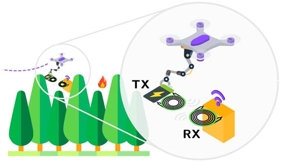
Figure 1.
Overview of the developed system: A contactless battery solution for longevity and recyclability, providing automated battery replacement using a short-range WPT link instead of a direct battery-to-IoT node contact-based connection for powering the IoT device.
Current approaches to precise outdoor localization of IoT nodes rely on real-time kinematics (RTK), the Global Positioning System (GPS), achieving centimeter-level accuracy, or vision-based systems [5,6]. Novel LF antenna-based localization methods have also been proposed, achieving sub-meter accuracy even in GNSS-denied environments [7]. However, challenges remain in scenarios with dense vegetation, and further research is required to enable robust localization even when nodes deviate from their planned deployment. In an indoor environment, acoustic-based systems can provide decimeter-level accuracy [8]. We do not discuss UAV positioning strategies or propose new methods in this manuscript, as the primary focus of this work is on the WPT approach and the sustainability assessment.
The recent State Of The Art (SOTA) has explored long-range energy transfer from UAVs to IoT devices using RF WPT [9,10,11]. However, this method is only practical for extremely low-power IoT systems, since the efficiency of RF WPT decreases significantly over large distances, limiting the amount of transferable energy. The swapping of the UAV battery itself has been explored, where mostly robotic designs are proposed for automatic swapping [12,13]. Limited attention, however, has been given to sustainable battery recovery solutions for IoT nodes. Ref. [14] compared UAV-based WPT recharging with automated battery swapping, using an unmanned vehicle (UV) to bring energy to IoT nodes [14]. It was concluded that battery swapping significantly reduces UAV energy consumption as it eliminates the need for the UAV to hover during battery recharging [14]. Replacing a battery is a complex mechanical operation (especially for a UAV) involving disconnecting contacts. These contacts must be properly shielded from environmental influences causing corrosion. Building on this concept, we propose a novel WPT approach and tailored circuit. The advantages of an easily swappable battery approach are twofold:
- It can supply energy to remote, energy-constrained IoT devices, even those with high energy demands.
- It enables battery recovery and recycling at EoL, preventing harmful components from being left in nature.
The primary challenge lies in maximizing the efficiency of the WPT link between the battery module and the electronics of the IoT node it needs to service for the solution to be feasible and sustainable. Our solution has been optimized to this end, achieving a transmitter-to-receiver efficiency of 72%. The design is shared in open source on GitHub (v1) [15].
The remainder of this paper is structured as follows. Section 2 introduces the novel concept and provides a high-level overview of the system. Section 3 focuses on the design of the contactless battery energy supply and recovery solution itself. Section 4 discusses the validation and performance assessment. Section 5 discusses the sustainability assessment of this solution. Finally, conclusions and future directions are outlined in Section 6.
2. Battery Swapping Approach: High-Level Architecture
This work presents a modular system for powering energy-constrained edge devices by replacing the typical battery-to-IoT node connection with a short-range WPT link within the IoT module to supply the circuits. Please note that, contrary to many WPT methods reported to charge a battery, we here solve the problem of providing the charge in the battery to the IoT node for its operation. Unlike a direct connection, the WPT link simplifies automatic maintenance by UAVs and allows the design to be fully protected from the environment. The swappable battery side operates as a separate, replaceable module and serves as the WPT transmitter. It delivers energy to the IoT node, which acts as the WPT receiver. In addition to energy transfer, a communication link is established between the WPT transmitter (battery side) and the WPT receiver (IoT-node side). Details on how the data is modulated over the WPT link are provided in Section 3.
Two typical IoT application scenarios can be distinguished, polling-based and interrupt-based applications, which correspond to two distinct design implications at the IoT-node side.
- In polling-based applications the sensors’ power can be interrupted, allowing the IoT node to work without a local energy buffer. A potential application of this configuration is in air-quality monitoring, where mostly periodic measurements are required [16].
- Interrupt-based applications require sensors to stay powered. To handle the continuous and unpredictable energy demands of the system, a smaller receiver-side energy buffer is needed. A typical application is sound monitoring, where interrupt-based threshold detection is commonly required to detect short-duration sound spikes [17].
Figure 2 depicts the data flow for both configurations and is divided into three phases: a discovery phase, an energy transfer phase, and a termination phase.
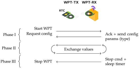
Figure 2.
Data flow of the WPT swappable battery system in three phases: discovery (phase I), energy transfer (phase II), and termination (phase III).
- Phase I (discovery): Communication is always initiated by the transmitter. If the receiver’s energy buffer is depleted, the transmitter first provides enough power to restore functionality and prevents the receiver from remaining discharged. Also, the ability to initiate communication from the receiver side would require additional components. A timer, by the use of a real-time clock (RTC), is kept at the transmitter, enabling and disabling the WPT circuit when energy is needed. A configuration request to the IoT node determines the application-specific WPT parameters. The IoT node stores the application parameters, i.e., type of application, time between measurements, and desired charge current, etc., in non-volatile memory.
- Phase II (energy transfer): After the discovery phase, the energy is transferred to the receiving IoT node. For polling-based operation, the receiving node directly uses the provided power to perform a functional operation, such as taking a measurement. For an interrupt-based system, the provided power is used to charge an energy buffer at the receiving side. The transmitter can be reused for both configurations, while the receiver will be different based on the type of configuration. At this stage, the energy transfer can be optimized by changing the transmitter’s amplitude to obtain an optimal load at the receiver.
- Phase III (termination): The IoT node signals when a measurement is completed, transfers the sleep time, and the system returns to a low-power mode until the next energy transfer. The battery transmitter includes an RTC for timekeeping and periodically enables the WPT link based on the sleep timer value it received. For polling-based operation, the timer value is fixed and periodic, and it is stored in non-volatile memory. A temporary polling interval change can be achieved, provided an update signal in downlink wireless communication can modify the sleep time variable at the IoT-node side. The required sleep time is transferred to the WPT transmitter after each measurement, which in turn changes the wake-up time for the next cycle. In the case of an interrupt-based system, the IoT node dynamically adjusts the sleep time of the transmitter with each charging cycle to keep the energy buffer sufficiently charged at the receiving side. This is done by carefully predicting when the charge of the energy buffer (in a worst-case scenario) will be empty, and therefore notifying the battery of this by changing the RTC timer compare value.
The next section covers an actual design conceived and implemented for the system to enable measurement of key parameters. The focus of this work is mainly on the interrupt-based approach.
3. WPT Design
3.1. Overview of WPT
The goal is to maximize the WPT efficiency, as this directly impacts the battery size or the number of replacement needs. The associated sustainability impacts are discussed in Section 5. Figure 3 gives an overview of the WPT design. This work mostly focuses on interrupt-based systems, which are the more complex of the two. While the hardware on the transmitter side remains unchanged, the receiver side requires an additional energy buffer to ensure uninterrupted operation. For the proposed use cases, the coils remain stationary once installed and are closely aligned, resulting in a fixed and high coupling factor. Normally-on electromagnets, although not included in this prototype, can be used as a low-power option to secure the battery to the IoT node, since this only requires energy when releasing [18].
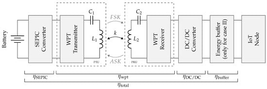
Figure 3.
Overview of the WPT system.
Table 1 summarizes the WPT design specifications. A set of coils was chosen because of their small size (low material needs and compact implementation) and high Q factor. The TX coil (760308101104) has an inductance of 6.8 μH, a Q-factor of 42, a diameter of 2.05 cm, and can handle 2.5 A of current. The RX coil (760308105214) has an inductance of 6.3 μH, a Q-factor of 15, a diameter of 1.9 cm, and can handle 1.5 A of current. Their small form factor makes them suitable for a small and lightweight design. Measurements in Table 2 show that a coupling factor of k = 0.53 is achievable. This provides enough space to fully enclose the system and keeps the coils close enough together for high efficiency. We assume this coupling factor for the remainder of this work. At a distance of 0 mm, the coupling factor is 0.82, at a distance of 5 mm, it is 0.35. The WPT operates at a frequency of 360 kHz, aligning with the Wireless Power Consortium Qi2 standard [19].

Table 1.
Summary of WPT design specifications.
Table 2.
Coupling factor with different distances.
A simple Series–Series (S-S) compensation topology is used for interrupt-based loads, providing good efficiency for a current-like source [20]. In polling-based loads, Series–Parallel (S-P) compensation can ensure efficiency with a higher-impedance receiver and lower current demand. Details on optimal compensation topologies are not the focus of this work and are discussed further in [21]. Communication between the transmitter and receiver is achieved using frequency-shift keying (FSK), while amplitude-shift keying (ASK) is employed for communication from the receiver to the transmitter. ASK is a promising candidate for low-power designs, as it does not require a local oscillator and only modulates the amplitude of the carrier wave [22]. FSK is chosen for transmitter-to-receiver communication to enable full duplex communication. Furthermore, they are commonly used in-band communication methods and align with the Qi standard [23] specifications. As only small amounts of data need to be communicated over the WPT link, the efficiency impact on the WPT link will remain limited. No out-of-band communication is used in this design.
3.2. Swappable Battery as WPT Transmitter
A detailed overview of the WPT transmitter is depicted in Figure 4. The WPT transmitter consists of our own design of a single-cell battery as an energy source, preferably of the lithium iron phosphate (LFP) type with a nominal battery voltage of 3.2 V. LFP is attractive due to its long cycle life, intrinsic safety, and the use of more sustainable and less critical materials compared to other lithium-based chemistries [24,25]. Alternative battery technologies for use at the transmitter side are discussed in Section 5. A battery management and fuel gauge integrated circuit (IC) with low-side current sensing is used as a coulomb counter for power measurements and accurate state of charge (SoC) determination. To achieve a digitally tunable direct current (DC) voltage, a digital potentiometer is used in the feedback loop of a single-ended primary-inductor converter (SEPIC). This regulated voltage feeds into a class D half-bridge converter, which drives the coils with a varying alternating current (AC) signal. A central ARM Cortex M0+ microcontroller unit (MCU) generates the clock signal for the half-bridge, provides intelligent control for the WPT, FSK modulation from transmitter to receiver, and receives the ASK demodulated signals using a Universal Asynchronous Receiver/Transmitter (UART) peripheral. FSK modulation is generated using a combination of two clocks. One clock generates the operating frequency by dynamically switching between 360 kHz and 300 kHz using a compare–match reset. A second clock, with a timing of 1 ms, determines the bit length. By dynamically switching the operating frequency at every compare interrupt of the second timer, an FSK signal is generated. The ASK signals are demodulated using simple passive external components and a comparator with open-drain output. The voltage levels for the transmitter driver circuits and MCU (5 V and 3.3 V) are provided by two low-quiescent current converters, one configured as a boost converter and one configured as a buck–boost converter. A 6.8 μH wire-wound coil with a quality factor of 42 is used as a transmitter coil.
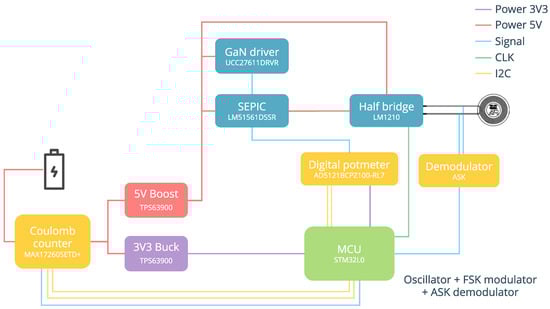
Figure 4.
Overview of the battery-side circuit, acting as WPT transmitter.
3.3. IoT Node Add-On as WPT Receiver
The WPT receiver, illustrated by the schematic in Figure 5, utilizes a 6.3 μH wire-wound coil with a quality factor of 15, followed by a full-bridge rectifier with Schottky diodes. The input power is actively monitored through a dedicated power monitor. A buck/boost converter provides a stable 3.5 V, which is used by a supercapacitor charger with a built-in boost converter. This IC ensures a stable output voltage to the IoT node, even when no input voltage is present. A digital potentiometer adjusts the charge current as needed, charging in constant-current mode most of the time.
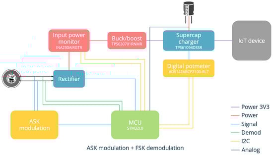
Figure 5.
Overview of the IoT node add-on, acting as WPT receiver.
For this implementation, a supercapacitor with a capacity of 5 F with a charging voltage of up to 3.9 V (charged to 3.5 V) was utilized. It was chosen for its relatively low leakage current of 5 μA. The supercapacitor charging IC starts with a base charge current of 250 mA (below 0.5 V). Once the voltage rises, the charging current increases to the advised value. At the end of the charge cycle, the charge current decreases, finally reaching the charging termination current of 10 mA. As the WPT operates at low efficiencies in the final phase, this phase can be omitted. Alternatively, depending on the capacity requirements, a small lithium titanate (LTO) cell or a Hybrid Layer Capacitor (HLC) [26] can be used as an energy buffer. Alternative energy buffer types and the trade-offs are further discussed in Section 5.
Communication from the receiver to the transmitter is implemented through load modulation. The output signal of a UART peripheral drives two metal-oxide semiconductor field-effect transistors (MOSFETs), which selectively connect or disconnect additional capacitances to detune the receiver’s resonant circuit. This process generates an ASK-modulated signal. A central MCU provides the monitoring, adaptive charging, and bi-directional communication. The receiver performs FSK demodulation using two timers. The first timer detects the varying periods of the incoming signal and detects the start bit. The input frequency is measured from the output of an internal comparator. Upon detection, the second timer, which provides the sampling point for each bit, is enabled and synchronized with the incoming signal. Simultaneously, the first timer is reconfigured as a counter to measure the number of periods in 1-bit period, thereby determining whether the transmitted bit is high or low. Demodulation and modulation can all be done on a simple ARM Cortex M0+ MCU. The communication could be further optimized by integrating custom hardware designed specifically for FSK demodulation.
4. System Validation and Performance Assessment
4.1. Efficiency of WPT Link with Transmitter and Receiver
The WPT link was simulated, prototyped, and experimentally validated. The prototype hardware is shown in Figure 6. It was modeled as realistically as possible, incorporating the Gallium Nitride (GaN) field-effect transistors (FETs), diodes, and measured coil parameters. Measurements were conducted with the same coupling factor for transmitter voltages of 2.5 V and 5 V. The WPT efficiency with varying loads is shown in Figure 7. All measurements were conducted at room temperature. Transmitter measurements were extracted from a PeakTech 6225A DC power supply with a voltage accuracy of ±0.5% + 10 digits and a current accuracy of ±1.5% + 25 digits [27]. Received power measurements were performed with the Korad KEL103 programmable load, with an accuracy of ±0.1% of set value +0.1% offset [28]. Maximal efficiency for an S-S compensation was achieved at equivalent loads between 20 and 100 . A near-optimal load of 55 was experimentally determined. This load prevents the transmitter amplitude from collapsing while still operating in a high-efficiency range. To optimize WPT efficiency, the system needs to operate at its optimal impedance point. As depicted in Figure 8, the equivalent load at the receiver changes from 50 to 1.5 k when charging. These higher equivalent loads impact the achievable efficiency in an S-S compensation topology. An optimal impedance at the receiver can be achieved by the following methods:

Figure 6.
Overview of the developed prototype, suitable for interrupt-based applications. The modular system’s battery side (transmitter, left) operates as a separate replaceable module and delivers energy to the IoT node, which acts as the WPT receiver (right).
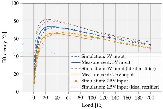
Figure 7.
Efficiency of the WPT link. Full line: measurement; dashed line: simulation; dotted line: simulation with ideal diodes. Driver power consumption is not included.
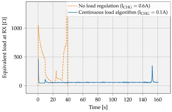
Figure 8.
Equivalent load at the receiver side with and without feedback to transmitter for optimal power transfer. Charge current 0.6 A (no load stabilization) vs. 0.1 A (with continuous load stabilization). Equivalent load at output is stabilized to (in this case) 60 , improving WPT efficiency. With a fixed TX voltage, the equivalent load changes drastically.
- Dynamically changing the amplitude of the transmitter, which changes the amplitude at the receiver. The supercapacitor can then be charged rapidly using a constant current. An example of this approach is given in Figure 8, where the equivalent load at the receiver is set to 60 . The transmitter dynamically adjusts its amplitude with a simple PID controller to match the desired load at the receiver. The equivalent output resistance at the receiver side is calculated based on the on-board INA230 power monitor from TI, with an 0.3% max gain error and 25 V offset [29].
- Charging with constant power, dynamically adjusting its charge current. This simplifies the WPT control mechanisms and keeps the WPT link parameters nearly constant. This is not further implemented in hardware.
Figure 9 depicts the efficiency as a function of received power, assuming a fixed load of 55 . The WPT system can transfer up to 3 W to the receiver with a peak efficiency of 72%. At low power-transfer levels, the diode’s forward voltage drop significantly impacts the WPT efficiency due to low receiver-side voltages. Figure 7 and Figure 9 show the possible theoretical efficiency improvements when an ideal rectifier would be used. For example, at 1 W of delivered power to the receiver, an ideal rectifier improves the efficiency by 9%, with even higher gains at lower output powers. Active rectifier circuits, as demonstrated in recent studies, have the potential to enhance power transfer efficiency [30].
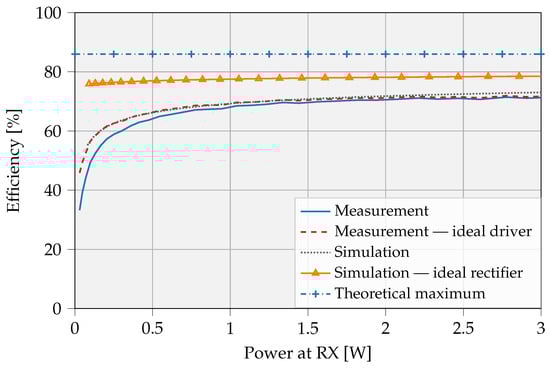
Figure 9.
WPT efficiency with coupling factor k = 0.53 at an RX load of 55 . Peak efficiency = 72%. Driver circuit losses of 25.41 mW are considered in measurement, not in simulation. We show the theoretical maximal efficiency and efficiency improvement using an ideal rectifier.
As typical IoT nodes spend most of their time and total energy budget in sleep mode [2], the design was optimized for low sleep-mode power consumption. The transmitter consumes 5.47 μA at 3.7 V when in sleep mode with a low-power external crystal and an active low-power timer. Using the fuel gauge for tracking the battery SoC, another ±5 μA is added. The receiver consumes 5.44 μA in sleep (STOP) mode with the analog-to-digital converter (ADC) disabled. The ADC can act as a watchdog, monitoring the supercapacitor voltage range and waking the system if the energy source tends to be depleted. When enabled, the average current consumption increases to 16.6 μA.
4.2. Total System Efficiency
The total efficiency is calculated as the product of all sub-efficiencies:
A well-designed SEPIC converter and DC/DC converter can achieve efficiencies of ±90%. The WPT link achieves an efficiency of 72% at receiver powers above 1 W. The used buck converter has an efficiency of 87% at a current consumption of 500 mA converting from 3.6 V to 2 V, while the boost converter reaches efficiencies of 93% converting from 2 V to 3.3 V at 10 mA. Additionally, the charge–discharge efficiency of the supercapacitor is 98% [31]. Substituting typical values, the total system efficiency becomes
Efficiency losses occur mainly in the WPT link. However, when taking into account losses in all converters, the combined converter efficiency drops below that of the WPT link, reaching only 46%. Assuming a similar WPT efficiency can be obtained in the polling-based application, the total efficiency becomes
The polling-based approach offers an efficiency advantage over the interrupt-based approach, as it eliminates the overhead introduced by the additional buffer.
Due to the forward voltage drop of the Schottky diodes used for rectification at the receiver side, part of the energy is dissipated as losses. This is especially prominent when the receiver voltage is low. Replacing the diode-based rectifier with an active rectifier improves efficiency, both at low and high output power levels. At an output power of 3 W, the efficiency increases from 72% to 79%, while at 0.5 W it rises more drastically, from 64% to 77%. The total efficiency increases slightly for interrupt-based systems
and for polling-based systems becomes
4.3. Comparison to Typical Systems
First, we compare our proposed swappable battery system to a typical system directly powered by a lithium-type battery without WPT. A typical system directly operating from a battery would also require a DC/DC converter since the voltage range (3 V to 4.2 V) of lithium-type batteries is not natively supported by most ICs. In this case, the converter’s efficiency is the only factor affecting overall system efficiency and is, as in the previous case, assumed to be 90%.
Second, when comparing our system to a typical energy harvesting system, an energy buffer is also required. Additionally, if automatic replacement of the battery is needed, or the system works with high peak powers, a buffer system would also be necessary. Therefore, for a fair efficiency comparison, the inefficiencies of the SEPIC and WPT can be neglected, while the DC/DC converter and buffer system are still included.
In conclusion, typical energy harvesting solutions achieve a higher overall efficiency of 71% compared to our proposed system. However, they do not provide easy battery replacement, which raises concerns regarding sustainability. The sustainability implications of our design are discussed in the next section.
5. Sustainability Analysis and Discussion
The proposed approach introduces additional hardware and operational requirements. Hence, it is crucial to assess their broader sustainability implications. This section presents a life cycle assessment (LCA) of the proposed design, evaluates alternative energy storage options, both at the transmitter and receiver side, and compares the solution against other approaches, such as contact-based systems and full device replacement, and discusses the use of non-rechargeable batteries. We aim to provide a holistic view of the trade-offs between performance, efficiency, and sustainability by quantifying the environmental impacts.
5.1. Life Cycle Assessment of the Design
Figure 10 depicts the environmental footprint of the additional circuitry needed for the contactless battery prototype solution. The LCA was conducted using Sphera (2025 version) [32], with its built-in database and the extension database XI (Electronics 2024). The Environmental Footprint (EF) 3.1 indicator [33], maintained by the European Commission, was employed for the impact assessment. In this work, we specifically focus on the Global Warming Potential (GWP) over 100 years, using the ‘Climate Change’ indicator, which accounts for both fossil and biogenic impacts, as this is the most widely used indicator for characterizing environmental impact.
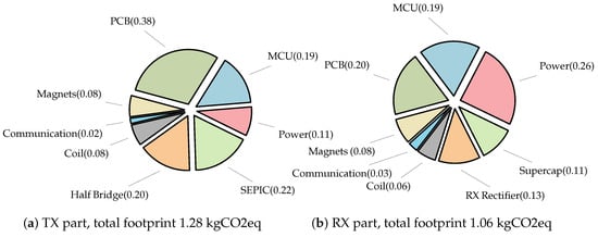
Figure 10.
LCA of transmitter and receiver part of contactless battery solution prototype (in kgCO2eq).
The MCU impact is modeled using a 90 nm technology node based on ST specifications [34]. For other ICs, such as DC/DC converters and battery management ICs, exact manufacturing nodes are often not disclosed by the manufacturers. TI uses predominantly 45 nm to 130 nm technology nodes for its ICs [35], while ST reports to use the BCD technology, predominantly in 110 nm for low-voltage power applications [36]. In this work, we therefore assumed the remaining ICs to be fabricated using a representative 90 nm technology node. The printed circuit board (PCB) is a two-layer board with Hot Air Solder Leveling (HASL) finish. The GaN FETs were selected to reduce the design’s environmental footprint. Their smaller die area for a given power or current rating, combined with faster switching capabilities, offers clear advantages [37]. For impact modeling purposes, the closest available silicon-based proxy was used. The wireless coils are approximated based on the copper weight and ferrite shielding materials [38], which slightly underestimates the total impact, as the processes for copper bending and coil assembly are not included. Compared to similar-sized PCB coils, their impact is significantly lower. The magnets are characterized as small neodymium magnets. Although they are not part of the prototype, they will be required in the final design and are therefore included in the LCA. The storage solution (supercapacitor) at the receiver side is modeled according to an activated carbon type with a capacity of 5 F. For the remaining passive components, the closest database or proxies are used.
As shown in Figure 10, the ICs and PCB have the highest contribution to the total environmental impact, while the small energy storage on the receiver side’s impact is limited. Similarly, the impact of a few (x3) small neodymium magnets to improve coil alignment remains limited. This indicated that the use of magnets is indeed advantageous for improving alignment and WPT efficiencies, without a significant initial environmental overhead. The total additional footprint of the system accounts for 2.34 kgCO2eq, of which 1.28 kgCO2eq originates from the transmitter and 1.06 kgCO2eq can be attributed to the receiver. To place these results in perspective, the carbon footprint for low- to medium-complexity devices with few sensors is estimated to account for 1 kgCO2eq to 10 kgCO2eq [39]. For instance, Ref. [39] calculated that a simple Philips Hue occupancy sensor has a footprint of approximately 1.4 kgCO2eq. This increases to 7.3 kgCO2eq for a home-connected assistant and to 10.4 kgCO2eq for a smartwatch. In comparison, a smartphone has a much larger footprint of about 70 kgCO2eq, with roughly 70% attributed to production [40]. This shows that our solution has a limited environmental impact.
Our design is made with the goal of evaluating key parameters of a swappable battery system, rather than being optimized for final production. The PCB area is intentionally larger to ease debugging. Due to the use of multiple dedicated ICs, lots of components would be redundant when optimized in a final design. ICs could be consolidated into a single IC in a final product, as done in Qi-compatible systems [41]. Figure 11 depicts the associated additional environmental impact of implementing an optimized version of the proposed WPT system. The modeling is based on existing Qi-compliant ICs, under the assumtion that the separate components of the prototype solution can be integrated into a single IC at the transmitter and receiver sides (including an estimate of the necessary PCB area). The total environmental impact of a UAV flight for 1 h, servicing a node, is also taken into account. A small 250 g UAV is assumed to be used optimally during its lifetime, and the energy consumption and extra batteries during its lifetime are taken into account. The results indicate that the UAV flight itself is only a small portion of the total additional environmental impact of the contactless battery solution. Apart from an initial additional manufacturing impact of 1.07 kgCO2eq, this approach facilitates reuse and creates opportunities for emissions reduction over time. If the alternative is replacing the entire IoT device and making it obsolete, this system becomes environmentally beneficial after just one swap.
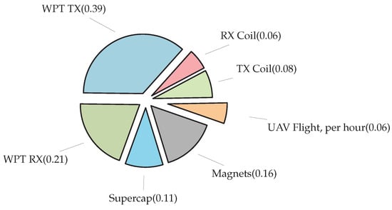
Figure 11.
UAV servicing environmental impact for an optimized solution (without energy storage at the receiver side), assuming implementation with commercial off-the-shelf (COTS) Qi-compatible components in a single IC. The total footprint is 1.07 kgCO2eq for TX and RX combined.
5.2. Selection of Energy Buffers
The selection of energy storage technology at the transmitter side benefits from being long-lasting, environmentally friendly, and having a high energy density, as it will be caried by a UAV. LFP is proposed due to its long cycle life (2000+ cycles), energy density (90–120 Wh/kg), intrinsic safety, and reliance on less critical materials compared to other lithium chemistries [24,25]. Alternatives such as nickel cobalt aluminum (NCA) (up to 200–260 Wh/kg, 500 cycles), nickel manganese cobalt (NMC) (150–200 Wh/kg, 1000–2000 cycles), and lithium cobalt oxide (LCO) (up to 240 Wh/kg, 500–1000 cycles) [42] offer higher energy density, but at the expense of safety, lifetime, or environmental impact. LFP is preferred when safety and longevity dominate, while NCA, LCO, NMC are attractive options when energy density is the primary concern.
At the receiver side, buffer selection depends on both energy demand and environmental footprint. For low-energy applications, a supercapacitor-based solution is chosen. While activated carbon supercapacitors offer extremely long cycle life, their impact during production is high (12.65–23 kgCO2eq/Wh or 21.194 gCO2eq/F) [43,44,45]. Bio-based supercapacitors, available as COTS devices with impacts as low as 5 gCO2eq/F [46], can significantly reduce this footprint. For higher average energy demand, increasing buffer capacity favors lithium-based batteries. Among these, LCO and lithium-ion manganese oxide (LMO) have the lowest environmental impact per watt-hour, while LFP, LTO, and NMC show higher impacts. Since the buffer is cycled multiple times per day, a lithium battery with a high cycle life is preferred, with LTO offering the longest cycle life of 10,000–25,000 cycles [24]. When the lifetime GWP is considered, i.e., the amount of gCO2eq per unit of energy when the battery gets used for its full cycle life, LTO batteries also offer clear advantages due to their high cycle life with 0.185 kgCO2eq/Wh and 7.4–18 gCO2eq/kWh lifetime GWP [24]. The trade-off lies in combining these environmental considerations with operational lifetime. For an application consuming 200 J/day, based on the typical amount of charge cycles, an LTO cell will last about 4–10 years, while a supercapacitor would last more than 205 years. The optimal choice depends on whether minimizing environmental impact or maximizing operational longevity is prioritized, alongside other weight or size constraints. Recent developments in Hybrid Ion Capacitors (HICs) demonstrate the combination of elevated energy density with high charge and pulse current capabilities while having a low leakage. This performance is achieved by integrating an electrostatic double-layer capacitor (EDLC)-type electrode with a battery-type electrode, a hybrid configuration that is gaining adoption in advanced energy-storage applications [47]. Its environmental impact is not yet well quantified, as this remains a relatively new technology.
5.3. Comparison to Other Alternative Solutions
Table 3 provides an overview of the proposed work in comparison with alternative solutions. Although the battery-to-IoT node efficiency of the current prototype is not the highest, its key advantage lies in the ease of battery replacement, eliminating the need for manual intervention, which could significantly reduce the long-term environmental impact. A detailed discussion of the alternative solutions is presented below.
Table 3.
Comparison of the proposed contactless battery solution with alternative approaches. * Efficiency is defined as the ratio of the incoming energy to the usable energy available at the IoT node.
Contact-based system. As an alternative to a WPT approach, a contact-based system with neodymium (NdFeB) or electromagnets could be used. Such a configuration would give higher power transfer efficiencies, but has several drawbacks. Direct connections with magnets are susceptible to corrosion and environmental degradation, as terminals must remain exposed to make contact. Protective surface treatments, such as gold plating, nanostructured silver alloy, or nickel plating, can mitigate these issues. The environmental footprint, especially for gold plating, is substantial, at 479 kgCO2eq/mm3 [48], corresponding to approximately 12 kgCO2eq for coating just four small magnets with a thickness of 1.5 μm. The lifetime of a plating with a thickness between 0.6 μm to 1 μm, is 10,000 cycles [49]. Exact lifetimes for mostly static operations are heavily dependent on the environment. Gold plating with 1.5 μm is suitable for connections that may be soldered or exposed to more aggressive environments, and offers superior protection against wear in moderate to high cycles [50]. Under mild conditions, with limited humidity, these treatment processes can match the expected operating lifetime of IoT devices. In harsher environments, such as outdoor installations with high humidity, temperature fluctuations, or exposure to corrosive agents, the protective layers degrade prematurely and/or may still occasionally require cleaning, which introduces manual labor into the system. Increasing plating thickness can extend the usable lifetime, but realistically, plated contacts are only suitable for operation in non-harsh conditions. In a contact-based system, costs are higher than in our proposed contactless battery solution due to the possibility of occasional maintenance. Exposed contacts may require occasional cleaning depending on the operating environment, thereby introducing manual labor. The cost of even a single hour of manual labor can easily exceed the one-time WPT hardware that enables fully automatic maintenance [51].
Replacement of complete system. An alternative to the proposed system is to retrieve the entire IoT device using a UAV, rather than replacing only the battery. This allows the battery to be integrated into the IoT node, eliminating the inefficiencies associated with WPT. The device could be completely encapsulated, providing enhanced protection against the environment. However, complete encapsulation may not be feasible for all use cases, for instance, when the sensor must remain exposed outside the casing. While this approach would require a larger UAV, LCA results, as shown in Figure 11, indicate that, even if the impact of UAV servicing would be higher, this is not the biggest impact of the system. According to [52], it takes only 70.1 gCO2eq to transport a packet over 2 km with a 3 kg UAV [52]. However, in fire-and-forget IoT systems, non-reusable batteries are typically used. Given an average environmental impact of 39.53 gCO2eq/Wh for non-rechargeable batteries [32], the manufacturing of a large 25 Wh non-rechargeable battery has an impact comparable to the additional overhead required for wireless battery replacement. However, electronics have a significantly longer lifespan than the battery itself. The initial environmental impact of the proposed system is higher due to the additional components that are required for the WPT. For very low-energy applications, the WPT environmental overhead may not be justified, and using a small non-rechargeable battery could be environmentally beneficial. Over long-term deployments, however, even after a single battery swap, the environmental impact of the battery swapping system will be lower compared to that of replacing the entire system, as our proposed system substantially reduces the environmental impact associated with the EoL stage. Replacing the entire system sustainably requires opening the IoT device upon retrieval, collecting the old battery, and installing a new one, an operation that involves significant manual labor. Replacing the complete system results in the highest costs, since either significant manual effort is needed to retrieve and disassemble the device to access the battery, or an entirely new IoT node must be fabricated for each replacement.
6. Conclusions and Future Work
This paper has presented an energy provisioning solution for IoT nodes that operate without contacts and hence opens opportunities for automated battery replacement.
System performance: The designed system successfully demonstrated the WPT functionality and overall efficiency feasibility. A transmitter-to-receiver efficiency of 72% has been achieved, confirming the feasibility of contactless energy provisioning for IoT nodes. The end-to-end efficiency of polling-based and interrupt-based applications is 58% and 46% respectively. The three-phase WPT data-flow has been proven feasible for both application types. Although the WPT link has a lower efficiency compared to a direct connection, it offers the crucial advantage of enabling battery replacement at EoL, thereby supporting modular sustainable design principles.
Life cycle assessment: The LCA indicates that the largest contributor to environmental impact is the initial manufacturing of extra components, predominantly the ICs and PCB area, while the impact of the UAV flight itself remains very limited. The total additional footprint of the system accounts for 2.34 kgCO2eq, of which 1.28 kgCO2eq originates from the transmitter and 1.06 kgCO2eq can be attributed to the receiver. In contrast, the UAV contributed only 60 gCO2eq per flight hour, showing that the flight impact is minimal compared to hardware. For an optimized solution, implementing the WPT in a single IC, the environmental impact reduces to 1.07 kgCO2eq, including a UAV flight.
Design trade-offs: Lithium-based chemistries, especially LFP, are most suitable as transmitter-side batteries as they combine relatively high energy density with long cycle life while relying less on critical materials than other battery types. The choice of energy buffer at the receiver strongly influences both operational performance and sustainability. For high-energy applications, a small LTO battery or HIC provides the best balance, whereas for low-power applications, a supercapacitor is more appropriate. Compared to alternative approaches, including contact-based charging, full device retrieval, or non-rechargeable batteries, the proposed contactless system achieves a balance between environmental impact, operational longevity, and ease of deployment, particularly in hard-to-access or hazardous environments.
In future work, the system can be improved in a number of ways.
Efficiency and electronic circuits: The efficiency can be significantly improved by eliminating the voltage drop across the diodes, particularly in low-power transfer, when the receiver voltage is low. The charging efficiency of the supercapacitor can be improved by only charging with a constant-current approach. It could increase the charging time and would eliminate inefficiencies in the latter part of the charging cycle. Further optimization of the SEPIC, DC/DC converters, and coil Q-factors can improve the overall system efficiency. The load dependence of the system could be optimized by employing a higher-order, e.g., LCC compensation, topology [21] instead of the simpler S-S compensation. This could improve the power transfer efficiency across varying load conditions [53]. Hybrid energy storage solutions, such as HICs, show promise for combining high energy density, low leakage, and long cycle life on the receiving side.
Integration: The MCU on the receiver side could also function as the application MCU, thus reducing overall environmental impact, system complexity, and power consumption. The system could be made compatible with other energy harvesting sources, such as solar or RF to supplement WPT. Efforts should be made towards miniaturizing the design, integrating most logic and drivers into a single IC. This would not only reduce the size and complexity of the system but also reduce the overall carbon footprint.
Validation and cooperation: The system needs to be validated in an application context and there should be cooperation with application experts to progress the technology in directions that make them attractive for adoption. Experts should work towards a standard making the system more universally adoptable and interoperable.
Author Contributions
Conceptualization, J.C., L.V.d.P., and L.D.S.; methodology, J.C.; software, J.C.; validation, J.C.; formal analysis, J.C.; investigation, J.C.; resources, J.C.; data curation, J.C.; writing—original draft preparation, J.C., L.V.d.P., and L.D.S.; writing—review and editing, L.V.d.P. and L.D.S.; visualization, J.C.; supervision, L.V.d.P. and L.D.S.; project administration, L.V.d.P. and L.D.S.; funding acquisition, L.V.d.P. and L.D.S. All authors have read and agreed to the published version of the manuscript.
Funding
This work is co-funded by the European Union under Grant Agreement 101191936 (Sustain-6G) and under Grant Agreement No. 101192113. (AMBIENT-6G).
Data Availability Statement
The design is shared in open source on GitHub at https://github.com/DRAMCO/Contactless-Battery-Solution-for-Sustainable-IoT-Devices (accessed on 14 October 2025).
Conflicts of Interest
The authors declare no conflicts of interest.
References
- Hasan, K.; Tom, N.; Yuce, M.R. Navigating Battery Choices in IoT: An Extensive Survey of Technologies and Their Applications. Batteries 2023, 9, 580. [Google Scholar] [CrossRef]
- Callebaut, G.; Leenders, G.; Van Mulders, J.; Ottoy, G.; De Strycker, L.; Van der Perre, L. The Art of Designing Remote IoT Devices—Technologies and Strategies for a Long Battery Life. Sensors 2021, 21, 913. [Google Scholar] [CrossRef]
- Hossein Motlagh, N.; Taleb, T.; Arouk, O. Low-Altitude Unmanned Aerial Vehicles-Based Internet of Things Services: Comprehensive Survey and Future Perspectives. IEEE Internet Things J. 2016, 3, 899–922. [Google Scholar] [CrossRef]
- Williams, A.J.; Torquato, M.F.; Cameron, I.M.; Fahmy, A.A.; Sienz, J. Survey of Energy Harvesting Technologies for WSNs. IEEE Access 2021, 9, 77493–77510. [Google Scholar] [CrossRef]
- Czyża, S.; Szuniewicz, K.; Kowalczyk, K.; Dumalski, A.; Ogrodniczak, M.; Zieleniewicz, L. Assessment of Accuracy in Unmanned Aerial Vehicle (UAV) Pose Estimation with the REAL-Time Kinematic (RTK) Method on the Example of DJI Matrice 300 RTK. Sensors 2023, 23, 2092. [Google Scholar] [CrossRef]
- Grlj, C.G.; Krznar, N.; Pranjić, M. A Decade of UAV Docking Stations: A Brief Overview of Mobile and Fixed Landing Platforms. Drones 2022, 6, 17. [Google Scholar] [CrossRef]
- Cui, Y.; Wang, C.; Hu, Q.; Xu, B.; Song, X.; Yuan, Z.; Zhu, Y. A Novel Positioning Method for UAV in GNSS-Denied Environments Based on Mechanical Antenna. IEEE Trans. Ind. Electron. 2024, 71, 13461–13469. [Google Scholar] [CrossRef]
- Delabie, D.; Feys, T.; Buyle, C.; Cox, B.; Van der Perre, L.; De Strycker, L. Echoes of Accuracy: Enhancing Ultrasonic Indoor Positioning for Energy-Neutral Devices With Neural Network Approaches. IEEE J. Indoor Seamless Position. Navig. 2025, 3, 227–244. [Google Scholar] [CrossRef]
- Hu, Y.; Yuan, X.; Zhang, G.; Schmeink, A. Sustainable Wireless Sensor Networks With UAV-Enabled Wireless Power Transfer. IEEE Trans. Veh. Technol. 2021, 70, 8050–8064. [Google Scholar] [CrossRef]
- Cetinkaya, O.; Ozger, M.; De Roure, D. Coverage Performance of UAV-Powered Sensors for Energy-Neutral Networks with Recharging Stations. In Proceedings of the ICC 2023—IEEE International Conference on Communications, Rome, Italy, 28 May–1 June 2023; pp. 2902–2908. [Google Scholar] [CrossRef]
- Liu, Y.; Dai, H.N.; Wang, H.; Imran, M.; Wang, X.; Shoaib, M. UAV-enabled data acquisition scheme with directional wireless energy transfer for Internet of Things. Comput. Commun. 2020, 155, 184–196. [Google Scholar] [CrossRef]
- De Silva, S.C.; Phlernjai, M.; Rianmora, S.; Ratsamee, P. Inverted Docking Station: A Conceptual Design for a Battery-Swapping Platform for Quadrotor UAVs. Drones 2022, 6, 56. [Google Scholar] [CrossRef]
- Hoang, M.; Ov, A.; Chen, S.; Huynh, D.; Vega, J.; Kim, N.; Karwal, Y.; Dobbs, S.; Yu, Z. Design of Autonomous Battery Swapping for UAVs. In Proceedings of the AIM, 2024, San Francisco, CA, USA, 10–13 June 2024; pp. 353–358. [Google Scholar] [CrossRef]
- Van Mulders, J.; Cappelle, J.; Goossens, S.; De Strycker, L.; Van der Perre, L. UAV-Based Servicing of IoT Nodes: Assessment of Ecological Impact. Sensors 2023, 23, 2291. [Google Scholar] [CrossRef] [PubMed]
- Cappelle, J. DRAMCO Github. Available online: https://github.com/DRAMCO/Contactless-Battery-Solution-for-Sustainable-IoT-Devices (accessed on 20 January 2025).
- Saini, J.; Dutta, M.; Marques, G. A comprehensive review on indoor air quality monitoring systems for enhanced public health. Sustain. Environ. Res. 2020, 30, 6. [Google Scholar] [CrossRef]
- Buyle, C.; Thoen, B.; Cox, B.; Alleman, M.; Wielandt, S.; De Strycker, L. Ultra-Low-Power Smart Sensing Platform for Urban Sound Event Monitoring. In Proceedings of the 2019 Symposium on Information Theory and Signal Processing in the Benelux. WIC, Ghent, Belgium, 28–29 May 2019; pp. 35–40. Available online: https://w-i-c.org/proceedings/proceedings_SITB2019.pdf (accessed on 9 September 2025).
- ITS-PE-1010—Red Magnetics. Available online: https://www.red-magnetics.com/en/product-groups/electromagnets/permanent-electromagnets/its-pe-1010/ (accessed on 2 January 2025).
- Graniteriverlabs. Evolution of Qi Wireless Charging Standard & What’s New with Qi2. Available online: https://www.graniteriverlabs.com/en-us/technical-blog/qi2-wireless-charging-standards-evolution (accessed on 9 September 2025).
- van Schuylenbergh, K.; Puers, R. Inductive Powering: Basic Theory and Application to Biomedical Systems; Analog Circuits and Signal Processing; Springer: Dordrecht, The Netherlands, 2009. [Google Scholar]
- Shevchenko, V.; Husev, O.; Strzelecki, R.; Pakhaliuk, B.; Poliakov, N.; Strzelecka, N. Compensation Topologies in IPT Systems: Standards, Requirements, Classification, Analysis, Comparison and Application. IEEE Access 2019, 7, 120559–120580. [Google Scholar] [CrossRef]
- Karimi, M.J.; Jin, M.; Zhou, Y.; Dehollain, C.; Schmid, A. Wirelessly Powered and Bi-Directional Data Communication System With Adaptive Conversion Chain for Multisite Biomedical Implants Over Single Inductive Link. IEEE Trans. Biomed. Circuits Syst. 2024, 18, 636–647. [Google Scholar] [CrossRef] [PubMed]
- Wireless Power Consortium. Qi Specification v2.1. Available online: https://www.wirelesspowerconsortium.com/media/303pxv0x/qi-v21-public.zip (accessed on 10 September 2025).
- Peters, J.F.; Baumann, M.; Zimmermann, B.; Braun, J.; Weil, M. The environmental impact of Li-Ion batteries and the role of key parameters—A review. Renew. Sustain. Energy Rev. 2017, 67, 491–506. [Google Scholar] [CrossRef]
- Science, L. Europe’s ‘New’ Periodic Table Predicts Which Elements Will Disappear in the Next 100 Years. Available online: https://www.livescience.com/64596-new-periodic-table-shows-helium-scarcity.html (accessed on 7 November 2022).
- PulsesPlus™ Series—Tadiran Batteries. Available online: https://tadiranbat.com/products/pulsesplus-series/ (accessed on 3 January 2025).
- Peaktech. Peaktech 6225A User Manual. Available online: https://www.peaktech.de/media/60/9a/e5/1703674474/PeakTech_6225A_6226_12-2023_DE-EN.pdf (accessed on 2 October 2025).
- Korad. Korad KEL103 Electronic Load User Manual. Available online: https://static.eleshop.nl/mage/media/downloads/kel-103_user_manual.pdf (accessed on 2 October 2025).
- TI. INA230 36V, 16-Bit, I2C Output Current, Voltage and Power Monitor with Alert Datasheet. Available online: https://www.ti.com/lit/ds/symlink/ina230.pdf (accessed on 2 October 2025).
- Kao, S.K. A CMOS Active Rectifier with Time Domain Technique to Enhance PCE. Electronics 2021, 10, 1450. [Google Scholar] [CrossRef]
- Eaton. The Major Differences Between Supercapacitors and Batteries; Technical Report; Eaton: Norwich, UK, 2022. [Google Scholar]
- Sphera. Product Sustainability (GaBi) Data Search Sphera. Available online: https://sphera.com/product-sustainability-gabi-data-search/ (accessed on 24 November 2023).
- Earthster. EF3.1 Impact Categories|Earthster Knowledge Base. Available online: https://docs.earthster.org/en/articles/6840014-ef3-1-impact-categories (accessed on 6 March 2025).
- STMicroelectronics. STM32 wireless MCUs. Available online: https://www.st.com/en/microcontrollers-microprocessors/stm32-wireless-mcus.html?fbclid=IwY2xjawF– (accessed on 18 August 2025).
- TI. The Importance of Ensuring Supply for Foundational Semiconductor Chips. Available online: https://www.ti.com/about-ti/newsroom/company-blog/the-importance-of-ensuring-supply-for-foundational-semiconductor-chips.html (accessed on 13 August 2025).
- STMicroelectronics. BCD—Bipolar-CMOS-DMOS. Available online: https://www.st.com/content/st_com/en/about/innovation---technology/BCD.html (accessed on 13 August 2025).
- Daryanani, S. GaN Power ICs Lead the Way to Sustainability. Available online: https://www.powerelectronicsnews.com/gan-power-ics-lead-the-way-to-sustainability/ (accessed on 14 August 2025).
- Gómez, P.; Elduque, D.; Pina, C.; Javierre, C. Influence of the Composition on the Environmental Impact of Soft Ferrites. Materials 2018, 11, 1789. [Google Scholar] [CrossRef]
- Pirson, T.; Bol, D. Assessing the embodied carbon footprint of IoT edge devices with a bottom-up life-cycle approach. J. Clean. Prod. 2021, 322, 128966. [Google Scholar] [CrossRef]
- Moreau, N.; Pirson, T.; Le Brun, G.; Delhaye, T.; Sandu, G.; Paris, A.; Bol, D.; Raskin, J.P. Could Unsustainable Electronics Support Sustainability? Sustainability 2021, 13, 6541. [Google Scholar] [CrossRef]
- TI. bq5105xB High-Efficiency Qi v1.2-Compliant Wireless Power Receiver and Battery Charger Datasheet. Available online: https://www.ti.com/lit/ds/symlink/bq51051b.pdf (accessed on 11 September 2025).
- BU-205: Types of Lithium-Ion—Battery University. Available online: https://batteryuniversity.com/article/bu-205-types-of-lithium-ion (accessed on 14 August 2025).
- Cossutta, M.; Vretenar, V.; Centeno, T.A.; Kotrusz, P.; McKechnie, J.; Pickering, S.J. A comparative life cycle assessment of graphene and activated carbon in a supercapacitor application. J. Clean. Prod. 2020, 242, 118468. [Google Scholar] [CrossRef]
- Kamali, A.K.; Glogic, E.; Keppetipola, N.M.; Sonnemann, G.; Toupance, T.; Cojocaru, L. Prospective Life Cycle Assessment of Two Supercapacitor Architectures. Acs Sustain. Chem. Eng. 2023, 11, 15898–15909. [Google Scholar] [CrossRef]
- Raffeck, P.; Posner, S.; Wagemann, P. CO2CoDe: Towards Carbon-Aware Hardware/Software Co-Design for Intermittently-Powered Embedded Systems. Sigenergy Energy Inform. Rev. 2025, 4, 127–133. [Google Scholar] [CrossRef]
- Supercapacitors—LIGNA Energy. Available online: https://www.lignaenergy.com/ (accessed on 13 August 2025).
- Sun, J.; Luo, B.; Li, H. A Review on the Conventional Capacitors, Supercapacitors, and Emerging Hybrid Ion Capacitors: Past, Present, and Future. Adv. Energy Sustain. Res. 2022, 3, 2100191. [Google Scholar] [CrossRef]
- Ulrich, S.; Trench, A.; Hagemann, S. Gold mining greenhouse gas emissions, abatement measures, and the impact of a carbon price. J. Clean. Prod. 2022, 340, 130851. [Google Scholar] [CrossRef]
- Song, J.; Koch, C.; Wang, L. Correlation between Wear Resistance and Lifetime of Electrical Contacts. Adv. Tribol. 2012, 2012, 893145. [Google Scholar] [CrossRef][Green Version]
- Bondhus, B. Gold Plating Thickness of Connectors and Contacts. Available online: https://advancedplatingtech.com/wp-content/uploads/2018/04/Gold-Plating-Thickness-Blog-Advanced-Plating-Technologies-1.pdf (accessed on 1 October 2025).
- Eurostat. Hourly Labour Costs. Available online: https://ec.europa.eu/eurostat/statistics-explained/index.php?title=Hourly_labour_costs (accessed on 3 October 2025).
- Rodrigues, T.A.; Patrikar, J.; Oliveira, N.L.; Matthews, H.S.; Scherer, S.; Samaras, C. Drone flight data reveal energy and greenhouse gas emissions savings for very small package delivery. Patterns 2022, 3, 100569. [Google Scholar] [CrossRef] [PubMed]
- Liu, X.; Clare, L.; Yuan, X.; Wang, C.; Liu, J. A Design Method for Making an LCC Compensation Two-Coil Wireless Power Transfer System More Energy Efficient Than an SS Counterpart. Energies 2017, 10, 1346. [Google Scholar] [CrossRef]


Disclaimer/Publisher’s Note: The statements, opinions and data contained in all publications are solely those of the individual author(s) and contributor(s) and not of MDPI and/or the editor(s). MDPI and/or the editor(s) disclaim responsibility for any injury to people or property resulting from any ideas, methods, instructions or products referred to in the content. |
© 2025 by the authors. Licensee MDPI, Basel, Switzerland. This article is an open access article distributed under the terms and conditions of the Creative Commons Attribution (CC BY) license (https://creativecommons.org/licenses/by/4.0/).