Article

A Survey of Electromagnetic Influence on UAVs from an EHV Power Converter Stations and Possible Countermeasures

1
Beijing Key Laboratory of Network System Architecture and Convergence, Beijing Laboratory of Advanced Information Network, Beijing University of Posts and Telecommunications, Beijing 100876, China
2
Department of Electrical Engineering, Tsinghua University, Beijing 100084, China
3
Department of Electrical and Computer Engineering, NOVA School of Sciences and Technology, University NOVA of Lisbon, 2829-516 Lisboa, Portugal
*
Authors to whom correspondence should be addressed.
Electronics 2021, 10(6), 701; https://doi.org/10.3390/electronics10060701
Submission received: 22 February 2021 / Revised: 2 March 2021 / Accepted: 4 March 2021 / Published: 17 March 2021
(This article belongs to the Special Issue Drones and UAVs Energy Management Progress and Challenges)

Abstract

:
It is inevitable that high-intensity, wide-spectrum electromagnetic emissions are generated by the power electronic equipment of the Extra High Voltage (EHV) power converter station. The surveillance flight of Unmanned Aerial Vehicles (UAVs) is thus, situated in a complex electromagnetic environment. The ubiquitous electromagnetic interference demands higher electromagnetic protection requirements from the UAV construction and operation. This article is related to the UAVs patrol inspections of the power line in the vicinity of the EHV converter station. The article analyzes the electromagnetic interference characteristics of the converter station equipment in the surrounding space and the impact of the electromagnetic emission on the communication circuits of the UAV. The anti-electromagnetic interference countermeasures strive to eliminate or reduce the threats of electromagnetic emissions on the UAV’s hardware and its communication network.

1. Introduction

With the rapid development of modern science and technology, the co-existence of sophisticated megawatt electric power converters, together with highly sensitive electronic equipment, has become increasingly widespread. The high-density and wide-spectrum electromagnetic emissions generated by the power electronics equipment operation fill the entire space, forming a complex electromagnetic environment. That intensive electromagnetic field inevitably affects the other electronic equipment and systems. The complex electromagnetic environment requires electronic equipment and power supplies to have robust and ultimate electromagnetic compatibility. For any electronic equipment working in an electromagnetically polluted environment, the suppression of electromagnetic interference has become nowadays, a necessary accompanying technology.
The converter station is the most important part of the UHV DC project, in addition to the transmission line part. Through the converter station, the direct current and the alternating current sides of the power system, are bidirectionally converted to satisfy the power system’s requirements for safety, stability and power quality. The main structure of the converter station includes a valve hall, a converter transformer, AC switchyard, smoothing reactor, filter, reactive power compensation equipment, etc. The high-voltage converter valve is subjected to high electrical stress, large energy transients, and high electromagnetic noise intensity. The stronger and weaker electronic devices are in close vicinity and the mutual coupling of the system is tight. Hence, the electromagnetic interference by coupling mechanisms inside the high-voltage power converter valve is complex.
To ensure the quality of service and the safety of the electrical transmission, the inspection of the power lines and the work areas in its vicinity, has always been the core work of the power system management. In recent years, with the deepening integration of artificial intelligence into the power system industry, unmanned equipment (UAVs), unmanned vehicles, and inspection robots have been widely used in this application field, thereby reducing operating costs and improving operating efficiency. The equipment inspection robot system uses autonomous or remote-control devices, to inspect the outdoor high-voltage equipment outside of the unattended or less-attended converter stations. The robotic equipment can detect defects in the power equipment, inside and outside of the power station. It can detect undesirable objects hanging and other abnormal phenomena in time. The inspection robot will automatically alarm or troubleshoot the situation, according to the set rules. With their capacity of being independent of the terrain, UAVs have unparalleled advantages in the operation of power equipment in remotely inspected locations.
Whether it is communication between UAVs or direct communication between UAVs and ground transmission stations, they all rely heavily on the mobile wireless network between them. Due to the influence of the multipath fading and Doppler frequency shift in the mobile communication system itself, the wireless channel is extremely variable, which will have a strong negative effect for any modulation technology [1]. In addition, the electromagnetic pulses from the power converter equipment will also affect harmfully the electronic components of the UAVs.
When drones are used in converter station inspections, the strong electromagnetic fields generated by the transmission lines and equipment will strongly interfere with the communication and control systems of the drones that are flying close to the emission. In severe cases, they will cause the flight control to fail and the drone to crash, and even endanger the power lines. Therefore, analyzing the characteristics of the interference from the power converter station equipment to UAVs is not only of great significance for the safe use of inspection UAVs, but also has considerable value as a reference for other intelligent equipment operating in complex electromagnetic environments.
This article will take the converter equipment inspection drone as an example, a sensor to analyze the electromagnetic interference characteristics of the power converter station in the surrounding environment. The article will warn of the impact of electromagnetic emissions on the communication circuits and the control of the drone. It will discuss the methods of electromagnetic protection and show the impact of the complex electromagnetic environment on UAVs or other electronic equipment.

2. Electromagnetic Interference Characteristics of Converter Station to the Surrounding Environment

To understand the electromagnetic interference characteristics of the converter station equipment and the impact on the UAV, it needs first to identify the electromagnetic emission generated by the power converter station equipment.

2.1. Electromagnetic Interference in Converter Station

The converter station is the main part of the High Voltage Direct Current (HVDC) transmission system. Its function is to complete the interface between the AC and DC power systems. Its core structure is the power electronic converter, constructed by high-voltage (HV) semiconductor switches connected in HV electronic valves. The electromagnetic emission of the HVDC converter station is mainly caused by the switching of the valves of the converter station. The converter valves will alternately open and break off when working, and that leads to rapid transients of the switching voltage and internal current of the valves. This type of electromagnetic emission is characterized by the transmission of energy, which spreads a wide and continuous spectrum of noise. In addition, the commutation of the semiconductor devices (inside the valves) may produce corona discharge, sparks, etc. This may cause additional electromagnetic interference, and the switching operation transient processes will result in high frequency and larger spectrum electromagnetic noise. Therefore, the main source of interference in the converter station is the converter valve, and the secondary source of interference is the other equipment [2,3,4,5,6,7,8,9,10,11,12,13]. The following analysis is studying those sources of interference.

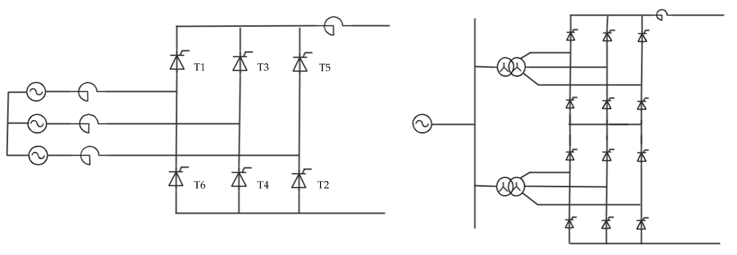
2.2. Analysis of Electromagnetic Interference from the Converter Valves

From this moment on, the term valve will be used also to generally name the full group (matrix) of HV valves, as it is a more compact description.
The converter valve is the core equipment of the converter station. Its function is to accomplish the conversion between AC and DC. The semiconductor devices widely used in HV valves are mainly thyristors, but recently, the IGBTs made of new semiconductor materials are also used. The converter valve bridge arms consist of thyristors, connected in series and parallel. Each switching element in Figure 1 is a complex set of many thyristors, controlled synchronously to be switched on and off. The valves T1, T2 … are connected usually in the form of 6-pulse converters or 12-pulse converters [5]. The classic schematic diagrams are shown in Figure 1.
The basic principle of the six-pulse converter valve is a typical three-phase full-bridge rectifier circuit. During each period, the trigger circuit sends commands to the six valves, where each switch or valve is a combination of thyristors. In the case of a rectifier, as in Figure 1, a relatively flat and stable DC voltage waveform is obtained after the filter. The flatness of the 12-pulse rectifier is almost perfect and economically it is the preferred configuration for high power converters, although the transformer is more complicated. The number of switching transients per period is also higher in case of 12-pulse converters.
The thyristor has a cathode, and anode, and a control electrode, a gate, usually commanded by the optical cable, for these HV applications. After the thyristor is turned on, the control becomes impossible. This behavior requires that the thyristor returns to be disconnected by recovering the huge quantity of charges accumulating in it. So, the thyristor needs to suffer from the brutal reverse of the load current, when the voltage of the anode becomes negative and/or the current through the anode is inverted. Since the voltage drop on the thyristor is close to 0 when it is turned on, the terminal voltage will change drastically at the moment of turn-off. In addition, when the thyristor is turned off, the terminal voltage of the converter valve is not only affected by its own high-impedance widescreen characteristics, but also electromagnetic interference from other converter valves, so the terminal voltage fluctuates accordingly. Severe voltage fluctuations produce high-frequency electromagnetic components. During the normal operation of the converter station, the valve, each one a combination of many thyristors, keeps repeating the process of switching on and off, thereby generating a steady stream of high-frequency electromagnetic interference [14].
Thirteen thyristors are connected in series with two saturable reactors, and then connected in parallel with a voltage equalizing capacitor to form each valve assembly. Two valve components are connected in series to form a valve module. Three valve modules are connected in series to form a converter valve arm. Four converter valves are connected in series to form a valve tower. Three valve towers form a complete converter valve. In the valve hall (Figure 2), the most important component is the converter valve.

2.3. Analysis of Electromagnetic Interference of Other Equipment

In addition to the interference caused by the converter valve in the converter station, the corona and discharge phenomena of various high-voltage equipment will also cause electromagnetic interference. The frequency range of these electromagnetic interferences is between 100 kHz and 10 MHz. However, as long as the operating voltage is less than the corona initiation voltage, the equipment will not be corona. After the shielding ring is installed, the corona initiation voltage can basically be guaranteed to be above the normal operating voltage. Therefore, electromagnetic interference caused by corona can be avoided under normal circumstances.
In addition, operational operations can also cause electromagnetic interference to the converter station, such as outage, standby, lockout, unlocking, and open circuit experiments. Although these operations will cause large electromagnetic interference, for the application of UAV inspection, it can be avoided by the reasonable arrangement of converter station actions and UAV inspection time [5].
In summary, considering the application of drones, the electromagnetic interference of the converter station is mainly caused by the normal switching action of the converter valve. Other minor interferences, such as corona, converter station operation, etc., can be avoided. Therefore, these effects can be ignored when designing, and the electromagnetic interference characteristics of the converter valve can be mainly considered [5].

3. The Impact of the Electromagnetic Interference on Drones

The electromagnetic environment in which UAV systems of different purposes perform their prescribed tasks is different. Therefore, the electromagnetic environment is the basis for proposing and determining the electromagnetic compatibility requirements of UAV systems. The sources of electromagnetic interference suffered by UAV systems can be divided into electromagnetic interference within the system and electromagnetic interference outside the system [16]. Table 1 shows the sources of UAV electromagnetic interference and coupling methods.
For the electromagnetic coupling between the low-frequency analog signal port and the power port, an appropriate electromagnetic interference filter can generally be effectively suppressed. The electromagnetic coupling of radio frequency ports and digital signal ports is very complicated.

3.1. Influence of Electromagnetic Interference of Converter Station on UAV Communication

The measurement and control communication system that the UAV will be affected by electromagnetic interference can be divided into two parts [17]: UAV data link communication system, which is responsible for transmitting the uplink control signal and the downlink image transmission signal. UAV navigation and positioning system, which is responsible for its own positioning and navigation.

3.1.1. Impact on UAV Data Link Communication System

The UAV realizes the information interaction with the control terminal through the data link [18,19,20]. The control terminal sends control instructions to the drone through the uplink remote control link, and the drone status parameters and task collection information are fed back to the control terminal through the downlink telemetry link. UAV data links usually use IEEE 802.11 a/n/ac, cellular 3G/4G, or analog systems [21], but these three modes have their own shortcomings. The working frequency band of the IEEE 802.11 protocol is 2.4 GHz, which is within the interference range of the converter equipment, and the broadband interference caused by the converter equipment makes the communication load change the channel and the regional problem cannot be solved. When the interference is too large and the signal-to-noise ratio is lower than a certain threshold, the transmission rate can be automatically reduced from 11 Mb/s to 5.5 Mb/s, or it can be reduced to 2 Mb/s or 1 Mb/s of direct sequence spread spectrum technology. rate. At this time, the information transmission rate cannot even guarantee the flight safety of the drone itself, let alone complete the task. Cellular systems are simple and easy to use and are often provided by mobile operators. They are based on the 802.11 a/b/g standard. They have all the aforementioned shortcomings and are limited by the coverage and signal strength of the cellular network. The anti-interference ability is not strong. Quality is easily affected. The analog signal is easily attenuated during the transmission process, is easily interfered, and has insufficient security. The spectrum efficiency is low (100% duty cycle transmission is required, and cannot work in parallel with other communication technologies). Its advantage lies in almost direct radio frequency signals. Modulation, the delay is very low. The current use of analog signals in UAV communication is not common, so this article will not focus on the description.
On the other hand, the UAV communication system, as a special mobile communication system, is inevitably affected by multipath fading and Doppler shift. Due to the wide antenna beam of the communication ground station, the radio signal is divided into two or more copies of the signal and arrives at the receiving antenna through more than multiple paths due to the influence of many factors such as ground features, topography, and the moving speed of the transmitting and receiving ends. In this process, these signal waves interfere, which is called Intersymbol interference (ISI). Because each reflected wave passes through a different path, which affects its phase and amplitude when it reaches the receiving end, when the receiving antenna mixes these signals, there will be distortions in the phase and amplitude, that is, “fading” [22]. Commonly used diversity reception, equalization transformation and channel coding to overcome. Under the broadband interference of the converter equipment, whether the multipath effect has any special effects, and the application performance of the anti-fading technology is still unclear, and further experimental observation is needed.
Although the electromagnetic spectrum space exists objectively, the current UAV does not have the ability to identify electromagnetic interference, let alone determine whether the interference frequency will fall within the working frequency band, and there are huge security risks [20]. If the data link is interfered, it may cause the UAV to lose connection or even crash out of control. If it affects the power transmission equipment, it will cause more serious safety accidents. Therefore, the study of the impact of electromagnetic interference on the UAV data link is very important.
Literature [17] used a certain type of UAV as the test object to build a continuous wave irradiation test system, and found the interference effect through electromagnetic irradiation. The result found that the UAV main remote-control data link is easily affected by high-frequency continuous wave interference. The lower the frequency, the larger the loss-of-lock sensitivity threshold. The single-frequency continuous-wave will interfere with the UAV’s main remote-control data link, which is manifested as a loss of lock phenomenon. At this time, the ground control station loses control of the UAV [17].
The continuous wave electromagnetic radiation effect test system for UAV (Figure 3) has three module: continuous wave radiation emission system, subject (the tested UAV), and dynamic monitoring system (Table 2).
In addition, based on the analysis of the UAV body structure, it can be seen that electromagnetic interference may have an effect on the UAV main remote-control data link through the following four channels [23].
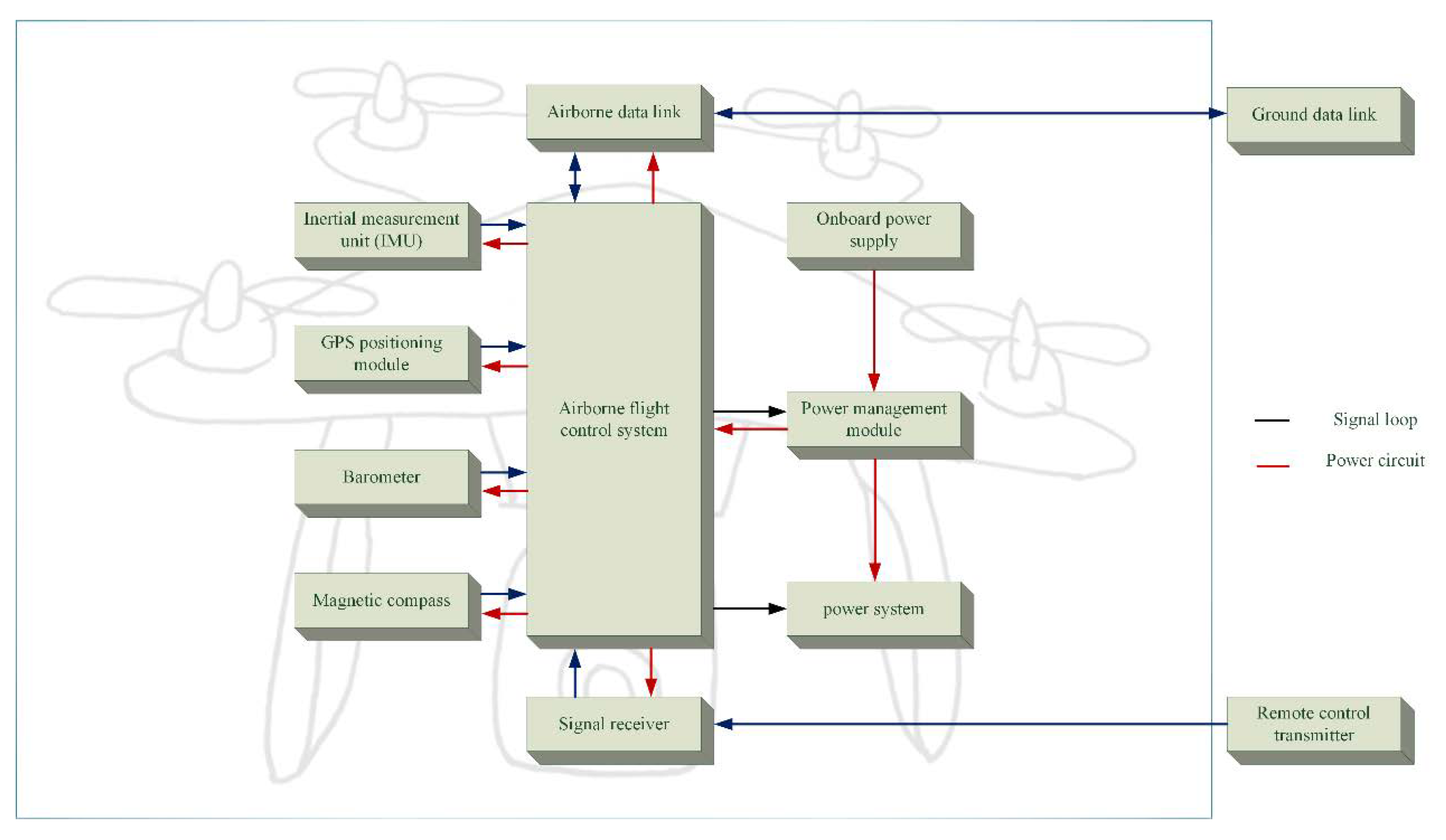
  • The main remote-control antenna is the aircraft signal receiver. The antenna has the strongest signal receiving capability within the normal working frequency band of the UAV. Therefore, the same frequency interference can easily affect the demodulation of the digital circuit, resulting in an excessive bit error rate. It will receive interference signals with a certain energy, and the duplexer is the only way for interference current conduction, and its filtering attenuation ability directly affects the working state of the subsequent circuit.
  • In order to carry more mission loads while satisfying the purpose of lightness of the fuselage, the fuselage of the UAV generally uses composite materials. Electromagnetic waves can easily pass through the fuselage shell and enter the cabin, which increases the complexity of the internal electromagnetic environment.
  • In order to achieve the purpose of structural connection and ventilation, the surface of the fuselage has different degrees of holes, openings and other electrical unconnected parts, which are likely to cause electromagnetic leakage.
  • Due to the limited power of the on-board backup battery, utility power is usually used during the near-field debugging of the drone, and the cable connection may introduce external interference.
Therefore, the UAV main remote-control antenna is the main coupling channel that introduces interference and causes the main remote-control data link to lose lock.
According to the various functional subsystem modules, the impact of electromagnetic interference on the data link between the UAV and the ground console is manifested by the performance degradation of each subsystem. The line-following UAV is exposed to the electromagnetic radiation of the converter station. Systems that may degrade performance or lose control include digital signal transmission, sensor signal transmission, information transmission, and automatic control signal transmission.
Since drones need to carry recording and camera equipment to perform flight missions, image transmission must be completed by wireless communication. Under the effect of electromagnetic interference, the image signal will be distorted, the image pixels will be reduced, the definition will be worse, and the error will increase. Once the interference intensity exceeds the capacity of the sensitive equipment, the image information will not be received at all, and the communication with the ground equipment will even be interrupted [24].
Much information is transmitted by digital signals inside the UAV. Electromagnetic interference increases the bit error rate of the digital system and reduces the reliability of the signal. In severe cases, information loss or information errors will occur. Due to the existence of electromagnetic interference, the bit error rate of wireless communication can only be maintained at the level of 10 5 usually the bit error rate of digital signal transmission is at the level of 10 7 , and the total bit error rate of the internal data transmission of the electronic computer is generally 10 12 level) [25].
UAV airborne electronic equipment and instrumentation are the most sophisticated data indicating equipment among UAVs. Electromagnetic interference will reduce the reference value of pointer data [26].
When the automatic control system receives electromagnetic interference, it may lose control and malfunction, which will reduce the reliability and effectiveness of the control system and endanger safety [27]. Sensitive electronic equipment and electronic circuits in the control system are more sensitive to electromagnetic interference. In addition, stepping motors, low-voltage electromagnetic switches, relays and other equipment are also sensitive to electromagnetic interference.
Literature [28] conducted a radiation interference experiment on a UAV in a microwave anechoic chamber. When the interference field strength reached 10 V/m, at (80 MHz∼1000 MHz) and (1000 MHz∼2750 MHz) frequencies, the antenna direction regardless of the horizontal pole When the polarization is still vertical, although the drone’s engine can work at normal idling speed, the communication between the drone and the ground is interrupted, and the controller cannot control the steering stepper motor.

3.1.2. Impact on UAV Navigation and Positioning System

Corona discharge, insulator pollution flashover, and electromagnetic scattering in the environment of HVDC converter stations will all affect the GPS positioning accuracy of line-following drones.
Corona discharge is a plasma discharge that occurs on the surface of an insulator. When some insulators are damaged and their performance decreases, other normal insulators may withstand higher voltages and generate very strong electromagnetic fields [29]. In addition, when the potential gradient on the surface of the transmission line reaches a certain value, the air close to the wire will also be ionized, and then corona discharge will occur. Insulator pollution flashover is a flashover discharge caused by serious contamination on the surface of the insulator, which also generates a strong electromagnetic field [30]. In addition, when the GPS signal transmitted by the satellite is transmitted to the line tower, the scattering phenomenon will also adversely affect the GPS positioning performance.
The partial discharge frequency range of polluted insulators is 1 MHz-10,000 MHz, which overlaps with the L1 and L2 frequency bands of GPS [31]. The power of partial discharge of contaminated insulators is distributed from −70 dBm to −10 dBm. GPS positioning accuracy is under the L1 and L2 frequency bands, as long as the power exceeds −40 dBm, it will suffer obvious interference.
When the abnormal discharge occurs in power equipment (such as corona discharge [32] and flashover discharge), if the generated electromagnetic wave signal frequency is the same as the GPS signal frequency and reaches a certain signal strength, the co-channel interference [33] will degrade GPS positioning accuracy. This is extremely dangerous for power line patrol drones that use GPS for integrated navigation.

3.2. Influence of Electromagnetic Interference of Converter Station on Electronic Circuit of UAV

High-power electromagnetic interference has high coupling efficiency for the backdoor of typical electronic equipment, and can produce significant electromagnetic radiation effects on UAV targets in the corresponding frequency range [34,35].
Instantaneous high-power electromagnetic interference can cause serious interference to the attitude detection or attitude calculation module of the UAV. The key components that are susceptible to interference in UAVs include the main flight control chip, PPM decoding chip, GPS, three-axis magnetometer, airspeed meter, and AD chip.
When the drone is severely interfered, the received signal code cannot be parsed correctly, the remote-control signal cannot control the drone’s flight, and the drone’s flight is out of control. In 2.4 GHz communication technology, the signal duty cycle of the PPM signal is changed after interference, the analytic command signal is wrong, the control signal is disturbed, and the drone loses control. In a more serious case, the unmanned aerial vehicle cannot maintain its stable attitude due to the imbalance of the lifting torque provided by the motor, insufficient torque or the motor stalls, and the drone will overturn and crash. After the electronic governor was interfered by electromagnetic pulses, the field effect tube of the three-phase control circuit was damaged or the motor could not be driven to rotate, causing the drone to overturn and crash [36].
The damage modes of electromagnetic pulse to electronic components mainly include instantaneous interference, high voltage breakdown, device burnout, and microwave heating [37,38] (Table 3).

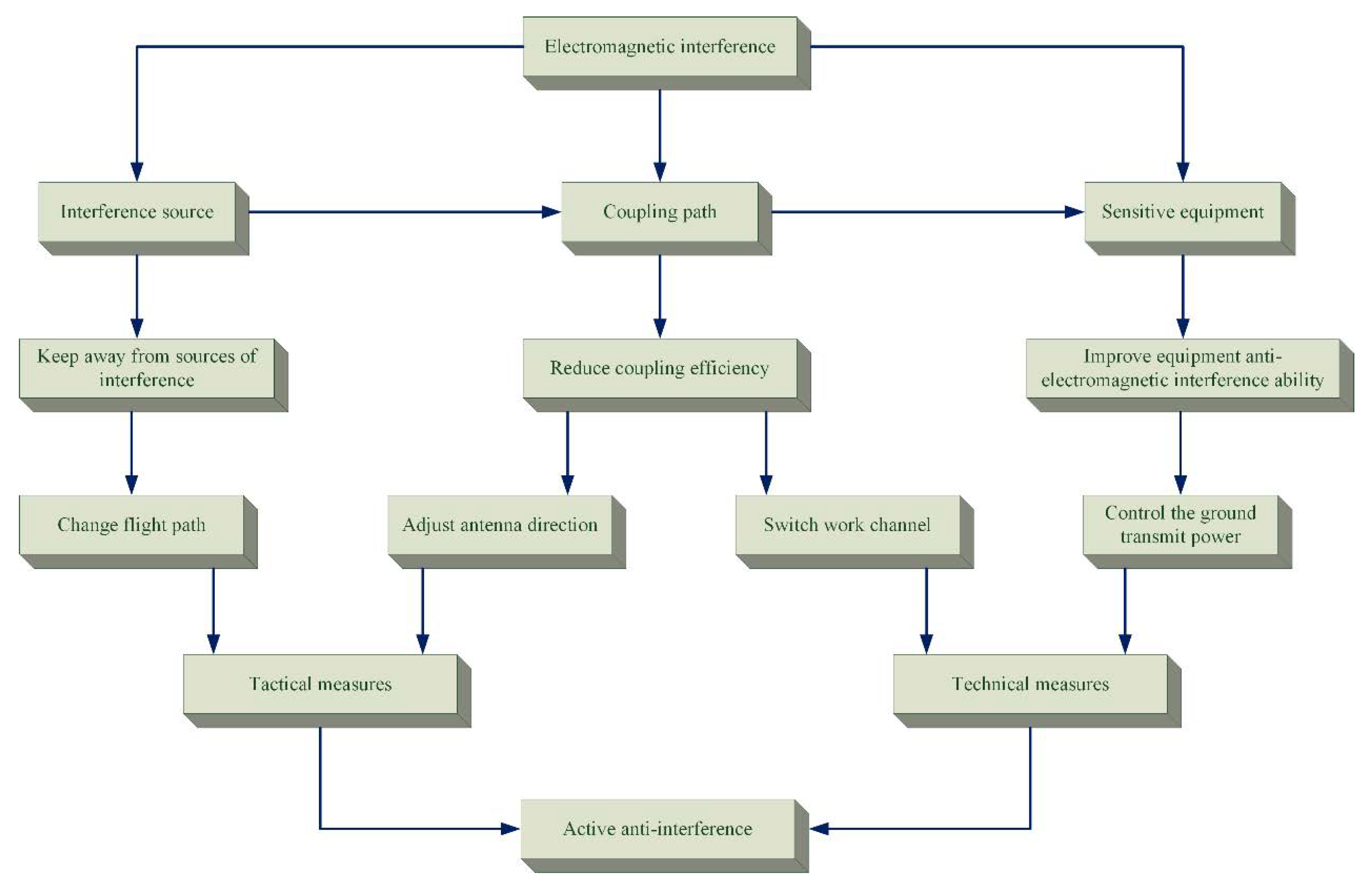
4. Method for UAV Electromagnetic Interference Suppression

Typical UAV electric signal path comprises a power circuit and a signal loop (Figure 4).
Electromagnetic interference is mainly caused by three elements: the source of interference, the way of interference, and the device being interfered with. Through the analysis of the working environment of the electric power inspection drone, it is known that strong electromagnetic fields are distributed around the wires of UHV transmission lines, and the strong electromagnetic waves emitted by them are the main interference source. The electronic devices that are susceptible to interference in UAV systems mainly include flight control systems, various measurement modules (IMU, GPS locator, barometer, magnetic compass, etc.) and signal receivers. Therefore, the core of the design of anti-electromagnetic interference schemes for UAVs mainly lies in how to protect these easily interfered devices [40].

4.1. Anti-Electromagnetic Interference Method of UAV Data Link

The UAV data link needs to face the electromagnetic interference caused by the converter station during operation, as well as the multipath fading, power attenuation and Doppler shift caused by high-speed movement due to the surrounding complex environment. Research on anti-jamming technologies applied to UAV data links are mainly divided into three categories: related technologies to improve system reliability and effectiveness, cooperative communication technologies and anti-jamming technologies based on cognitive radio.

4.1.1. Anti-Jamming Technology to Improve Communication Reliability

Literature [41] proposes a variable rate MIMO scheme that can be applied to UAVs to overcome the interference caused by scattering and obstacles and improve the reliability of communication. The literature [42] systematically analyzed the capacity of the airborne multiple-input multiple-output (MIMO) wireless communication system, and determined the maximum achievable capacity of the system, which further derived the airborne MIMO communication system in any given 3D transceiver A necessary and sufficient condition for reaching the upper limit of the capacity under the antenna array geometry. This research helps to select UAV communication system parameters more reasonably and design an airborne MIMO communication system that achieves the best performance in system capacity. The literature [41,42] focuses on the performance evaluation of MIMO systems used in UAV communication. Literature [41] starts from the communication algorithm to improve the anti-interference ability. Literature [42] obtained the relationship between the UAV MIMO communication system and the 3D transceiver array antenna structure through a large amount of data fitting, and provided a basis for designing a communication system with more anti-interference ability.
The research on anti-jamming technology to improve communication reliability mainly focuses on the physical layer and link layer (Table 4).
Literature [48] studies the networking of drones. This paper compares a variety of different communication architectures used in UAV networking, and explores the self-organizing network capabilities of UAV ad hoc networks based on the IP protocol. Literature [49] puts forward a plan to integrate airborne networks with other heterogeneous wireless communication systems through field measurements, and studies the communication stability of the UAV data link system when integrated with other wireless communication systems.
Literature [50] proposed a simulation model suitable for the analysis of air–ground hybrid system, and studied the influence of UAV height and maneuverability on communication range and channel capacity. Literature [51] analyzes the UAV-to-ground link of a small quadrotor UAV network based on 802.11a through a series of field experiments. The influence of the antenna azimuth on the received signal strength and UDP throughput performance of the UAV at different altitudes, yaw angles and distances is given.
These studies have proposed different methods to improve the communication reliability of the UAV data link system from the perspectives of coding, self-organizing networks, and heterogeneous network integration, and provided a reference for the anti-electromagnetic interference scheme of the data link of the patrol drone.

4.1.2. Anti-Electromagnetic Interference Technology Based on Cooperative Communication

In addition to improving the stability of the UAV network itself, there is also a class of anti-electromagnetic interference methods developed based on cooperative communication.
One direction is single-machine multi-domain collaboration. Literature [52] proposes a cooperative communication method under the condition of multiple sources. The simulation results show that the scheme reduces the bit error rate of the received signal, and the transmission reliability is higher under the condition of the dynamic transmission rate. The research of multi-source cooperative communication has pointed out the direction for multi-link cooperative information transmission of the UAV data link. The literature [52,53] proposed an asynchronous cooperative information transmission method on the basis of cooperative communication, from the physical layer (constructing the asynchronous cooperative transmission mode of three-dimensional space) and the link layer (through the multi-link cooperative forwarding protocol). Enhance the reliability of information transmission. The former makes full use of the three spatial diversity technologies at the physical layer to increase the diversity gain and greatly enhance the anti-interference ability. The latter at the link layer eliminates the impact of short-term changes in the link through single-transmit and multiple-receive and a bootstrap response algorithm based on a random synchronization contention window, resulting in better network arrival rate and energy efficiency, and enhanced transmission reliability. Improved anti-interference ability. Literature [54] proposes a cooperative communication relay selection method under the outdated channel state information generated by the relative movement of the receiver and transmitter or when the environment changes rapidly. Choosing the optimal relay can be resisted to a certain extent. Interference to cooperative communication systems. Literature [55] proposes a channel state information prediction technology based on MAP criteria to improve the anti-interference ability of cooperative communication systems.
The other direction is multi-machine coordination. One of the advantages of Ad hoc networks commonly used in drone clusters is the system’s robustness. The UAV cluster system will not be unable to operate normally due to communication interference of one or several UAVs. In addition, some researchers have further enhanced this property by improving the algorithm of Ad hoc networks. In reference to the problem of power optimization control in the multi-channel case, the literature [56] proposed a non-cooperative game distributed power control method based on the influence of the importance of multi-cluster network nodes of UAVs. Each node evaluates the importance factor of the entire network node based on the connectivity information. This algorithm can converge quickly and ensure the interference tolerance of important nodes such as cluster heads and core nodes.

4.1.3. Anti-Jamming Technology Based on Cognitive Radio

The research on anti-jamming technology based on cognitive radio focuses on solving the problems of the shortage of spectrum resources and the increasing difficulty of user spectrum management, and considers applying the cognitive radio technology of spectrum sensing and system reconfiguration to drones [57,58,59,60,61].
Aiming at the degree of interference of UAV data link in a complex environment composed of geographic environment, meteorological environment, electromagnetic environment, etc., the literature [62] proposes a prediction and evaluation method combining support vector machines and power criteria. The predicted results of this method can be used to reconstruct the UAV data link. Literature [63] proposes a UAV data link communication system based on cognitive radio technology. The author designed a cognitive engine that takes the signal-to-noise ratio, channel estimation result, spectrum sensing result, Doppler frequency shift, etc. as input. Through the designed cognitive engine, it outputs the reconstructed communication parameters of the UAV system and the Enter to determine the type of situation encountered by the system. Literature [64] based on the analysis of the current UAV data link problems, the concept of the UAV smart data link based on a cognitive radio is proposed, and the working process of the UAV smart data link is described. Index system and function classification of human–machine intelligent data link. On the basis of determining the function of the UAV data link, the architecture of the UAV intelligent data link is proposed. Literature [65] proposes a multi-parameter planning method for UAV data link based on a state machine, which provides a feasible and effective idea for UAV data link reconstruction.

4.1.4. UAV Electromagnetic Interference Adaptive Scheme

There are many studies that comprehensively adopt a variety of anti-interference technologies to propose an overall solution for UAV data link anti-electromagnetic interference, which has a high reference value for UAV electromagnetic compatibility issues in the converter station scenario.
Traditional anti-jamming methods of UAV data link are mainly implemented from the perspective of spread spectrum and coding, but the room for improvement of anti-jamming performance is limited and the technical bottleneck is high. Take frequency hopping communication as an example: Although the frequency hopping map has flexible and changeable random characteristics, the lack of autonomous perception will cause the operating frequency to fall into the broadband interference interval, affecting the normal operation of the data link. In addition, traditional power control methods mainly reduce the influence of electromagnetic interference on the crosstalk between data link codes by selecting power gears. This method relies too much on experience accumulation and has poor adjustability [66].
The literature [67] proposed a new method for UAV data link electromagnetic interference adaptation based on electromagnetic environment perception, which uses airborne antennas and UAV telemetry links to achieve key frequency band monitoring and measurement information return. Correlation vector machine regression dynamic data link electromagnetic interference effect threshold prediction model and UAV data electromagnetic interference level judgment method, and finally a set of relatively complete and enlightening adaptive implementation method of UAV data link electromagnetic interference is proposed (Figure 5).

4.2. Anti-Electromagnetic Interference Method for UAV Hardware Equipment

There are two ways to interfere with the power inspection UAV system: radiation coupling and conduction coupling. Radiation coupling means that electromagnetic waves enter the cabin through the ventilation and heat dissipation windows on the drone body and equipment shell, line interfaces and connection gaps, or electromagnetic coupling between airborne electronic equipment, which causes interference to electronic equipment and circuits. Conduction coupling means that electromagnetic waves induce a current in other equipment such as airborne antennas or external circuits, and conduct them along the power supply and signal circuits, causing logic errors in key equipment and even hardware damage. According to the above interference methods, shielding and filtering methods are mainly adopted for protection on electric power inspection drones [68].

4.2.1. Shield

The shielding technology of electromagnetic waves mainly uses insulating materials to block electromagnetic wave interference [69]. In actual use, shielding technology can only slightly reduce electromagnetic waves through absorption and reflection, but cannot effectively block them.
In traditional electromagnetic shielding, components made of conductive materials or ferromagnetic materials are commonly used to shield and isolate the protected objects to control the induction and radiation of electric fields, magnetic fields and electromagnetic waves from one area to another. However, due to the lightweight requirements of drones, conventional shielding materials (copper, iron, aluminum and other metals) are basically not used to make drone shells.
Currently, UAV shell parts generally use engineering plastics or carbon fiber composite materials. Engineering plastic does not have much protection against electromagnetic interference. However, some researchers have applied a metal layer [70] or other electromagnetic wave shielding coatings [71] on the engineering plastic shell to turn the processed engineering plastic shell into a Faraday cover to achieve a certain anti-electromagnetic interference effect. This approach is simple to operate and design, and the production cost is generally low, but there are corresponding shortcomings. For example, coating scratches may cause shielding failure. During thermal cycling, the coating may decompose due to heat and cause other coating adhesion problems. It may be necessary to add additional protective surfaces to avoid coating oxidation. Therefore, some researchers have turned their attention to developing carbon fiber composite materials with electromagnetic shielding properties [72,73,74,75].
Without adding special parts inside the drone, use appropriate insulating materials to fill all the gaps in the drone to prevent electromagnetic waves from entering. These filling materials include wire mesh pads, conductive cloth pads, soft metals, etc. [76]. Adding a shielding layer near the electronic components can also reduce electromagnetic interference. For example, use tin foil for the whole package, and use shielded twisted pair in the signal circuit [17].
You can also reduce the impact of electromagnetic interference by optimizing the design of the drone. For example, keep the key components of the drone, the flight control system, and the measurement system away from the interface and the gap, so as to weaken the electromagnetic waves in these parts. Separate the instrument cord from the power cord as much as possible. If it must pass, cross it at 90 [77].

4.2.2. Filter

Filtering is a method of removing interference signals. Filtering refers to the technology to filter out the electromagnetic interference energy in the conduction coupling and maintain the working level in the line. For the energy coupled in from the antenna part, a band-pass filter can be used at the external interface such as the antenna to filter and match the received signal. For energy coupled in from external lines, power filters can be used. To improve the high-frequency interference signal, the commonly used electromagnetic interference filter is the ferrite magnetic ring filter [78]. According to the frequency of interference suppression, choose ferrite materials with different permeability. The higher the permeability of the ring magnet, the greater the impedance at low frequencies and the smaller the impedance at high frequencies. The ferrite bead can be regarded as a resistance whose resistance changes with frequency. According to the characteristics of electromagnetic wave frequency, nickel-zinc ferrite or manganese-zinc ferrite can be selected. The high-frequency characteristics of the former are better than the latter. The higher the magnetic permeability of ferrite, the greater the impedance at low frequencies and the smaller the impedance at high frequencies. Therefore, when suppressing high-frequency interference, nickel–zinc ferrite should be used. Otherwise, use manganese–zinc ferrite. It is also possible to put manganese-zinc and nickel-zinc ferrite on the same bundle of lines at the same time, so that the interference frequency band that can be suppressed is wider. The greater the difference between the inner and outer diameters of the magnetic ring and the greater the longitudinal height, the greater the impedance, but the inner diameter of the magnetic ring must be tightly packed to avoid magnetic leakage. The installation position of the magnetic ring should be as close as possible to the interference source or the interface [69].

5. Conclusions

Unmanned equipment such as drones are suitable for use in a variety of scenarios, but the reliance on unmanned equipment on wireless networks and the susceptibility of wireless networks to interference from the external environment also bring a lot of inconvenience to the application of these devices. The purpose of this paper is to take the interference of the electromagnetic environment of the converter station in the HVDC transmission system on the inspection drone as an example to discuss the feasible methods of the drone to suppress the interference of the complex electromagnetic environment.
To the best of our knowledge, there is no analysis of the anti-electromagnetic interference of the UAV for inspection of converter equipment in the previous research. On the basis of analyzing the characteristics of the converter equipment and the communication characteristics of the UAV, this article focuses on the analysis of the hardware optimization scheme with shielding and filtering as the main anti-jamming means. This anti-interference method is quite universal and can be used in various broadband electromagnetic interference environments. It can deal with the interference of different magnitudes by using different materials and specifications. The quantitative research here involves a huge amount of space, so this article will not start the argumentation. It can be used as a feasible research direction to provide evidence for follow-up research on this basis.
In addition, the application effects of UAV communication signal multipath fading and corresponding modulation technology in the environment where the converter equipment outputs broadband interference need to be further analyzed, explored and compared.

Author Contributions

Conceptualization, Y.L. and Q.D.; methodology, K.L.; software, Y.L.; validation, Y.L., K.L. and Q.D.; formal analysis, K.L. and Y.L.; investigation, Y.L. and K.L.; resources, Q.D.; data curation, Y.L.; writing—original draft preparation, Y.L. and K.L.; writing—review and editing, Y.L. and S.V.; visualization, Y.L.; supervision, Q.D. and S.L.; project administration, Q.D. and S.L.; funding acquisition, Q.D. and L.Y. All authors have read and agreed to the published version of the manuscript.

Funding

This work was supported by National Natural Science Foundation of China (Grant Nos. 11872148, U1908217, 61801034).

Conflicts of Interest

The researcher claims no conflict of interests.

References

  1. Chen, W. Principles of Mobile Communication; Tsinghua University Press: Beijing, China, 2016. [Google Scholar]
  2. Zhang, L. Discussion on Influence of 110–220 kV Power Transmission and Transformation Facility on Electromagnetic Environment. Electr. Equip. 2008, 9, 56–58. [Google Scholar]
  3. Ma, W.; Nie, D.; Wan, B.; Zhang, X.; Xie, H. Characteristics of Electromagnetic Disturbance in HVDC Valve Hall. High Volt. Eng. 2008, 34, 1317–1323. [Google Scholar]
  4. Liu, L. Exploration on the influence of electromagnetic radiation on environment of Sanming Fuxing 220 kV substation expansion project. Straits Sci. 2020, 4, 50–52. [Google Scholar]
  5. Dong, D. Electromagnetic Disturbance of ±500 kV Converter Valve. Master’s Thesis, South China University of Technology, Guangzhou, China, 2012. [Google Scholar]
  6. Don’t “Despike” Your Signal Lines, Add a Resistor Instead. Available online: http://massmind.org/techref/electips.htm (accessed on 21 January 2014).
  7. Jiao, Y.; Hou, D.; Zhou, D.; Hu, T.; Lin, J.; Wang, Z. Efficiency evaluation of unmanned aerial vehicle in complex electromagnetic environment. Simul. Dyn. Electromagn. Interf. Environ. Unmanned Aer. Veh. Data Link 2014, 26, 136–141. [Google Scholar]
  8. Xuan, Y.; Tian, X.; Cheng, D.; Ju, X.; Wang, W. Analysis of the Battle Field Electromagnetic Interference on Unmanned Aerial Vehicle System. Equip. Environ. Eng. 2008, 1, 99–102. [Google Scholar]
  9. Sun, H.; Cui, X.; Du, L. Electromagnetic Interference Prediction of ± 800 kV UHVDC Converter Station. IEEE Trans. Magn. 2016, 52, 9400404. [Google Scholar] [CrossRef]
  10. Yang, W.; Wen, Y.; Meng, S.; Wang, J. Telemetry Performance Analysis of DS/FH Hybrid Spread Spectrum Signal. Telecommun. Eng. 2009, 49, 13–17. [Google Scholar]
  11. Kasten, D.G.; Caldecott, R.; Sebo, S.A.; Liu, Y. A computer program for HVDC converter station RF noise calculations. IEEE Trans. Power Deliv. 1994, 9, 750–756. [Google Scholar] [CrossRef]
  12. Kasten, D.G.; Liu, Y.; Caldecott, R.; Sebo, S.A. Radio frequency performance analysis of high voltage DC converter stations. In Proceedings of the 2001 IEEE Porto Power Tech Proceedings (Cat. No.01EX502), Porto, Portugal, 10–13 September 2001; IEEE: New York, NY, USA, 2001. [Google Scholar]
  13. Zhao, Z.; Cui, X.; Wang, Q. Analysis of Electromagnetic Disturbance from Valve Hall in Convert Station. High Volt. Eng. 2010, 3, 643–648. [Google Scholar]
  14. Xu, Z. Electromagnetic Compatibility Research of UHVDC Converter Station. Master’s Thesis, Guangxi University, Nanning, China, 2016. [Google Scholar]
  15. Qinghai-Henan ±800 kV UHV DC Transmission Project Energized. Available online: https://electricenergyonline.com/article/energy/category/t-d/56/848885/qinghai-henan-800kv-uhv-dc-transmission-project-energized.html (accessed on 12 August 2020).
  16. Li, B. Research on Some Key Problems in the Software Platform of UAV EMC Expert System. Ph.D. Thesis, Nanjing University of Aeronautics and Astronautics, Nanjing, China, 2009. [Google Scholar]
  17. Zhang, D.; Chen, Y.; Cheng, E. Research on Dynamic Electromagnetic Susceptibility for Electromagnetic Interference Prediction of UAV Information Link. High Volt. Eng. 2019, 45, 665–672. [Google Scholar]
  18. Bekmezci, I.; Ozgur, K.S.; Şamil, T. Flying ad-hoc networks (FANETs): A survey. Ad Hoc Netw. 2013, 11, 1254–1270. [Google Scholar] [CrossRef]
  19. Zhang, Z.; Zhao, Z.; Yao, C. A Hardware-in-Loop Simulation System for UAV Communication and Jamming Electromagnetic Environment. Telecommun. Eng. 2019, 59, 476–481. [Google Scholar]
  20. Kong, X.; Chen, W. Reliability Research of UAV Communication System in Complex Electromagnetic Environment. J. Artill. Acad. 2007, 27, 38–40. [Google Scholar]
  21. Namuduri, K. UAV Networks and Communications; Cambridge University Press: Cambridge, UK, 2017. [Google Scholar]
  22. Hu, G.; Zhu, S.; Xie, B. Fractal Brownian Motion Model of Multipath Fading Channels. Acta Electron. Sin. 2003, 31, 8–12. [Google Scholar]
  23. Zhang, D.; Cheng, E.; Wan, H.; Zhou, X.; Chen, Y. Prediction of Electromagnetic Compatibility for Dynamic Datalink of UAV. IEEE Trans. Electromagn. Compat. 2019, 61, 1474–1482. [Google Scholar] [CrossRef]
  24. Xu, L. Study on Test Method of Long Stator Linear Synchronous Motor. Master’s Thesis, Zhejiang University, Hangzhou, China, 2007. [Google Scholar]
  25. Yang, Z. Hazards of electromagnetic interference and EMC design. Auto Time 2015, 9, 88–91. [Google Scholar]
  26. Qian, Z.; Chen, H. State of Art of Electromagnetic Compatibility Research on Power Electronic Equipment. Trans. China Electrotech. Soc. 2007, 22, 1–11. [Google Scholar]
  27. Qi, C. Research on the Application of Wireless Sensor Network Based on ZigBee in Monitoring System. Master’s Thesis, Wuhan University of Technology, Wuhan, China, 2014. [Google Scholar]
  28. Li, H. Inspection of Radiation Disturbance and Radiation Immunity of UAV. Master’s Thesis, Heilongjiang University, Harbin, China, 2017. [Google Scholar]
  29. Wang, J.; He, W. Relationship between the Electric Field on the Surface of Insulators and Ultra-Violet Pulse Intensity and Its Application in Detecting Faulty Insulators. Trans. China Electrotech. Soc. 2008, 23, 137–142. [Google Scholar]
  30. Meng, X. Research on Electromagnetic Wave Monitoring Technology of Insulator Discharge in Transmission Line. Master’s Thesis, North China Electric Power University, Beijing, China, 2007. [Google Scholar]
  31. Tang, Z. Design and Simulation of UAVs Power Patrol System. Master’s Thesis, Guangdong University of Technology, Guangzhou, China, 2017. [Google Scholar]
  32. Liu, S.; Zhu, L. Research on Long-range Detection Technology for Corona Discharge Radiation Signal. High Volt. Eng. 2013, 39, 2845–2851. [Google Scholar]
  33. Chen, A.; Chen, C. Co-channel Interference and its Restraining Measures in Co-frequency Simulcast Systems. Telecommun. Eng. 2009, 49, 18–22. [Google Scholar]
  34. Qiao, Z.; Pan, X.; He, Y. Damage of high power electromagnetic pulse to unmanned aerial vehicles. High Power Laser Part. Beams 2017, 29, 61–66. [Google Scholar]
  35. Wu, R.; Zhang, H.; Zhong, T. Research on high power microwave weapon against UAV. Aerodyn. Missile J. 2015, 11, 36–39. [Google Scholar]
  36. Zhang, J.; He, Y.; Pan, X. Vulnerability Analysis of UAV Against Mesoband Electromagnetic Pulse. J. Proj. Rocket. Missiles Guid. 2020, 40, 110–115. [Google Scholar]
  37. Liu, P.; Ding, L. Electromagnetic Environmental Effects; Zhang, L., Ed.; Science Press: Beijing, China, 2018; pp. 20–24. [Google Scholar]
  38. Taylor, C.D.; Satterwhite, R.S.; Charles, W.H. The Response of Terminated Two-Wire Transmission Line Excited by Nonuniform Electromagnetic Field; Sandia Corporation: Albuquerque, NM, USA, 1965. [Google Scholar]
  39. Sun, Y.; Li, L.; Wang, W. Discussion on the Safety Engineering of UAV in UHV Transmission Line Routing Inspection. Shandong Electr. Power 2017, 44, 15–19. [Google Scholar]
  40. Zhang, X.; Wang, X.; Wei, Y. Research of Security Strategy of UAV Board Data link. Comput. Secur. 2008, 3, 62–64. [Google Scholar]
  41. Gans, M.J.; Borle, K.M.; Chen, B.; Freeland, T.; McCarthy, D.; Nelson, R.; Oleski, P. Enhancing connectivity of unmanned vehicles through MIMO communications. In Proceedings of the 2013 IEEE 78th Vehicular Technology Conference: VTC2013-Fall, Las Vegas, NV, USA, 2–5 September 2013; IEEE: New York, NY, USA, 2013. [Google Scholar]
  42. Su, W.; Matyjas, J.D.; Gans, M.J.; Batalama, S. Maximum achievable capacity in airborne MIMO communications with arbitrary alignments of Linear transceiver antenna arrays. IEEE Trans. Wirel. Commun. 2013, 12, 5584–5593. [Google Scholar] [CrossRef]
  43. Wang, P. Design of Key Blocks of a High Speed DS/FH Communication System for UAVs. J. Spacecr. TT&C Technol. 2016, 49, 41–44. [Google Scholar]
  44. Ding, D.; Liu, M. Realization of a High Efficient Anti-jamming UAV TT&C Channel. Telecommun. Eng. 2009, 49, 41–44. [Google Scholar]
  45. Guo, S.; Guo, D.; Zhang, Q.; Wu, N.; Deng, J. Research Progress of Anti-jamming Technology of Unmanned Aerial Vehicle (UAV) Data Link. In Proceedings of the 2020 the 3rd International Conference on Aeronautical, Aerospace and Mechanical Engineering (AAME 2020), Sanya, China, 16–18 February 2020; IOP: Bristol, UK, 2020. [Google Scholar]
  46. He, Y.; Zhai, D.; Zhang, R.; Du, X.; Guizani, M. An Anti-Interference Scheme for UAV Data Links in Air-Ground Integrated Vehicular Networks. Sensors 2019, 19, 4742. [Google Scholar] [CrossRef] [Green Version]
  47. Qing, L. Non-cooperative Game Power Control in Swarm UAV Networks. Telecommun. Eng. 2019, 59, 786–791. [Google Scholar]
  48. Li, J.; Zhou, Y.; Lamont, L. Communication architectures and protocols for networking unmanned aerial vehicles. In Proceedings of the 2013 IEEE Globecom Workshops (GC Wkshps), Atlanta, GA, USA, 9–13 December 2013; IEEE: New York, NY, USA, 2013. [Google Scholar]
  49. Cheng, B.N.; Charland, R.; Christensen, P.; Veytser, L.; Wheeler, J. Evaluation of a multihop airborne IP backbone with heterogeneous radio technologies. IEEE Trans. Mob. Comput. 2014, 13, 299–310. [Google Scholar] [CrossRef]
  50. Gomez, K.; Rasheed, T.; Reynaud, L.; Kandeepan, S. On the performance of aerial LTE base-stations for public safety and emergency recovery. In Proceedings of the 2013 IEEE Globecom Workshops (GC Wkshps), Atlanta, GA, USA, 9–13 December 2013; IEEE: New York, NY, USA, 2013. [Google Scholar]
  51. Yanmaz, E.; Kuschnig, R.; Bettstetter, C. Channel measurements over 802. 11a-based UAV-to-ground links. In Proceedings of the 2011 IEEE GLOBECOM Workshops (GC Wkshps), Houston, TX, USA, 5–9 December 2011; IEEE: New York, NY, USA, 2011. [Google Scholar]
  52. Ribeiro, A.; Wang, R.; Giannakis, G.B. Multi-source cooperation with full-diversity spectral-efficiency and controllable-complexity. IEEE J. Sel. Areas Commun. 2007, 25, 415–425. [Google Scholar] [CrossRef]
  53. Ribeiro, A.; Sidiropoulos, N.D.; Giannakis, G.B.; Yu, Y. Achieving wireline random access throughput in wireless networking via user cooperation. IEEE Trans. Inf. Theory 2007, 53, 732–758. [Google Scholar] [CrossRef]
  54. Fei, L.; Gao, Q.; Zhang, J.; Xu, Q. Relay selection with outdated channel state information in cooperative communication systems. IET Commun. 2013, 7, 1557–1565. [Google Scholar] [CrossRef]
  55. Fei, L.; Zhang, J.; Gao, Q.; Peng, X.H. Outage-optimal relay strategy under outdated channel state information in decode-and-forward cooperative communication systems. IET Commun. 2015, 9, 441–450. [Google Scholar] [CrossRef]
  56. Introduction of RTP EMI Shielding Material Properties. Available online: http://web.rtpcompany.com/cn/products/shielding/control.htm (accessed on 5 March 2021).
  57. Radio Frequency Interference at the Geostationary Orbit. Available online: https://ntrs.nasa.gov/api/citations/19810018807/downloads/19810018807.pdf (accessed on 15 June 1981).
  58. Radio Frequency Interference—And What to Do About It. Available online: http://www.radiosky.com/journal0901.html (accessed on 21 January 2014).
  59. Lab Note #103 Snubbers—Are They Arc Suppressors. Available online: https://arcsuppressiontechnologies.com/images/1_LN103rvC.pdf (accessed on 5 February 2012).
  60. Lab Note #105 EMI Reduction—Unsuppressed vs. Suppressed. Available online: https://www.arcsuppressiontechnologies.com/wp-content/uploads/2016/07/Arc_Supression_Lab_Note_105_Contact_Life.pdf (accessed on 5 February 2012).
  61. Integrated Circuit EMC. Available online: https://cecas.clemson.edu/cvel/emc/ic_emc/ic.html (accessed on 21 January 2014).
  62. Zhang, W.; Ding, W.; Liu, C. Prediction of interference effect on UAV data link in complex environment. Syst. Eng. Electron. 2016, 38, 760–766. [Google Scholar]
  63. Reyes, H.; Gellerman, N.; Kaabouch, N. A cognitive radio system for improving the reliability and security of UAS/UAV networks. In Proceedings of the 2015 IEEE Aerospace Conference, Big Sky, MT, USA, 7–14 March 2015; IEEE: New York, NY, USA, 2015. [Google Scholar]
  64. Chen, Z.; Jiang, T.; Fan, J. Architecture of UAV Intelligent Data Link System. Radio Eng. China 2009, 39, 4–6. [Google Scholar]
  65. Huang, W.; Ding, W.; Liu, C. Multi-parametric programming approach for data link of UAS based on state machine. In Proceedings of the 2015 International Conference on Industrial Informatics—Computing Technology, Intelligent Technology, Industrial Information Integration (ICIICII), Wuhan, China, 3–4 December 2015; IEEE: New York, NY, USA, 2015. [Google Scholar]
  66. Liu, Y.; Piao, H.; Xiao, L. An Overview of Anti-Interference Techniques for UCAV Data Link. Aircr. Des. 2017, 36, 13–16. [Google Scholar]
  67. Zhang, D.; Chen, Y.; Cheng, E. A New Method for UAV’s Datalink Adaptive to EMI. Trans. Beijing Inst. Technol. 2020, 40, 880–887. [Google Scholar]
  68. Zhang, D.; Chen, Y.; Cheng, E. Effects of Electromagnetic Interference (EMI) on Information Link of UAV. Trans. Beijing Inst. Technol. 2019, 39, 756–762. [Google Scholar]
  69. Huang, B.; Zhang, G.; Wan, X. Research on Anti Electromagnetic Interference Method in the Power Series Compensation Device of UAV Inspection. North China Electr. Power 2016, 5, 44–48. [Google Scholar]
  70. Alcohol-Soluble Electromagnetic Wave Shielding Coating. Available online: https://patents.google.com/patent/CN101880499B/zh (accessed on 22 April 2010).
  71. Chung, D.D.L. Carbon materials for structural self-sensing, electromagnetic shielding and thermal interfacing. Carbon 2012, 50, 3342–3353. [Google Scholar] [CrossRef]
  72. Chen, L.; Yin, X.; Fan, X.; Chen, M.; Ma, X.; Cheng, L.; Zhang, L. Mechanical and electromagnetic shielding properties of carbon fiber reinforced silicon carbide matrix composites. Carbon 2015, 95, 10–19. [Google Scholar] [CrossRef]
  73. Zhan, Y.; Long, Z.; Wan, X.; Zhang, J.; He, S.; He, Y. 3D carbon fiber mats/nano-Fe3O4 hybrid material with high electromagnetic shielding performance. Appl. Surf. Sci. 2018, 444, 710–720. [Google Scholar] [CrossRef]
  74. Jia, Y.; Li, K.; Xue, L.; Ren, J.; Zhang, S.; Li, H. Mechanical and electromagnetic shielding performance of carbon fiber reinforced multilayered (PyC-SiC) n matrix composites. Carbon 2017, 111, 299–308. [Google Scholar] [CrossRef]
  75. Tanabe, S.; Murata, Y.; Chishaki, H.; Shimato, T. 3D-MoM analysis of radio frequency noise radiation from HVDC converter station. In Proceedings of the Power Conversion Conference-Osaka 2002 (Cat. No.02TH8579), Osaka, Japan, 2–5 April 2002; IEEE: New York, NY, USA, 2002. [Google Scholar]
  76. Zhang, D.; Chen, Y.; Xiao, X. Analysis of Mechanism of Electromagnetic Interference on UAV’s Main Telecontrol System. J. Microwaves 2016, 32, 94–100. [Google Scholar]
  77. Jiang, A.; Chen, M.; Huang, X. Discussion on anti-electromagnetic interference technology and solution. A & S 2012, 9, 150–151. [Google Scholar]
  78. Chen, Y.; Zhang, D.; Cheng, E.; Wang, X. Investigation on susceptibility of UAV to radiated IEMI. In Proceedings of the 2018 IEEE International Symposium on Electromagnetic Compatibility and 2018 IEEE Asia-Pacific Symposium on Electromagnetic Compatibility (EMC/APEMC)Electromagnetic Compatibility (EMC/APEMC), Singapore, 14–18 May 2018; IEEE: New York, NY, USA, 2018. [Google Scholar]
Figure 1. Schematic diagrams of converter valve(s), 6 pulse converters and 12 pulse-converters.
Electronics 10 00701 g001
Figure 2. Schematic diagram of valve hall [15].
Electronics 10 00701 g002
Figure 3. Continuous wave electromagnetic radiation effect test system for UAV.
Electronics 10 00701 g003
Figure 4. UAV power circuit and signal circuit [39].
Electronics 10 00701 g004
Figure 5. UAV data link electromagnetic interference adaptive process.
Electronics 10 00701 g005
Table 1. The sources of UAV electromagnetic interference and coupling methods.
Source of Electromagnetic InterferenceElectromagnetic Coupling Approach
In the systemUAV power ignition devicePower port
Airborne measurement and control launch equipmentDigital signal port
Low frequency analog signal port
Radio frequency port
Actuating device and equipment with large current changes and intermittent contactsPower port
High current inverter power supply and switching power supplyPower port
High-IF digital circuit and mission load with similar circuit structure and radio transmissionDigital signal port
Radio frequency port
Out of the systemNatural electromagnetic phenomenon (high altitude)Atmospheric noise
Cosmic radiation
Man-made electromagnetic phenomena (low altitude)Various electromagnetic fields intentionally generated by radio transmitters, and additional electromagnetic fields generated by these transmitters and other technical equipment
Table 2. Modules and functions of UAV continuous wave electromagnetic radiation effect test system.
ModuleFunction
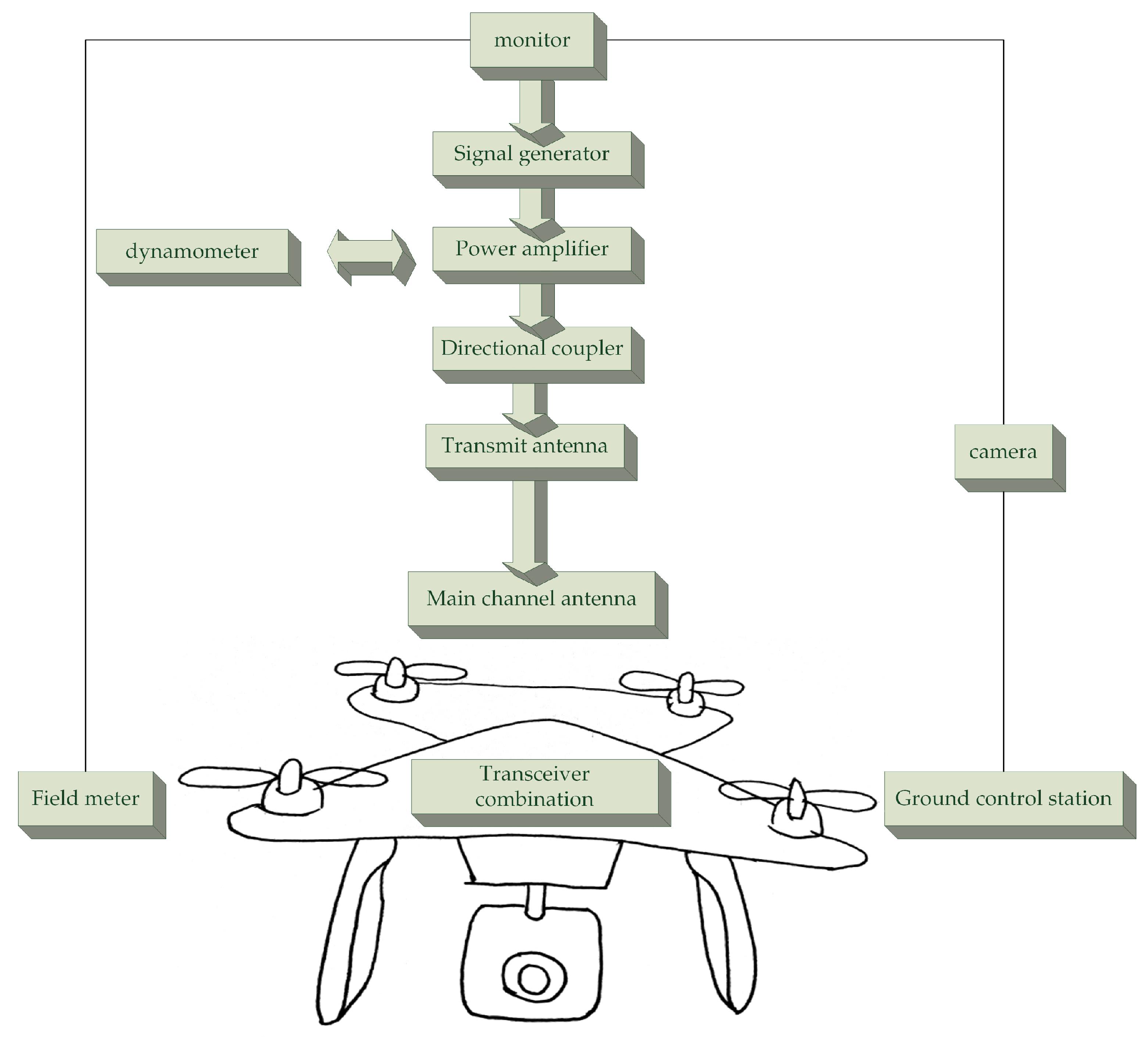
Continuous wave radiation emission systemLaunch an electromagnetic wave with adjustable parameters to the subject to radiatly interfere with the UAV data link
Subject (the tested UAV)Place in an open area during normal work, and check the working status under interference
Dynamic monitoring systemMonitor the ground control station’s telemetry display window to report information, and use the “lost lock” phenomenon as the evaluation criterion for continuous wave electromagnetic interference on the data link. The loss of the main uplink channel means that the ground control station cannot send control commands to the drone and the aircraft is out of control, If the downlink telemetry link loses lock at this time, the drone will completely disappear from the ground control station’s “view”
Table 3. Electromagnetic pulse damage classification of electronic components.
Damage ModeDamage ProcessDamage Result
instantaneous interferenceThe low coupling power is equivalent to adding noise or interference signals to the system.Affect the normal operation of electronic components.
high voltage breakdownThe electromagnetic energy coupled into the electronic components is converted into high voltage and high current.Electrical breakdown occurred in electronic components.
device burnoutPneumatic heating causes the component surface temperature to rise sharply, and the surface material produces a series of complex physical and chemical changes.Ablation of semiconductor devices or fusing of wires, etc.
microwave heatingThe electromagnetic pulse heats the device temperature to exceed the temperature limit of normal operation.The device is malfunctioning.
Table 4. Some typical anti-electromagnetic interference research directions.
The Research DirectionNetwork Layer
Integration and performance evaluation of low-power MIMO systems [32,33].Physical layer
Research and application of anti-jamming technology represented by spread spectrum and frequency hopping technology [43,44,45,46,47].Link layer
Under the limitation of limited spectrum resources, design high-throughput, high-reliability physical layer and MAC layer protocols and strategies [34,35].Physical layer
Integration of UAV data link system and satellite communication system, as well as other wireless communication systems [36,37].Physical layer
Publisher’s Note: MDPI stays neutral with regard to jurisdictional claims in published maps and institutional affiliations.

