1. Introduction
To support the “carbon emission peak in 2030 and carbon neutrality in 2060” goal of China, photovoltaic wind power and other new energy power generations will grow explosively as the energy supply system is changing from coal to diversification [
1,
2]. The total installed capacity of photovoltaic and wind power in China reaches 252 GW in 2020 and is expected to reach 1.2 billion kilowatts by 2030, in an effort to peak CO
2 emissions by 2030. On the one hand, as long-distance transmission lines and multiple transformers are mostly used in new energy grid-connected power generation systems to connect power sources and the utility grid, the system short-circuit impedance increases as the penetration of new energy generation increases. On the other hand, the new energy power generation converter mainly adopts a grid voltage orientated current-controlled algorithm based on a phase-locked loop (PLL), which does not have voltage and frequency support ability. With the increase in new energy generation penetration, the proportion of a synchronous generator in the grid decreases, and the equivalent inertia of the system also decreases. As a result, the reform of energy system leads to the gradual transition from a traditional power grid dominated by synchronous generator sets to a weak grid with high penetration of new energy and power electronics, and is characterized by “low inertia and low short circuit ratio”, which brings critical challenges to system safety and stable operation [
3,
4]. In September 2015, an overvoltage fault occurred in the transmission end of a JinSu ultra-high voltage direct current system in East China, and a serious frequency drop of 0.41 Hz occurred due to insufficient inertia of the power system. On 9 August 2019, a lightning strike and short circuit tripped the UK grid, causing a massive power outage in England and Wales, due to the share of new energy generation on the UK grid being over 50% and the low level of new energy immunity and system inertia. In recent years, the converter control problem of high penetration new energy grid-connected power generation system has received wide attention from experts at home and abroad.
The conventional new energy converter generally adopts a grid voltage orientated current-controlled strategy to track the maximum power point to maximize the power transmitted to the grid. On the one hand, the large impedance of weak grid and the relatively small short-circuit ratio will cause system resonance and stability margin reduction. In the literature [
5], the conclusion that the system stability is affected by negative resistance of output impedance low frequency band caused by PLL under weak grid is drawn. Ref [
6] states that the higher the bandwidth of PLL, the larger the negative resistance region in inverter output impedance low-frequency bands. In [
7], a bandpass filter is added to PLL to suppress weak grid resonance. However, the above strategies are only designed to solve small-signal stability problems under the weak grid, and is not applicable to the system synchronization instability problem under large disturbances. On the other hand, the weak grid inertia is small and its frequency stability is poor, while the current controlled converter cannot actively respond to system frequency and voltage fluctuation to offer support [
8]. In Refs [
9,
10], a short-time power required for virtual inertia is superimposed on the current command of a conventional current-controlled converter to achieve rapid active power regulation according to the rate of change of frequency, thus helping to realize passive frequency support. However, the strategy has no voltage support capability, and the system stability issues will still be raised by PLL under weak grids.
In recent years, experts of domestic and abroad put forward the voltage source virtual synchronous generator (VVSG) strategy to improve the stability of weak grid connected system. As a voltage source, VVSG simulates frequency and voltage droop as well as virtual inertia of synchronous generator sets, and realizes frequency and voltage support by outputting active and reactive power through voltage amplitude and phase angle interaction between the converter and the grid or other voltage sources too [
11,
12,
13,
14]. In addition, since PLL is not utilized in VVSG for grid synchronization, the VVSG weak grid connected system performs better stability. In the literature [
15,
16], the stability of a VSG grid-connected system with high grid impedance is analyzed, and the conclusion that the weak grid system with voltage-controlled converter is more stable than that with a conventional current controlled converter is reached. However, in the high-penetration new energy power generation system, the requirements of new energy generation efficiency pose new challenges to control flexibility of new energy converter. It should not only simulate synchronous generator characteristics to support voltage and frequency of regional grid or grid nodes, but should also meet the active power fast following requirement to track new energy maximum power point or power dispatching command [
17]. Nevertheless, in order to increase system equivalent inertia, VVSG has to present slow power response speed and poor dynamic characteristics, and cannot highlight the flexible control characteristics of power electronic to realize economic and reasonable utilization of new energy [
18,
19].
In summary, current-controlled converter and voltage-controlled converter are complementary in terms of grid-connected system stability and active power fast following characteristic. A current-controlled converter can quickly track active power commands within one or two fundamental periods, and achieve higher system stability in the strong grid. On the contrary, a voltage-controlled converter achieves higher system stability in the weak grid; however, as its output active power responds slowly, it generally spends at least a dozen of fundamental periods before the active power command is followed. To address this problem, most of the existing literature studies a voltage/current dual-mode switching control scheme, in which the new energy converter adopts current control mode to maximize new energy efficiency in a strong grid, and operates in voltage control mode to improve system stability in a weak grid [
20,
21,
22,
23]. In the literature [
20], the cooperative control of the microgrid central controller and the islanding/grid-connected mode controller is adopted to realize switching of microgrid to and from the utility grid, and to reduce transient power shocks during mode switching. In [
21], a seamless switching control strategy between the PQ current control and the VVSG control of microgrid converters is proposed, which reduces power impact during mode switching through real-time following of converter current and phase angle in different operation modes. In [
22,
23], a voltage/current dual-mode control of single converter is extended to a multi-converter system, and the converter operation mode mixing ratio is adaptively adjusted according to the grid impedance, thus improving the weak grid connected system stability. The above-mentioned voltage/current mode switching control all require switching of converter control structure, which is prone to large power shocks and switching failures due to parameter changes or synchronization errors during the switching process, leading to poor system robustness.
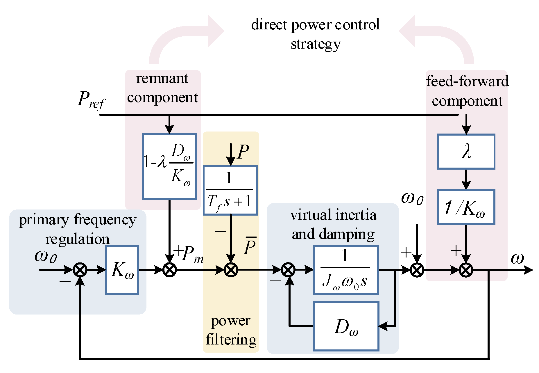
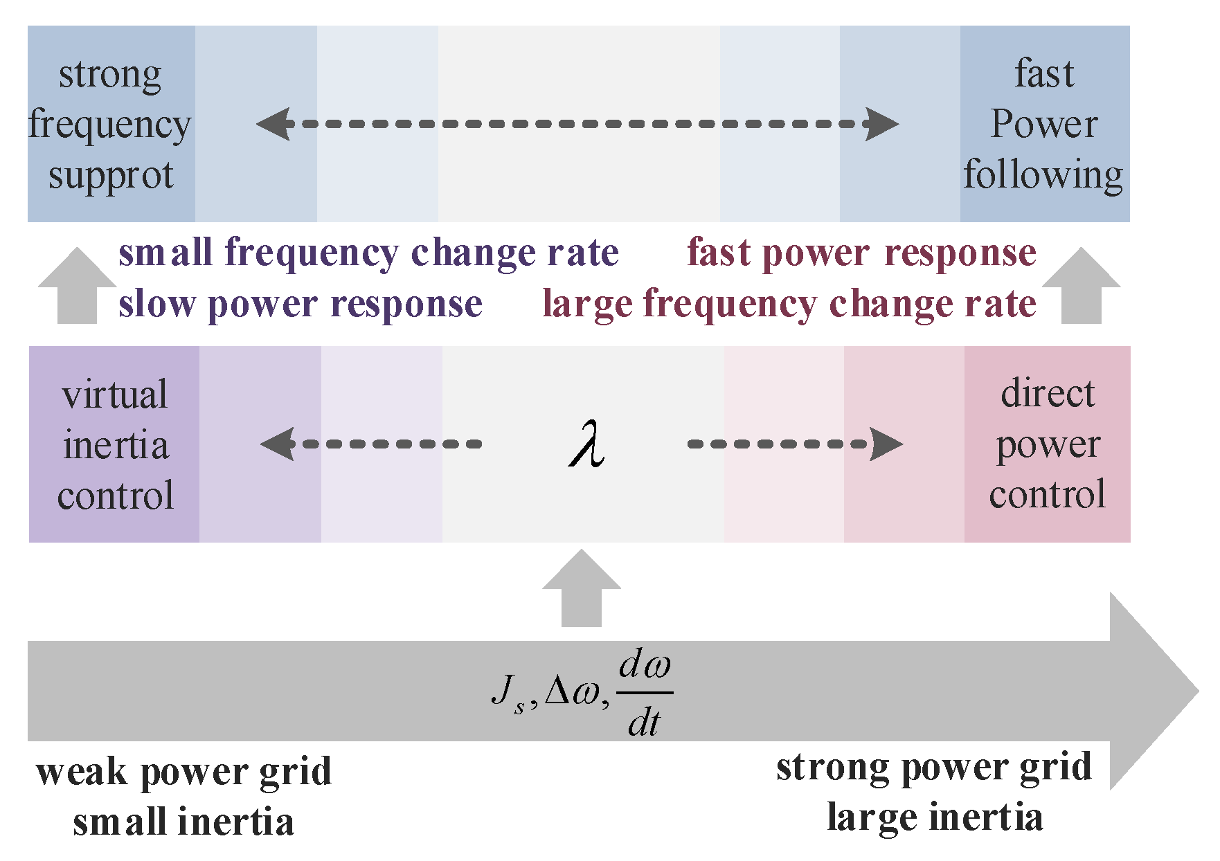
Based on the above reasons, a direct power control strategy based on VVSG is proposed. In the strategy, active power command Pref of the conventional VVSG outer active power control loop is divided into two parts: Pref*λ/Kω as the power command feed-forward component of direct power control, which is superposed on the frequency output of a conventional VVSG active power control loop to speed up the active power response. By changing the direct power participation factor λ, VVSG can realize smooth transition between large inertia characteristics and fast power following characteristic. Pref(1 − λDω/Kω), as the remnant component of direct power control, remains the same as Pref in a conventional VVSG active power control loop. The error between it and the output active power is sent to a virtual inertia link to gain an angular frequency output, thus ensuring that the steady-state output active power of VVSG always remains Pref when λ is adjusted to regulate dynamic characteristics of active power. Compared with the above voltage and current dual-mode control, VVSG with direct power control can perform large inertia characteristic in the weak grid and fast power following characteristic in the strong grid or under maximum power tracking requirement according to grid damping ratio and inertia demand just by adjusting λ, and without control structure switching and intermediate variable following. Moreover, the two characteristics can be smoothly transited. In addition, the frequency and voltage active support ability of the voltage source can be maintained under both characteristics.
This paper is organized as follows. In
Section 2, the output active power characteristics of a conventional VVSG are analyzed. Analysis results show that a conventional VVSG does not possess fast power following characteristics. In view of this problem, a direct power control strategy based on VVSG is proposed in
Section 3, the control structure is given, and the steady state and dynamic characteristics of VVSG output active power are analyzed. In
Section 4, simulation cases of a conventional VVSG and VVSG based on direct power control under various working conditions are designed, and the simulation results are analyzed.
Section 5 concludes the paper.
2. Output Active Power Characteristics of Conventional VVSG
Except P-ω and Q-V droop characteristics simulation of synchronous generator sets, the virtual inertia algorithm is carried out to simulate the true rotational inertia. Virtual inertia provides short-time power support in response to the rate of change of frequency, in order to prevents rapid frequency fluctuations. Primary frequency regulation provides continuous active support in response to frequency deviations, which prevents continuous frequency fluctuations of the system and eventually reaches a new steady state.
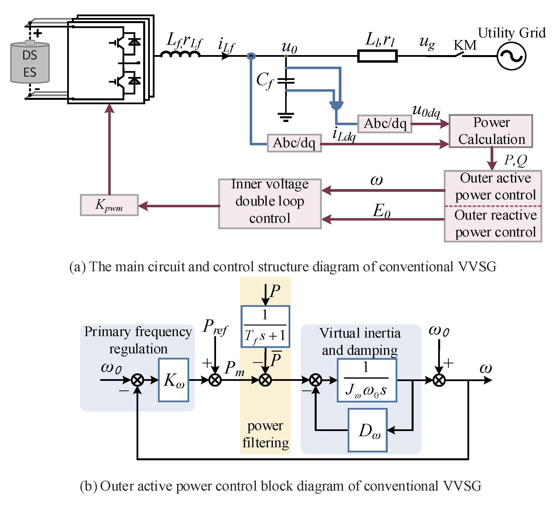
The conventional VVSG algorithm is described by Equation (1), the main circuit and control structure diagram is shown as
Figure 1a, and the closed-loop control block diagram of VVSG output active power is shown in
Figure 1b, which includes three sections: primary frequency regulation section, virtual inertia and damping section, and first-order low pass filtering of output active powers section. In formula (1),
Pref and
Qref are active and reactive power commands, respectively. When VVSG operates in grid-connected mode, it transmits power to the grid according to power command; when VVSG operates in multi-parallel mode,
Pref and
Qref are generally set to zero.
ω0 and
U0 are VVSG rated angular frequency and phase voltage amplitude, respectively;
kω and
KU are the primary frequency and voltage regulation coefficients, respectively. Generally, VVSG sets
kω and
KU values according to the relevant standards, which stipulate a maximum frequency deviation of 1% with rated active power and a maximum voltage amplitude deviation of 5% with rated reactive power [
24].
Tf is the first-order low-pass filter time constant. The instantaneous output active and reactive power of VVSG are low-pass filtered to obtain the average active and reactive power of
and
, respectively, thus to avoid power pulsation components generated by grid voltage and current harmonics or non-linear loads from affecting VVSG output voltage quality. In addition,
Jω is the virtual inertia and
Dω is the damping coefficient. For the VVSG algorithm adopted in this paper,
Dω acts in the same way as
Kω in mathematical expression; it works when VVSG frequency deviates no matter in steady-state or dynamic process.
It can be seen that VVSG converts an active power error into a frequency control signal through a virtual inertia link, thereby regulating the phase angle difference between VSG and the grid voltage, thus achieving indirect output active power control and active frequency support.
Considering the bandwidth of each control loop and as the bottom voltage and current closed loop of VVSG are neglected for analysis simplification, its active power closed loop transfer function for grid-connected mode can be obtained:
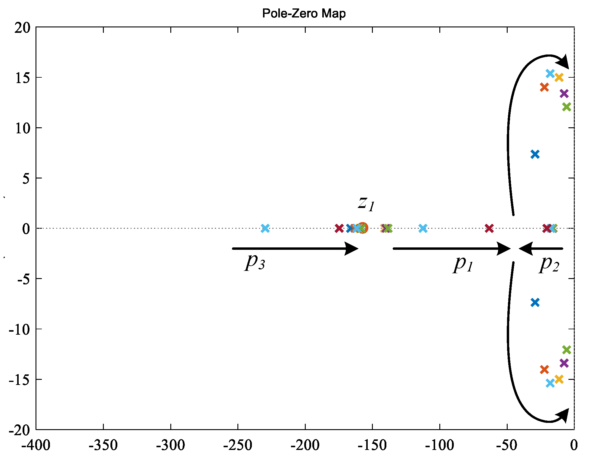
The active power characteristics of VVSG can be analyzed through transfer function
Gr(
s). The zero-pole diagram of
Gr(
s) with
Jω taking different values is shown in
Figure 2.
Gr(
s) is a third-order system with three poles and a zero, the position of zero is only determined by
Tf and does not vary with
Jω. With
Jω gradually increasing, the pole
p3 converges to zero point from the left side along the real axis, and eventually forms a pair of dipoles with the zero; the pole
p1 gradually moves to the right along the real axis from near the zero, and
p2 gradually moves to the left along the real axis from near the origin. As
Jω increases,
p1 and
p2 form a pair of conjugate complexes and move toward the imaginary axis, illustrating the damping ratio reduction. The system characteristic changes from overdamped to underdamped; as a result, the dynamic overshoot increases, and the regulation time lengthens. Therefore, while a large virtual inertia is set for VVSG to enhance frequency stability of weak grid, it also prevents active power error from being converted into frequency signal in time, hence slowing down active power response, making it difficult for VVSG to meet the requirement of power command fast-following.
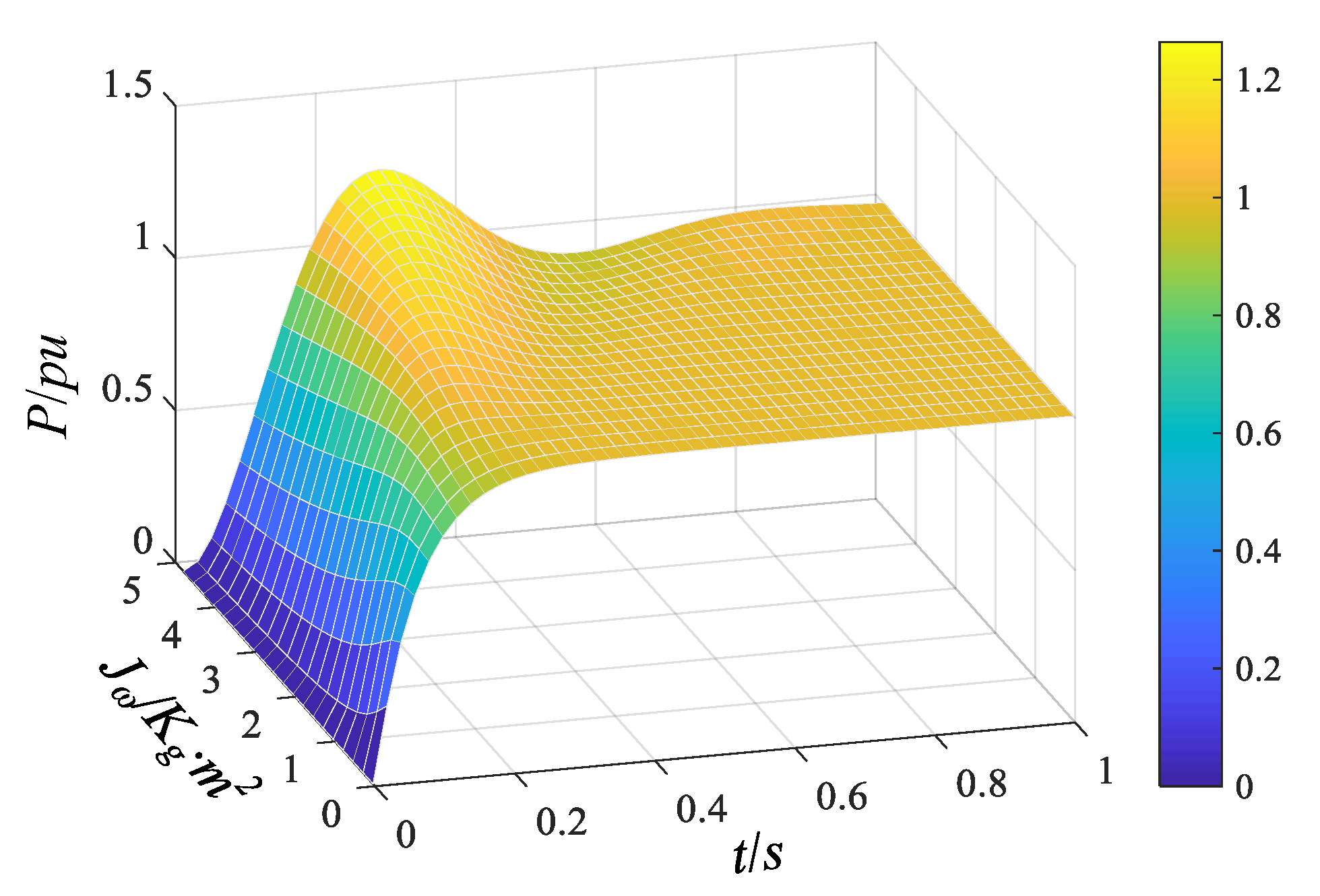
The step response of VVSG output active power with various
Jω are shown in
Figure 3. As
Jω varies from 0 to 1,
p3 is a non-dominant pole at a long distance,
p1 and
z1 form a pair of dipoles, and
p2 is a dominant pole near the origin with little change in position. Therefore, the active power step response curves basically coincide. With
Jω increasing continuously, the system changes to underdamped, the system initial response speed slows down, and both the overshoot and regulation times increase.
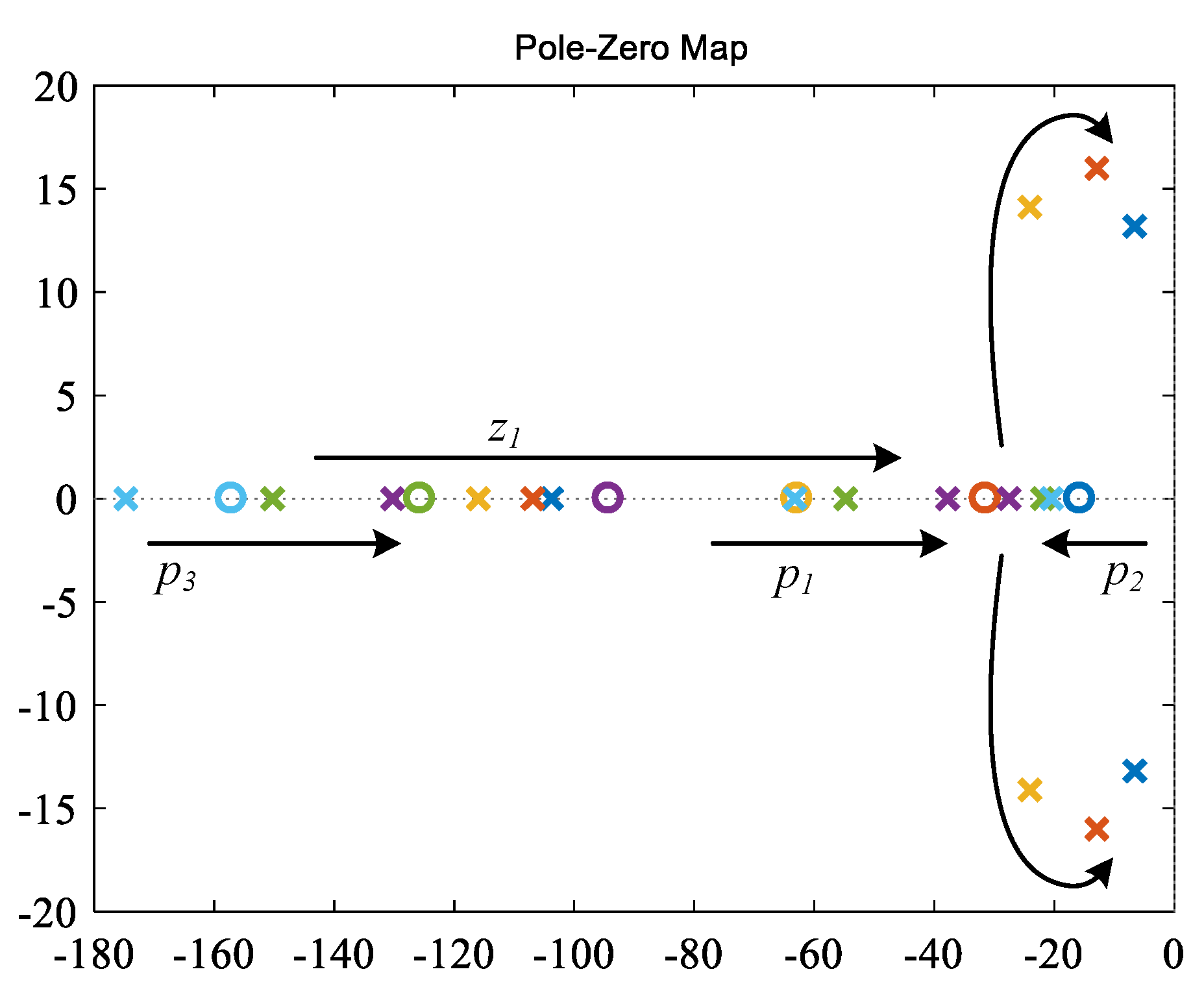
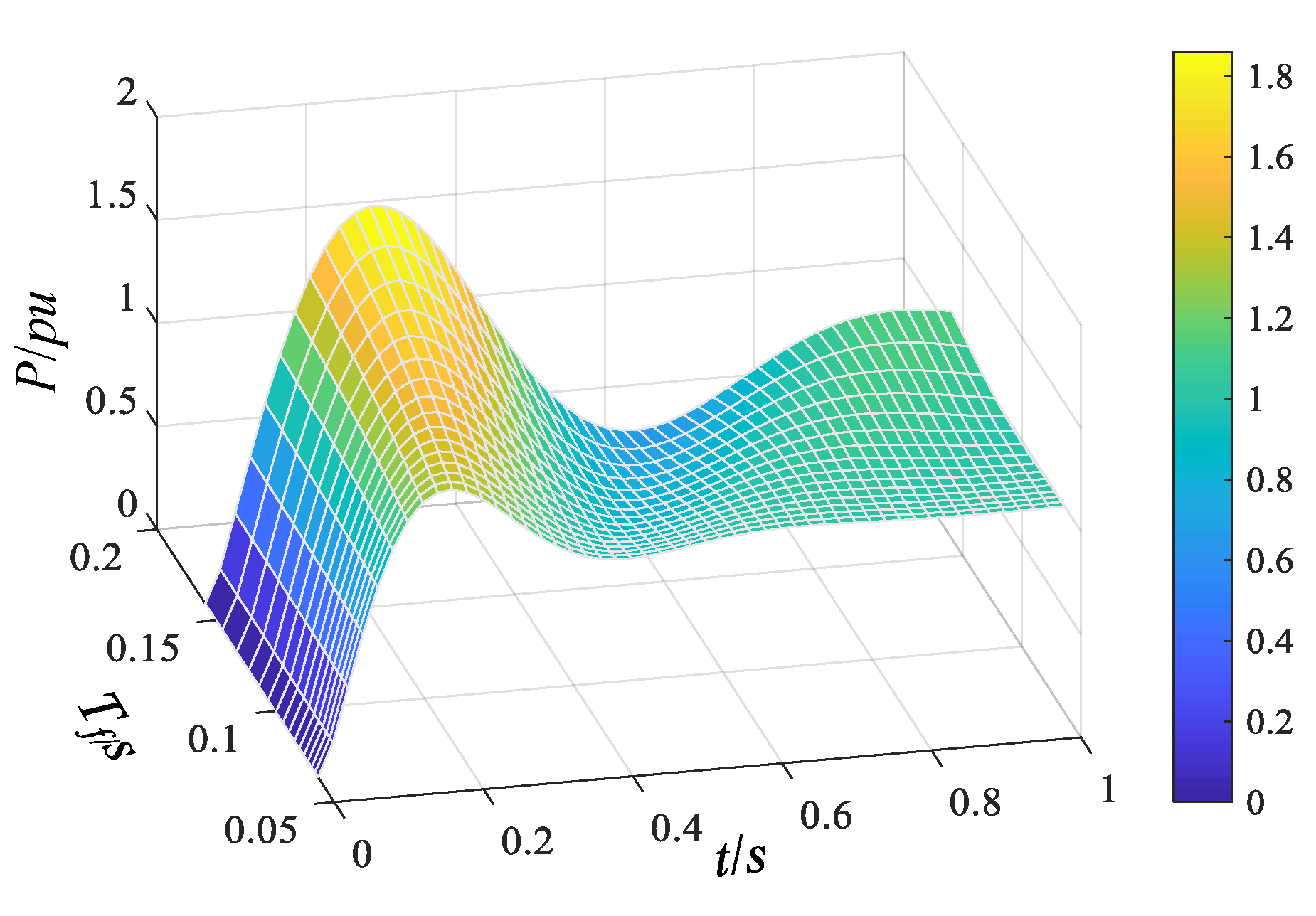
Even the grid is strong enough that a large virtual inertia support is not needed for VVSG operating in the grid-connected mode, but the first-order low-pass filter of output active power still performs the same time-delay effect. In order to filter out power pulsations induced by grid harmonics or nonlinear loads, the filter cutoff frequency is generally set to two to five times the fundamental frequency in tenths, hence the response speed of the output active power is reduced [
25,
26]. Setting
Jω = 1, and increasing
Tf gradually, the zero and poles trend of
Gr(
s) is shown in
Figure 4.
The pole
p1 moves to the right along the real axis,
p2 moves to the left along the real axis, and they gradually form a pair of conjugate complexes with their real part closing to the imaginary axis, indicating that the system changes from over-damped to underdamped, and the overshoot increases. The pole
p3 and zero
z1 gradually converge to the origin along the real axis. Since
p3 is a non-dominant pole, its influence on active power dynamic characteristic is small, while
z1 is closer to the imaginary axis, resulting in acceleration of active power response and reduction in the rise time. However, the regulation time still cannot meet the power fast following requirements of two to five cycles. The step response curves of VVSG output active power with various
Tf are shown in
Figure 5.
3. Direct Power Control Strategy Based on VVSG
In order to realize the power command fast following characteristics of a voltage-controlled new energy converter just as the conventional current-controlled new energy grid-connected converter, and to avoid control structure switching and intermediate variable following, a direct power control strategy based on VVSG is proposed, as shown in
Figure 6. In the figure, an active power command
Pref of a conventional VVSG outer active power control loop is divided into two parts: the power command feed-forward component
Pref*
λ/
Kω and the remnant component
Pref(1 −
λDω/
Kω).
λ is the participation factor of direct power control, which affects participation degree of the feed-forward component.
Pref*
λ/
Kω is superposed on the frequency output of a conventional VVSG active power control loop to speed up the active power response.
Pref(1 −
λDω/
Kω) remains the same as
Pref in a conventional VVSG active power control loop, ensuring that the steady-state output active power of VVSG always remains
Pref when
λ is adjusted to regulate the dynamic characteristics of active power.
According to
Figure 6, the active power closed-loop transfer function of VVSG in grid-connected mode can be obtained:
Compared with Equation (2), there is an extra differential term with respect to
λ in
Gr1(
s), which speeds up the active power response. As
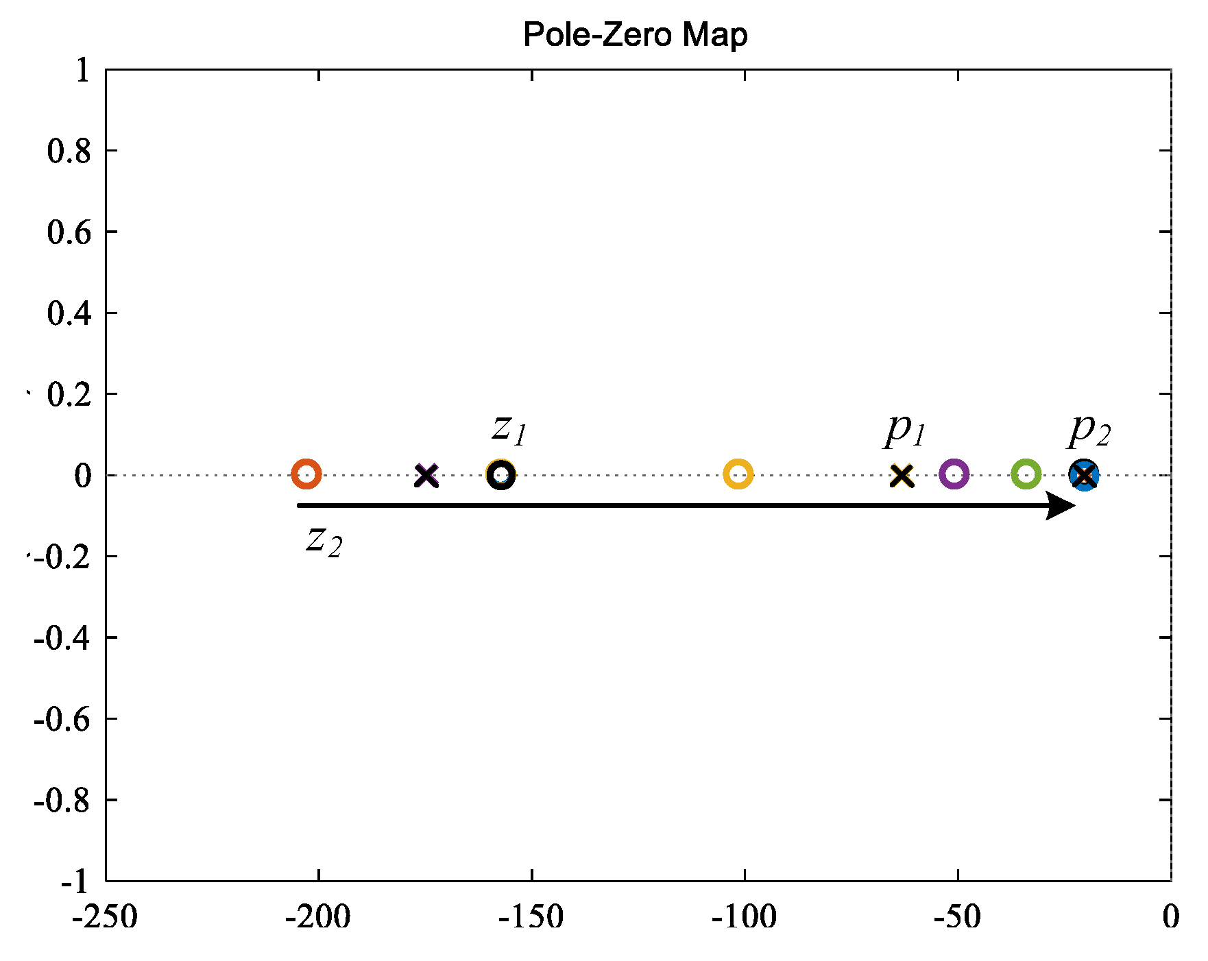
λ varies, the zero-pole diagram is shown in
Figure 7.
Gr1(
s) has three poles and two zeros; the zero
z1 and the poles
p1,
p2, and
p3 are the same as the zero and poles of
Gr(
s); and
z2 = –
Kω/(
λJωω0) is the new added zero point introduced by direct power control. As
λ gradually increases from 0 to 5,
z2 approaches the origin along the negative real axis and finally becomes the dominant zero point. Hence, the effect of the active power command differential term is gradually enhanced and the power response is accelerated.
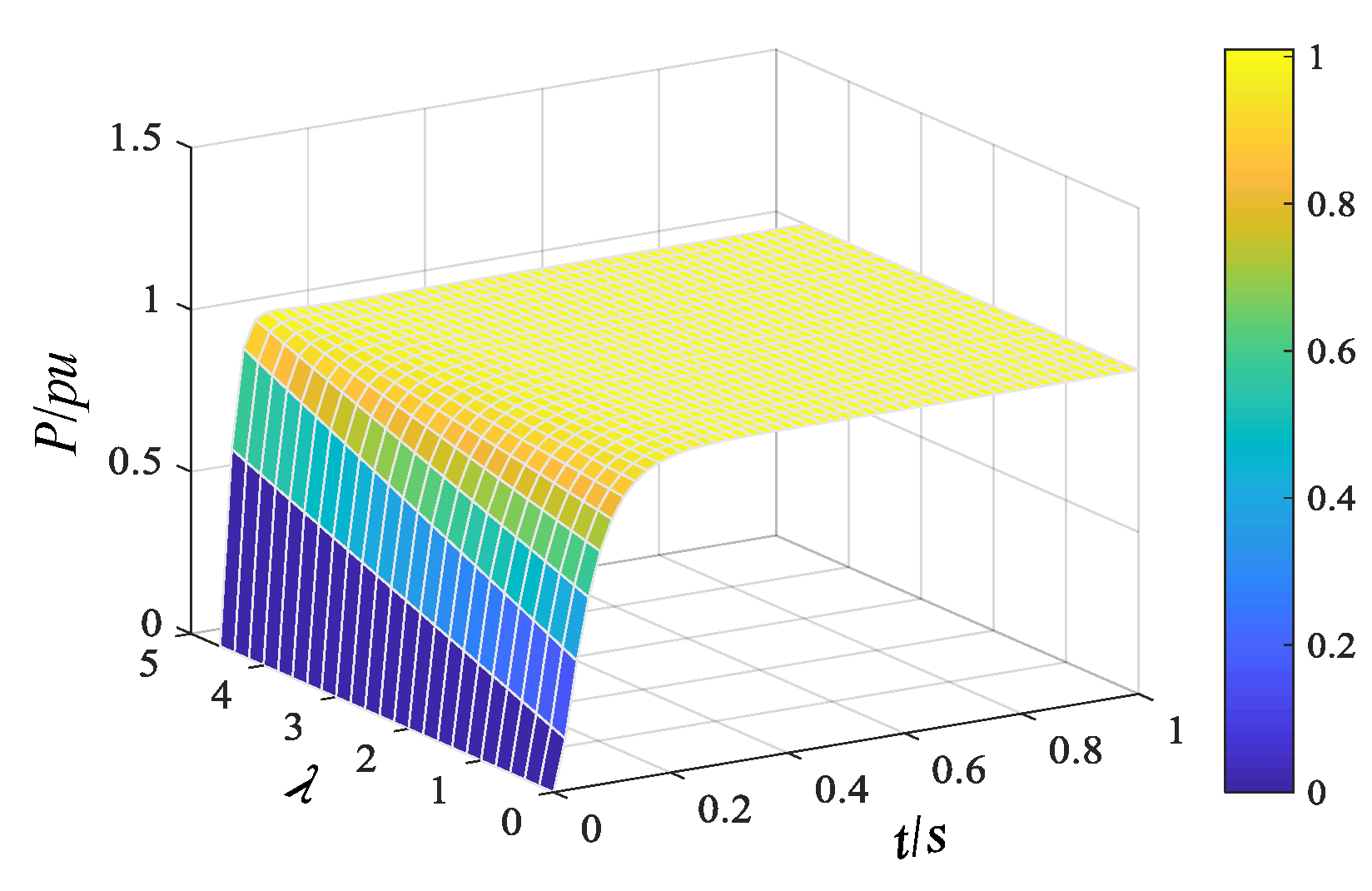
Figure 8 shows VVSG output active power step response curves with
λ varying from 0 to 5. As
λ increases, the response of output active power speeds up and the regulation time decreases. As
λ = 0, the feed-forward component of direct power control does not work, and the VVSG output active power regulation time is about 0.2 s. As
λ = 5, the regulation time is about 0.05 s, indicating that VVSG with direct power control possesses the fast power following characteristics similar to current-controlled converters.
In addition, by comparing Equations (2) and (3), we can see that Gf(s) without direct power control algorithm and Gf1(s) with direct power control algorithm are the same.
In summary, if the power grid is a weak grid with small inertia, and VVSG is adopted to enhance system stability, VVSG should perform slow power following and frequency variation characteristics with large virtual inertia. Setting
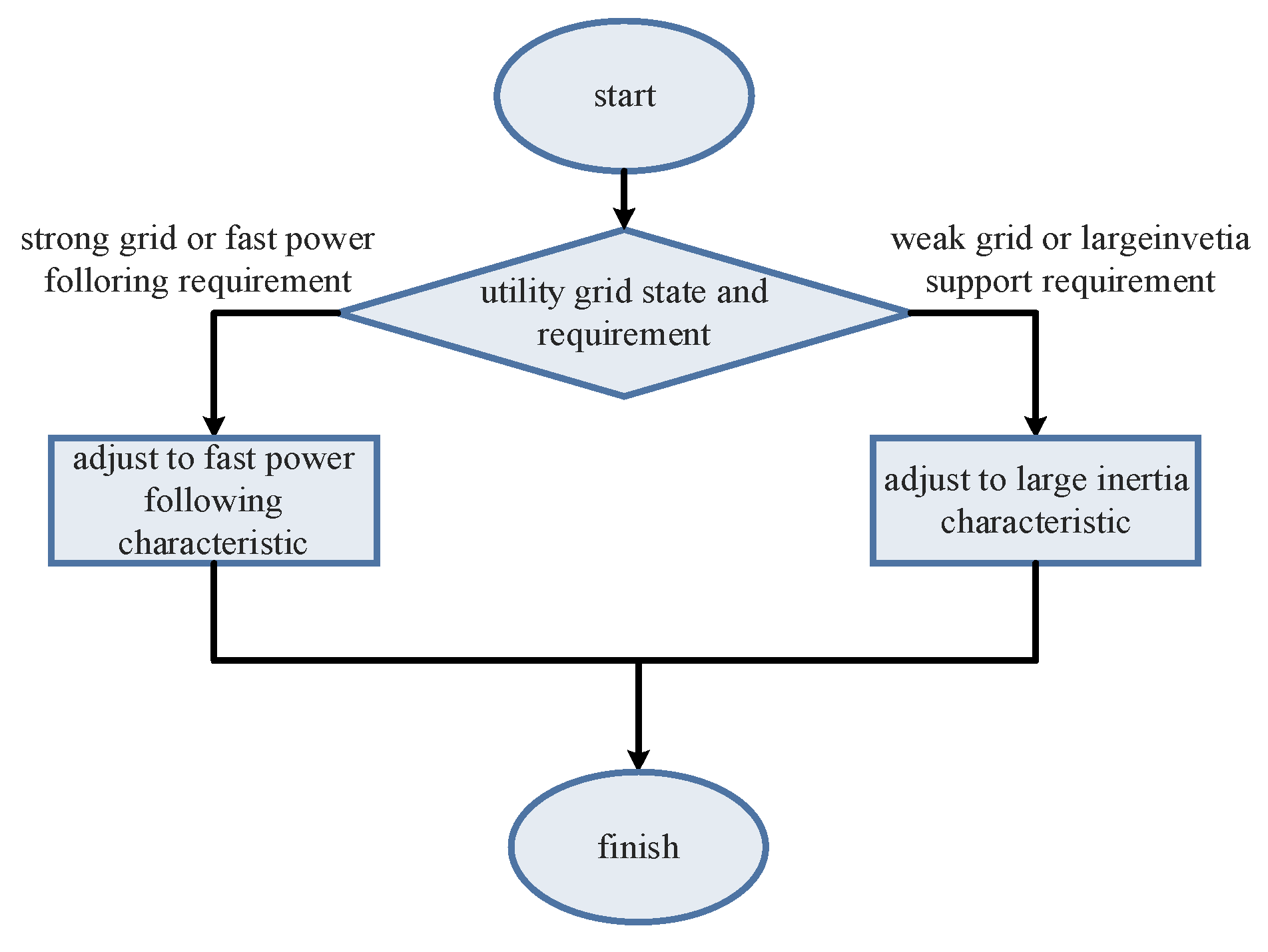
λ = 0, VVSG operates in a conventional voltage control mode, and its inertia and primary frequency regulation characteristics remain unchanged. If VVSG is connected to a strong grid with high inertia, or if it is required to quickly track active power command, it should mainly perform active power fast following characteristics with small virtual inertia and a large rate of change in frequency. By reasonable configuration of λ according to the state of the connected grid and the system inertia requirements, the smooth transition of VVSG between active power fast following characteristics and large virtual inertia characteristics without control mode switching and intermediate variable following can be achieved. Moreover, the voltage support capability is maintained under both characteristics, as shown in
Figure 9.
The characteristics transition of VVSG according to grid status and requirements can be briefly illustrated with a flow chart shown in
Figure 10.
4. Simulation Analysis
In this paper, a 100-kW VVSG grid-connected simulation platform is established in MATLAB/Simulink environment to verify the output active power and frequency steady-state and dynamic characteristics of the conventional controlled VVSG as well as VVSG with direct power control. The main parameters of the simulation model are shown in
Table 1.
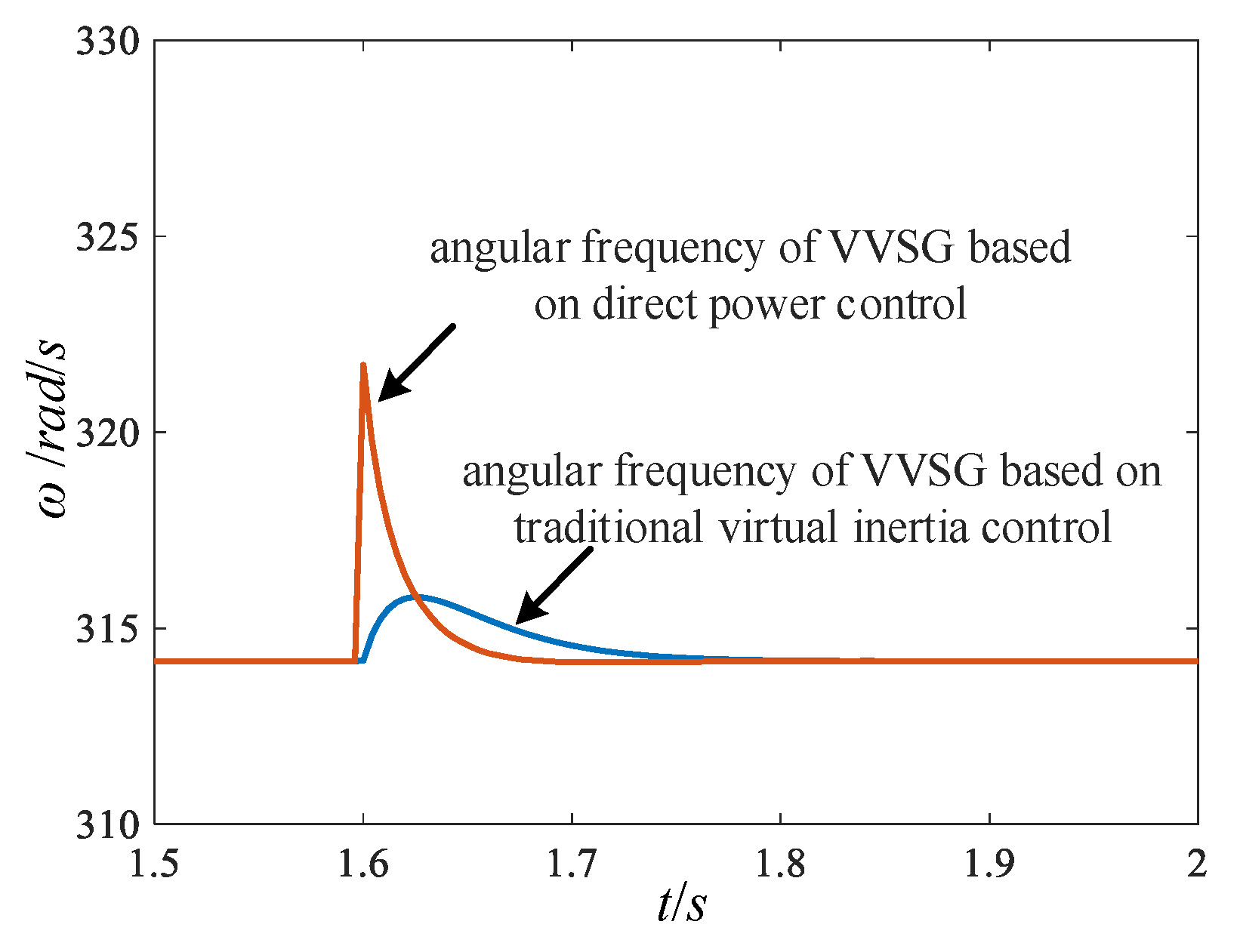
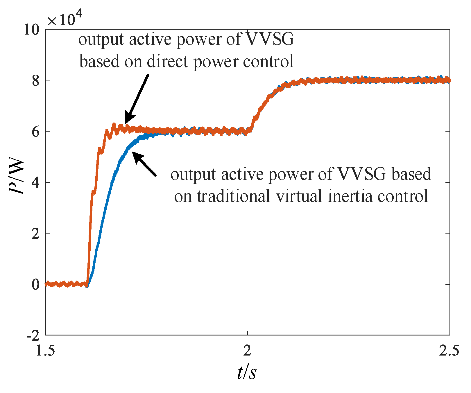
Case 1: The conventional VVSG and the VVSG with the direct power control algorithm are connected to a strong utility grid at 1.5 s separately. The grid inertia is large, and its frequency does not fluctuate. At 1.6 s, the active power command increases from 0 kW to 60 kW. The waveforms of VVSG output active power are shown in
Figure 11, and the angular frequency waveforms are shown in
Figure 12. Due to the large virtual inertia, VVSG output active power regulation time is as long as 0.2 s before it reaches steady state. While active power response of VVSG with direct power control algorithm is so fast that its active power regulation time can be within 0.06 s. In
Figure 12, since the active power command feedforward component of the direct power control algorithm is directly superimposed on VVSG angular frequency, the angular frequency surges when active command increases, while the large inertia of the grid ensures that the system frequency is not affected by VVSG frequency fluctuation.
Case 2: The conventional VVSG and the VVSG with a direct power control algorithm are connected to a utility grid at 1.5 s separately. At 1.6 s, the active power command increases from 0 kW to 60 kW, and from 2.0 s the grid frequency deviates 0.2%, the waveforms of VVSG output active power are shown in
Figure 13. As the grid frequency decreases, the steady-state output active power increases by 20kW. In addition, the active power response of conventional VVSG and VVSG with a direct power control algorithm to grid frequency deviation are the same, indicating that direct power control only affects VVSG output active power characteristics when the active power command changes, so that it will not affect its active frequency support capability.
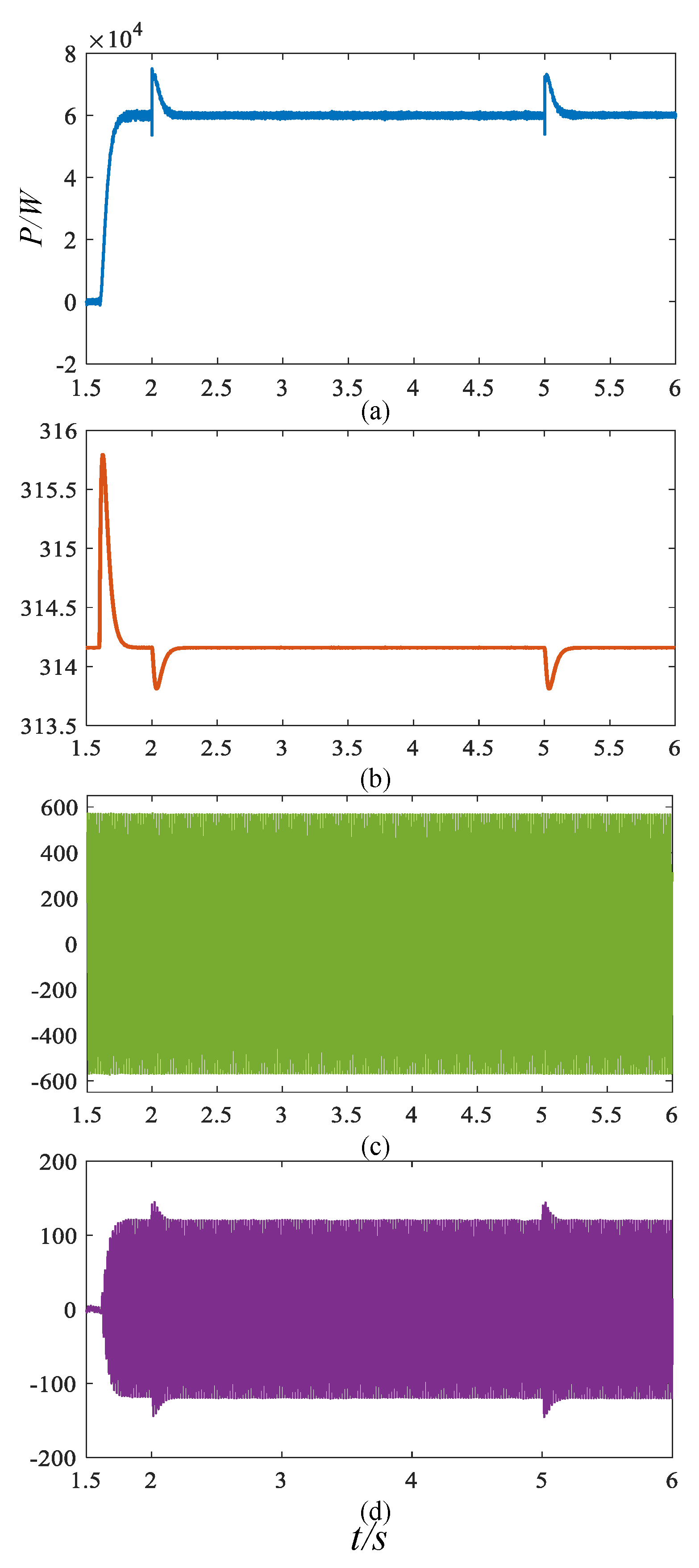
Case 3: The VVSG with direct power control algorithm is connected to a strong utility grid at 1.5 s, and the active power command increases from 0 kW to 60 kW at 1.6 s. At 2 s, due to the grid operation state changes, it becomes a weak grid and the system inertia is reduced. VVSG perform larger virtual inertia characteristics to support system frequency. At 5 s, the active power command increases from 60 kW to 90 kW.
Figure 14 shows the waveforms of VVSG output active power, angular frequency, line voltage, and phase current during the characteristics transition and command step. In order to avoid active power impact, a first-order linear function of
λ =
f(
t) is set in the simulation and
λ reduces to zero at 4 s. In the figure, it can be seen that VVSG output active power and frequency basically do not fluctuate. At 5 s, as VVSG performs large virtual inertia characteristics, and its output active power characteristics are the same as in case 1.
Case 4: The VVSG with direct power control algorithm is connected to a strong utility grid at 1.5 s, and the active power command increases from 0 kW to 60 kW at 1.6 s. At 2 s, a 12-kW load is connected to PCC point. At 2.5 s, the grid becomes a weak grid, and VVSG transits to large virtual inertia characteristics to support system frequency. At 5 s, a 12-kW load is connected to the PCC point. The waveforms of VVSG output active power, output frequency, line voltage, and phase current during the characteristic transition and active command step are shown in
Figure 15. No matter whether the direct power control component works or not, when the system load increases, VSG acts as a voltage source with active support capability, and suppresses system frequency fluctuation by reducing its own frequency change rate and supplying short-time active power.


