Highlights
What are the main findings?
- Hybrid steel and polypropylene fibers significantly enhance the freeze-thaw resistance of high-strength concrete; the optimal mix (Group A3: 35 kg/m3 steel fiber + 1.5 kg/m3 of 18 mm PPF) maintained a relative dynamic modulus of elasticity of 94.5% and limited mass loss to just 1.42% after 125 cycles.
- Numerical simulations using a concrete damage plasticity model confirmed that the hybrid fiber system effectively mitigates thermal stress and damage evolution, limiting compressive strength degradation to only 6.7% under coupled freeze-thaw and axial loading.
What is the implication of the main finding?
- The validated synergistic mechanism of hybrid fibers provides a robust, data-supported reference for designing high-durability concrete, offering a 41% improvement in frost resistance compared to traditional non-fibrous concrete.
- These findings support the application of high-strength concrete in cold-region tunnel infrastructure, ensuring long-term structural integrity and reducing maintenance costs by quantitatively predicting damage evolution.
Abstract
High-strength concrete (HSC) is vital for large-scale tunnel infrastructure; however, its durability is often compromised by rigorous freeze–thaw cycles in cold-region environments. This study investigates the synergistic effects of incorporating hybrid steel fiber (SF) and polypropylene fiber (PPF) to enhance the frost resistance of HSC. Experimental testing involved 125 freeze–thaw cycles across various fiber dosages and lengths, monitoring mass loss and the relative dynamic modulus of elasticity. Additionally, a concrete damage plasticity (CDP) model was utilized in numerical simulations to analyze thermal stress distribution and damage evolution under coupled freeze–thaw and axial loading. Results indicate that the hybrid fiber integration significantly improved durability, with Group A3 (35 kg/m3 SF and 1.5 kg/m3 of 18 mm PPF) achieving the highest performance. After 125 cycles, Group A3 maintained a relative dynamic modulus of 94.5% and restricted mass loss to 1.42%, a 41% improvement over the fiber-free control. Numerical simulations corroborated these findings, demonstrating that the dual-fiber system preserves load-bearing capacity, limiting compressive strength degradation to just 6.7%. These findings quantitatively validate the synergistic mechanisms of hybrid fibers, providing a robust reference for designing high-durability concrete in cold-climate engineering applications.
1. Introduction
The scale of infrastructure construction is continuously expanding. The external environment faced by engineering projects is also becoming increasingly complex. Performance standards for concrete materials have changed significantly. High strength is no longer the sole consideration. Long-term durability and material toughness have also become key priorities [1]. These properties are particularly crucial for the construction of undersea tunnels. In addition to relying on a high-strength framework to withstand the huge hydrostatic pressure of the deep sea, submarine tunnels also have demanding requirements for the density and impermeability of materials. What is more troublesome is that the tunnel entrance and transition section are directly exposed to the outside. In cold regions, these locations will repeatedly experience the processes of freezing and thawing.
Moisture repeatedly undergoes the physical phase change of “freezing expansion and melting contraction” in the micropores of concrete, which will generate severe periodic internal stress. This stress is like countless tiny wedges, forcibly opening cracks in the matrix, eventually causing the structure to disintegrate from the inside out. Gradually, many tiny cracks will grow inside. As the cracks become more numerous and larger, the mechanical properties of concrete will drop significantly, eventually leading to the shortened lifespan of the entire project [2,3]. To ensure the safe operation of undersea tunnels for decades, it is essential to study the performance changes of high-strength concrete (HSC) in cold environments.
Adding fibers to concrete is a common solution. Fibers can “hold” concrete that is about to crack, making the material more resilient and less prone to breakage [4]. Currently, steel fibers (SF) and polypropylene fibers (PPF) are commonly used on construction sites; each has its own strengths [5,6]. Studies have found that adding SF to recycled concrete significantly increases the shear strength of beams compared to ordinary concrete [7]. Smarzewski [8] provided some research data. SF has a very significant effect on ultra high-performance concrete. Energy absorption capacity can typically be increased by about 220 to 650 times. Fracture energy can be increased by 175 to 520 times. Concrete without added fibers performs poorly in these indicators. Ahmad et al. [9] focused on the performance of PPF and showed that this material can reduce the water absorption rate of concrete. The occurrence of drying shrinkage cracks was effectively controlled. The overall durability of concrete was improved. Researchers observed the samples using scanning electron microscopy. The fibers made the microstructure inside the concrete more compact. The tensile strength and long-term durability of the material were enhanced. Gong et al. [10] pointed out the specific contributions of PPF. The fibers can inhibit the formation of pores inside concrete. The process of pores expanding outward was slowed down. The salt-freeze resistance of concrete was significantly improved. The increased fiber content made the structure more stable in salt-freeze cycles. The freeze resistance performance was excellent.
Single fibers have their own limitations in improving performance. SF excels at improving strength and ductility. Its effect on improving concrete’s impermeability is not significant. PPF focuses on enhancing durability. This fiber is beneficial for tensile properties and ductility. Its effect on improving compressive strength is relatively limited. Therefore, researchers have considered combining these two fibers to leverage their complementary advantages [11,12]. Studies have shown that SF can macroscopically hold large cracks together, while PPF can microscopically fill small pores. Through cross-scale synergy between SF and PPF, the splitting tensile strength of the material showed an increase of 10% to 35% in experiments [13]. Furthermore, the combined use improves workability during construction, makes the material denser, and slows down the aging process [14,15]. In salt-freezing environments, the performance improvement of concrete mixed with these two fibers was very significant [16].
However, much of the current research remains at the stage of observing experimental results. The fundamental reason why concrete deteriorates is the continuous change in internal temperature and water pressure [17,18,19]. It is difficult to see clearly how concrete cracks inside, little by little, just by looking at it with the naked eye or by simple experiments. This is where numerical simulation comes in handy, as it can recreate the entire damage process [20,21]. This study focuses on HSC blended with SF and PPF. The durability of the material under freezing conditions is a key aspect. Different fiber combinations and dosages were used in the experiment. The performance degradation of the concrete after multiple freeze–thaw cycles was compared. The temperature change process under freeze–thaw conditions was simulated using ABAQUS CAE 2022 software. The distribution of internal thermal stress was demonstrated in the model. The study explains, in principle, how the mixed fibers maintain the strength of concrete and extend its lifespan.
2. Materials and Methods
2.1. Test Specimen Material and Mix Proportion
To ensure the matrix properties of HSC, this study selected P·O 52.5R ordinary Portland cement as the cementitious material. For aggregate selection, 5–20 mm continuously graded crushed stone was used as the coarse aggregate, as this type of crushed stone has a low crushing index. Medium sand with a fineness modulus of 2.6 was used as the fine aggregate, characterized by hard texture and low clay content. To enhance the workability and later strength of concrete, polycarboxylic acid-based high-efficiency water-reducing agents were incorporated, and cement was partially replaced with Grade I fly ash and S95-grade powdered minerals. The fibers employ a hybrid blend of SF and PPF, with SF fibers measuring approximately 35 mm in length and PPF fibers ranging from 9 to 18 mm. The morphology of the hybrid fibers is presented in Figure 1, with their detailed mechanical properties listed in Table 1 and Table 2.
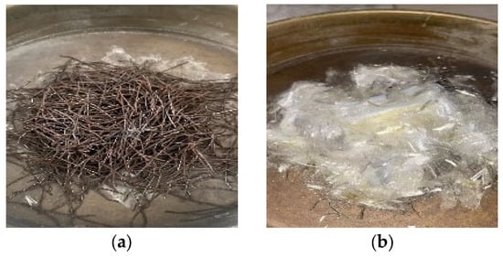
Figure 1.
Fiber appearance. (a) SF; and (b) PPF.

Table 1.
Properties of SF.
Table 2.
Properties of PPF.
The experimental design referenced reference [22] and the engineering requirements of the Qingdao Jiaozhou Bay Second Subsea Tunnel. The concrete strength was set at C60 grade. The water–cement ratio was below 0.33, the amount of cementitious material was between 400 and 500 kg/m3, and the slump was controlled within 70 mm. The binder materials included cement, fly ash, and ground granulated blast-furnace slag (GGBS), with the latter being S95-grade powdered minerals. The experiment focused on testing the effects of fiber type, dosage, and length using the controlled variable method. Among the many mix proportions, four groups, A1, A2, A3, and A4, were selected for in-depth analysis. At the same time, group A0 was set as a control without fibers. The specific parameters of each group are recorded in Table 3.
Table 3.
Mix design of concrete specimens.
2.2. Specimen Preparation and Curing
To ensure that the fibers were distributed more evenly in the concrete and to avoid clumping, all materials were thoroughly mixed using a forced mixer. For the frost resistance test, a 100 mm × 100 mm × 400 mm prism mold was used for casting. During the manufacturing process, air bubbles were removed by a repeated vibration on a vibrating table to make the interior more compact. After smoothing the surface, the specimen was covered with a plastic film to prevent moisture from evaporating too quickly and causing cracks. Subsequently, these specimens were sent to a standard curing room and left to stand for 28 days at 20 ± 2 °C and above 95% humidity. Before the formal start of the freeze–thaw test, the specimens also needed to be air-dried at room temperature for 2 days. After these preparations were completed, the core test stage followed.
2.3. Test Method
2.3.1. Freeze–Thaw Cycling Procedure
The frost resistance test used the standard rapid freezing test method. The operation procedure followed the national standard GB/T 50082-2024 [23]. The specimens needed to be soaked in water for 24 h before the formal test. The freeze–thaw chamber (Figure 2) was the main experimental environment. The internal temperature of the chamber fluctuated between −18 °C and 20 ± 2 °C. A complete cycle took 4 h. The entire experimental process was set for 125 cycles. Specimens were removed and measured every 25 cycles. The experiment was terminated if the relative dynamic modulus of elasticity dropped to 60%, mass loss reached 5%, or the 125-cycle limit was reached.
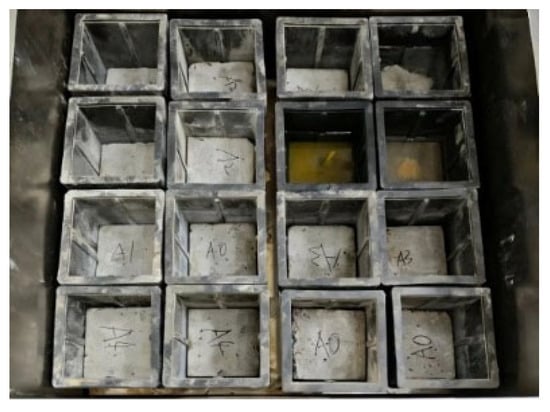
Figure 2.
Specimens in the freeze–thaw chamber.
2.3.2. Measurement of Mass Loss and Relative Dynamic Modulus
The mass loss rate (m) and the relative dynamic modulus of elasticity (Er) were the core indicators. To ensure data reliability, each specimen was wiped dry and weighed to calculate mass loss. The relative dynamic modulus of elasticity was determined using a non-destructive dynamic modulus tester by measuring the transverse fundamental frequency (f). For each specimen, three measurements were performed; the average value was used. Er was calculated as follows:
where is the initial transverse fundamental frequency before freeze–thaw cycles, and is the frequency after n cycles.
3. Test Results and Analysis
3.1. Freeze Resistance Test Results and Analysis
Figure 3 records the performance data of concrete under different cycles. To ensure statistical reliability, each data point represents the average of three replicate specimens (n = 3); the variability is indicated by error bars. These data include specific performances from 25 to 125 cycles. The type of fiber affects the final freeze–thaw resistance. The amount and length of fiber added are also important variables. The baseline group A0 did not contain any fibers. Notably, the mass loss rates for all fiber-reinforced groups (A1, A2, A3, and A4) were negative after 25 cycles, indicating a slight increase in specimen weight. This phenomenon is not coincidental; it is primarily attributed to the water-saturated state of the specimens. During the initial stage, external water gradually penetrates the initial micropores and the interface transition zones between the fibers and the cement matrix. Furthermore, the presence of unhydrated cementitious particles in the C60 high-strength concrete facilitates continued hydration when immersed in water, leading to a mass gain that initially offsets the minor surface scaling [19]. As the cycles progressed beyond 50 cycles, the cumulative frost damage on the concrete surface became dominant, resulting in a progressive increase in mass loss. After 125 cycles, the relative dynamic modulus of elasticity of this group became 86.5%. The weight loss rate reached 2.4%. Obvious peeling and damage appeared on the surface of the specimens. Specimens with added SF and PPF performed better. These fibers blocked the growth path of microcracks. SF acted like a bridge connecting the internal materials. This effect improved the stiffness and stability of the concrete. PPF enhanced the toughness of the material. The stress concentration caused by temperature was alleviated. The freeze–thaw resistance increased with the increase in fiber content. This strengthening trend became stable in the later stages. The optimal fiber addition range was confirmed in the experiment. The mixed use of the two fibers produced a good synergistic effect.
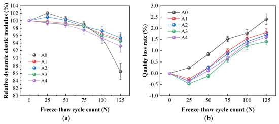
Figure 3.
Test data of the specimen under different freeze–thaw cycles (n = 3 per group): (a) relative dynamic elastic modulus; and (b) quality loss rate.
Among all the experimental groups, group A3 exhibited the most balanced and superior overall frost resistance. Although group A2 showed a slightly higher relative dynamic modulus of elasticity (95.4%), group A3 achieved the minimum mass loss rate after 125 cycles. Considering the dual requirements of maintaining structural integrity (minimum mass loss) and stiffness (high dynamic modulus), group A3 was identified as the optimal mix proportion. This comprehensive performance makes group A3 the most representative case for further investigation in the numerical simulation section, as it provides the most effective protection against surface scaling while maintaining a high level of internal compactness. The hybrid fibers significantly enhanced the lifespan of concrete under freezing conditions.
3.2. Parameter Correlation Analysis
The study used experimental data from groups A0 to A4 (Table 4). In this analysis, the investigated variables included the dosage of SF, the dosage of PPF, and the PPF length (denoted as L). The core durability indicators evaluated were the mass loss rate (denoted as m) and the relative dynamic modulus of elasticity (denoted as Er). Pearson correlation coefficients were used to calculate the relationship between these indicators. The correlation coefficient heatmap visually illustrates the relationship between the variables.
Table 4.
Key performance indicator dataset.
Figure 4 presents the correlation coefficient heatmap, where the color intensity and numerical values represent the strength of the linear relationship between variables. The graphic symbols in the heatmap indicate the direction of correlation: a positive value (approaching 1) denotes a strong positive correlation, while a negative value (approaching −1) signifies a strong inverse relationship. As shown in Figure 4, the amount of PPF is closely inversely related to the mass loss rate (m), with a correlation coefficient of −0.980, suggesting that PPF is the most dominant factor in mitigating surface scaling. The amount of SF used significantly affects the relative dynamic modulus of elasticity (Er). This material is very helpful in maintaining the stiffness of concrete.
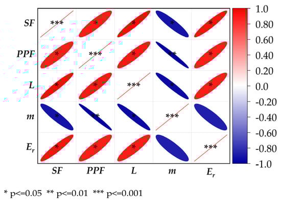
Figure 4.
Pearson correlation coefficient heatmap.
4. Simulation Verification
To investigate the internal damage process of hybrid fiber-reinforced HSC under freeze–thaw cycles, a cubic specimen model was established using the finite element software ABAQUS. A concrete damage-plasticity model was incorporated to numerically simulate the freeze–thaw cycling process of the hybrid-fiber concrete. The temperature field, thermal stress field, and compressive force of the material during the cycles of freeze–thaw were analyzed. Since the freeze–thaw test indicated that Group A3 exhibited the best durability performance, this specific condition was selected for numerical simulation.
It should be noted that the current numerical model primarily focuses on the thermal stress induced by the temperature gradient during freeze–thaw cycles. While the coupled effects of ice expansion and hydraulic pore pressure are significant factors in concrete degradation, the meso-scale model employed in this study treats the concrete matrix as a simplified multi-phase medium, where frost damage is indirectly captured through the evolution of thermally induced micro-strains and plastic damage. This simplification is adopted to maintain computational efficiency while still allowing for the investigation of the bridging effects of hybrid fibers on macro-crack propagation. The omission of explicit pore pressure modeling is an acknowledged limitation that will be addressed in future multi-physics investigations.
4.1. Model Establishment
The geometric model consists of a C60 HSC cube with a side width of 100 mm. While the experiments utilized 100 mm × 100 mm × 400 mm prisms, a 100 mm cubic representative volume element was adopted for the meso-scale simulation. This dimension is sufficient to characterize the random distribution of hybrid fibers and capture their synergistic bridging effects on damage evolution. This approach ensures the computational feasibility of modeling thousands of individual fibers while maintaining statistical representativeness, conforming to established practices in the meso-mechanical analysis of concrete materials. The random distribution of fibers was generated using a Python 3.8 script. Concrete cubes were modeled using eight-node thermally coupled hexahedral elements (C3D8RT), with a mesh size of 3 mm, set according to the model scale. The PPF and SF used T3D2 elements. This is a two-node balanced truss element. The fiber mesh density was set to 2 mm. Figure 5 shows the mesh details of plain concrete and fibers.
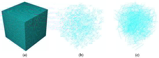
Figure 5.
Grid partitioning diagram: (a) plain concrete; (b) PPF; and (c) SF.
4.2. Constitutive Model
4.2.1. Concrete Constitutive Model
The simulation process used the concrete damage plasticity model (CDP) [24,25] built into ABAQUS. It can show the damage evolution of concrete under compression and tension. Damage accumulation and crack growth processes during freeze–thaw cycles can be reflected in the calculation.
(1) Stress–Strain Relationship and Damage Factor
The model reflects the degradation of material stiffness through the damage factor. The relationship between effective stress () and true stress () is given by the formula:
where represents the initial elastic modulus, represents the total strain, and represents the plastic strain. The damage factor ranges from 0 to 1.
(2) Plastic Yield Criterion
The model follows the isotropic hardening criterion. The specific expression for the yield function is:
where refers to the effective hydrostatic pressure, refers to the effective Mises equivalent stress, refers a dimensionless measure of the biaxial compressive force to the uniaxial compressive force ratio in concrete, refers the strengthening function associated with equivalent plastic strain, refers the maximum principal effective stress, is a parameter related to the shape of the yield surface, and is the effective cohesive stress, which serves as a strengthening function related to the equivalent plastic strain.
(3) Flow Laws and Stiffness Degradation
The model uses the non-associated flow law. The plastic potential function is in hyperbolic form:
where represents the uniaxial tensile strength, represents the dilation angle controlling volumetric expansion due to plastic flow, and is a small value of eccentricity.
4.2.2. Fiber Constitutive Model
Both types of fibers were simulated using an ideal elastoplastic model. The fibers follow a linear elastic law in the low-stress stage:
where represents fiber stress, represents fiber strain, and represents the elastic modulus.
The stress remains constant after reaching the yield limit. This setting simulates the energy absorption behavior of the fiber at cracks.
The interaction between the fibers and the concrete matrix was defined using the embedded region constraint. While this approach assumes a perfect bond and simplifies the slip or pull-out behavior, it is a standard and effective methodology for meso-scale models containing thousands of individual fibers. As demonstrated in recent research by Lian et al. [26], this modeling strategy—coupled with Python-based random fiber generation—ensures numerical convergence and computational feasibility while accurately capturing the global mechanical response and damage evolution of fiber-reinforced composites.
4.3. Temperature Field Simulation
Table 5 and Table 6 list the thermal parameters of the concrete and fibers. The transient heat transfer type was selected for the analysis step. The thermal conductivity of concrete used in the simulation was set at 3 W/m·K. In the numerical simulation process, the steel fibers and the concrete matrix are treated as a unified whole rather than being modeled individually. Although this value is higher than that of plain concrete (typically 1.0–1.5 W/m·K), it is justified by the inclusion of high-dosage SF, which possess a much higher thermal conductivity (approximately 17–18 W/m·K). The presence of SF creates efficient thermal conductive paths within the composite material, thereby significantly enhancing the overall equivalent thermal conductivity.
Table 5.
Material parameters for concrete in temperature field simulation.
Table 6.
Material parameters for fiber in temperature field simulation.
The simulation duration varies depending on the number of cycles. The analysis step time lengths for the 25, 50, 75, 100, and 125 freeze–thaw cycles were set to 3.60 × 10⁵, 7.20 × 10⁵, 1.08 × 10⁶, 1.44 × 10⁶, and 1.80 × 10⁶ s, respectively. Each freeze–thaw cycle was divided into two periods: cooling and heating. The ambient temperature fluctuated between −20 °C and +20 °C. A piecewise amplitude function controlled the temperature change. The cooling process lasted 2.75 h, and the heating phase lasted 1.25 h.
Transient heat conduction calculations provided the temperature evolution data of the specimen. Figure 6 shows the temperature distribution cloud map at different stages. The temperature distribution exhibits a ring-shaped structure from the outside in. The outer surface responds quickly to temperature changes, while the internal temperature changes show a significant lag. Taking 50 cycles as an example, during heating, the outer surface is approximately 19.8 °C, while the center is only 14.7 °C. During cooling, the outer surface reaches −19.2 °C, while the center is only −12.7 °C. This lag effect indicates that the heat conduction rate is finite. A temperature gradient always exists inside the concrete during the freeze–thaw process.
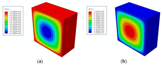
Figure 6.
Temperature change cloud diagram during freeze–thaw cycle: (a) heating; and (b) cooling.
4.4. Thermal Stress Field Simulation
In the thermal stress field simulations, the geometric model and mesh configuration were identical to those used for temperature field simulations. The analysis step type was set to static, general. All other settings remained consistent with those for temperature field simulations. When simulating thermal stress fields, a plastic damage model is employed for concrete. In the parameter configuration of this model, in addition to conventional mechanical performance indicators, the thermal expansion coefficient was incorporated to characterize the volumetric deformation behavior of concrete under varying temperature conditions. The key parameters of the CDP model adopted for the mechanical and thermal stress analysis are summarized in Table 7. To obtain a more realistic thermal stress distribution, the results of the temperature field calculation must be incorporated into subsequent mechanical analysis.
Table 7.
Parameter setting of thermal stress field.
Figure 7 shows the stress distribution after 125 freeze–thaw cycles. Obvious stress concentration areas appeared at the four corners of the plain concrete. The temperature gradient caused different thermal expansion forces within the material. Local stress had reached the material’s yield level. This state carries a risk of cracking. The high-stress areas in the fiber-reinforced concrete were significantly reduced. The overall stress level also decreased. The fibers in the matrix acted as a force disperser. Crack growth slowed. The phenomenon of thermal stress concentration was weakened. The bridging effect of SF and the crack-resistant effect of PPF were significant. The material’s deformation coordination ability under freeze–thaw conditions was enhanced. The mechanical response of the specimen was more stable. The fiber-reinforced concrete exhibited lower thermal stress. Its distribution characteristics were also more uniform. This material has a significant advantage in resisting freeze–thaw thermal stress damage.
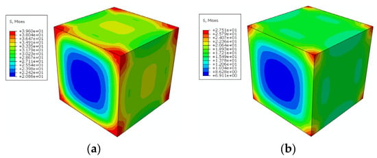
Figure 7.
Comparison of thermal stress after 125 freeze–thaw cycles: (a) plain concrete; and (b) hybrid fiber-reinforced high-strength concrete.
4.5. Compressive Strength Simulation
The axial compression simulation applied full constraints to the bottom of the specimen. All six degrees of freedom were restricted. This setup matched the actual state of a fixed base in the experiment. A reference point was set at the top of the specimen. The loading surface and reference point were bound together via coupling. The applied vertical displacement was uniformly transmitted to the compression surface. A displacement control mode was used during the loading process. The total load was set to 5 mm.
(1) Plain concrete
Figure 8 records the stress evolution of plain concrete under combined loading. In the early stage of the experiment, stress accumulated at the eight corners of the specimen. This is a typical manifestation of freeze–thaw damage. As axial compression loading progressed, stress diffused from the edges to the center. When the pressure reached its peak, the maximum stress value was approximately 39.7 MPa. The stress concentration in local areas was very severe. The concrete had entered the yield state. In the later stage of loading, the external pressure continued. The stress peak dropped rapidly. The specimen, as a whole, showed a trend of softening and strength reduction. Failure began to extend towards the internal core area.
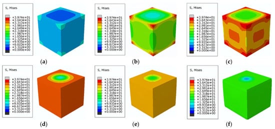
Figure 8.
Mises equivalent stress distribution diagram for plain concrete: (a) initial stage; (b) initiate axial compression loading; (c) mid-term loading; (d) stress reaches its peak; (e) post loading; and (f) end of loading.
(2) Hybrid Fiber-Reinforced High-Strength Concrete
Figure 9 depicts the equivalent stress change of fiber-reinforced concrete. The two materials exhibited a strong synergistic effect. In the initial stage of loading, the matrix stress was transmitted from the edges to the interior. This diffusion range was wider than that of plain concrete. The fibers make the initial stress distribution more uniform. At this point, the pressure on the internal fibers is still at a relatively low level. As displacement increases, the matrix stress in the central region reaches its maximum value. Subsequently, local degradation of the matrix occurs. The fibers begin to bear a large amount of stress at this stage. The fiber stress rises rapidly and approaches the yield limit. The fibers move towards the geometric center. The bridging effect and stress redistribution mechanism begin to take effect. This mechanism replaces the original high-stress path of the matrix. The rapid growth of the macroscopic cracks is suppressed. The ductility and load-bearing capacity of the concrete are improved.
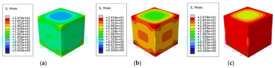
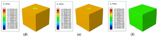
Figure 9.
Equivalent stress distribution in fiber-reinforced concrete matrix: (a) stress inception; (b) stress propagates inward; (c) stress concentration in the core region; (d) local stresses begin to degrade; (e) local stresses gradually decay; and (f) stress reduction.
Simulation data (Figure 10) also confirm the strength of the A3 mix proportion. This material has an initial strength of 68.6 MPa and retains 64.0 MPa after 125 freeze–thaw cycles. The strength only dropped by 4.6 MPa, indicating that the double-fiber admixture can indeed maintain the mechanical properties of HSC.
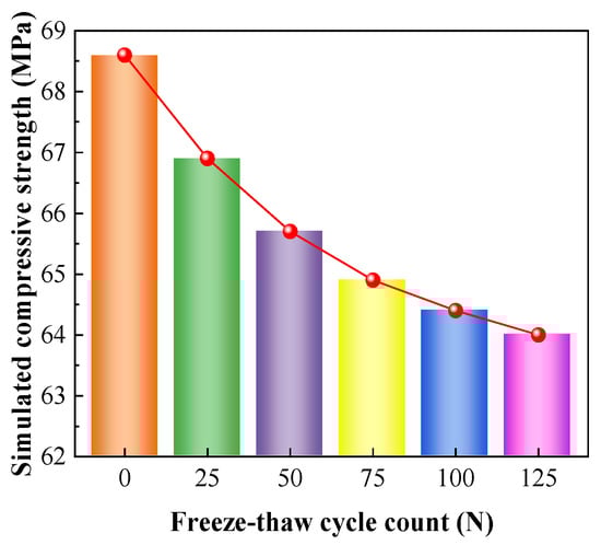
Figure 10.
Compressive strength under different freeze–thaw cycle counts.
(3) Strength Comparison Curve Between Plain Concrete and Hybrid Fiber-Reinforced High-Strength Concrete
The curves in Figure 11 show the relationship between load and displacement. Initially, the trends of both were similar, indicating that the initial hardness mainly depended on the concrete itself. However, once the peak point was reached, the difference became apparent: the curve of plain concrete plummeted, showing brittleness; while the curve of fiber-reinforced concrete declined much more slowly, indicating that it could still support some weight after damage. The data comparison clearly demonstrates a phenomenon: the addition of fibers improves the energy absorption level of concrete under stress. These fibers act like bridges, holding back internal cracks. It is more difficult for the cracks to merge into larger patches within the material. The overall condition of the component is maintained. The entire structure becomes safer under the combined effects of cold and compression. The toughness of the material is also enhanced.
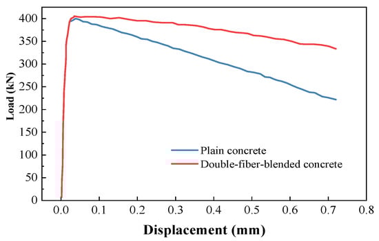
Figure 11.
Load-displacement curve.
5. Conclusions
This study combined experimental and numerical simulation methods. The research object was HSC mixed with SF and PPF. The impact of cold environments on the performance of this concrete was the focus of the study. The changes in fibers directly related to strength reduction and damage. The study yielded the following conclusions:
(1) The mixed use of the two fibers makes the concrete more frost-resistant. After 125 freeze–thaw tests, group A3 performed the best. The dynamic modulus of elasticity of this group remained at 94.5%. Group A0, without fibers, only had 86.5% remaining. The mass loss rate of group A3 was only 1.42%, which is about 41% lower than that of group A0. This reflects the excellent durability of the material;
(2) The data analysis shows that the two fibers work well together. The amount of PPF is closely related to the mass loss. This fiber can prevent the concrete surface from detaching. SF has very high strength. It acts as a tension element in the cracks. The hardness and elasticity of the material are thus protected;
(3) The internal pressure generated by the cold environment was shown to decrease. The overall thermal pressure level was lowered. The fiber dispersed the pressure caused by temperature changes throughout the structure. The failure process was slower. It was more difficult for the damage to expand internally;
(4) The numerical simulation results further quantify the material stability. The simulated residual strength of the A3 group was 64.0 MPa after 125 cycles, compared to an initial modeled strength of 68.6 MPa. This 6.7% strength loss indicates high predicted durability. While plain concrete shows significant brittleness, the modeled fiber-reinforced concrete exhibited a much slower post-peak decline, confirming that this formulation effectively enhances both load-bearing capacity and ductility.
The current analysis mainly focuses on the standard freezing conditions in the laboratory. The engineering site also has the combined effects of salt and water pressure. Future research can include the effects of saltwater freezing and multiple superimposed forces. Researchers can systematically evaluate the long-term performance of this concrete. CT scans can clearly show changes in the internal pores. This helps to understand how fibers work under different temperature differences. These results can provide theoretical support for future concrete formulation design.
Author Contributions
Conceptualization, Y.Z. (Yanchang Zhu); methodology, F.W.; software, Y.T.; validation, Y.F. and Q.W.; resources, Y.Z. (Yanmei Zhang) and C.B.; data curation, Q.Y. and R.Z.; writing—original draft preparation, Y.T.; writing—review and editing, Y.Z. (Yanmei Zhang) and C.Z.; visualization, Y.T.; supervision, Y.Z. (Yanmei Zhang); project administration, C.Z. and Y.Z. (Yanmei Zhang); funding acquisition, C.Z. All authors have read and agreed to the published version of the manuscript.
Funding
This research was funded by Basic Research Business Project of Sichuan Provincial Research Institute (No. 2025-SKY-ZXKY-02).
Data Availability Statement
The original contributions presented in this study are included in the article. Further inquiries can be directed to the corresponding author.
Acknowledgments
The authors would like to express their sincere gratitude to all authors whose work was cited in this study.
Conflicts of Interest
The authors declare no conflicts of interest.
Abbreviations
The following abbreviations are used in this manuscript:
| HSC | High-strength concrete |
| SF | Steel fiber |
| PPF | Polypropylene fiber |
| GGBS | Ground granulated blast-furnace slag |
| CDP | Concrete damage plasticity |
References
- Gan, L.; Xu, W.; Zhang, Z.; Shen, Z.; Liu, J.; Feng, X. Macro–microscopic experimental and numerical simulation study of fiber-mixed concrete under the salt–freezing effect. J. Build. Eng. 2024, 82, 108371. [Google Scholar] [CrossRef]
- Miao, P.; Wei, C.; Wang, W.; Qu, C.; Wu, Y.; Wang, Z.; Srimahachota, T. Performance assessment of fiber-reinforced PCM for coastal concrete bridge repairs from material to structural level. Constr. Build. Mater. 2025, 490, 142617. [Google Scholar] [CrossRef]
- Qin, X.; Huang, X.; Kaewunruen, S. Time-dependent reliability assessment and durability analysis of industrial and recycled steel fiber reinforced concrete beams. Eng. Struct. 2025, 336, 120442. [Google Scholar] [CrossRef]
- Guo, S.; Yu, T.; Mao, K.; Cao, P.; Lu, J.; Zhong, H. Study on fracture properties and damage of glass fiber reinforced concrete under corrosive environment. Constr. Build. Mater. 2025, 501, 144238. [Google Scholar] [CrossRef]
- Menaka, K.; Bhuvaneshwari, M. Response Surface Optimization of Palm Oil Fuel Ash Concrete Reinforced with Kenaf Fibers. Case Stud. Constr. Mater. 2025, 23, e05331. [Google Scholar] [CrossRef]
- Zhao, C.; Jiang, G.; Guo, J.; Zhang, X.; Ma, Z.; Zhuang, C.; Zhang, W.; Yu, S. Experimental Investigation on the Frost Resistance and Service Life Prediction of Basalt Fiber-Reinforced Concrete. Fibers 2025, 13, 143. [Google Scholar] [CrossRef]
- Gao, D.; Zhang, W.; Gu, Z.; Hu, Y.; Yang, Z.; Yang, L. Investigation on shear performance of steel fiber reinforced recycled concrete short beams. Constr. Build. Mater. 2025, 497, 143873. [Google Scholar] [CrossRef]
- Smarzewski, P. Mechanical properties and durability of ultra-high performance concrete containing steel fibers. Compos. Struct. 2025, 371, 119471. [Google Scholar] [CrossRef]
- Ahmad, J.; Burduhos-Nergis, D.D.; Arbili, M.M.; Alogla, S.M.; Majdi, A.; Deifalla, A.F. A review on failure modes and cracking behaviors of polypropylene fibers reinforced concrete. Buildings 2022, 12, 1951. [Google Scholar] [CrossRef]
- Gong, L.; Yu, X.; Liang, Y.; Gong, X.; Du, Q. Multi-scale deterioration and microstructure of polypropylene fiber concrete by salt freezing. Case Stud. Constr. Mater. 2023, 18, e01762. [Google Scholar] [CrossRef]
- Wang, S.; Xu, L.; Chi, Y.; Cui, K.; Yin, C.; Li, B. Cyclic tensile behavior of ultra-high performance concrete with hybrid steel-polypropylene fiber: Experimental study and analytical model. Compos. Struct. 2023, 321, 117255. [Google Scholar] [CrossRef]
- Khaleel Ibrahim, S.; Abbas Hadi, N.; Movahedi Rad, M. Experimental and numerical analysis of steel-polypropylene hybrid fibre reinforced concrete deep beams. Polymers 2023, 15, 2340. [Google Scholar] [CrossRef] [PubMed]
- Gu, G.; Yuan, K.; Li, S.; Al-Mansour, A.; Fu, C.; Zhong, Q.; Xiong, H.; Chen, J. Synergistic effects of steel-polypropylene hybrid fibers on bond-slip behavior of deformed rebars in concrete. J. Build. Eng. 2025, 114, 114356. [Google Scholar] [CrossRef]
- Hosseinzadeh, H.; Salehi, A.M.; Mehraein, M.; Asadollahfardi, G. The effects of steel, polypropylene, and high-performance macro polypropylene fibers on mechanical properties and durability of high-strength concrete. Constr. Build. Mater. 2023, 386, 131589. [Google Scholar] [CrossRef]
- Rashid, M.U. Experimental investigation on durability characteristics of steel and polypropylene fiber reinforced concrete exposed to natural weathering action. Constr. Build. Mater. 2020, 250, 118910. [Google Scholar] [CrossRef]
- Wang, Y.; Zhang, S.; Niu, D.; Fu, Q. Quantitative evaluation of the characteristics of air voids and their relationship with the permeability and salt freeze–thaw resistance of hybrid steel-polypropylene fiber–reinforced concrete composites. Cem. Concr. Compos. 2022, 125, 104292. [Google Scholar] [CrossRef]
- Li, Y.; Zheng, Z.; Zhang, Y.; Li, B.; Fan, X. Effect of steel-polypropylene hybrid fiber on the flexural behavior of RC beams under cryogenic freeze–thaw cycles and repeated loading. Eng. Fail. Anal. 2025, 170, 109236. [Google Scholar] [CrossRef]
- Pan, K.; Ma, C.; Rena, C.Y.; Wu, Z. Multi-index evaluation of steel fiber’s crack resistance enhancement in desert sand concrete under freeze-thaw cycles: Optimization, fracture, and mechanism. Constr. Build. Mater. 2025, 499, 144059. [Google Scholar] [CrossRef]
- Wu, J.; Liu, K.; Wang, S.; Quan, X.; Tian, P.; Tian, Z.; Ying, H. Evaluation of hybrid steel-polyethylene fiber-reinforced aggregated solid waste cementitious composites subjected to seawater freeze-thaw cycles attack: Durability, 3D pore structure, and microstructure. Constr. Build. Mater. 2025, 493, 143069. [Google Scholar] [CrossRef]
- Gan, L.; Liu, G.; Liu, J.; Zhang, H.; Feng, X.; Li, L. Three-dimensional microscale numerical simulation of fiber-reinforced concrete under sulfate freeze-thaw action. Case Stud. Constr. Mater. 2024, 20, e03308. [Google Scholar] [CrossRef]
- Miao, H.; Guo, C.; Lu, Z.; Chen, Z. 3D mesoscale analysis of concrete containing defect damages during different freeze-thaw cycles. Constr. Build. Mater. 2022, 358, 129449. [Google Scholar] [CrossRef]
- Zhu, Y.; Bu, C.; Zhang, Y. Research on the mix proportion design and mechanical properties of C60 hybrid fiber-reinforced high-strength concrete. ce/papers 2025, 8, 66–81. [Google Scholar] [CrossRef]
- GB/T 50082-2024; Standard Test Methods for Long-Term Performance and Durability of Concrete. China Architecture & Building Press, Ministry of Housing and Urban-Rural Development of the People’s Republic of China: Beijing, China, 2024; pp. 10–14.
- Fakeh, M.; Jawdhari, A.; Fam, A. Recommended concrete damage plasticity parameters and constitutive models for UHPC in ABAQUS. Eng. Struct. 2025, 333, 120154. [Google Scholar] [CrossRef]
- Xu, S.; Liu, J.; Li, L.; Zhang, G.; Li, Y. Strength prediction of freeze-thaw geopolymer concrete considering pores characteristics: Experiment and three-dimensional meso-numerical simulation. Constr. Build. Mater. 2025, 493, 143131. [Google Scholar] [CrossRef]
- Lian, S.; Huang, J.; Wan, W.; Zhao, Y.; Wang, W.; Wang, X.; Wu, Q. Study on the mechanical behavior of basalt-polypropylene fiber concrete: Insights from Experimental Testing and Numerical Simulation. Case Stud. Constr. Mater. 2025, 24, e05746. [Google Scholar] [CrossRef]


Disclaimer/Publisher’s Note: The statements, opinions and data contained in all publications are solely those of the individual author(s) and contributor(s) and not of MDPI and/or the editor(s). MDPI and/or the editor(s) disclaim responsibility for any injury to people or property resulting from any ideas, methods, instructions or products referred to in the content. |
© 2026 by the authors. Licensee MDPI, Basel, Switzerland. This article is an open access article distributed under the terms and conditions of the Creative Commons Attribution (CC BY) license.