
Application of Graphene Nanoplatelets in Supercapacitor Devices: A Review of Recent Developments


Abstract
1. Introduction
2. Background on Supercapacitor Technologies
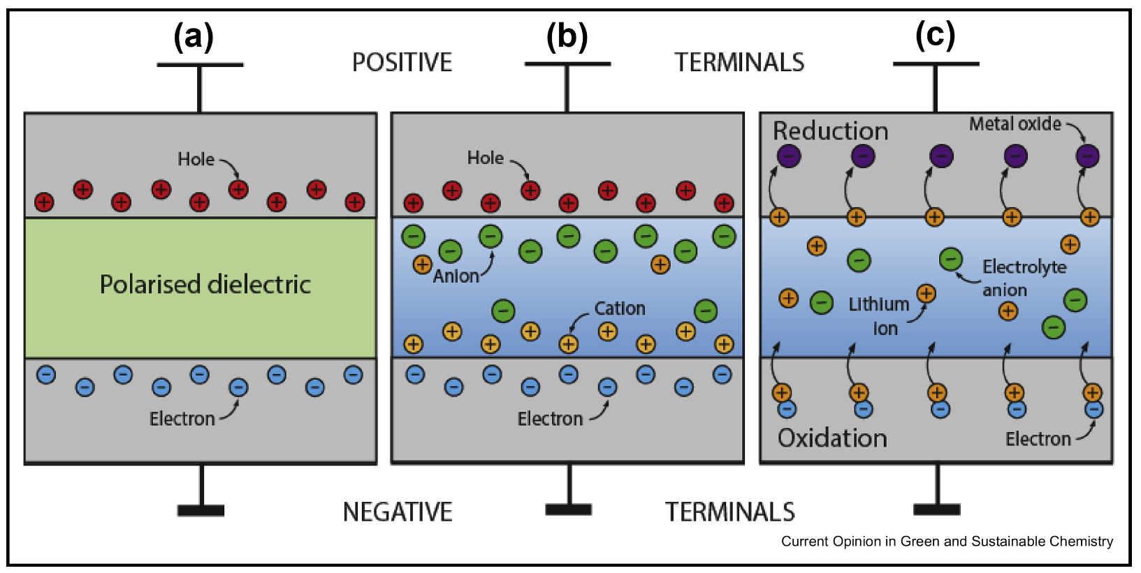
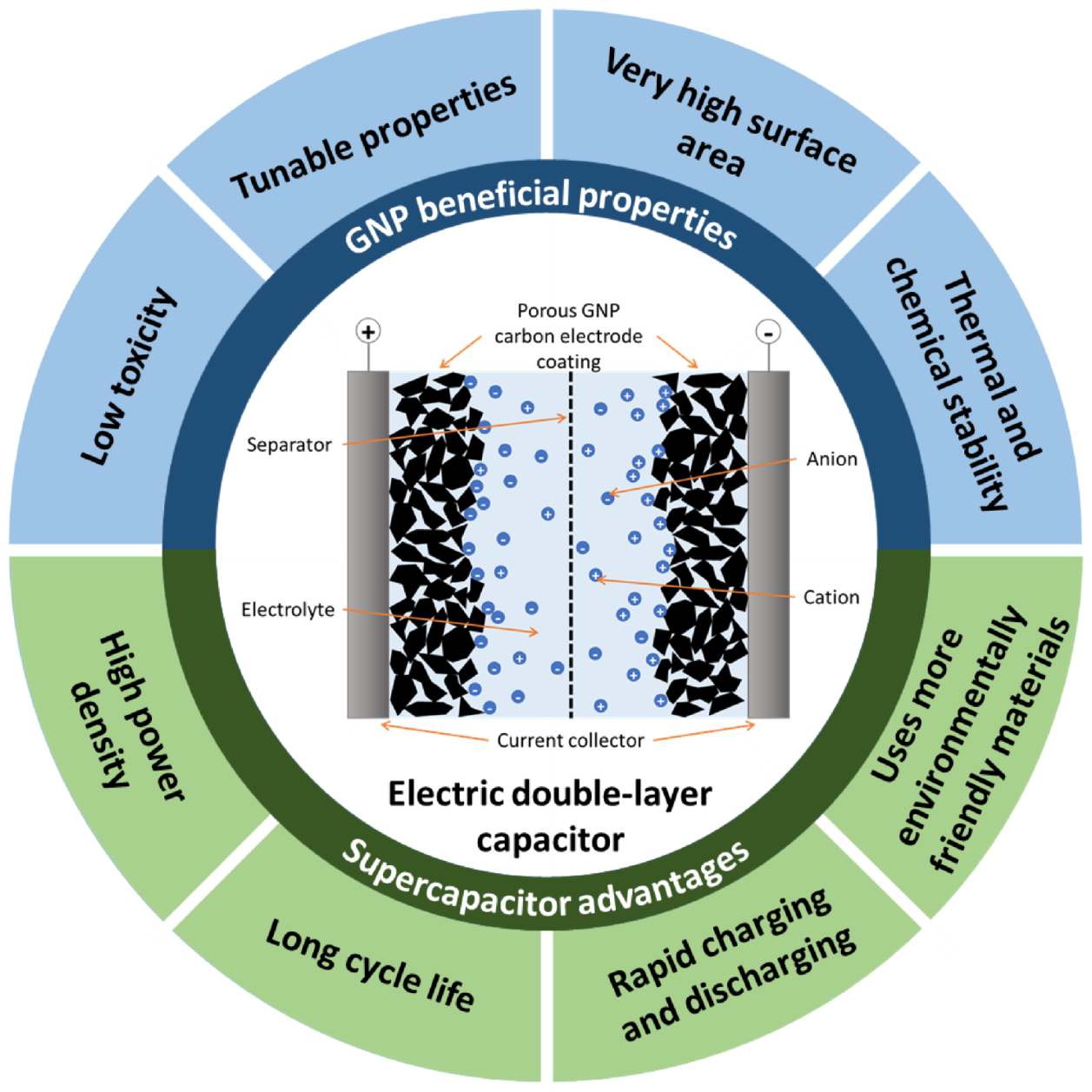
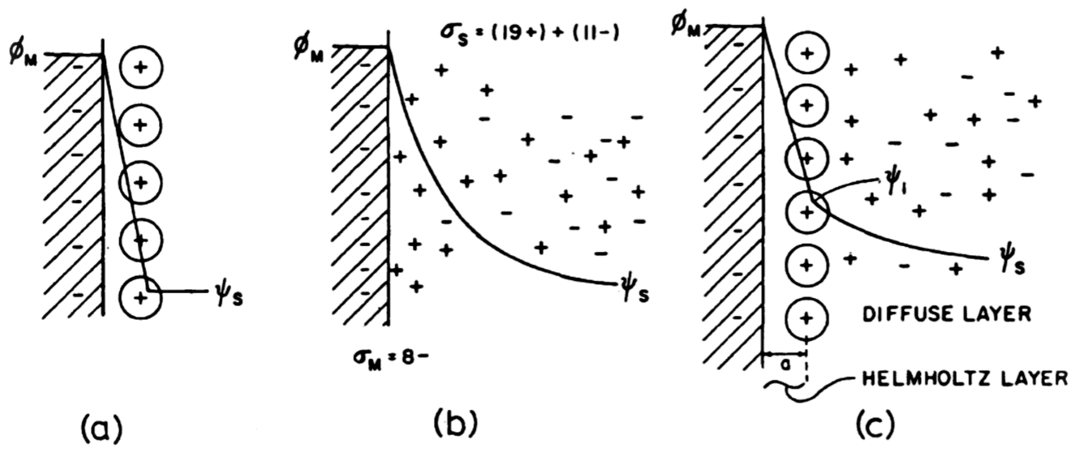
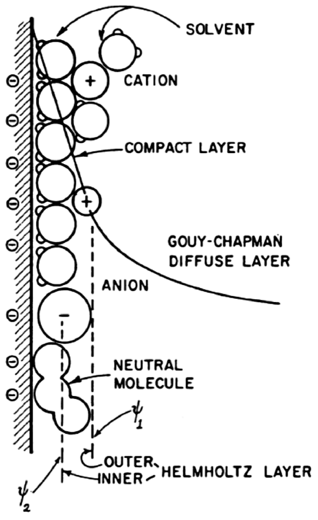
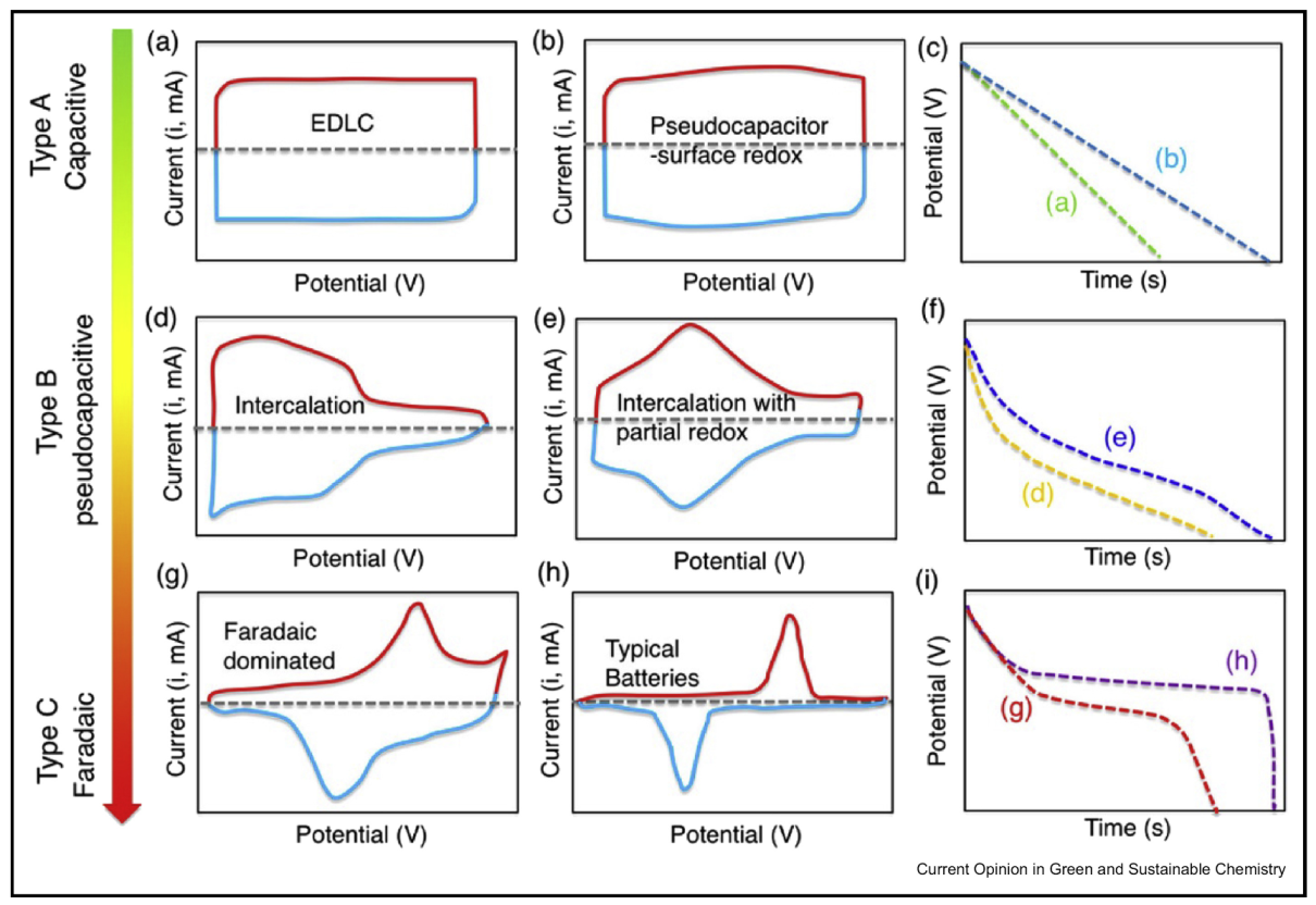
2.1. Electric Double-Layer Capacitance
2.2. Pseudocapacitance
2.3. Electrode Material Selection
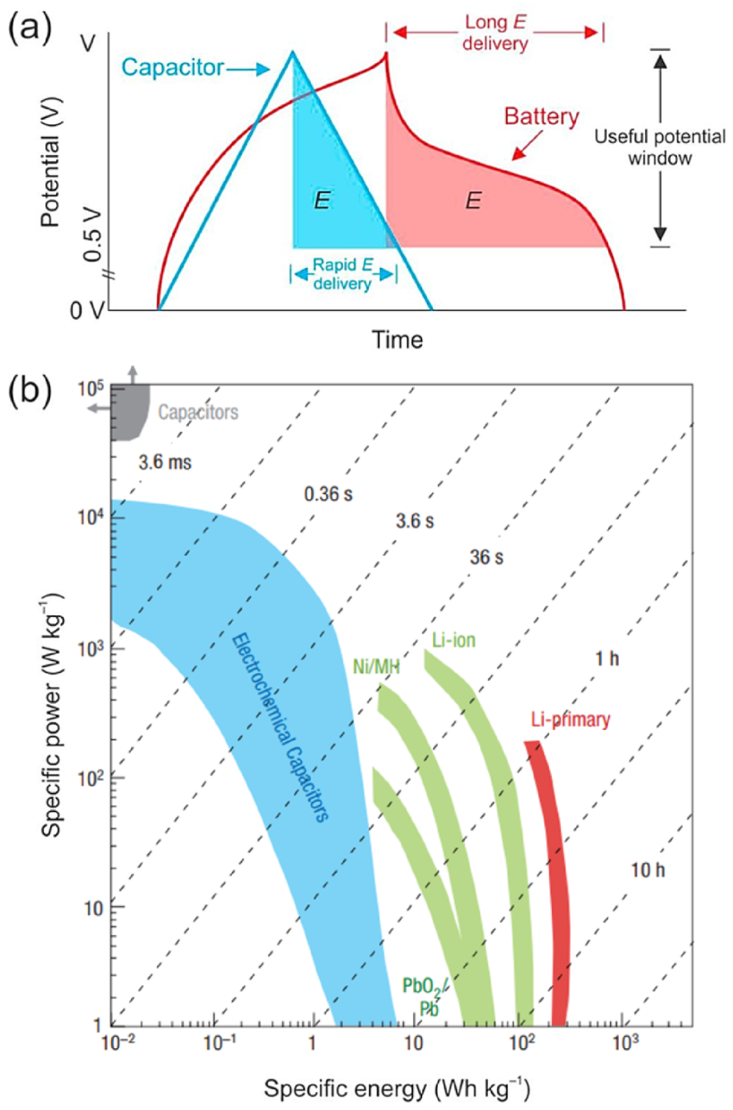
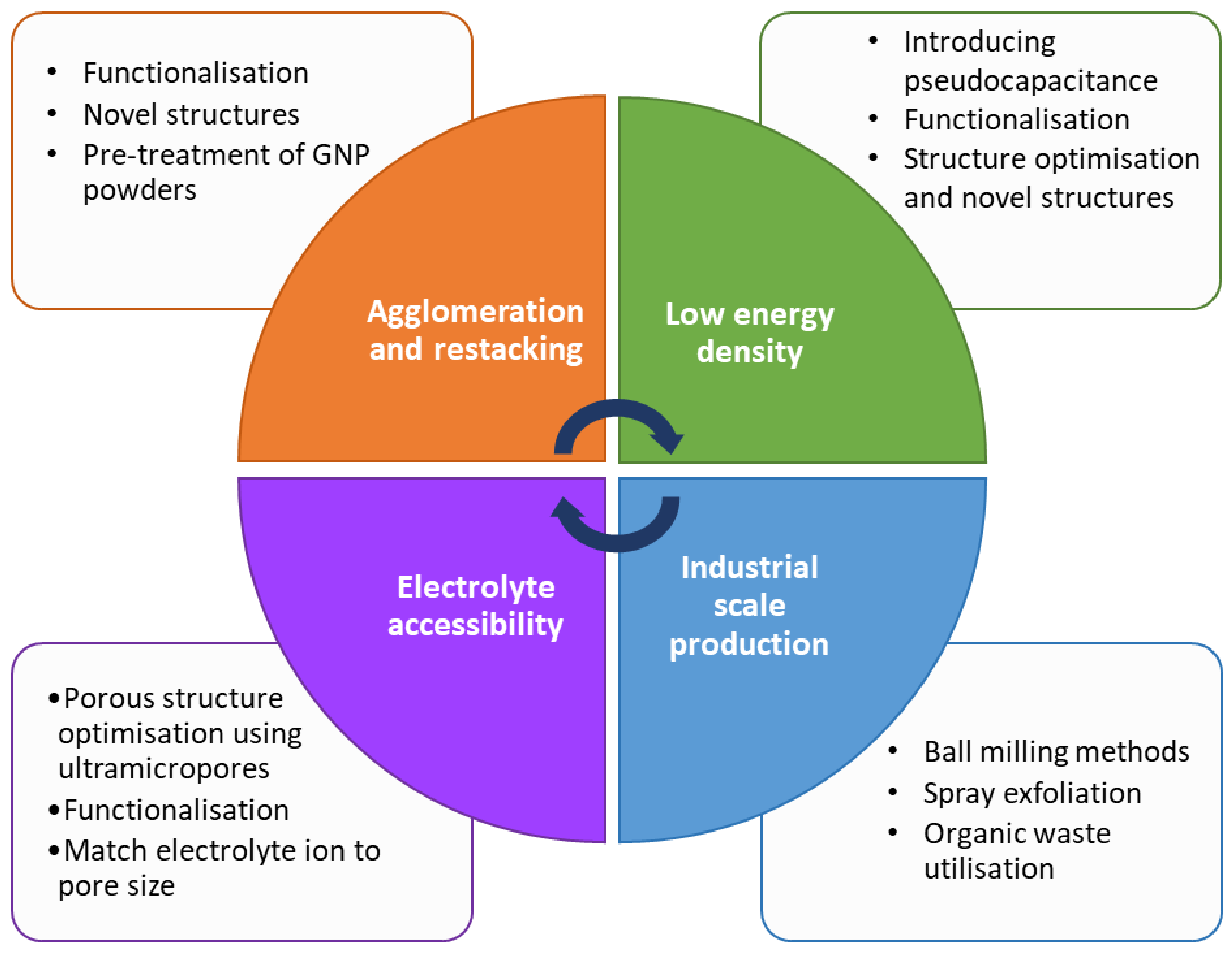
2.4. Drawbacks of Conventional Supercapacitors
- Low energy density,
- Limited specific capacitance and operating voltage,
- Poor electrolyte accessibility,
- Porous structure optimisation,
- Agglomeration of carbon nanomaterials,
- Difficulty with industrial scale production.
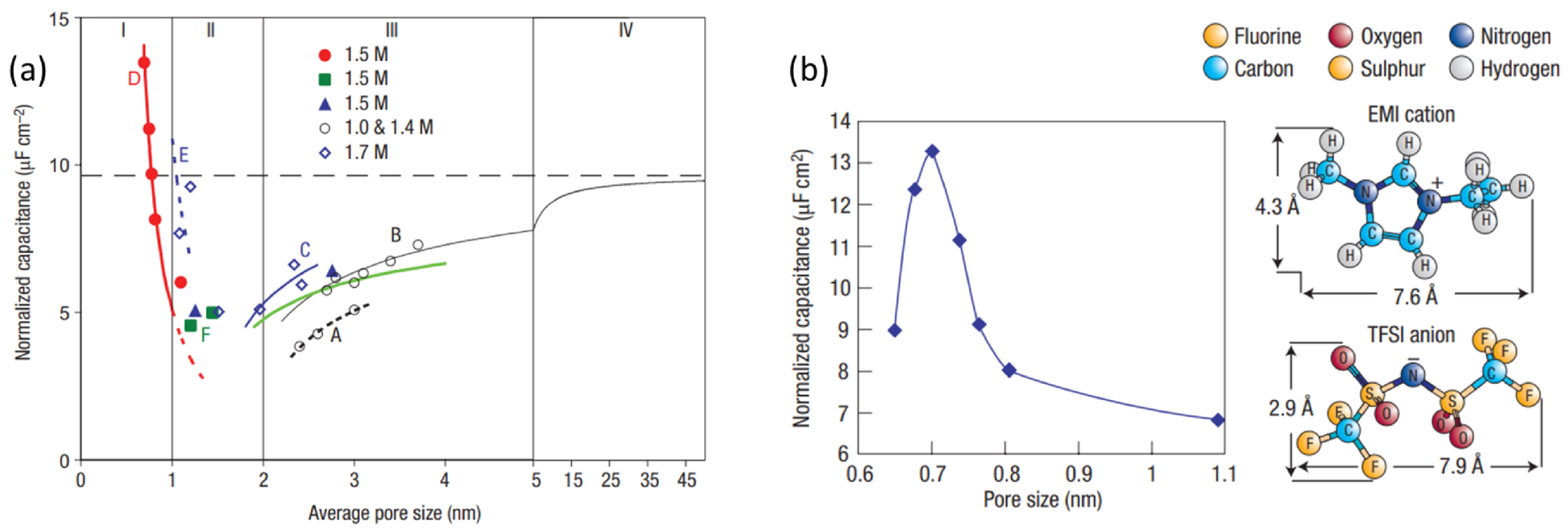
2.5. The Effect of Porous Structure
3. Recent Progress in GNP Supercapacitors
3.1. Plain GNPs
3.2. Functionalised GNP Supercapacitors
3.2.1. Pseudocapacitive Functionalisation
3.2.2. Carboxyl Functionalisation
3.2.3. Hydroxyl Functionalisation
3.2.4. Other Functionalisations
4. Conclusions and Perspectives
Author Contributions
Funding
Institutional Review Board Statement
Informed Consent Statement
Data Availability Statement
Conflicts of Interest
Abbreviations
| AC | Activated carbon |
| BET | Brunauer-Emmett-Teller |
| CDC | Carbide-derived carbons |
| CNT | Carbon nanotube |
| CV | Cyclic voltammetry |
| EDL | Electric double-layer |
| EDLC | Electric double-layer capacitor |
| FLG | Few layer graphene |
| GCD | Galvanostatic charge-discharge |
| GNP | Graphene nanoplatelets |
| LIB | Lithium-ion battery |
| SSA | Specific surface area |
References
- Xiang, Z.; Dai, Q.; Chen, J.F.; Dai, L. Edge Functionalization of Graphene and Two-Dimensional Covalent Organic Polymers for Energy Conversion and Storage. Adv. Mater. 2016, 28, 6253–6261. [Google Scholar] [CrossRef] [PubMed]
- Wang, Y.; Zhang, L.; Hou, H.; Xu, W.; Duan, G.; He, S.; Liu, K.; Jiang, S. Recent progress in carbon-based materials for supercapacitor electrodes: A review. J. Mater. Sci. 2020, 56, 173–200. [Google Scholar] [CrossRef]
- Conway, B.E. Electrochemical Supercapacitors: Scientific Fundamentals and Technological Applications; Springer: New York, NY, USA, 1999. [Google Scholar] [CrossRef]
- Horn, M.; Gupta, B.; MacLeod, J.; Liu, J.; Motta, N. Graphene-based supercapacitor electrodes: Addressing challenges in mechanisms and materials. Curr. Opin. Green Sustain. Chem. 2019, 17, 42–48. [Google Scholar] [CrossRef]
- Horn, M.; MacLeod, J.; Liu, M.; Webb, J.; Motta, N. Supercapacitors: A new source of power for electric cars? Econ. Anal. Policy 2019, 61, 93–103. [Google Scholar] [CrossRef]
- Hu, Y. Carbon and Metal Oxides Based Nanomaterials for Flexible High Performance Asymmetric Supercapacitors. Ph.D. Thesis, National University of Singapore, Singapore, 2018. [Google Scholar] [CrossRef]
- Bokhari, S.W.; Siddique, A.H.; Sherrell, P.C.; Yue, X.; Karumbaiah, K.M.; Wei, S.; Ellis, A.V.; Gao, W. Advances in graphene-based supercapacitor electrodes. Energy Rep. 2020, 6, 2768–2784. [Google Scholar] [CrossRef]
- Borenstein, A.; Hanna, O.; Attias, R.; Luski, S.; Brousse, T.; Aurbach, D. Carbon-based composite materials for supercapacitor electrodes: A review. J. Mater. Chem. A 2017, 5, 12653–12672. [Google Scholar] [CrossRef]
- Becker, H. Low Voltage Electrolytic Capacitor. U.S. Patent Number US 2800616 A, 23 July 1957. [Google Scholar]
- Liu, Z.; Zhang, S.; Wang, L.; Wei, T.; Qiu, Z.; Fan, Z. High-efficiency utilization of carbon materials for supercapacitors. Nano Sel. 2020, 1, 244–262. [Google Scholar] [CrossRef]
- Lin, Z.; Goikolea, E.; Balducci, A.; Naoi, K.; Taberna, P.L.; Salanne, M.; Yushin, G.; Simon, P. Materials for supercapacitors: When Li-ion battery power is not enough. Mater. Today 2018, 21, 419–436. [Google Scholar] [CrossRef]
- Kostoglou, N.; Tarat, A.; Walters, I.; Ryzhkov, V.; Tampaxis, C.; Charalambopoulou, G.; Steriotis, T.; Mitterer, C.; Rebholz, C. Few-layer graphene-like flakes derived by plasma treatment: A potential material for hydrogen adsorption and storage. Microporous Mesoporous Mater. 2016, 225, 482–487. [Google Scholar] [CrossRef]
- Chernysh, O.; Makyeyeva, I.; Khomenko, V.; Barsukov, V. Alternative binders for electrodes of electrochemical capacitors: The transition to aqueous and alcohol based solvent electrode processing. Mater. Today Proc. 2022, 50, 419–422. [Google Scholar] [CrossRef]
- Moniruzzaman, M.; Akib, A.; Shakil, R.; Khatun, S.; Kumar Roy, C.; Chowdury, A.N. Influence of Binder in the Fabrication of AC-Based High-Performance Electrochemical Supercapacitors. ECS Trans. 2022, 107, 18357–18365. [Google Scholar] [CrossRef]
- Ravikumar, V.R.; Schröder, A.; Köhler, S.; Çetinel, F.A.; Schmitt, M.; Kondrakov, A.; Eberle, F.; Eichler-Haeske, J.O.; Klein, D.; Schmidt-Hansberg, B. γ-Valerolactone: An Alternative Solvent for Manufacturing of Lithium-Ion Battery Electrodes. ACS Appl. Energy Mater. 2021, 4, 696–703. [Google Scholar] [CrossRef]
- Chen, F.; Zhao, Y.; Zhou, Y.; Xu, J.; Yang, Y.; Yang, W. Effect of solvent on the energy storage property of poly(vinylidene fluoride-hexafluoropropylene). Mater. Res. Express 2020, 7, 015323. [Google Scholar] [CrossRef]
- Rajeevan, S.; John, S.; George, S.C. Polyvinylidene fluoride: A multifunctional polymer in supercapacitor applications. J. Power Sources 2021, 504, 230037. [Google Scholar] [CrossRef]
- Loganathan, N.N.; Perumal, V.; Pandian, B.R.; Atchudan, R.; Edison, T.N.J.I.; Ovinis, M. Recent studies on polymeric materials for supercapacitor development. J. Energy Storage 2022, 49, 104149. [Google Scholar] [CrossRef]
- Cetinkaya, T.; Dryfe, R.A. Electrical double layer supercapacitors based on graphene nanoplatelets electrodes in organic and aqueous electrolytes: Effect of binders and scalable performance. J. Power Sources 2018, 408, 91–104. [Google Scholar] [CrossRef]
- Nasrin, K.; Gokulnath, S.; Karnan, M.; Subramani, K.; Sathish, M. Redox-Additives in Aqueous, Non-Aqueous, and All-Solid-State Electrolytes for Carbon-Based Supercapacitor: A Mini-Review. Energy Fuels 2021, 35, 6465–6482. [Google Scholar] [CrossRef]
- Ali, B.A.; Biby, A.H.; Allam, N.K. Toward the Proper Selection of Carbon Electrode Materials for Energy Storage Applications: Experimental and Theoretical Insights. Energy Fuels 2021, 35, 13426–13437. [Google Scholar] [CrossRef]
- Pal, B.; Yang, S.; Ramesh, S.; Thangadurai, V.; Jose, R. Electrolyte selection for supercapacitive devices: A critical review. Nanoscale Adv. 2019, 1, 3807–3835. [Google Scholar] [CrossRef]
- Gao, Q. Optimizing carbon/carbon supercapacitors in aqueous alkali sulfates electrolytes. J. Energy Chem. 2019, 38, 219–224. [Google Scholar] [CrossRef]
- Zhang, D.; Yang, B.; She, W.; Gao, S.; Wang, J.; Wang, Y.; Wang, K.; Li, H.; Han, L. Simultaneously achieving high energy and power density for ultrafast-charging supercapacitor built by a semi-graphitic hierarchical porous carbon nanosheet and a high-voltage alkaline aqueous electrolyte. J. Power Sources 2021, 506, 230103. [Google Scholar] [CrossRef]
- Roy, C.K.; Shah, S.S.; Reaz, A.H.; Sultana, S.; Chowdhury, A.N.; Firoz, S.H.; Zahir, M.H.; Ahmed Qasem, M.A.; Aziz, M.A. Preparation of Hierarchical Porous Activated Carbon from Banana Leaves for High-performance Supercapacitor: Effect of Type of Electrolytes on Performance. Chem. Asian J. 2021, 16, 296–308. [Google Scholar] [CrossRef]
- Sajjad, M.; Khan, M.I.; Cheng, F.; Lu, W. A review on selection criteria of aqueous electrolytes performance evaluation for advanced asymmetric supercapacitors. J. Energy Storage 2021, 40, 102729. [Google Scholar] [CrossRef]
- Luo, Z.; Wang, X.; Chen, D.; Chang, Q.; Xie, S.; Ma, Z.; Lei, W.; Pan, J.; Pan, Y.; Huang, J. Ultrafast Li/Fluorinated Graphene Primary Batteries with High Energy Density and Power Density. ACS Appl. Mater. Interfaces 2021, 13, 18809–18820. [Google Scholar] [CrossRef]
- Zhong, G.; Chen, H.; Huang, X.; Yue, H.; Lu, C. High-power-density, high-energy-density fluorinated graphene for primary lithium batteries. Front. Chem. 2018, 6, 50. [Google Scholar] [CrossRef]
- Gencten, M.; Sahin, Y. A critical review on progress of the electrode materials of vanadium redox flow battery. Int. J. Energy Res. 2020, 44, 7903–7923. [Google Scholar] [CrossRef]
- Yu, S.; Guo, B.; Zeng, T.; Qu, H.; Yang, J.; Bai, J. Graphene-based lithium-ion battery anode materials manufactured by mechanochemical ball milling process: A review and perspective. Compos. Part Eng. 2022, 246, 110232. [Google Scholar] [CrossRef]
- Uemura, Y.; Chen, C.Y.; Hashimoto, Y.; Tsuda, T.; Matsumoto, H.; Kuwabata, S. Graphene Nanoplatelet Composite Cathode for a Chloroaluminate Ionic Liquid-Based Aluminum Secondary Battery. ACS Appl. Energy Mater. 2018, 1, 2269–2274. [Google Scholar] [CrossRef]
- Fan, Q.; Noh, H.J.; Wei, Z.; Zhang, J.; Lian, X.; Ma, J.; Jung, S.M.; Jeon, I.Y.; Xu, J.; Baek, J.B. Edge-thionic acid-functionalized graphene nanoplatelets as anode materials for high-rate lithium ion batteries. Nano Energy 2019, 62, 419–425. [Google Scholar] [CrossRef]
- Adepoju, A.A.; Doumbia, M.; Williams, Q.L. Graphene Nanoplatelet Additives for High C-rate LiFePO4 Battery Cathodes. JOM 2020, 72, 3170–3175. [Google Scholar] [CrossRef]
- Esteve-Adell, I.; Porcel-Valenzuela, M.; Zubizarreta, L.; Gil-Agustí, M.; García-Pellicer, M.; Quijano-Lopez, A. Influence of the Specific Surface Area of Graphene Nanoplatelets on the Capacity of Lithium-Ion Batteries. Front. Chem. 2022, 10, 807980. [Google Scholar] [CrossRef] [PubMed]
- Averianov, T.; Pomerantseva, E. Composite Li-ion battery cathodes formed via integration of carbon nanotubes or graphene nanoplatelets into chemical preintercalation synthesis of bilayered vanadium oxides. J. Alloys Compd. 2022, 903, 163929. [Google Scholar] [CrossRef]
- Helmholtz, H. Ueber einige Gesetze der Vertheilung elektrischer Ströme in körperlichen Leitern mit Anwendung auf die thierisch-elektrischen Versuche. Ann. Phys. 1853, 165, 211–233. [Google Scholar] [CrossRef]
- Banda, H.; Pe, S.; Daffos, B.; Taberna, P.L.; Dubois, L.; Crosnier, O.; Simon, P.; Lee, D.; Pae, D.; Duclairoir, F. Sparsely Pillared Graphene Materials for High-Performance Supercapacitors: Improving Ion Transport and Storage Capacity. ACS Nano 2019, 13, 1443–1453. [Google Scholar] [CrossRef] [PubMed]
- Simon, P.; Gogotsi, Y. Materials for electrochemical capacitors. In Nanoscience and Technology: A Collection of Reviews from Nature Journals; World Scientific Publishing Co.: Singapore, 2009; pp. 320–329. [Google Scholar] [CrossRef]
- Bakandritsos, A.; Jakubec, P.; Pykal, M.; Otyepka, M. Covalently functionalized graphene as a supercapacitor electrode material. FlatChem 2019, 13, 25–33. [Google Scholar] [CrossRef]
- Shao, H.; Wu, Y.C.; Lin, Z.; Taberna, P.L.; Simon, P. Nanoporous carbon for electrochemical capacitive energy storage. Chem. Soc. Rev. 2020, 49, 3005–3039. [Google Scholar] [CrossRef]
- Redkin, A.N.; Mitina, A.A.; Yakimov, E.E. Simple technique of multiwalled carbon nanotubes growth on aluminum foil for supercapacitors. Mater. Sci. Eng. B 2021, 272, 115342. [Google Scholar] [CrossRef]
- Novoselov, K.S.; Geim, A.K.; Morozov, S.V.; Jiang, D.; Zhang, Y.; Dubonos, S.V.; Grigorieva, I.V.; Firsov, A.A. Electric field in atomically thin carbon films. Science 2004, 306, 666–669. [Google Scholar] [CrossRef]
- Velasco, A.; Ryu, Y.K.; Boscá, A.; Ladrón-De-Guevara, A.; Hunt, E.; Zuo, J.; Pedrós, J.; Calle, F.; Martinez, J. Recent trends in graphene supercapacitors: From large area to microsupercapacitors. Sustain. Energy Fuels 2021, 5, 1235–1254. [Google Scholar] [CrossRef]
- Lakra, R.; Kumar, R.; Sahoo, P.K.; Thatoi, D.; Soam, A. A mini-review: Graphene based composites for supercapacitor application. Inorg. Chem. Commun. 2021, 133, 108929. [Google Scholar] [CrossRef]
- Okenwa, C.; Aigbodion, V.S.; Offor, P.O. High performance supercapacitor active electrode material by drop-casting of graphite and graphene synthesized from rice husk. Int. J. Adv. Manuf. Technol. 2022, 1–8. [Google Scholar] [CrossRef]
- Edison, T.N.J.I.; Atchudan, R.; Karthik, N.; Chandrasekaran, P.; Perumal, S.; Arunachalam, P.; Raja, P.B.; Sethuraman, M.G.; Lee, Y.R. Electrochemically exfoliated graphene sheets as electrode material for aqueous symmetric supercapacitors. Surf. Coat. Technol. 2021, 416, 127–150. [Google Scholar] [CrossRef]
- Shaikh, J.S.; Shaikh, N.S.; Mishra, Y.K.; Pawar, S.S.; Parveen, N.; Shewale, P.M.; Sabale, S.; Kanjanaboos, P.; Praserthdam, S.; Lokhande, C.D. The implementation of graphene-based aerogel in the field of supercapacitor. Nanotechnology 2021, 32, 362001. [Google Scholar] [CrossRef] [PubMed]
- Lee, S.P.; Ali, G.A.; Hegazy, H.H.; Lim, H.N.; Chong, K.F. Optimizing Reduced Graphene Oxide Aerogel for a Supercapacitor. Energy Fuels 2021, 35, 4559–4569. [Google Scholar] [CrossRef]
- Xu, M.; Wang, A.; Xiang, Y.; Niu, J. Biomass-based porous carbon/graphene self-assembled composite aerogels for high-rate performance supercapacitor. J. Clean. Prod. 2021, 315, 128110. [Google Scholar] [CrossRef]
- Xu, X.; Zhou, J.; Jestin, J.; Colombo, V.; Lubineau, G. Preparation of water-soluble graphene nanoplatelets and highly conductive films. Carbon 2017, 124, 133–141. [Google Scholar] [CrossRef]
- Pullini, D.; Siong, V.; Tamvakos, D.; Lobato Ortega, B.; Sgroi, M.F.; Veca, A.; Glanz, C.; Kolaric, I.; Pruna, A. Enhancing the capacitance and active surface utilization of supercapacitor electrode by graphene nanoplatelets. Compos. Sci. Technol. 2015, 112, 16–21. [Google Scholar] [CrossRef]
- Yu, A.; Sy, A.; Davies, A. Graphene nanoplatelets supported MnO2 nanoparticles for electrochemical supercapacitor. Synth. Met. 2011, 161, 2049–2054. [Google Scholar] [CrossRef]
- Deb Nath, N.C.; Jeon, I.Y.; Ju, M.J.; Ansari, S.A.; Baek, J.B.; Lee, J.J. Edge-carboxylated graphene nanoplatelets as efficient electrode materials for electrochemical supercapacitors. Carbon 2019, 142, 89–98. [Google Scholar] [CrossRef]
- Purkait, T.; Singh, G.; Singh, M.; Kumar, D.; Dey, R.S. Large area few-layer graphene with scalable preparation from waste biomass for high-performance supercapacitor. Sci. Rep. 2017, 7, 15239. [Google Scholar] [CrossRef]
- Pachfule, P.; Shinde, D.; Majumder, M.; Xu, Q. Fabrication of carbon nanorods and graphene nanoribbons from a metal-organic framework. Nat. Chem. 2016, 8, 718–724. [Google Scholar] [CrossRef] [PubMed]
- Pandey, S.; Karakoti, M.; Surana, K.; Dhapola, P.S.; SanthiBhushan, B.; Ganguly, S.; Singh, P.K.; Abbas, A.; Srivastava, A.; Sahoo, N.G. Graphene nanosheets derived from plastic waste for the application of DSSCs and supercapacitors. Sci. Rep. 2021, 11, 3916. [Google Scholar] [CrossRef]
- Banavath, R.; Nemala, S.S.; Kim, S.H.; Bohm, S.; Ansari, M.Z.; Mohapatra, D.; Bhargava, P. Industrially scalable exfoliated graphene nanoplatelets by high-pressure airless spray technique for high-performance supercapacitors. FlatChem 2022, 33, 100373. [Google Scholar] [CrossRef]
- Xu, X.; Lai, R.; Jiang, C.; Zhang, W.; Liu, L.; Cao, G. Self-propagating combustion synthesis of few-layer graphene for supercapacitors from CO and Mg. J. Alloys Compd. 2022, 908, 164652. [Google Scholar] [CrossRef]
- Chiam, S.L.; Lim, H.N.; Hafiz, S.M.; Pandikumar, A.; Huang, N.M. Electrochemical Performance of Supercapacitor with Stacked Copper Foils Coated with Graphene Nanoplatelets. Sci. Rep. 2018, 8, 3093. [Google Scholar] [CrossRef]
- Young, C.; Lin, J.; Wang, J.; Ding, B.; Zhang, X.; Alshehri, S.M.; Ahamad, T.; Salunkhe, R.R.; Hossain, S.A.; Khan, J.H.; et al. Significant Effect of Pore Sizes on Energy Storage in Nanoporous Carbon Supercapacitors. Chem. Eur. J. 2018, 24, 6127–6132. [Google Scholar] [CrossRef]
- Chmiola, J.; Yushin, G.; Gogotsi, Y.; Portet, C.; Simon, P.; Taberna, P.L. Anomalous increase in carbon at pore sizes less than 1 nanometer. Science 2006, 313, 1760–1763. [Google Scholar] [CrossRef]
- Raymundo-Piñero, E.; Kierzek, K.; Machnikowski, J.; Béguin, F. Relationship between the nanoporous texture of activated carbons and their capacitance properties in different electrolytes. Carbon 2006, 44, 2498–2507. [Google Scholar] [CrossRef]
- Bi, S.; Li, Z.; Xiao, D.; Li, Z.; Mo, T.; Feng, G.; Zhang, X. Pore-Size-Dependent Capacitance and Charging Dynamics of Nanoporous Carbons in Aqueous Electrolytes. J. Phys. Chem. C 2022, 126, 6854–6862. [Google Scholar] [CrossRef]
- Chen, J.; Chen, S.; Chen, B.; Cao, Y.; Chen, J.; Cheng, Y.; Chen, Z.; Fu, J. Ultrathin microporous carbon/few-layer graphene heterostructure for supercapacitor application. Appl. Surf. Sci. 2022, 590, 153156. [Google Scholar] [CrossRef]
- Kim, B.M.; Kim, H.Y.; Hong, S.W.; Choi, W.H.; Ju, Y.W.; Shin, J. Structurally distorted perovskite La0.8Sr0.2Mn0.5Co0.5O3-δ by graphene nanoplatelet and their composite for supercapacitors with enhanced stability. Sci. Rep. 2022, 12, 10043. [Google Scholar] [CrossRef] [PubMed]
- Mehra, P.; Paul, A. Covalently Functionalized Hydroxyl-Rich Few-Layer Graphene for Solid-State Proton Conduction and Supercapacitor Applications. J. Phys. Chem. C 2022, 126, 6135–6146. [Google Scholar] [CrossRef]
- Aval, L.F.; Ghoranneviss, M.; Pour, G.B. High-performance supercapacitors based on the carbon nanotubes, graphene and graphite nanoparticles electrodes. Heliyon 2018, 4, e00862. [Google Scholar] [CrossRef] [PubMed]
- Hoang, V.C.; Gomes, V.G. High performance hybrid supercapacitor based on doped zucchini-derived carbon dots and graphene. Mater. Today Energy 2019, 12, 198–207. [Google Scholar] [CrossRef]
- Romano, V.; Martín-García, B.; Bellani, S.; Marasco, L.; Kumar Panda, J.; Oropesa-Nuñez, R.; Najafi, L.; Del Rio Castillo, A.E.; Prato, M.; Mantero, E.; et al. Flexible Graphene/Carbon Nanotube Electrochemical Double-Layer Capacitors with Ultrahigh Areal Performance. ChemPlusChem 2019, 84, 882–892. [Google Scholar] [CrossRef]
- Rahim, A.H.; Ramli, N.; Nordin, A.N.; Wahab, M.F. Supercapacitor performance with activated carbon and graphene nanoplatelets composite electrodes, and insights from the equivalent circuit model. Carbon Trends 2021, 5, 100101. [Google Scholar] [CrossRef]
- Bakandritsos, A.; Chronopoulos, D.D.; Jakubec, P.; Pykal, M.; Čépe, K.; Steriotis, T.; Kalytchuk, S.; Petr, M.; Zbořil, R.; Otyepka, M. High-Performance Supercapacitors Based on a Zwitterionic Network of Covalently Functionalized Graphene with Iron Tetraaminophthalocyanine. Adv. Funct. Mater. 2018, 28, 1801111. [Google Scholar] [CrossRef]
- Zheng, S.; Zhang, J.; Deng, H.; Du, Y.; Shi, X. Chitin derived nitrogen-doped porous carbons with ultrahigh specific surface area and tailored hierarchical porosity for high performance supercapacitors. J. Bioresour. Bioprod. 2021, 6, 142–151. [Google Scholar] [CrossRef]
- Cao, L.; Li, H.; Liu, X.; Liu, S.; Zhang, L.; Xu, W.; Yang, H.; Hou, H.; He, S.; Zhao, Y.; et al. Nitrogen, sulfur co-doped hierarchical carbon encapsulated in graphene with “sphere-in-layer” interconnection for high-performance supercapacitor. J. Colloid Interface Sci. 2021, 599, 443–452. [Google Scholar] [CrossRef]
- Chen, Y.; Hao, H.; Lu, X.; Li, W.; He, G.; Shen, W.; Shearing, P.; Brett, D. Porous 3D graphene aerogel co-doped with nitrogen and sulfur for high-performance supercapacitors. Nanotechnology 2021, 32, 195405. [Google Scholar] [CrossRef]
- Pandian, P.M.; Pandurangan, A. Flexible asymmetric solid-state supercapacitor of boron doped reduced graphene for high energy density and power density in energy storage device. Diam. Relat. Mater. 2021, 118, 108495. [Google Scholar] [CrossRef]
- Balaji, S.S.; Karnan, M.; Anandhaganesh, P.; Tauquir, S.M.; Sathish, M. Performance evaluation of B-doped graphene prepared via two different methods in symmetric supercapacitor using various electrolytes. Appl. Surf. Sci. 2019, 491, 560–569. [Google Scholar] [CrossRef]
- Zhang, Z.; Gao, Z.; Zhang, Y.; Yan, Z.; Kesse, I.; Wei, W.; Zhao, X.; Xie, J. Hierarchical porous nitrogen-doped graphite from tissue paper as efficient electrode material for symmetric supercapacitor. J. Power Sources 2021, 492, 229670. [Google Scholar] [CrossRef]
- Arvas, M.B.; Gürsu, H.; Gencten, M.; Sahin, Y. Preparation of different heteroatom doped graphene oxide based electrodes by electrochemical method and their supercapacitor applications. J. Energy Storage 2021, 35, 102328. [Google Scholar] [CrossRef]
- Arvas, M.B.; Gencten, M.; Sahin, Y. One-step synthesized N-doped graphene-based electrode materials for supercapacitor applications. Ionics 2021, 27, 2241–2256. [Google Scholar] [CrossRef]
- Huang, L.; Luo, Z.; Luo, M.; Zhang, Q.; Zhu, H.; Shi, K.; Zhu, S. One-step synthesis of nitrogen-fluorine dual-doped porous carbon for supercapacitors. J. Energy Storage 2021, 38, 102509. [Google Scholar] [CrossRef]
- Jeon, W.S.; Kim, C.H.; Wee, J.H.; Kim, J.H.; Kim, Y.A.; Yang, C.M. Sulfur-doping effects on the supercapacitive behavior of porous spherical graphene electrode derived from layered double hydroxide template. Appl. Surf. Sci. 2021, 558, 149867. [Google Scholar] [CrossRef]
- Li, Z.; Gadipelli, S.; Yang, Y.; He, G.; Guo, J.; Li, J.; Lu, Y.; Howard, C.A.; Brett, D.J.; Parkin, I.P.; et al. Exceptional supercapacitor performance from optimized oxidation of graphene-oxide. Energy Storage Mater. 2019, 17, 12–21. [Google Scholar] [CrossRef]
- Gopalsamy, K.; Balamurugan, J.; Thanh, T.D.; Kim, N.H.; Lee, J.H. Fabrication of nitrogen and sulfur co-doped graphene nanoribbons with porous architecture for high-performance supercapacitors. Chem. Eng. J. 2017, 312, 180–190. [Google Scholar] [CrossRef]
- Lee, M.S.; Choi, H.J.; Baek, J.B.; Chang, D.W. Simple solution-based synthesis of pyridinic-rich nitrogen-doped graphene nanoplatelets for supercapacitors. Appl. Energy 2017, 195, 1071–1078. [Google Scholar] [CrossRef]
- Cai, X.; Sun, K.; Qiu, Y.; Jiao, X.; Hung, T.; Ridwan, A.; Nugraha, T.; Yang, T.; Parthenios, J. Recent Advances in Graphene and Conductive Polymer Composites for Supercapacitor Electrodes: A Review. Crystals 2021, 11, 947. [Google Scholar] [CrossRef]
- Macherla, N.; Lekkala, R.G.R.; Singh, K.; Kumari, K. Electrochemical analysis of polyaniline-graphene oxide composites for high performance supercapacitors. In Proceedings of the DAE Solid State Physics Symposium 2019, Jodhpur, India, 8–22 December 2019; AIP Publishing: Woodbury, NY, USA, 2020; Volume 2265. [Google Scholar] [CrossRef]
- Wang, R.; Han, M.; Zhao, Q.; Ren, Z.; Guo, X.; Xu, C.; Hu, N.; Lu, L. Hydrothermal synthesis of nanostructured graphene/polyaniline composites as high-capacitance electrode materials for supercapacitors. Sci. Rep. 2017, 7, 44562. [Google Scholar] [CrossRef] [PubMed]
- Jiang, Y.; Ji, J.; Huang, L.; He, C.; Zhang, J.; Wang, X.; Yang, Y. One-pot mechanochemical exfoliation of graphite and: In situ polymerization of aniline for the production of graphene/polyaniline composites for high-performance supercapacitors. RSC Adv. 2020, 10, 44688–44698. [Google Scholar] [CrossRef] [PubMed]
- Pal, R.; Goyal, S.L.; Rawal, I.; Gupta, A.K.; Ruchi. Efficient energy storage performance of electrochemical supercapacitors based on polyaniline/graphene nanocomposite electrodes. J. Phys. Chem. Solids 2021, 154, 110057. [Google Scholar] [CrossRef]
- Liu, Z.; Zhao, Z.; Xu, A.; Li, W.; Qin, Y. Facile preparation of graphene/polyaniline composite hydrogel film by electrodeposition for binder-free all-solid-state supercapacitor. J. Alloys Compd. 2021, 875, 159931. [Google Scholar] [CrossRef]
- Murashko, K.; Nevstrueva, D.; Pihlajamäki, A.; Koiranen, T.; Pyrhönen, J. Cellulose and activated carbon based flexible electrical double-layer capacitor electrode: Preparation and characterization. Energy 2017, 119, 435–441. [Google Scholar] [CrossRef]
- Manoj, M.; Anilkumar, K.M.; Jinisha, B.; Jayalekshmi, S. Polyaniline–Graphene Oxide based ordered nanocomposite electrodes for high-performance supercapacitor applications. J. Mater. Sci. Mater. Electron. 2017, 28, 14323–14330. [Google Scholar] [CrossRef]
- Haridas, V.; Sukhananazerin, A.; Pullithadathil, B.; Narayanan, B.N. Ultrahigh specific capacitance of α-Fe2O3 nanorods-incorporated defect-free graphene nanolayers. Energy 2021, 221, 119743. [Google Scholar] [CrossRef]
- Kumar, H.; Sharma, R.; Yadav, A.; Kumari, R. Recent advancement made in the field of reduced graphene oxide-based nanocomposites used in the energy storage devices: A review. J. Energy Storage 2020, 33, 102032. [Google Scholar] [CrossRef]
- Kim, Y.T.; Ito, Y.; Tadai, K.; Mitani, T.; Kim, U.S.; Kim, H.S.; Cho, B.W. Drastic change of electric double layer capacitance by surface functionalization of carbon nanotubes. Appl. Phys. Lett. 2005, 87, 1–3. [Google Scholar] [CrossRef]
- Hsu, H.L.; Miah, M.; Saha, S.K.; Chen, J.H.; Chen, L.C.; Hsu, S.Y. Three-dimensional bundle-like multiwalled carbon nanotubes composite for supercapacitor electrode application. Mater. Today Chem. 2021, 22, 100569. [Google Scholar] [CrossRef]
- Abbas, A.; Yi, Y.M.; Saleem, F.; Jin, Z.; Veksha, A.; Yan, Q.; Lisak, G.; Lim, T.M. Multiwall carbon nanotubes derived from plastic packaging waste as a high-performance electrode material for supercapacitors. Int. J. Energy Res. 2021, 45, 19611–19622. [Google Scholar] [CrossRef]
- Peng, C.; Zhang, X. Chemical Functionalization of Graphene Nanoplatelets with Hydroxyl, Amino, and Carboxylic Terminal Groups. Chemistry 2021, 3, 873–888. [Google Scholar] [CrossRef]
- Wang, Y.; Li, C.; Meng, H.; Lu, Y.; Fan, H. Production of functionalized graphitic carbon materials via solvent-free mechanochemical method for supercapacitors and water treatment. Diam. Relat. Mater. 2022, 127, 109193. [Google Scholar] [CrossRef]
- Bokhari, S.W.; Pan, H.; Siddique, A.H.; Imtiaz, M.; Chen, Z.; Li, Y.; Zhu, S. Self-assembly of β-FeOOH/rGO/CNT for a high-performance supercapacitor. Mater. Lett. 2018, 220, 140–143. [Google Scholar] [CrossRef]
- Garces, L.; Lopez-Medina, M.; Padmasree, K.P.; Mtz-Enriquez, A.I.; Medina-Velazquez, D.Y.; Flores-Zuñiga, H.; Oliva, J. A Parchment-Like Supercapacitor Made with Sustainable Graphene Electrodes and its Enhanced Capacitance by Incorporation of the LaSrCoO3 Perovskite. ChemistrySelect 2022, 7, e202202199. [Google Scholar] [CrossRef]
- Ma, Z.; Yang, J.; Zhang, J.; Chen, G.; Miao, C.; Shi, L.; Wang, L.; Zhang, Z. Layer-opened graphene paper with carbon nanotubes as support in a flexible electrode material for supercapacitors. J. Alloys Compd. 2019, 775, 982–989. [Google Scholar] [CrossRef]
- Zhao, X.; Huang, C.; Tang, Q.; Hao, Y.; Zhang, Y.; Hu, A.; Chen, X. A Simple Approach towards Highly Dense Graphene Films for High Volumetric Performance Supercapacitors. ChemElectroChem 2022, 9, e202101451. [Google Scholar] [CrossRef]
- Bai, S.; Fan, C.; Li, L.; Wu, X. Synthesis of two-dimensional porous carbon nanosheets for high performance supercapacitors. J. Electroanal. Chem. 2021, 886, 115–119. [Google Scholar] [CrossRef]
- Mehra, P.; Singh, C.; Cherian, I.; Giri, A.; Paul, A. Deciphering the Incredible Supercapacitor Performance of Conducting Biordered Ultramicroporous Graphitic Carbon. ACS Appl. Energy Mater. 2021, 4, 4416–4427. [Google Scholar] [CrossRef]
- Kumar, V.B.; Borenstein, A.; Markovsky, B.; Aurbach, D.; Gedanken, A.; Talianker, M.; Porat, Z. Activated Carbon Modified with Carbon Nanodots as Novel Electrode Material for Supercapacitors. J. Phys. Chem. C 2016, 120, 13406–13413. [Google Scholar] [CrossRef]
- Siddique, A.H.; Butt, R.; Bokhari, S.W.; Raj, D.V.; Zhou, X.; Liu, Z. All graphene electrode for high-performance asymmetric supercapacitor. Int. J. Energy Res. 2020, 44, 1244–1255. [Google Scholar] [CrossRef]


| Material | Structure | Electrolyte | Specific Capacitance F g | Current Density/ Scan Rate | Power Density kW kg | Energy Density Wh kg | Cycle Life | Ref. |
|---|---|---|---|---|---|---|---|---|
| GNP | Commercial powder | 1 M /AN † | 70 | 25 mV s | 5.45 | 13 | - | [51] |
| GNP | Commercial powder | 0.5 M | 242.98 | 5 mV s | - | - | - | [21] |
| GNP | Commercial powder | 0.5 M | 190.70 | 5 mV s | - | - | - | [21] |
| GNP | Commercial powder | 0.5 M | 135.78 | 5 mV s | - | - | - | [21] |
| GNP | Peanut shell derived | 1 M | 186 | 0.5 A g | 37.5 | 58.13 | 87% (5000 cycles at 10 A g) | [54] |
| GNP | Ball-milled GNP | 2 M | 100–150 125 | 0.01–0.2 V s 1 A g | - | 13.9–20.8 | 92% (100 cycles at 400 mV s) | [52] |
| GNP | Scalable exfoliated GNP | 1 M /AN † | 26 | 6 A g | 12.65 at 14 A g | 12.2 at 6 A g | 90% (5000 cycles at 14 A g) | [57] |
| GNP | Scalable exfoliated GNP | 1 M | 86 | 2 A g | 7.5 at 15 A g | 11 at 2 A g | 95% (5000 cycles at 12 A g) | [57] |
| GNP | Flexible GNP electrode | (gel) | 380 | 20 mV s | - | 79 | - | [67] |
| FLG | Novel combustion synthesised FLG | EMI [TFSI] | 222 | 1 A g | 35 | 76.3 | 99% (8000 cycles at 10 A g) | [58] |
| GNR | Graphene Nanoribbon | 1 M | 198 168 | 50 mA g 1 A g | - | - | - | [55] |
| C-FLG | Microporous carbon/ FLG heterostructure | 2 M | 128–187 | 5 mV s | - | - | - | [64] |
| -GNP | -functionalised ball-milled GNP | 2 M | 450–542 511 | 0.01–0.2 V s 1 A g | - | 62.5–75.3 | 85% (100 cycles at 400 mV s) | [52] |
| GNP-COOH | Edge-carboxylated GNP | 1 M | 365.72 (3 electrode) 284.12 (2 electrode) | 1 A g 1 A g | - 0.22 | - 25.25 | 93% (10,000 cycles at 2 A g) | [53] |
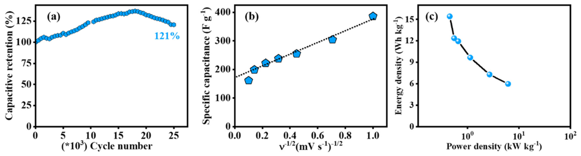
| HRFLG | Hydroxyl-rich FLG | 2 M | 320 | 1 A g | 6.1 | 15.4 | 121% (25,000 cycles at 100 mV s) | [66] |
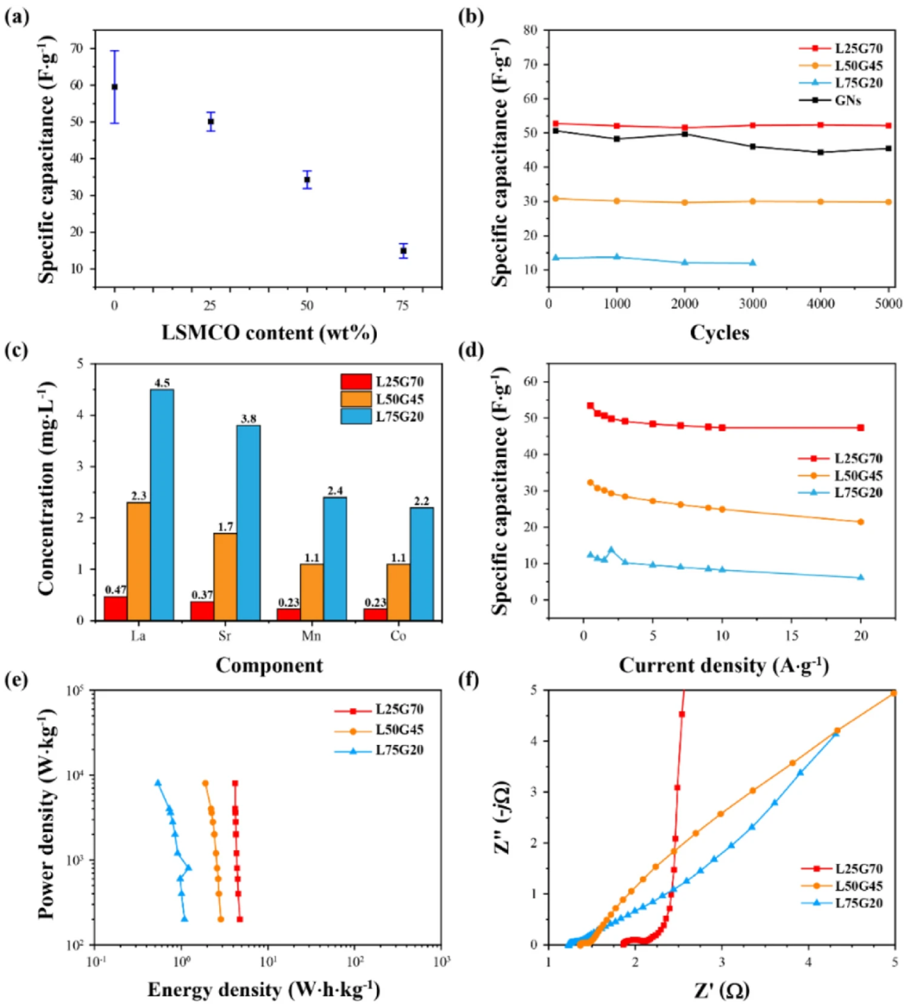
| LSMCO-GNP | LSMCO perovskite ‡/ GNP composite | 1 M | 50.11 | 5 mV s | - | 4.74–4.20 | - | [65] |
Publisher’s Note: MDPI stays neutral with regard to jurisdictional claims in published maps and institutional affiliations. |
© 2022 by the authors. Licensee MDPI, Basel, Switzerland. This article is an open access article distributed under the terms and conditions of the Creative Commons Attribution (CC BY) license (https://creativecommons.org/licenses/by/4.0/).
Share and Cite
Worsley, E.A.; Margadonna, S.; Bertoncello, P. Application of Graphene Nanoplatelets in Supercapacitor Devices: A Review of Recent Developments. Nanomaterials 2022, 12, 3600. https://doi.org/10.3390/nano12203600
Worsley EA, Margadonna S, Bertoncello P. Application of Graphene Nanoplatelets in Supercapacitor Devices: A Review of Recent Developments. Nanomaterials. 2022; 12(20):3600. https://doi.org/10.3390/nano12203600
Chicago/Turabian StyleWorsley, Eleri Anne, Serena Margadonna, and Paolo Bertoncello. 2022. "Application of Graphene Nanoplatelets in Supercapacitor Devices: A Review of Recent Developments" Nanomaterials 12, no. 20: 3600. https://doi.org/10.3390/nano12203600
APA StyleWorsley, E. A., Margadonna, S., & Bertoncello, P. (2022). Application of Graphene Nanoplatelets in Supercapacitor Devices: A Review of Recent Developments. Nanomaterials, 12(20), 3600. https://doi.org/10.3390/nano12203600