


Featured Application
This paper details the simulated and experimental performance of a newly developed electric generator intended for use in small wind turbines.
Abstract
This paper investigates the electromagnetic performance of an outer-rotor spoke-type permanent magnet synchronous generator intended for small wind turbine applications below 5 kW. The study focuses on the influence of structural ferromagnetic components on magnetic flux distribution and overall machine performance. The generator was initially designed and optimized using 2D finite element analysis, followed by a comprehensive 3D model to account for axial flux leakage and structural details; particular attention was given to the fastening screws used. Experimental validation on a dedicated laboratory test bench confirms the accuracy of the 3D model, mainly at lower wind speeds. The results highlight the necessity of including structural components in three-dimensional electromagnetic modeling for accurate performance prediction of flux-concentrating wind turbine generators.
1. Introduction
Small-scale renewable energy systems are increasingly used for residential, rural, and off-grid applications. In recent years, photovoltaic systems have become very popular due to their simple installation, modular structure, and continuously decreasing costs. However, small wind turbines, especially those with rated power below 5 kW, still represent a viable solution in locations where wind resources are abundant and solar energy alone cannot ensure continuous power generation [1,2,3].
One important advantage of small wind turbines compared to photovoltaic systems is their ability to generate energy independently of solar radiation. Wind energy production can occur during nighttime and during periods of low solar irradiance, such as winter or cloudy days. Several studies indicate that, under suitable wind conditions, small wind turbines can achieve higher annual energy production and better capacity factors than photovoltaic systems with the same installed power [3,4,5]. For this reason, small wind turbines are often considered a complementary or alternative solution to photovoltaic systems in decentralized energy systems.
Small wind turbines are commonly classified according to rotor orientation into vertical-axis and horizontal-axis configurations. Vertical-axis wind turbines offer simple mechanical layouts and insensitivity to wind direction, but their aerodynamic efficiency is generally lower. Horizontal-axis wind turbines are more widely used due to their higher efficiency and better performance at moderate wind speeds [6]. Among these, three-bladed horizontal-axis wind turbines are the most common configuration, as they provide a good balance between energy capture, mechanical stability, noise levels, and structural loading [7].
The electrical generator plays a key role in the overall performance of a small wind turbine. Permanent magnet synchronous generators are widely adopted in small-scale wind applications because of their high efficiency, compact size, and reduced maintenance requirements [8]. In addition, permanent magnet machines allow direct-drive operation, eliminating the need for gearboxes and increasing system reliability.
Outer-rotor permanent magnet synchronous generators are particularly suitable for small wind turbines, as they can deliver high torque at low rotational speeds and can be mechanically integrated directly with the turbine rotor. Among different rotor topologies, spoke-type permanent magnet arrangements offer improved magnetic flux concentration and higher torque density compared to surface-mounted magnet designs [9,10,11]. These characteristics make spoke-type outer-rotor generators well suited for low-speed wind energy applications.
In this work, an outer-rotor spoke-type permanent magnet synchronous generator is designed and analyzed for integration with a horizontal-axis, three-bladed wind turbine rated below 5 kW. The proposed generator aims to achieve high efficiency, compact dimensions, and reliable operation under typical operating conditions encountered in small wind energy systems.
Although outer-rotor spoke-type permanent magnet generators have sometimes been studied for small wind turbine applications, most existing studies mainly focus on the optimization of the active magnetic circuit, such as rotor geometry, magnet arrangement, and winding configurations. The influence of structural components that are not intentionally part of the magnetic circuit is generally neglected in electromagnetic models.
The novelty of this study lies in the investigation of the electromagnetic impact of structural ferromagnetic elements in a flux-concentrating outer-rotor permanent magnet generator. In particular, the influence of rotor fastening screws on magnetic flux distribution, induced voltage, torque, and loss components is analyzed using both two-dimensional and three-dimensional finite-element models. The numerical results are further validated experimentally using a laboratory prototype.
2. Materials and Methods
2.1. Application Constraints Imposed by the Wind Turbine
The generator considered in this work is intended for integration into a small-scale horizontal-axis wind turbine with three blades and a rated power below 5 kW. Wind turbines in this power range usually operate at low rotational speeds and are exposed to variable aerodynamic torque due to wind speed fluctuations. Therefore, the generator must be capable of delivering high electromagnetic torque at low speeds, while maintaining stable and efficient operation over a wide operating range.
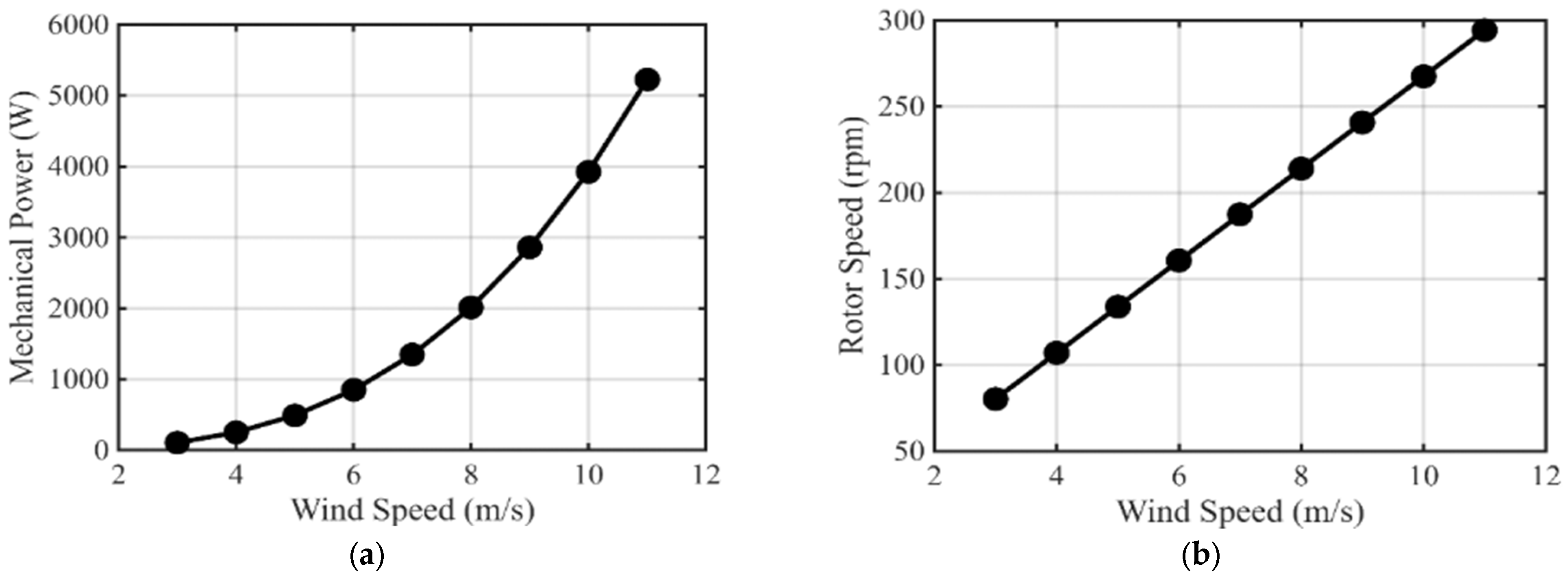
The operating characteristic of the wind turbine, expressed as the relationship between wind speed, generator rotational speed, and output power, is presented in Figure 1. As shown by this characteristic, the generator is required to operate over a broad speed range, starting from low wind velocities and extending to higher wind conditions where both rotational speed and power increase significantly. This behavior imposes strict constraints on torque capability, voltage generation, and efficiency across varying load conditions.
Figure 1.
Wind turbine characteristics: (a) mechanical power as a function of wind speed; (b) generator rotational speed as a function of wind speed.
For small wind turbines, direct-drive operation is often preferred to avoid mechanical gearboxes. Removing the gearbox reduces mechanical losses, maintenance needs, and potential points of failure, while improving overall system reliability and acoustic performance. However, direct-drive operation places strict requirements on the generator, particularly regarding torque density, magnetic loading, and thermal behavior.
In addition, the generator must tolerate mechanical stress caused by start-up transients, turbulent wind conditions, and cyclic loading during long-term operation. These constraints directly influence the choice of generator topology and rotor configuration, making robust electromagnetic and mechanical design essential for small wind turbine applications.
In Figure 1, the performance of the wind turbine is presented, considering this application. These characteristics are used as a reference for the development and testing of the electrical generator.
2.2. Selection of an Outer-Rotor Permanent Magnet Generator
Given the low-speed operation of the considered wind turbine, an outer-rotor permanent magnet synchronous generator is a suitable solution. In outer-rotor machines, the rotor is positioned around the stator, resulting in a larger effective air-gap radius compared to inner-rotor configurations. This geometric feature enables higher torque production without increasing current density or magnetic loading, which is advantageous for low-speed applications [12].
From a mechanical integration perspective, the outer-rotor configuration allows direct coupling between the generator rotor and the turbine hub. This simplifies the mechanical structure and improves torque transmission. Additionally, the increased rotor inertia may contribute to smoother rotational behavior under fluctuating wind conditions [13].
Electromagnetically, outer-rotor permanent magnet machines can achieve favorable flux distribution and reduced end-winding length, which may lead to lower copper losses and improved efficiency. These characteristics make outer-rotor generators well suited for direct-drive small wind energy systems [14].
Among the available permanent magnet rotor topologies, a spoke-type configuration has been selected for the proposed generator. In this topology, permanent magnets are embedded radially within the rotor core, allowing magnetic flux to be concentrated in the air gap. Compared to surface-mounted magnet designs, spoke-type rotors can achieve higher air-gap flux density and increased torque density for a similar magnet volume [15,16].
The flux-concentrating behavior of spoke-type permanent magnet machines is particularly beneficial for low-speed, high-torque applications, such as direct-drive wind turbine generators. Previous studies have shown that spoke-type machines can provide improved torque capability and overload performance when compared to surface-mounted magnet machines operating under similar conditions [17].
Embedding the magnets within the rotor also improves mechanical robustness by protecting the magnets from centrifugal forces and external mechanical damage. This aspect is important for wind turbine generators, which are subjected to cyclic mechanical loads and long-term operation. Furthermore, the spoke-type configuration offers design flexibility, allowing optimization of magnet placement and rotor geometry to reduce cogging torque and torque ripple [18].
2.3. Generator Structure and Finite Element Model
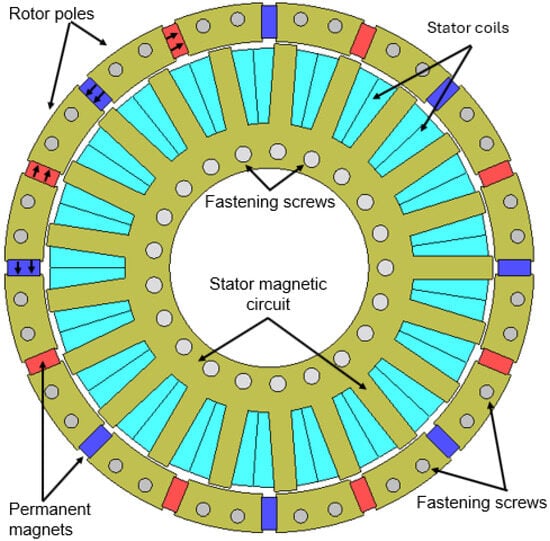
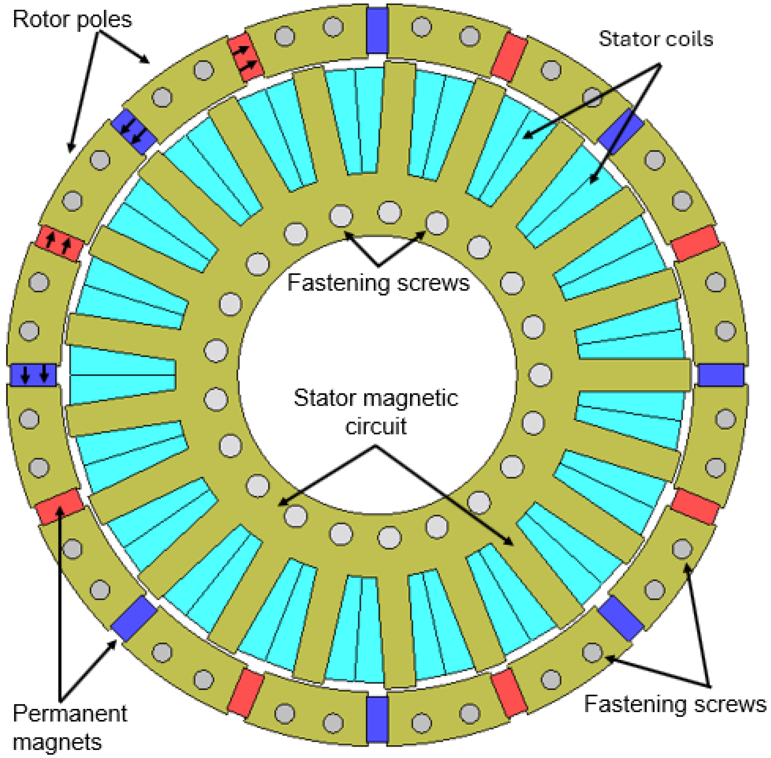
The proposed generator consists of a laminated stator equipped with concentrated windings and an outer rotor containing radially embedded permanent magnets arranged in a spoke-type configuration. The main active components of the machine include the stator core, stator windings, rotor core, permanent magnets, and the air gap between the stator and rotor (Figure 2).
Figure 2.
Active components of the outer-rotor PM generator.
A concentrated winding layout was selected to simplify the stator’s winding structure and reduce end-winding length, which contributes to lower copper losses and improved manufacturability. This winding configuration is well suited for low-speed permanent magnet machines requiring high torque density and compact construction. To obtain a low output voltage level, each stator coil is wound using parallel conductors consisting of two wires with a diameter of 2 mm. This approach enables higher current capability while maintaining acceptable current density and limiting the phase voltage.
The use of parallel conductors increases the effective copper cross-section and contributes to improved thermal performance by reducing resistive losses. Such a low-voltage, high-current configuration is compatible with power electronic converters typically employed in small wind energy systems and facilitates integration with DC-link or battery-based energy storage systems.
The electromagnetic behavior of the proposed generator was initially investigated using a two-dimensional finite element model developed in JMAG Designer ver. 24.2 (Figure 2). The 2D model was used to analyze key performance indicators such as air-gap flux density distribution, electromagnetic torque, torque ripple, and loss components under different operating conditions. The geometric parameters of the stator, rotor, magnets, and windings were defined based on the application constraints discussed in the previous subsections and refined through iterative electromagnetic simulations.
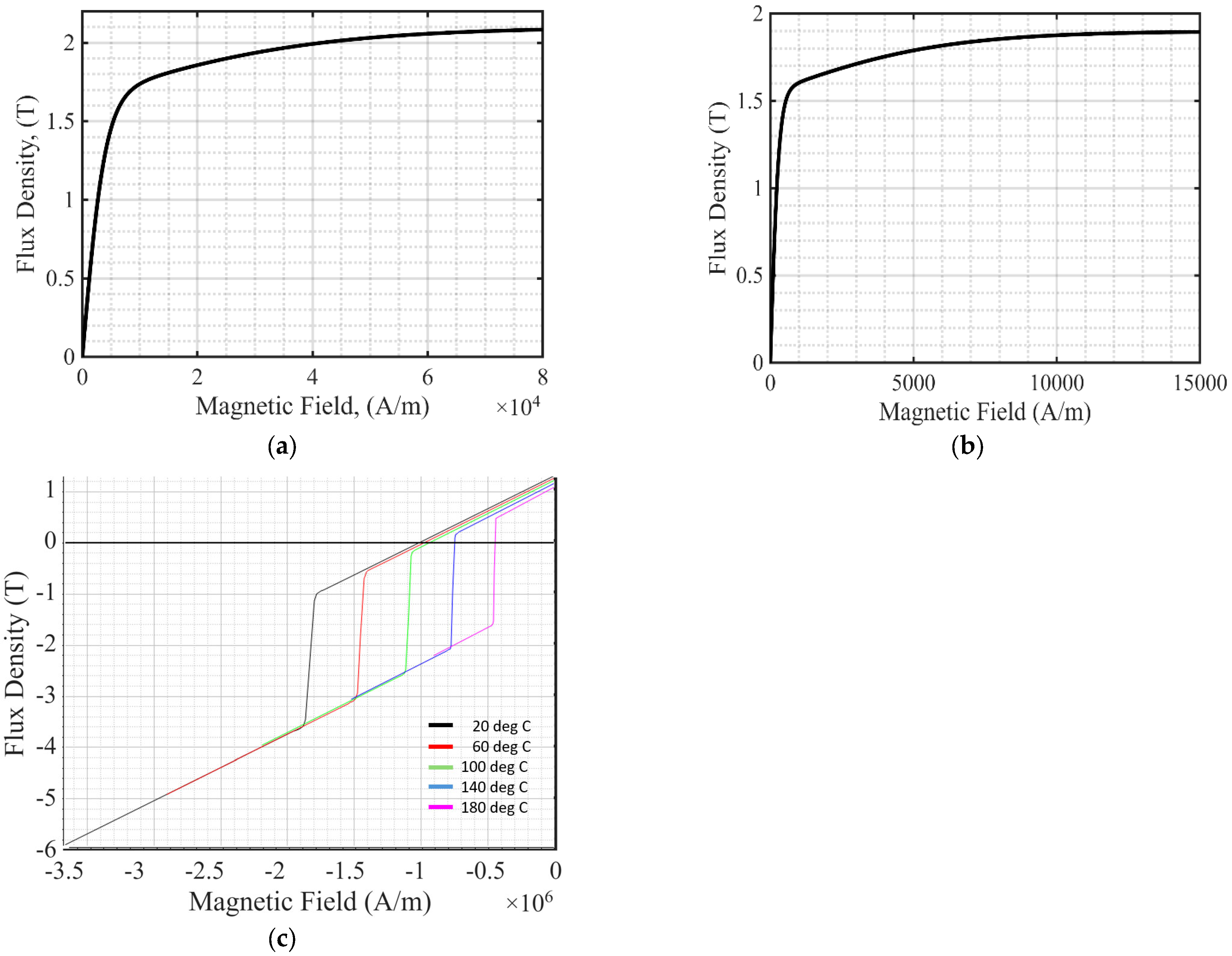
A detailed illustration of the generator active components obtained from the finite element model, along with a table summarizing the main geometric dimensions and winding parameters of the prototype, is presented in Figure 2 and Table 1. In Appendix A, Figure A1, the B-H characteristics of some generator’s components are shown.
Table 1.
Main geometric dimensions and winding parameters of the prototype.
In addition to electromagnetic performance, the mechanical structure of the generator was designed with emphasis on simplicity, compactness, and low-cost manufacturing using standard workshop equipment. The rotor assembly consists of laminated steel poles mechanically fixed between two aluminum flanges, forming a modular structure.
The generator is axially closed using non-magnetic polymer components manufactured by 3D printing. These parts provide mechanical positioning and structural support while avoiding additional magnetic paths.
Standard fastening screws are used to ensure mechanical rigidity under cyclic loading conditions typical for small wind turbine operation. The overall design objective was to balance electromagnetic performance with manufacturability and cost efficiency. As discussed in Section 3, certain structural components may introduce unintended electromagnetic effects in flux-concentrating topologies.
During the preparation of this manuscript, ChatGPT-5.2 was used to assist in drafting parts of the abstract and conclusions.
3. Results
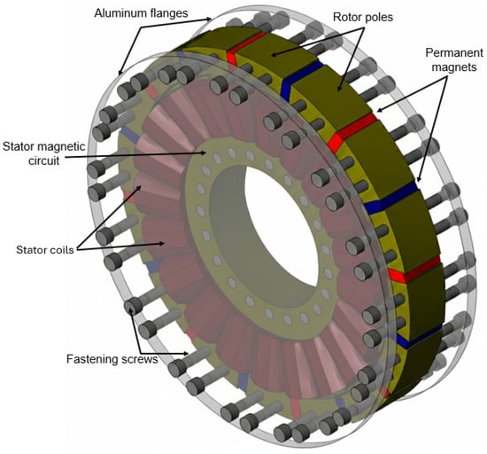
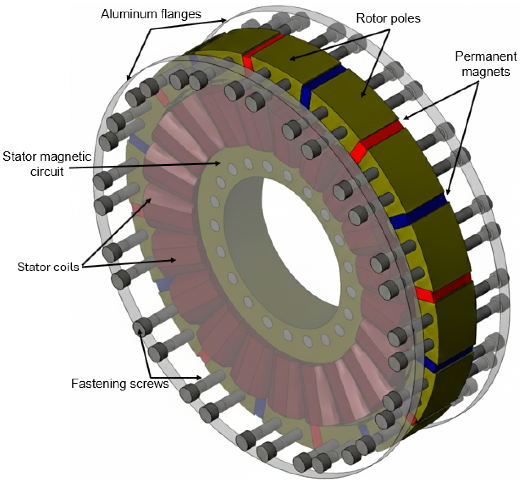
In addition to the two-dimensional analysis, a three-dimensional finite element model of the generator was also developed (Figure 3). The purpose of the 3D model is to further investigate effects that cannot be fully captured in 2D simulations, including end-winding influence, axial flux leakage, and three-dimensional flux distribution.
Figure 3.
Three-dimensional model of the outer-rotor PM generator.
3.1. No-Load Performance and Influence of Structural Ferromagnetic Components
The initial evaluation of the generator performance was carried out under no-load conditions using the two-dimensional finite element model described in Section 2.3. In the preliminary electromagnetic model, structural components such as fastening screws and mechanical fixtures were not included, as they were considered non-active parts with negligible influence on the main magnetic flux path. However, during the experimental validation stage, differences between simulated and measured no-load quantities were observed. This led to a supplementary investigation into the influence of structural ferromagnetic components, particularly the two fastening screws used to fix each rotor pole to the aluminum flanges. The 3D finite element model was discretized using a refined mesh in regions where high magnetic field gradients are expected. In the air-gap region, a maximum element size of 1 mm was used to accurately capture the magnetic flux distribution between the stator and rotor. In the ferromagnetic regions of the stator and rotor laminations, a maximum element size of 3 mm was employed. This meshing strategy ensures sufficient numerical accuracy while maintaining a reasonable computational cost.
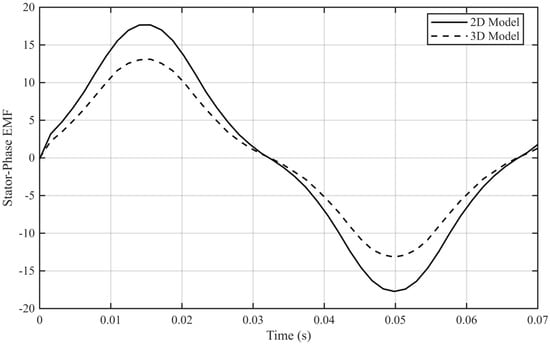
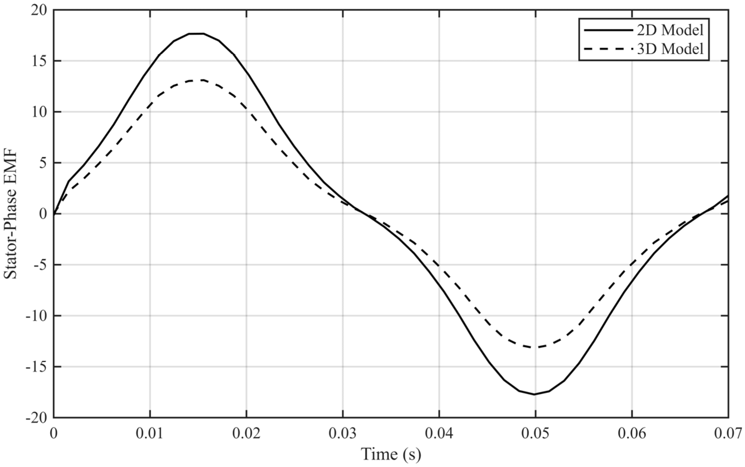
Figure 4 shows the no-load phase back-EMF waveform obtained from the 2D and 3D finite element models. The 2D simulation predicts a peak amplitude of 18 V, whereas the 3D model yields 13.5 V, corresponding to a reduction of approximately 25%. This discrepancy is mainly attributed to the inherent limitations of the 2D approach, which neglects axial flux leakage, end-winding effects, and the finite stack length of the machine. In contrast, the 3D model accounts for these three-dimensional effects, leading to a lower and more realistic estimation of the induced voltage.
Figure 4.
No-load phase back-EMF waveform obtained from the 2D and 3D finite element models at 107 rev/min.
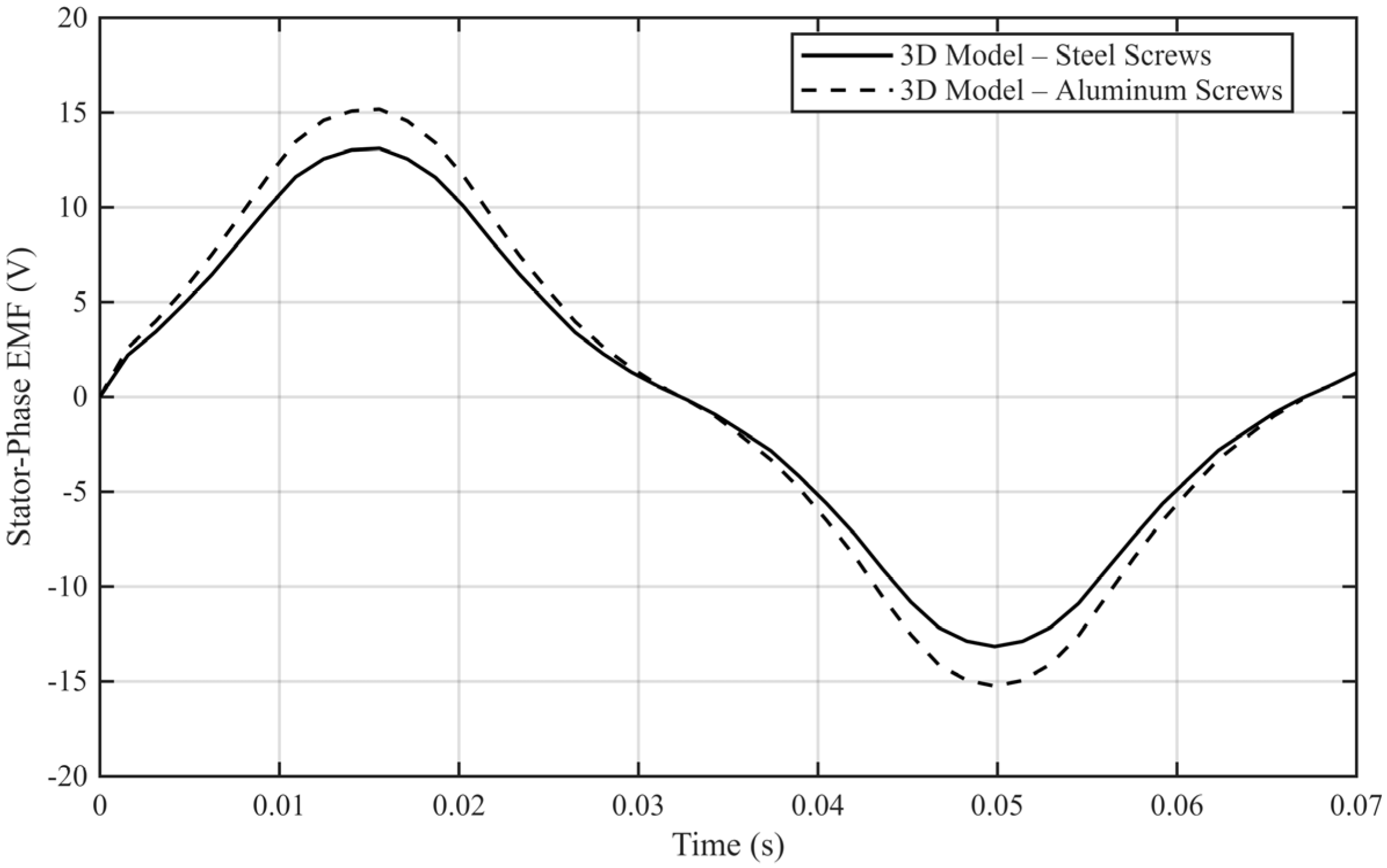
Figure 5 presents a 3D comparison of the no-load phase voltage for two structural configurations: aluminum fastening screws (non-magnetic) and steel screws. When steel screws are considered, the peak voltage decreases from 15.1 V to 13.5 V, corresponding to a reduction of approximately 10.6%. This result confirms that ferromagnetic structural elements introduce unintended magnetic flux paths. In the spoke-type rotor configuration, the steel screws facilitate localized flux closure between adjacent screws, reducing the effective air-gap flux and consequently decreasing not only the induced phase voltage, but also the nominal power developed by the machine.
Figure 5.
No-load phase back-EMF waveform: 3D comparison of the no-load phase voltage for two structural configurations: aluminum fastening screws (non-magnetic) and steel screws at 107 rev/min.
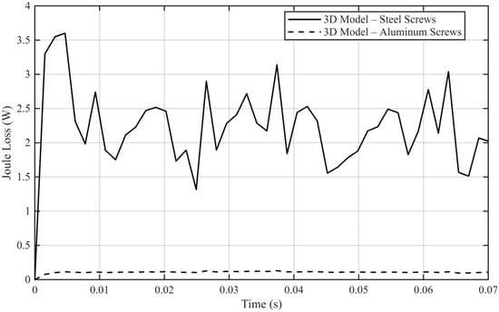
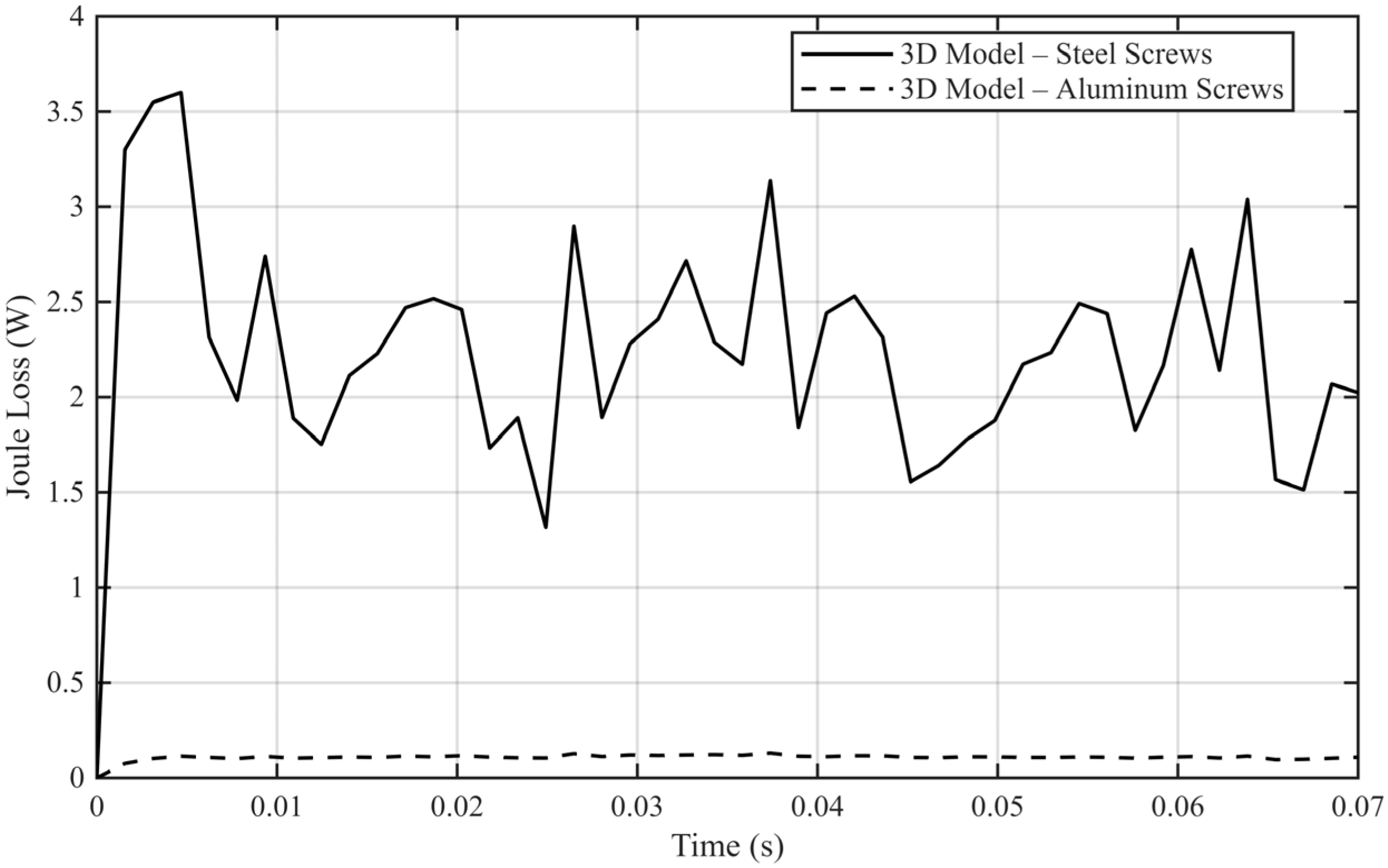
Figure 6 presents the total Joule losses produced by eddy currents under no-load conditions, as obtained from the 3D finite element model for the two fastening configurations. These losses are distributed within the permanent magnets and, in the case of the ferromagnetic configuration, also within the steel screws mounted on the rotor.
Figure 6.
Total Joule losses produced by eddy currents under no-load conditions.
In the aluminum-screw configuration, the computed loss component is mainly associated with eddy currents induced in the permanent magnets, since the fastening elements do not provide a magnetic path. When steel screws are introduced, additional eddy-current losses appear in these ferromagnetic components due to the local magnetic flux concentration and the formation of unintended flux paths between adjacent screws.
Therefore, the difference between the two curves shown in Figure 6 corresponds to the eddy-current losses generated in the steel screws at the rotor level. The approximately 2.35 W increase observed for the steel configuration is directly attributed to these additional rotor losses.
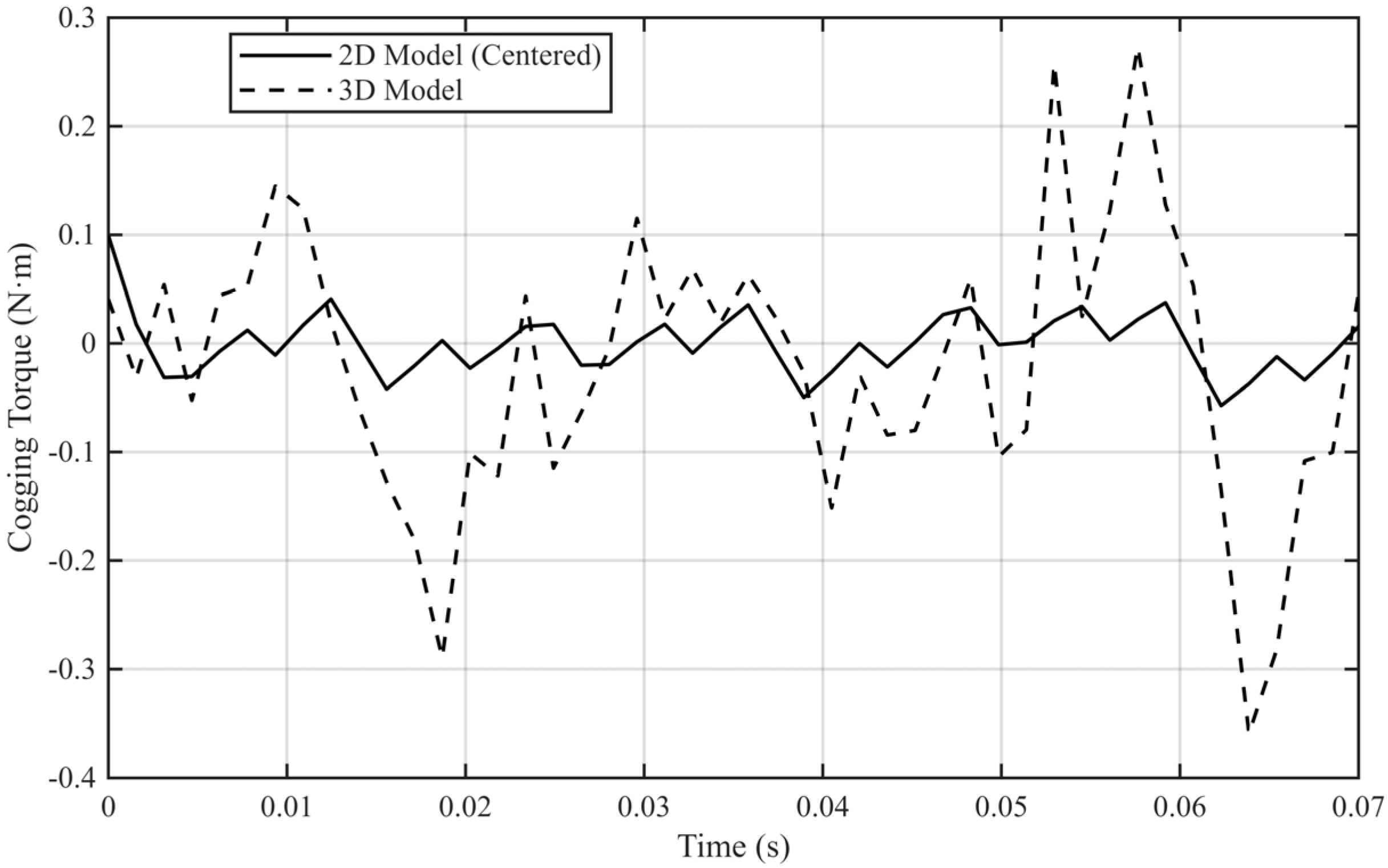
Figure 7 shows the electromagnetic torque under no-load conditions obtained from both 2D and 3D models, highlighting the cogging torque component. The cogging torque predicted by the 2D model is lower than the value obtained in 3D. This behavior is expected, since 2D simulations are based on a simplified representation of the machine geometry, while the 3D model accounts for the complete spatial configuration of the generator. For compact machines with relatively short axial length and flux-concentrating topologies, 2D models may significantly overestimate the induced voltage, making 3D validation essential.
Figure 7.
Cogging torque component predicted by the 2D and 3D models.
3.2. Load Performance and Influence of Structural Ferromagnetic Components
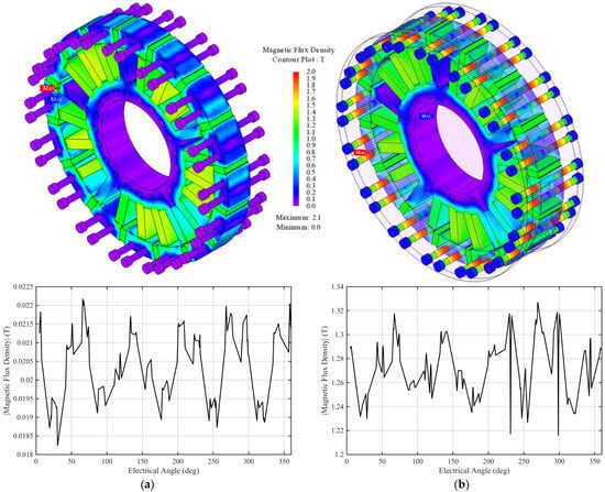
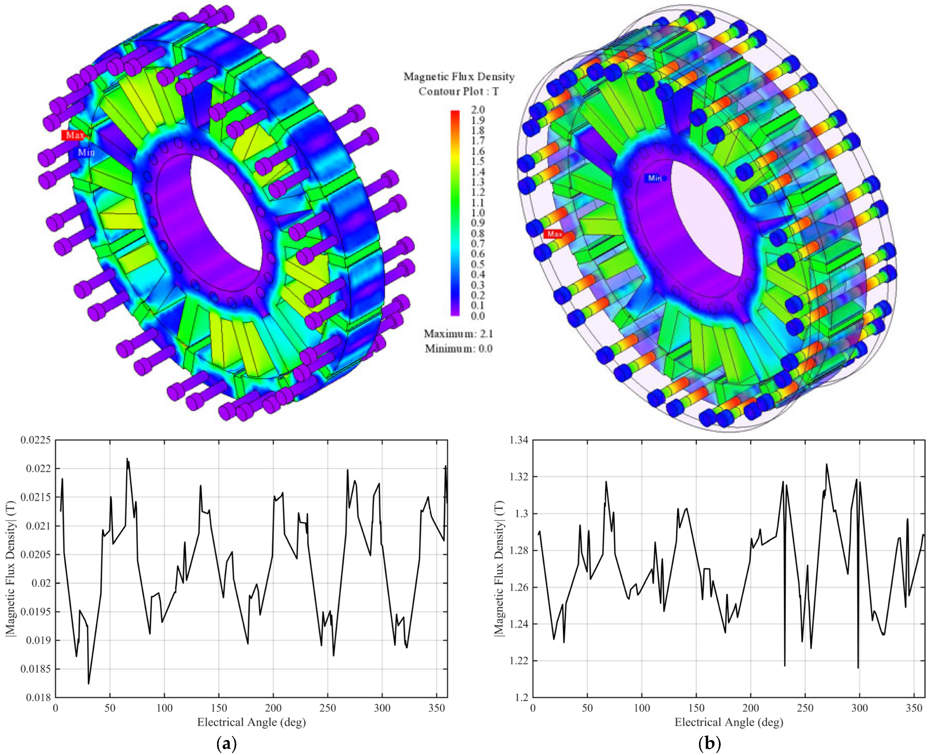
Figure 8 presents the magnetic flux density distribution under load conditions for two configurations: (a) a reference model including non-magnetic fastening screws, and (b) a modified model including ferromagnetic fastening screws. To provide a quantitative comparison of the magnetic field distribution, an additional radial section of the magnetic flux density was extracted from the 3D model. The section was defined at a radius corresponding to the midline of the fastening screws and located in the median plane of the aluminum flange. This radial path intersects the center of the two screws fixing each rotor pole. The resulting flux density profile is also presented in Figure 8. The comparison clearly highlights the differences between the ferromagnetic and non-magnetic fastening configurations. In the case of ferromagnetic screws, localized peaks of magnetic flux density appear in the region between the two screws, confirming the formation of an unintended magnetic bridge. In contrast, the non-magnetic fastening solution preserves the intended spoke-type flux-concentrating path toward the air gap, without significant flux distortion in the flange region.
Figure 8.
Magnetic flux density distribution for (a) a reference model including non-magnetic fastening screws (stainless steel or aluminum) and (b) a modified model including ferromagnetic fastening screws.
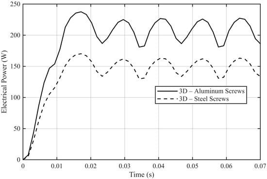
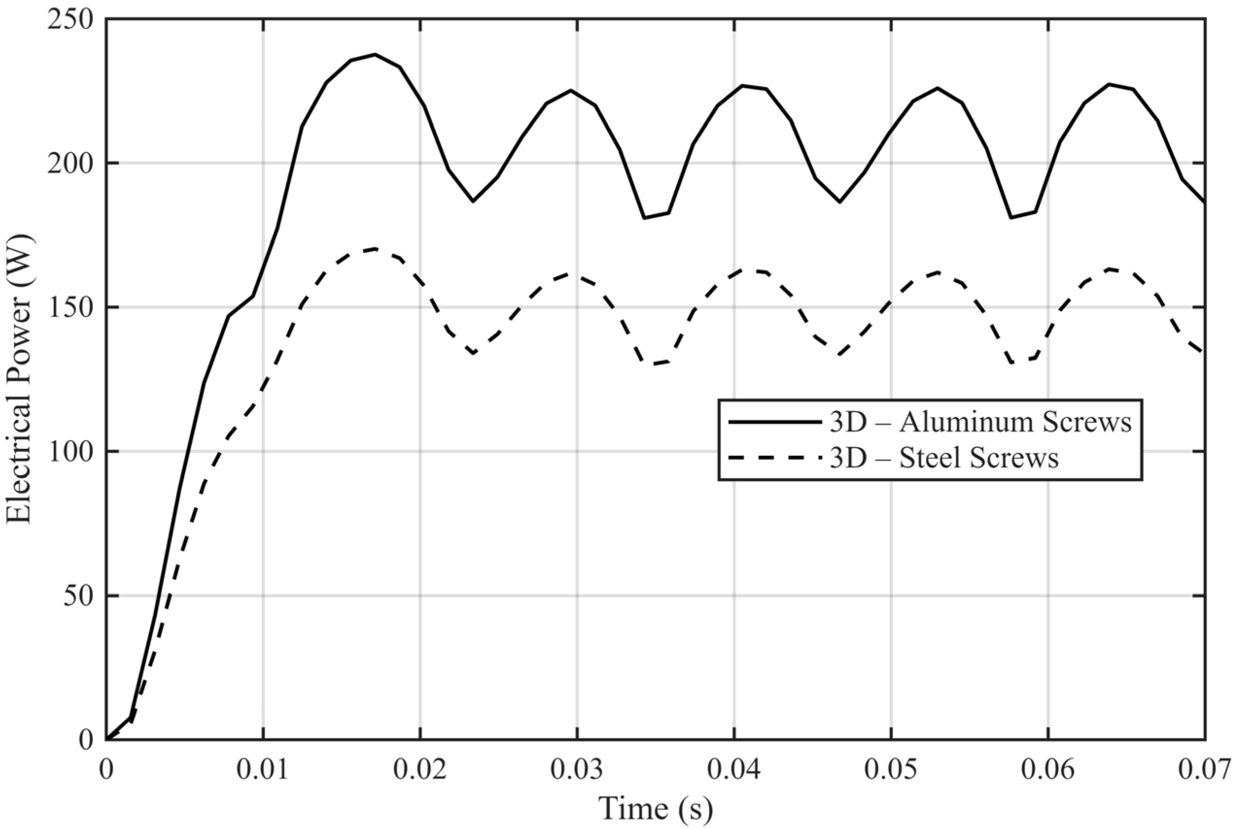
The following simulations were performed using a three-phase diode bridge rectifier and a resistive load. The electrical output power obtained in the two configurations (Figure 9) highlights a clear performance degradation when steel screws are used. The presence of ferromagnetic fastening elements introduces additional localized flux paths within the rotor structure. Therefore, the induced phase voltage decreases, which directly affects the generated electrical power under identical operating conditions.
Figure 9.
Electrical output power comparison obtained from the 3D model for aluminum and steel fastening screws.
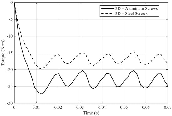
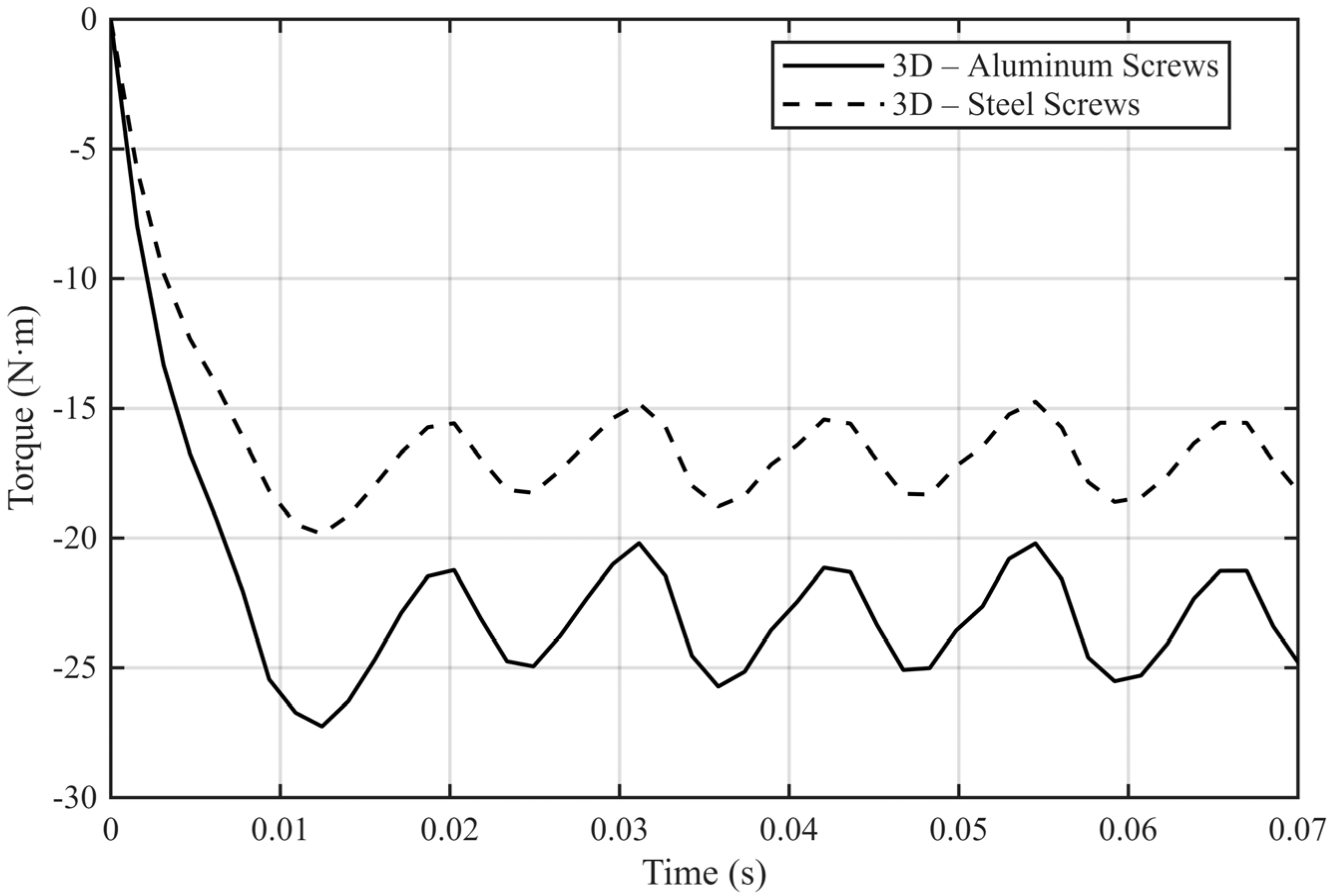
A similar trend is observed in the electromagnetic torque results at 107 rev/min under the same electrical load condition (Figure 10). For the configuration employing aluminum screws, the torque profile exhibits higher average values and improved stability. When steel screws are introduced, the average torque decreases due to the reduction in effective air-gap flux density.
Figure 10.
Electromagnetic torque comparison obtained from the 3D model for aluminum and steel fastening screws at 107 rev/min under the same load value.
Overall, the comparative results clearly demonstrate that structural ferromagnetic components, even when not directly part of the main magnetic circuit, can significantly influence the electromagnetic performance of flux-concentrating machines. These results indicate that all structural elements should be included in the three-dimensional electromagnetic model during the design phase. Neglecting such components in simplified 2D simulations may lead to overestimation of generator performance and inaccurate prediction of operating characteristics.
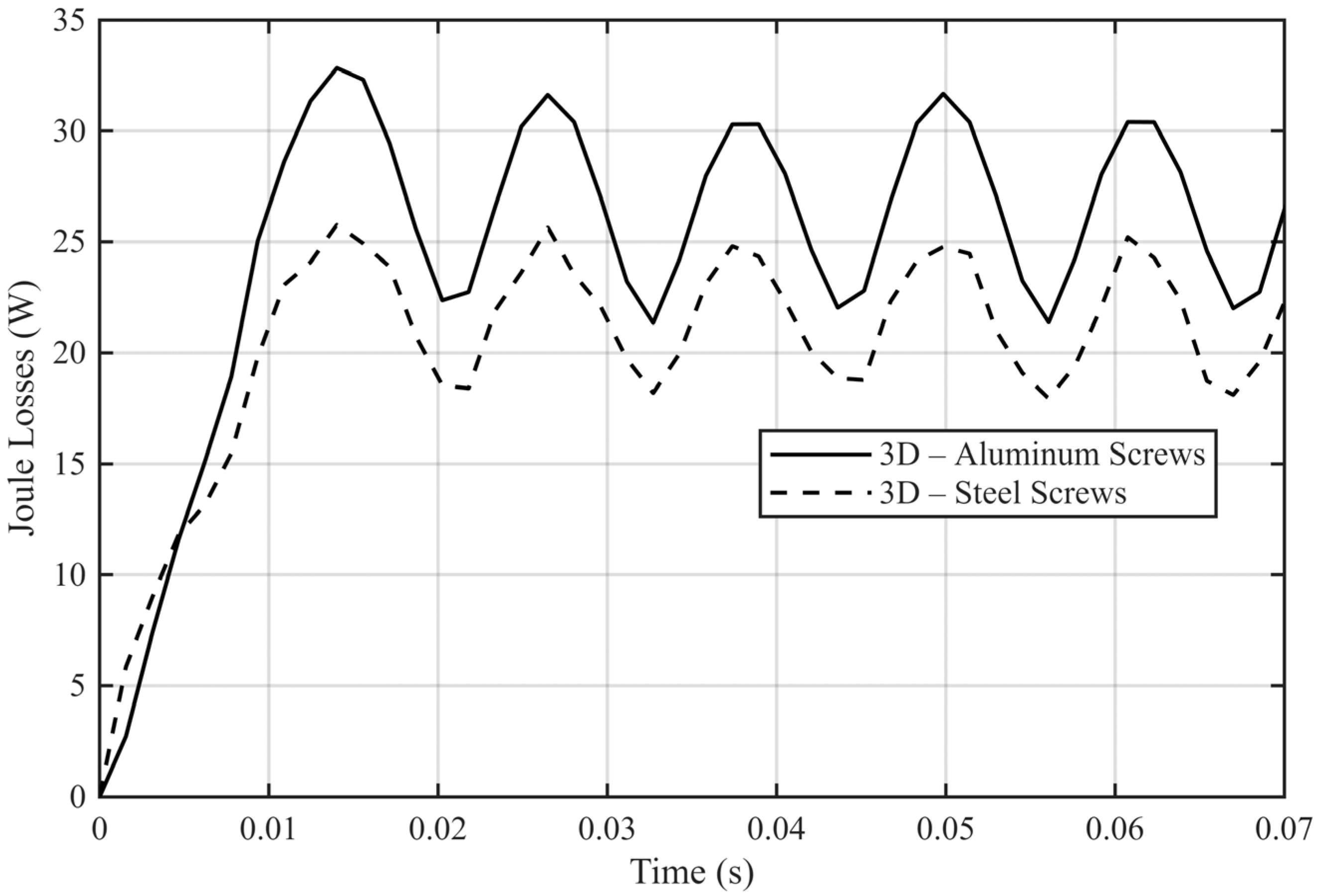
A particular aspect observed in the comparative analysis concerns the Joule losses (coils—direct Joule losses, PMs—eddy current losses, screws—eddy current losses) computed for the two fastening configurations in Figure 11. The aluminum-screw configuration exhibits slightly higher stator copper losses compared to the steel-screw case. This behavior is not associated with inferior performance; rather, it is a direct consequence of improved magnetic flux utilization. In the non-magnetic fastening configuration, the magnetic flux follows the intended spoke-type flux-concentrating path.
Figure 11.
Joule loss comparison obtained from the 3D model for aluminum and steel fastening screws.
The absence of ferromagnetic bridges ensures proper air-gap flux linkage with the stator magnetic circuit, leading to higher induced voltage and increased electromagnetic torque. Under load, this results in higher flux linkage and consequently higher copper (Joule) losses. When steel screws are used, part of the magnetic flux is diverted through parasitic rotor paths, reducing the effective air-gap flux and lowering both induced voltage and torque. The reduced electromagnetic loading explains the slightly lower Joule losses observed in this case. Thus, the higher copper losses in the aluminum-screw configuration are directly associated with improved flux linkage and enhanced electromagnetic performance.
3.3. Experimental Results
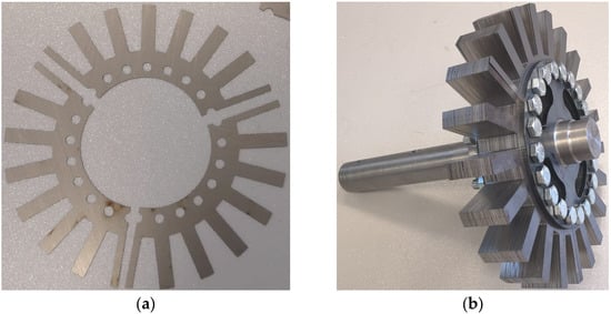
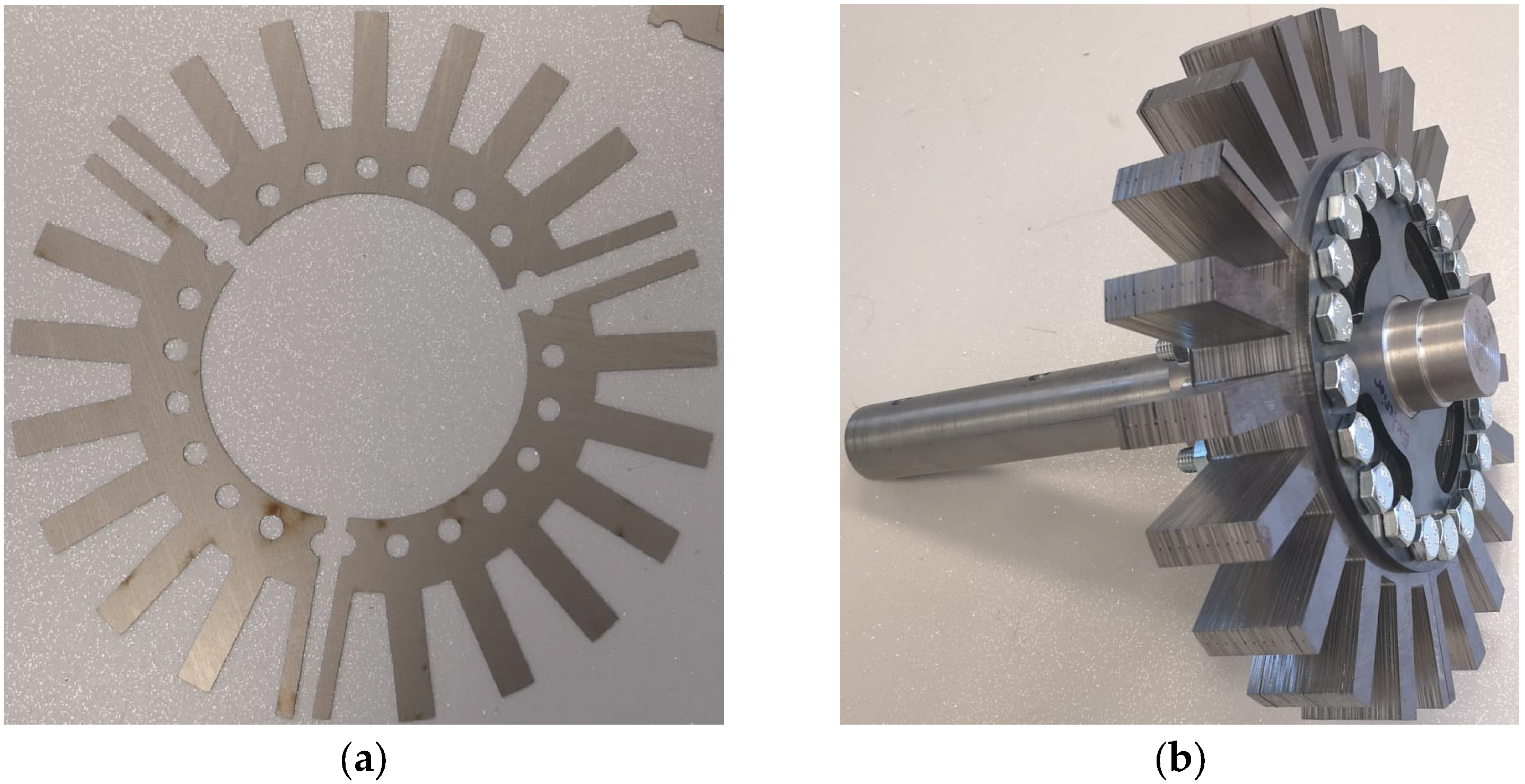
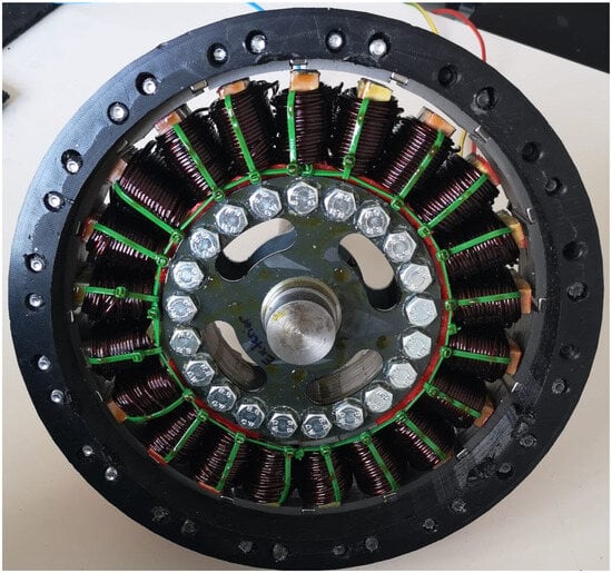
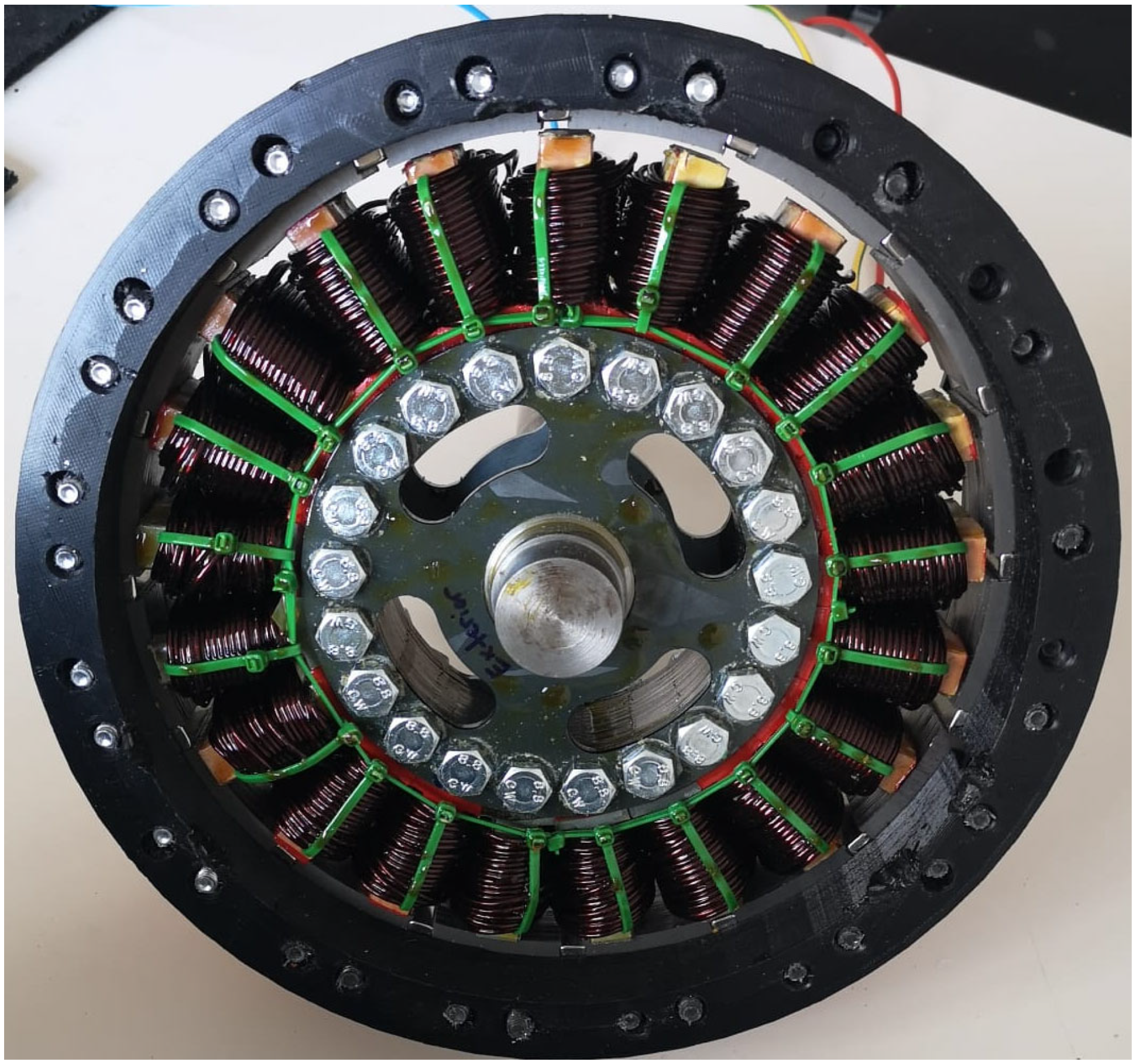
The stator of the proposed generator was manufactured using laminated electrical steel sheets assembled into a rigid core structure. The steel sheets were stacked to the required active length of 40 mm and mechanically compressed to ensure structural stability. The concentrated winding configuration was implemented using parallel conductors (two wires of 2 mm diameter per coil), allowing a low-voltage, high-current design suitable for small-scale wind energy applications. Each slot accommodates pre-formed concentrated coils, which can be individually assembled. Figure 12 presents the stator assembly of the prototype. The laminated core, concentrated windings, and slot arrangement are visible in Figure 13, highlighting the compact geometry and short end-winding length achieved through the selected topology.
Figure 12.
Stator prototype magnetic core—(a) Modular stator lamination segments and (b) assembled laminated core stack secured with fastening screws.
Figure 13.
Internal structure of the electric generator.
The rotor assembly follows a modular concept, in which each laminated steel pole, containing radially embedded permanent magnets, is mechanically fixed between two aluminum flanges. This configuration ensures mechanical rigidity while maintaining low overall weight. The axial closing of the machine is achieved using non-magnetic polymer components manufactured by 3D printing. These elements provide mechanical alignment and structural support without introducing additional magnetic flux paths.
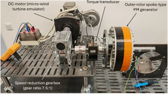
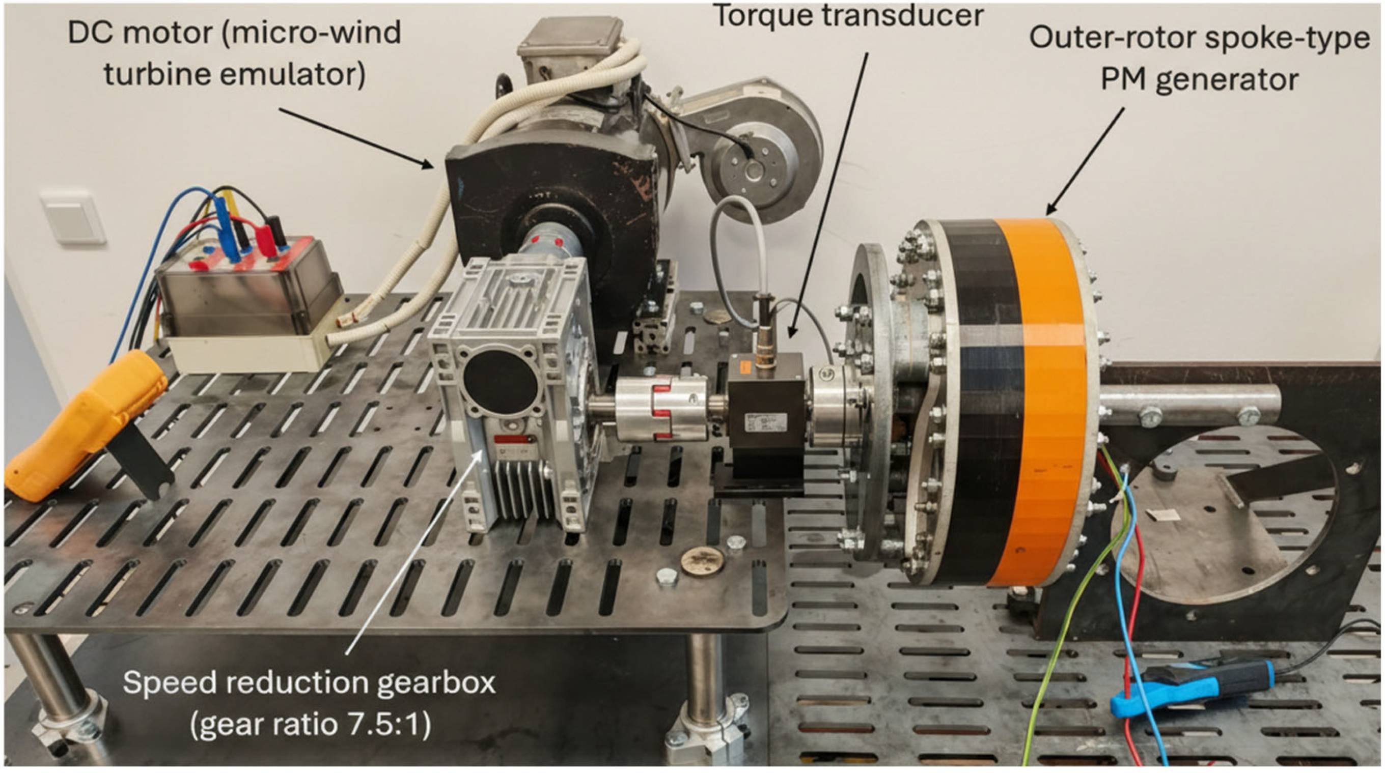
The experimental test bench used for validation is presented in Figure 14. The setup consists of a 7.7 kW, 2700 rev/min DC motor used as the prime mover (micro-wind turbine emulator), the outer-rotor spoke-type permanent magnet generator, a speed reduction gearbox with a transmission ratio of 7.5:1, an adjustable DC power supply, a resistive load bank, a torque and speed transducer and a dSPACE 1103 real-time platform to recover and measure signals. This configuration allows the available torque at the generator shaft to exceed 50 Nm, ensuring safe and stable operation during testing. As in simulations, a three-phase diode bridge rectifier was used to convert a.c. power to d.c. power, with the load consisting of a variable resistor.
Figure 14.
Experimental laboratory setup for testing the prototype.
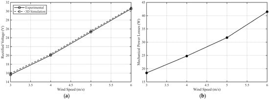
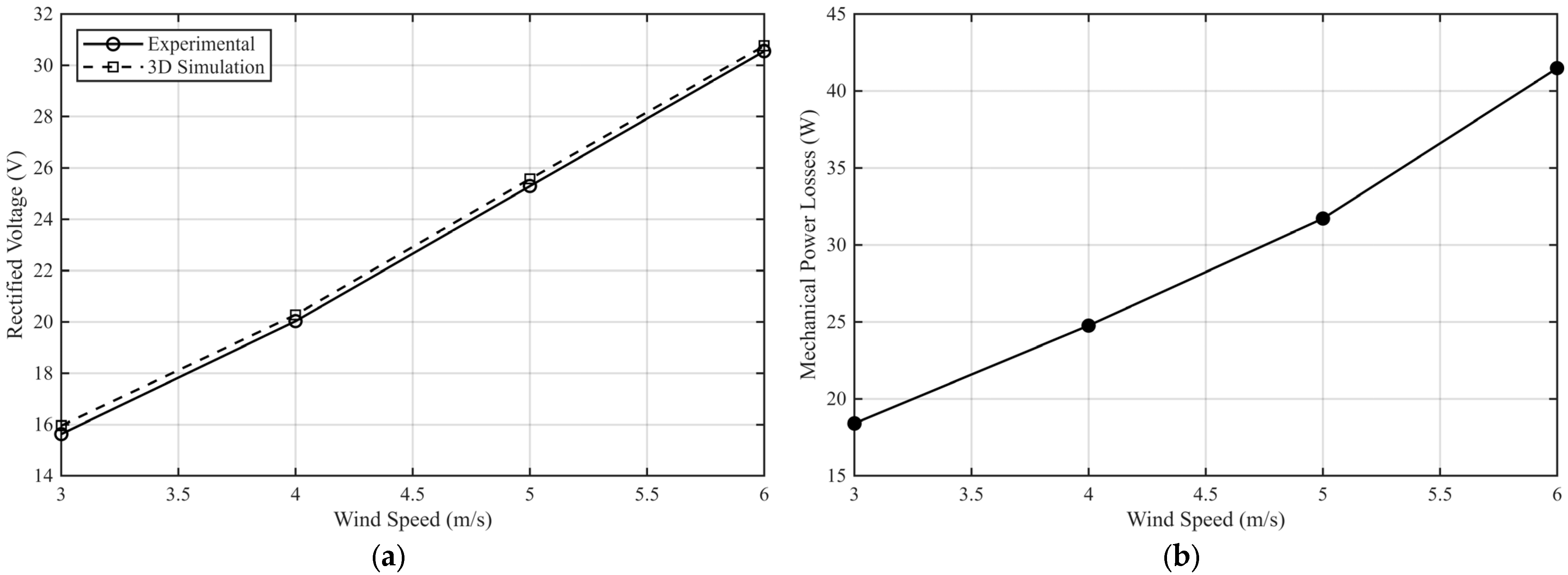
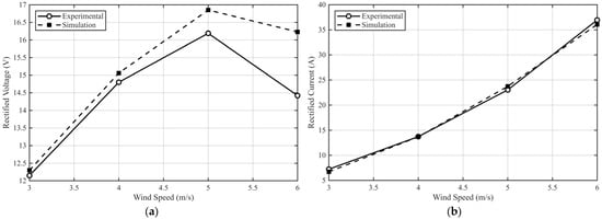
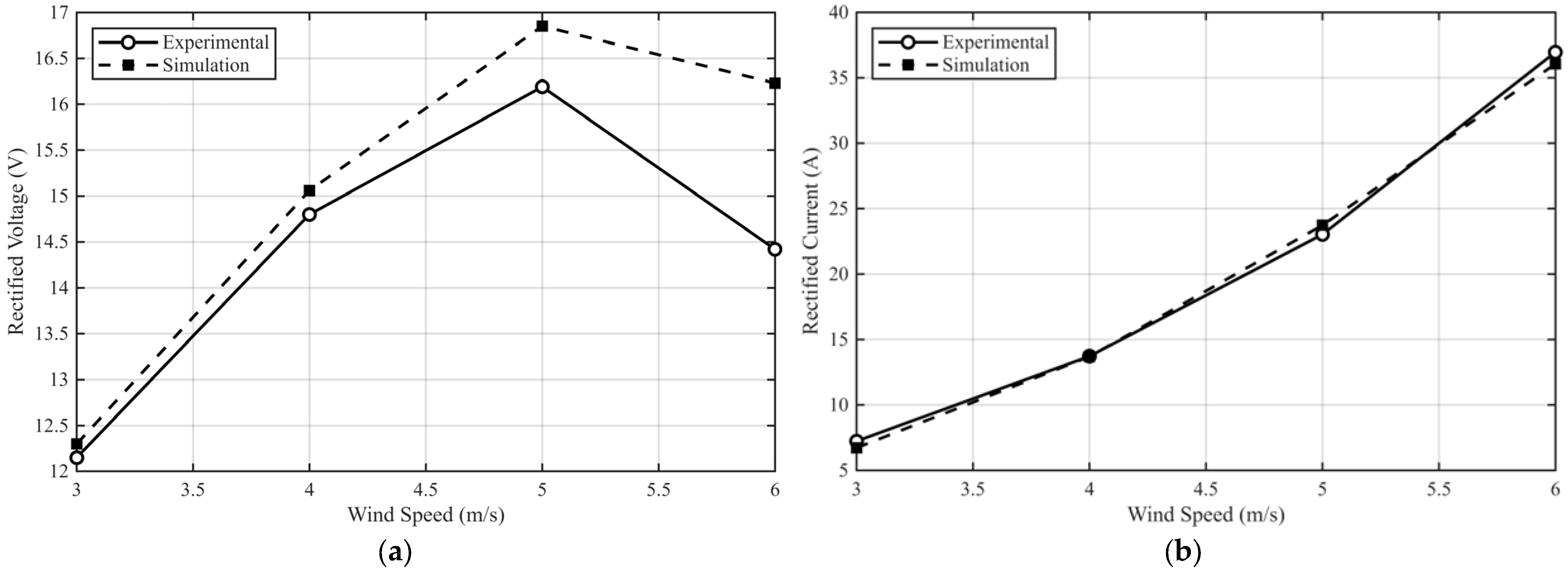
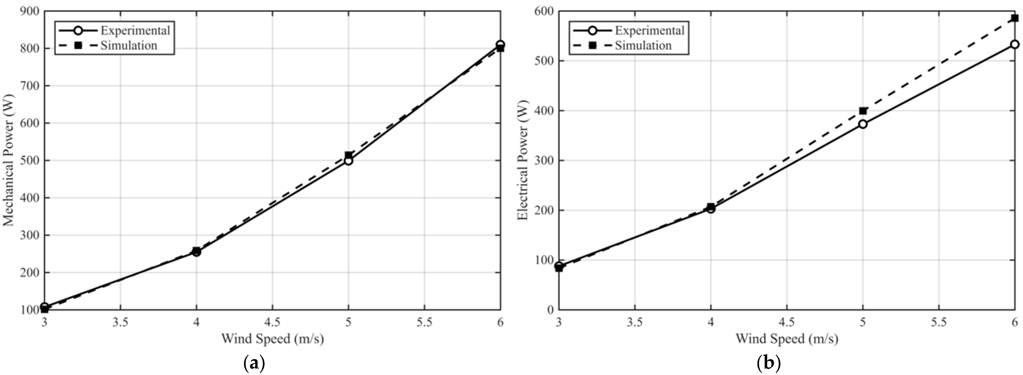
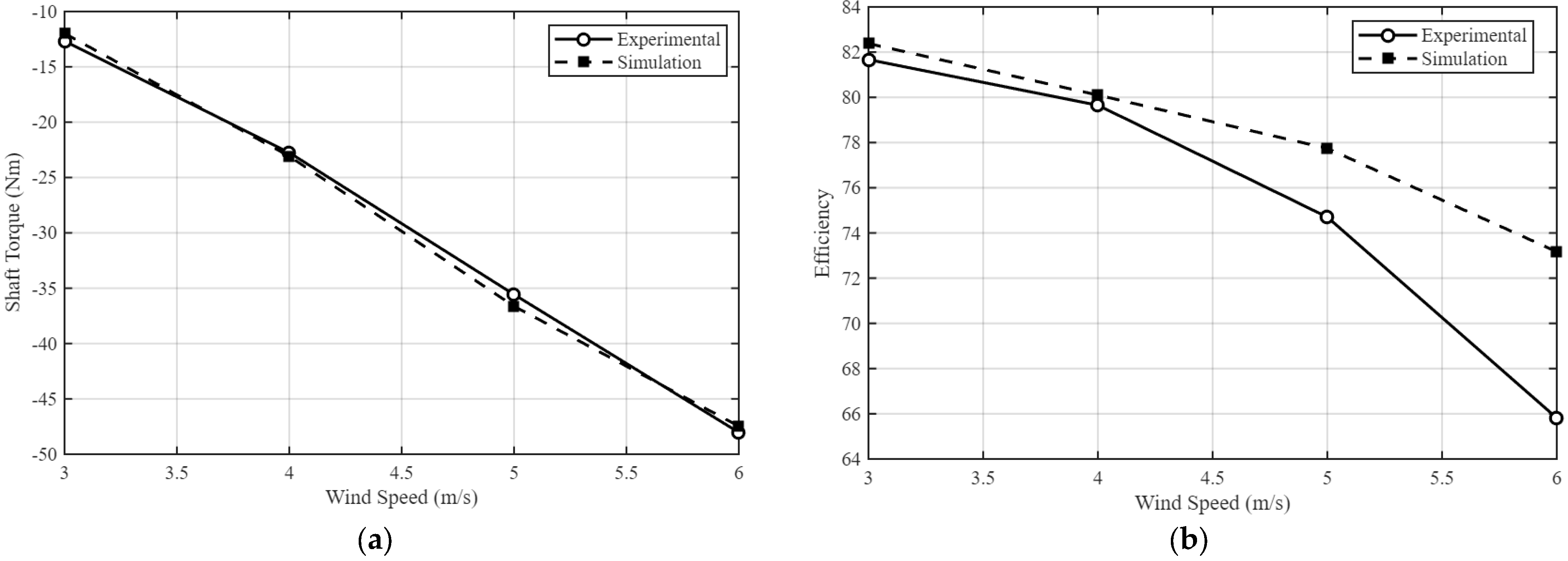
A quantitative comparison between the three-dimensional finite element results (aluminum fastening configuration) and the experimental measurements was performed over the investigated wind speed range, and the results are illustrated in Figure 15, Figure 16, Figure 17 and Figure 18 and Table 2. To ensure a consistent comparison, mechanical losses associated with bearings were excluded from the electromagnetic efficiency evaluation (Figure 15b). This is because the 3D model accounts only for electromagnetic phenomena, copper losses, iron losses and PM losses, whereas the experimental setup inherently includes additional mechanical losses.
Figure 15.
Validation of the 3D model under no-load operation: (a) simulated and measured phase voltage; (b) experimentally determined mechanical losses.
Figure 16.
Load condition comparison between 3D simulation and experimental results: (a) phase voltage; (b) phase current.
Figure 17.
Load condition comparison between 3D simulation and experimental results: (a) mechanical power; (b) electrical power.
Figure 18.
Load condition comparison between 3D simulation and experimental results: (a) electromagnetic torque; (b) efficiency.
Table 2.
Comparison between experimental results and 3D simulation under no-load and load conditions.
A slight reduction in the measured phase voltage compared to the 3D simulation results was observed at higher operating points. One contributing factor is related to the output connection cables used in the experimental prototype. As the load increases, the phase current rises accordingly, amplifying this additional voltage drop. Since the 3D finite element model evaluates the induced voltage directly at the stator terminals and does not include external connection resistances, this effect contributes to the slightly lower experimentally measured voltage values. Another contributing factor could be the larger equivalent air gap for the prototype machine compared to the simulated one. A larger distance between the PMs and rotor magnetic poles could contribute to an increased equivalent air gap.
For wind speeds up to 4 m/s, the agreement between simulation and experiment is very good, being below 1% for the main performance indicators. This very small discrepancy confirms the accuracy of the electromagnetic model and validates the geometric and material assumptions adopted in the 3D simulation.
At higher wind speeds, particularly beyond 4 m/s, slightly larger differences can be observed in the phase voltage. These deviations become more noticeable at 6 m/s, where the experimentally measured efficiency reaches approximately 66%, compared to 73% predicted by the 3D model. As the performance of the generator degrades beyond a wind speed of 6 m/s, the experiments were limited to this wind speed level. This corresponds to an optimum operation at low and medium wind speeds for this machine. The generator could work more efficiently at higher wind speeds, but the rotor speed should be increased.
The efficiency of the energy conversion system was evaluated as the ratio between the electrical power delivered to the load and the mechanical power supplied to the generator shaft. The efficiency is calculated as:
where η represents the overall efficiency of the generator system (%), is the electrical output power delivered to the load (W), and is the mechanical power provided at the generator shaft (W).
The electrical power is determined from the rectified voltage and current measured at the load:
where is the rectified voltage across the load (V) and is the rectified current flowing through the load (A).
The mechanical power is calculated from the shaft torque and the angular speed of the generator rotor:
where T is the shaft torque (Nm) and ω is the angular velocity (rad/s), obtained from the rotational speed n as:
4. Discussion
The obtained results demonstrate that structural components not originally considered part of the magnetic circuit can significantly influence the electromagnetic behavior of flux-concentrating permanent magnet machines. In the initial 2D model, the fastening screws were included in the geometry, but no additional losses or noticeable flux distortion were predicted in their region. Because the 2D approach neglects axial flux components, the electromagnetic influence of these structural elements could not be properly represented, leading to an underestimation of their impact.
The reduction of approximately 10.6% in the no-load phase voltage and the additional 3 W loss component under no-load conditions confirm that even relatively small ferromagnetic structural elements can alter the magnetic field distribution in spoke-type topologies. These machines rely on flux concentration principles, and any parasitic magnetic path reduces the intended flux guidance toward the air gap. Consequently, torque capability and electrical power decrease under identical operating conditions.
The comparison between 2D and 3D simulations further reveals the limitations of planar models for compact machines with short axial length. The 2D model overestimated the induced voltage by approximately 25% compared to the 3D model.
Experimental validation confirms the reliability of the 3D model. For low power, the deviation between simulation and experiment remained below 1% for the main performance indicators. At higher wind speeds, larger differences were observed, particularly in efficiency (66% measured versus 73% predicted at 6 m/s). These deviations are explained by additional resistive voltage drops in the external connection cables, but also by a possible larger equivalent air gap for the experimental machine compared to the modelled one. Unfortunately, the generator built cannot achieve the rated power, due to the lack of 3D simulations before fabrication, which could have revealed problems not visible in 2D simulations. For this reason, the performance of our generator is below average.
Table 3 presents a comparison of the test results for this generator with the experimental results reported in two other papers. In [10], an interior spoke-type rotor generator is designed and tested. The authors of [19] present the experimental results for a “classical” surface-mounted permanent magnet machine. It is clear that there is room for improvement for the developed generator.
Table 3.
Performance comparison between the built generator (first line) and two other machines presented in the state of the art.
A calculation to determine the amortization of the cost of the generator is also presented. In Table 4, the costs for the fabrication of the machine are estimated. Considering the price of electricity in Romania, which is around 0.22 EUR/kWh, about 3300 kWh of electricity should be produced before the cost of the generator is amortized. The duration depends on the location of the wind turbine, i.e., the average wind speed.
Table 4.
Estimated cost of generator fabrication.
Overall, the study confirms that accurate modeling of structural details is crucial for flux-concentrating outer-rotor permanent magnet generators. Future work may focus on integrated electro-mechanical optimization, including structural materials with controlled magnetic permeability and thermal analysis under continuous rated operation.
Author Contributions
Conceptualization, S.B.; methodology, S.B.; software, M.D. and M.C.; validation, M.D., M.C. and S.B.; formal analysis, S.B. and A.-A.P.; investigation, S.B.; resources, S.B. and A.-A.P.; data curation, M.D.; writing—original draft preparation, M.C.; writing—review and editing, S.B.; supervision, A.-A.P.; project administration, A.-A.P.; funding acquisition, S.B. and A.-A.P. All authors have read and agreed to the published version of the manuscript.
Funding
This research has been supported by the COFUND-LEAP-RE-MiDiNA project, grant No. 12, 01/04/2024, funded by UEFISCDI, Romania.
Institutional Review Board Statement
Not applicable.
Informed Consent Statement
Not applicable.
Data Availability Statement
The original contributions presented in the study are included in the article, further inquiries can be directed to the corresponding author.
Acknowledgments
During the preparation of this manuscript, ChatGPT-5.2 was used to assist in drafting parts of the abstract and conclusions. The authors have reviewed and edited the output and take full responsibility for the content of this publication.
Conflicts of Interest
The authors declare no conflicts of interest.
Abbreviations
The following abbreviations are used in this manuscript:
| EMF | Electromotive force |
| 2D | Two-dimensional |
| 3D | Three-dimensional |
| PMs | Permanent magnets |
| η | efficiency |
| Pel | Electric Power |
| Pmec | Mechanical Power |
| Vrect | Rectified Voltage |
| Irect | Rectified Current |
| ω | Angular Velocity |
| n | Rotational Speed |
Appendix A
Figure A1.
B-H characteristics of the proposed generator’s components: (a) 50JN400 electrical steel sheets; (b) S10C structural steel; (c) temperature-dependent demagnetization curves of the Neorec42SH permanent magnet.
References
- Hau, E.; von Renouard, H. Wind Turbines: Fundamentals, Technologies, Application, Economics; Springer: Berlin/Heidelberg, Germany, 2013. [Google Scholar]
- Ackermann, T. Wind Power in Power Systems; Wiley: Chichester, UK, 2012. [Google Scholar]
- Khaligh, A.; Onar, O.C. Energy Harvesting: Solar, Wind, and Ocean Energy Conversion Systems; CRC Press: Boca Raton, FL, USA, 2017; Available online: https://www.scirp.org/(S(ny23rubfvg45z345vbrepxrl))/reference/referencespapers?referenceid=1174709 (accessed on 19 January 2026).
- Celik, A.N. Techno-economic analysis of autonomous PV–wind hybrid energy systems using different sizing methods. Energy Convers. Manag. 2003, 44, 1951–1968. [Google Scholar] [CrossRef] [Scilit]
- Bhandari, B.; Lee, K.-T.; Lee, C.S.; Song, C.-K.; Maskey, R.K.; Ahn, S.-H. A novel off-grid hybrid power system comprised of solar photovoltaic, wind, and hydro energy sources. Appl. Energy 2014, 133, 236–242. [Google Scholar] [CrossRef] [Scilit]
- Manwell, J.F.; McGowan, J.G.; Rogers, A.L. Wind Energy Explained: Theory, Design and Application; Wiley: Chichester, UK, 2010. [Google Scholar]
- Burton, T.; Sharpe, D.; Jenkins, N.; Bossanyi, E. Wind Energy Handbook; Wiley: Chichester, UK, 2011. [Google Scholar]
- Polinder, H.; van der Pijl, F.F.A.; de Vilder, G.J.; Tavner, P.J. Comparison of direct-drive and geared generator concepts for wind turbines. IEEE Trans. Energy Convers. 2006, 21, 725–733. [Google Scholar] [CrossRef] [Scilit]
- Spooner, E.; Williamson, A.C. Direct-coupled, permanent-magnet generators for wind turbines. IEE Proc. Electr. Power Appl. 1996, 143, 1–8. [Google Scholar] [CrossRef] [Scilit]
- Kim, D.-H.; Pyo, H.-J.; Kim, W.-H.; Lee, J.; Lee, K.-D. Design of spoke-type permanent magnet synchronous generator for low-capacity wind turbine. Machines 2023, 11, 301. [Google Scholar] [CrossRef] [Scilit]
- Jeong, M.-J.; Lee, K.-B.; Pyo, H.-J.; Nam, D.-W.; Kim, W.-H. Rotor shape design of spoke-type permanent magnet synchronous machines. Energies 2021, 14, 3758. [Google Scholar] [CrossRef] [Scilit]
- Dosiek, L.; Pillay, P. Cogging torque reduction in permanent magnet machines. IEEE Trans. Magn. 2007, 43, 1565–1571. [Google Scholar] [CrossRef] [Scilit]
- Boldea, I. Variable Speed Generators; CRC Press: Boca Raton, FL, USA, 2006. [Google Scholar]
- Mueller, M.A.; McDonald, A.S. A lightweight low-speed permanent magnet electrical generator for direct-drive wind turbines. Renew. Energy 2009, 12, 768–780. [Google Scholar] [CrossRef] [Scilit]
- El-Refaie, A.M. Fractional-Slot Concentrated-Windings Synchronous Permanent Magnet Machines: Opportunities and Challenges. IEEE Trans. Ind. Appl. 2010, 57, 107–121. [Google Scholar] [CrossRef] [Scilit]
- Shah, S.Q.A.; Hahn, I. Comparative analysis of surface mounted and flux focusing type axial flux permanent magnet motor. In Proceedings of the 8th IET International Conference on Power Electronics, Machines and Drives, Glasgow, UK, 19–21 April 2016; pp. 1–4. [Google Scholar]
- Polinder, J.H.; Kamper, M.J. Design optimization of directly grid-connected PM machines for wind energy applications. IEEE Trans. Ind. Appl. 2015, 51, 2949–2958. [Google Scholar] [CrossRef] [Scilit]
- Pyrhönen, J.; Jokinen, T.; Hrabovcova, V. Design of Rotating Electrical Machines; Wiley: Chichester, UK, 2014. [Google Scholar]
- Kudrjavtsev, O.; Vaimann, T.; Kilk, A.; Kallaste, A. Design and prototyping of outer rotor permanent magnet generator for small scale wind turbines. In Proceedings of the 18th International Scientific Conference on Electric Power Engineering (EPE), Kouty nad Desnou, Czech Republic, 17–19 May 2017. [Google Scholar]

Disclaimer/Publisher’s Note: The statements, opinions and data contained in all publications are solely those of the individual author(s) and contributor(s) and not of MDPI and/or the editor(s). MDPI and/or the editor(s) disclaim responsibility for any injury to people or property resulting from any ideas, methods, instructions or products referred to in the content. |
© 2026 by the authors. Licensee MDPI, Basel, Switzerland. This article is an open access article distributed under the terms and conditions of the Creative Commons Attribution (CC BY) license.