Abstract
Small combustion installations (SCIs) burning solid fuels remain a major source of particulate matter (PM) emissions responsible for winter smog episodes in many European regions. This study aimed to develop and validate low-cost, micro-scale electrostatic precipitators (ESPs) suitable for retrofitting residential SCIs, and to quantify their PM removal performance under both controlled laboratory conditions and real-life field operation. Two ESP variants were designed and prototyped: (i) a tubular in-line ESP for installation at the boiler flue outlet and (ii) a disk (chimney-bypass) ESP mounted at the chimney outlet, with low energy demand. PM concentrations upstream and downstream of the ESPs were measured using standardized gravimetric, isokinetic sampling with recalculation to reference conditions, and the overall dedusting efficiency was determined from inlet/outlet concentrations. Laboratory testing showed that the micro-scale ESPs can achieve high dedusting efficiencies of approximately 90% under stabilized nominal-load operation. Field trials of the disk ESP in households and small residential buildings confirmed robust performance, with dedusting efficiencies of 70–82% under unsupervised user operation. In most cases, outlet PM concentrations were reduced below applicable Ecodesign thresholds. The results confirm that micro-scale ESPs are a technically feasible and effective “end-of-pipe” option for reducing short-stack PM emissions from solid-fuel heating, offering immediate air quality benefits where appliance replacement or fuel switching is limited by cost or practical constraints. This paper discusses the latest advancements in reducing PM emissions from SCIs. It introduces a prototype design for two types of micro-scale electrostatic precipitators (ESPs) that can be integrated into SCIs that burn solid fuels. The proposed technical solution utilizes an electrostatic method to effectively remove PM from flue gases. An established industrial technology has been adapted to meet the specific technical, economic, and safety needs of residential applications. The paper compares two design variants with a novel self-cleaning mechanism through laboratory testing and presents results from field trials. Findings confirm ESPs can substantially reduce PM emissions from SCIs.
1. Introduction
During the autumn and winter seasons, numerous regions across Poland and Europe experience elevated levels of airborne dust, commonly referred to as smog [1]. The deterioration in air quality is linked to high concentrations of particulate matter and toxic pollutants, such as benzo(a)pyrene and other polycyclic aromatic hydrocarbons (PAHs) [2,3,4]. In smog incidents, all acceptable standards defined by the World Health Organization or established by the NEC Directive are exceeded (Figure 1). The greatest risk of smog occurrence is associated with densely populated urban areas as well as mountain valleys, where both inadequate ventilation and high emissions from transport and/or domestic heating are prevalent [5,6,7]. In Poland, the regions at the highest risk of smog are the southern provinces (Małopolskie, Śląskie), where domestic heating relies on the combustion of solid fuels (primarily hard coal) in small combustion installations.
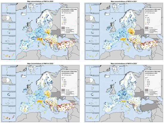
Figure 1.
PM10 daily concentrations in Europe between 2020 and 2023 [8]. Concentration of PM10 in 2023 available in Appendix A, Figure A1.
Recent advances in ESP technology have significantly expanded applications beyond traditional domestic heating systems into diverse environmental control and industrial domains. Lee et al. [9] demonstrated that a novel two-stage ESP with dry-cleaning apparatus achieved 99.4% collection efficiency for PM1 particles in building ventilation systems, with field demonstrations in subway stations showing near-perfect restoration of collection efficiency to initial states after dry-cleaning cycles. Similarly, Wang et al. [10] developed a cylindrical ESP (C-ESP) for portable air purifiers that achieved 94.6% filtration efficiency for PM0.3 particles while reducing carbon emissions by 30.0% compared to commercial HEPA filters and lowering annual usage costs by 23.2%. Andrade and Guerra [11] enhanced nanoparticle collection using wire screens as additional collecting electrodes, achieving collection efficiencies exceeding 70% for ultrafine particles and maximum efficiencies reaching 99% under optimized operating conditions. Igarashi and Kawada [12] improved particle reduction efficiency in cylindrical ESPs through controlled gas suction around central rod electrodes, obtaining over 90% particle reduction efficiency at lower applied voltages of 2 kV when combined with suction flow rates of 18 L/min. Molchanov et al. [13] achieved combined control of PM and NOx emissions from small-scale combustion, demonstrating 99.99% PM removal efficiency and 38% NOx removal at 11 kV, achieving compliance with Ecodesign Directive limits for pellet heating units. Sheng and Yue [14] applied high-frequency acoustic agglomeration to a two-stage ESP for submicron particle removal, boosting ESP filtration efficiency from 87.3% to 96.6% and elevating filtration class from F7 to F9 according to the EN779 standard [15]. Wang et al. [16] developed a novel ESP with superhydrophobic coating (PVDFH-SiO2) on collection electrodes, achieving 92.5% removal efficiency for PM0.3−0.5 particles and restoring efficiency to 99.7% of initial values after cleaning, compared to 83.1% without coating. Yan and Lu [17] investigated heat recovery integration in ESPs with liquid-filled collection electrodes, revealing that buoyancy-driven liquid flow produced heat transfer coefficients 28 times higher than gas-side forced convection, demonstrating the feasibility of simultaneous particle removal and thermal energy storage. These diverse studies collectively demonstrate that ESP technology offers cost-effective, low-maintenance, and energy-efficient solutions for indoor and industrial air quality management, thermal energy recovery, combustion emission control, and specialized applications ranging from residential air purifiers to large-scale building ventilation and public transportation infrastructure. Although dedusting by means of electrostatic precipitators is a well-known separation technology, there is a lot of ongoing research aimed at the optimization of the ESP design [10,18]. A special challenge can be found in adopting this technique to certain requirements of the domestic sector. A certain gap in the current knowledge is development of the new robust and reliable “end-of-pipe” solutions—chimney ESPs that could enhance abatement of secondary, condensing aerosol emissions and would offer a high safety of operation. There are studies reporting the results of laboratory research on the dedusting efficiency of micro-ESPs used to abate PM emissions from small-scale combustion installations [19]. Fractional dedusting efficiency data for micro-ESPs are also provided. There is, however, a substantial lack of information on the performance of this technology in real-life conditions.
1.1. Selected European Union Environmental Regulations
The occurrence of smog, due to its frequent appearance, represents one of the most urgent environmental challenges confronting contemporary society. The magnitude of this problem, especially in nations characterized by high urbanization and low energy efficiency, necessitates a coordinated and comprehensive approach. A crucial component in tackling this issue is the adoption of the “Energy Efficiency First” (EE1st) [20] principle, which underpins strategies focused on enhancing air quality and curbing greenhouse gas emissions. According to this principle, prior to undertaking any energy production initiatives, efforts should concentrate on augmenting the energy efficiency of current systems and modernizing energy infrastructure.
Under the European Union policy framework, various legal regulations and financial support initiatives have been implemented to diminish the emission of harmful substances into the atmosphere. These measures aim to decrease the prevalence of inefficient heat sources, including obsolete coal-fired boilers, and to boost the energy efficiency of buildings, ultimately resulting in lower air pollution emissions and an improved quality of life for citizens.
Among the principal legal instruments in this field is the Energy Performance of Buildings Directive (EPBD), adopted by the European Parliament, which mandates member states to formulate national strategies for eliminating coal-fired boilers by 2040. This measure responds to the imperative for transforming the heating sector towards more sustainable and energy-efficient solutions. The directive requires member states to progressively phase out heating systems characterized by low energy efficiency and high pollutant emissions, including coal boilers, which are among the primary sources of smog and air pollution.
Moreover, Directive (EU) 2016/2284 on the reduction in national emissions of certain atmospheric pollutants (the NEC Directive) establishes commitments to decrease emissions of five major air pollutants: sulfur dioxide (SO2), nitrogen oxides (NOx), non-methane volatile organic compounds (NMVOC), ammonia (NH3), and fine particulate matter (PM2.5). The objective is to substantially mitigate the adverse effects of these pollutants on human health and ecosystems, particularly within the framework of climate change and environmental degradation [7,20].
Concurrently, Directive 2008/50/EC on ambient air quality and cleaner air for Europe (CAFE) establishes ambitious air quality targets, specifying permissible levels of pollutants including PM10, PM2.5, nitrogen dioxide (NO2), and sulfur dioxide (SO2). The standards set forth therein offer a framework for national initiatives designed to ensure improved air quality, thereby enhancing citizen health and safeguarding the natural environment.
In response to growing public awareness and scientific evidence, the revised Ambient Air Quality Directive (AAQD) imposes even stricter pollutant level standards, to be attained by 2030. These new regulations are designed not only to enhance air quality within the European Union but also to harmonize standards with the recommendations of the World Health Organization (WHO), with the aim of protecting human health and diminishing the risk of non-communicable diseases associated with air pollution.
The EU’s Zero Pollution Action Plan targets a reduction of more than 55% in the health impacts (premature deaths) of air pollution by 2030 compared with 2005 [21]. Despite progress, PM2.5 remains associated with a substantial health burden in Europe, including an estimated 182,000 premature deaths in the EU-27 in 2023 [22]. In many regions, wintertime PM episodes are strongly influenced by emissions from residential solid-fuel heating, making this source category a priority for high-impact mitigation.
1.2. Smog Issue in Poland
Smog is an atmospheric phenomenon associated with elevated concentrations of PM10 and PM2.5 particulate matter, i.e., particles with an aerodynamic diameter less than 10 µm and 2.5 µm, respectively [23]. According to the European Environment Agency (EEA), this issue is widespread across Europe, primarily resulting from emissions originating in the residential sector and road transport, with their respective contributions to national emissions varying in accordance with economic conditions [24].
The manifestation of smog has a decidedly detrimental effect on human health [25]. Children, pregnant women, and the elderly are especially susceptible to its adverse effects. Smog, comprising fine solid and liquid aerosols, may induce pathologies of the respiratory and vascular systems. Numerous reports by the World Health Organization and the European Environment Agency indicate that it is responsible for a substantial number of premature fatalities [26]. A particularly adverse effect is ascribed to fine dust fractions: PM2.5 inhalable particles, capable of reaching the upper respiratory tract, and respirable PM1.0, which are able to penetrate the lower respiratory tract [25]. Data from the European Environment Agency [8] indicate that more than 34,700 individuals in Poland die annually due to air pollution, primarily attributable to the effects of PM2.5.
In Poland, the allowable concentration of PM10 dust in the air, expressed as a daily average, is 50 μg/m3, while the permissible annual average is 40 μg/m3. The public is informed when the daily PM10 concentration exceeds the threshold value of 100 μg/m3, with an alarm level set at 150 μg/m3. The permissible concentration of PM2.5 dust is 25 μg/m3 (annual average). The occurrence of smog is accompanied by additional harmful atmospheric pollutants, including nitrogen oxides, carbon monoxide, polycyclic aromatic hydrocarbons, and toxic elements [27]. The latter, primarily heavy metals, are largely adsorbed on the surface of solid aerosols (suspended dust). These pollutants constitute a significant threat not only to human health but also to the environment [28,29,30]. The primary source of this adverse smog effect is the combustion of solid fuels—coal and biomass—in so-called small combustion installations of outdated design [31]. Such installations include stoves, fireplaces, cookstoves, and boilers, which may be operated either automatically or manually, and are commonly utilized in individual households as well as municipal blocks of flats. However, significant pollutant loads also result from the combustion of liquid fuels, particularly diesel oil, in road transport [6,7]. In Poland, the majority of PM10 and PM2.5 emissions are attributed to the combustion of solid fuels in the residential sector [32]. In 2018, it was reported that the residential sector was responsible for 45.5% of PM10 emissions and 48.2% of PM2.5 emissions.
1.3. Polish Heating Sector and Local Challenges
In Poland, the heating sector, particularly individual heating, confronts multiple challenges stemming from outdated infrastructure, low energy efficiency, and consequently, high pollutant emissions. A significant number of households continue to rely on obsolete heating equipment powered by fossil fuels, primarily coal, which constitutes the predominant source of particulate emissions in the country. The municipal and household sector accounts for approximately 68% of PM10 emissions nationwide [32,33]. Despite the existence of support initiatives such as the Clean Air program (“Program Czyste Powietrze”), the rate of replacing heating devices and modernizing buildings remains insufficient. The number of outdated boilers in operation that still need to be replaced exceeds 3.5 million, alongside 2.5 million local space heaters currently in use. Concurrently, escalating energy poverty is becoming an increasingly pressing concern for Polish households. In 2022, various forms of energy poverty affected a considerable share of households in Poland:
- Fuel poverty (income-based): characterized by high energy costs in relation to household income (16% to 30% of households, depending on the threshold).
- Structural poverty: predominantly influencing the lowest earners who face high energy costs relative to their income (8% to 12% of households).
- Municipal poverty: stemming from inadequate infrastructure (e.g., lack of central heating) or low energy efficiency of buildings (3% to 5% of households).
- Hidden energy poverty: evident when households drastically reduce energy consumption for financial reasons, often linked to the use of outdated coal stoves (13% to 16% of households) [34].
Households experiencing financial strain frequently cannot afford the purchase of modern heating sources or the execution of energy-efficient building renovations, causing elevated heating costs and exacerbating energy exclusion. This issue is further intensified by rising energy and fuel prices, which make it increasingly challenging for many individuals to maintain proper thermal comfort in their homes.
Poland is implementing the Clean Air program, initiated in 2018, aiming to curtail pollutant emissions through the replacement of outdated heat sources with modern, low-emission technologies, coupled with improvements in building energy efficiency. Currently, the program’s objectives include upgrading the energy efficiency of 3,030,000 buildings or residential units and substituting 3,000,000 inefficient heat sources with low-emission alternatives. According to periodic updates, between 19 September 2018 and 23 April 2024, encompassing 5.5 years of the program’s implementation (half of its planned duration), the total number of applications for heat source replacement reached 702,482, which constitutes roughly 23.4% of the intended target. Beginning in 2025, the program will discontinue funding standalone fossil fuel boilers, in accordance with the EU EPBD [35].
1.4. Pollutants from Small Combustion Installations, Fueled by Solid Fuels
The combustion of solid fuels, particularly low-grade fuels, in outdated heating devices contributes to elevated emissions of pollutants, including products of incomplete combustion [36,37]. These combustion by-products, encompassing environmentally hazardous pollutants, are partly discharged into the atmosphere alongside flue gases and partly retained in bottom ash [38,39]. The excessive release of pollutants from small combustion installations primarily results from inefficient combustion, which is especially characteristic of simple, older devices such as fireplaces, stoves, and manually fueled boilers. The products of incomplete combustion may include [40]: NH3; CO; volatile organic compounds (VOCs)—aliphatic and aromatic hydrocarbons (benzene and its alkyl derivatives), aldehydes, ketones, phenol and its alkyl derivatives, nitrogen-, sulfur-, and oxygen-containing heterocompounds; persistent organic pollutants (POPs) including dioxins and furans (PCDD/Fs); and polycyclic aromatic hydrocarbons (PAHs), as well as carbon black within total suspended particulates (TSPs) and their sub-fractions PM10 and PM2.5. Enhanced combustion techniques and the control of fuel quality constitute the principal, fundamental strategies for reducing pollutant emissions [41]. Proper combustion parameter management applies the “3T” principle [42], denoting three key factors [43] that exert a significant influence on the combustion of solid fuels:
- Temperature—the kinetics of both homogeneous and heterogeneous combustion necessitates maintaining a sufficiently high temperature in the chemical reaction zone.
- Turbulence—efficient combustion, particularly in the secondary (gaseous) phase, must proceed in a turbulent flow regime to ensure a high mixing rate of the reactants.
- Time—complete combustion can be attained only if the fuel remains within the chemical reaction zone for a sufficiently long period.
By incorporating these parameters, the energy and environmental performance of modern heating appliances can be considerably enhanced [44,45,46] in comparison to older, highly emissive, and inefficient devices. The environmental impacts of different SCIs fueled by coal is presented in Table 1 [47].

Table 1.
Emission factor, g/GJ, *PCDD/F ng/GJ.
The stringent new requirements laid out by product standards under the ErP Directive have driven substantial improvements in appliances entering the European market. These standards form the primary method of replacing existing equipment, and their key provisions are summarized in Table 2.
Table 2.
Ecodesign requirements on energy and environmental performance (1). Table reproduced based on Commission Regulation 2015/1189 of 28 April 2015 [48].
Current EU Ecodesign requirements for solid-fuel boilers are set out in Commission Regulation (EU) 2015/1189, which applies to appliances placed on the market and defines emission performance requirements including particulate matter limits. However, a large legacy fleet (boilers, manual and automatic; cookers; stoves; and slow-heat-release stoves) has remained in operation for many years due to replacement costs, infrastructure constraints, and household decision cycles. As a result, cleaner ‘new’ products alone may not deliver sufficiently rapid air quality improvements in areas with a high dependence on solid fuels.
Hence, the performance of SCIs cannot be further improved by employing primary abatement measures; the ultimate measure for abating PM emissions are secondary methods, such as filters. The use of dedusting apparatus such as electrostatic precipitators is especially critical when replacing an outdated solid-fuel SCI with a modern appliance can not be considered. Various dust removal devices are available, with electrostatic precipitators deemed the most effective for capturing fine particulates, PM10 and PM2.5. This technical solution is also suitable for retrofitting existing installations.
Compact micro-ESPs provide an incremental, retrofit pathway to reduce particulate emissions without requiring fuel switching or full system replacement. Such solutions can deliver rapid exposure benefits in densely populated areas because residential heating emissions are released at low stack heights and occur when atmospheric dispersion is poor. Accordingly, ESP retrofits can complement the Ecodesign approach by addressing both newly sold boilers and the existing installed base.
1.5. VOCs as Precursors of Condensing Aerosol
The condensation range, where VOCs pass from the gas phase to the liquid phase during the cooling of the flue gases, depends mainly on their chemical composition (mainly hydrocarbons, aldehydes, and phenols). VOCs emitted from coal and woody biomass combustion in small installations (e.g., furnaces, boilers < 500 kW) do not have a single defined “dew point range” like water vapor; instead, their condensation occurs via deposition, absorption, or partitioning onto particles/aerosol during flue gas cooling below ~100–150 °C, often enhanced below the acid dew point (35–140 °C depending on fuel sulfur). For coal in small-scale boilers, the flue gas dew point (where water vapor and dissolved contaminants like VOCs begin to condense) is 35–45 °C for dry, low-sulfur coal, but it increases to 90–140 °C with higher humidity or sulfur content [49,50,51]. VOC condensation towards aerosols makes it possible to capture the secondary aerosol in dedusting systems, hence an increased pollutant removal efficiency.
2. Materials and Methods
2.1. Micro-Scale, Electrostatic Precipitators
Numerous commercial solutions for micro-electrostatic precipitators are available on the European market, with the majority of models either mounted directly to the heating device or installed at the chimney outlet. Two distinct configurations are presented here:
- Tubular electrostatic precipitators installed directly at the flue outlet of a heating device (see Figure A2 and Figure A4a in Appendix B) [45], with a wire electrode 0.5 m long, placed centrally inside the pipe of 160 mm diameter.
ESP casings, both tubular and plate design, were manufactured using stainless steel. Corona discharge was created on the discharge electrode by means of a high-voltage unit (1.5 mA @ 20 kV, DC). Electricity consumption in operating mode was around 25 Wh. Specific Collection Area (SCA) for both designs was around 5 m2/1000 m3.
Both of the presented assemblies were designed using a dedicated algorithm based on established electrostatic precipitation models, including fractional separation efficiency as described by the Deutch and the Matts-Öhnjeld equations [47]. A design was based on the assumption that small combustion installations fueled by coal emit mainly fine dust, such as PM10, while biomass-fueled appliances may emit a significant share, above 90%, of ultrafine particles such as PM1.
Intensive charging of gas and aerosol particles can be assured by an appropriate discharge current and sufficiently long residence time in the charging zone. Effective separation of dust from flue gases also depends on a short separation path towards collecting electrodes, and a sufficient collecting surface area (SCA) in m2/1000 m3 flue.
The gas velocity inside an ESP typically ranges from 1.2 to 2.4 m/s, balancing collection efficiency and re-entrainment losses. Optimum velocity narrows to 1.5–1.8 m/s and is lower for high-efficiency units (e.g., <0.8 m/s). Higher velocities reduce residence time for particle charging and migration, lowering efficiency, while velocities above 2.4 m/s increase fly ash re-entrainment from collector surfaces [52,53,54].
The optimum SCA for ESPs typically ranges from 11 to 45 m2/1000 m3 with 16.5–22 m2/1000 m3 often considered optimal for high-efficiency applications [55]. For high-resistivity dust, larger SCAs (>22 m2) are required to maintain high efficiency.
Several key parameters of the flue and particulates such as dust composition, size distribution, flue temperature and velocity, and flow profile influence the dust removal efficiency of the ESPs. To achieve the desired performance of the apparatus, they should all be taken into account by the design procedures.
Dust resistivity is the most important parameter determining dust removal efficiency. Peak resistivity: For most coal dust, the highest resistivity occurs in the range of 130–150 °C. At this temperature, electrostatic precipitator efficiency is typically lowest because the high resistance impedes charge transfer to the collecting electrode, which can lead to the phenomenon of back corona.
At higher temperatures (>250 °C) resistivity decreases due to the volume conductivity of the particles, which theoretically facilitates dust removal, but other factors (e.g., a thinner gas) impair the final result. At lower temperatures (<100 °C) resistivity decreases rapidly due to the condensation of moisture and acids (e.g., sulfuric acid) on the particle surface, improving their conductivity and device efficiency.
With increasing temperature the gas density decreases, reducing its electrical strength. As a result, the electrostatic precipitator must operate at a lower operating voltage, which weakens the electric field strength and the attractive force of the particles.
Higher temperatures result in a larger exhaust volume for the same mass flow rate. This increases the gas velocity in the electrostatic precipitator, shortening the residence time of particles in the electric field and making their capture more difficult. With increasing temperature, gas viscosity increases, which leads to increased hydrodynamic resistance for moving particles, making it more difficult for them to reach the collection electrodes. Lower exhaust gas temperatures in the range of 90–100 °C allow for significant efficiency improvements (especially for high-resistance dusts).
2.2. Measurement Methodology
All measurements were performed in accordance with the pertinent testing standards and methods. Each measurement series comprised three trials. Dust concentration and gas volume flow measurements were conducted in conformity with Polish Standards EN-PN-Z-04030-7 [56].
The dedusting efficiency was determined using the gravimetric method with internal filtration. Isokinetic sampling was performed automatically by means of a sampling unit. A uniform flow profile at the sampling point was assured by locating sampling points at standardized lengths of the pipe section. Gas flowrate and dust concentration were measured by means of an automatic gravimetric dust sampler, type P-10 ZA, equipped with the Central Measuring Unit “CJP-10,” supplied by ZAM Kęty Sp. z o.o. (Kęty, Poland) The mass of the filter inserts (bags) was measured with a non-automatic laboratory balance of accuracy class 1, type WA-32, accurate to 0.0001 g. Prior to weighing (both with and without dust), the filter inserts were dried in a laboratory oven at 105 °C for two hours until achieving a constant mass. The measured dust concentrations upstream (cin) and downstream (cout) of the dust removal devices were recalculated to reference conditions (dry gas, 10% O2 in the flue gas).
The overall efficiency of the dust collectors was then established in accordance with the following equation:
where:
- η—overall dedusting efficiency, %;
- cin—inlet concentration of dust in the dry flue gases, mg/m3dry.gas at reference oxygen level of 10% in the exhaust gases;
- cout—outlet concentration of dust in the dry flue gases, mg/m3I at reference oxygen level of 10% in the exhaust gases.
The uncertainty budget of the dust concentration measurement in exhaust gases (according to the relevant standard) includes components related to the mass of dust, gas volume (in actual and standard conditions), pressure, temperature and flow standardization. Uncertainty components were defined as follows:
Dust concentration (where is a mass of dust separated on a filter, is a volume of flue gases sampled in standard conditions) is dependent on the filter weighing uncertainty (balance calibration, drift, resolution: 0.1 mg) and gas volume measurement.
The volume from the orifice flow meter is determined from the parameters: (temperature), (pressure), (pressure drop), density from .
—the uncertainty here results from pressure fluctuations (Pa), temperature (°C), and calibration (m3).
Standardization to normal conditions (273 K, 1013 hPa) introduces uncertainty from (flue pipe), achieving the total standard uncertainty.
Uncertainty of electrostatic precipitator dust removal efficiency is as follows:
The uncertainty of the methods adopted was defined as expanded uncertainty. The coverage factor is k = 2; the confidence level is 95%. Expanded uncertainty was ~12% for the dust concentration measurement and ~17% for dedusting efficiency.
2.3. Laboratory Set-Up for ESP Testing
Both micro-electrostatic precipitator configurations were subjected to laboratory tests aimed at identifying key process parameters, including dedusting efficiency. The laboratory setup is described in Appendix C. Measurements were carried out for the two types of coal boilers—an automatic coal boiler and a manually fueled coal boiler with a power rating of up to 25 kW. During the testing both appliances were operated at nominal load, except for the startup phase test, carried out for tubular ESP and manual coal boiler setup. Testing was carried out at different excess air ratios to simulate good and bad combustion conditions. Flue temperature at the inlet to the ESPs varied between 140 °C and 150 °C for the manual boiler operating at nominal load and 55–75 °C for startup phase. For the automatic boiler at nominal load, measured inlet temperature range was slightly lower, i.e., 120–130 °C. Flue flowrates (at actual conditions) in the measurement conduit were also different for both appliances, predominantly due to different excess air ratios (λ ranging between 1.6 for good combustion and ~2.5 for poor combustion; O2 8–14% respectively). They were around 130 m3act./h and 160 m3act./h for the automatic boiler operating under good and poor combustion conditions and 155–250 m3act./h for the manual boiler. For startup phase of the manual boiler, flue flowrates varied within the range of 55–65 m3act./h. Flowrate variability, as well as different designs of the ESP (tubular vs. plate), determined different flue velocities inside the dedusting apparatus. For tubular ESP, velocities of flue gases varied between 1.9 and 2.2 m/s at nominal boiler load and ~0.9 m/s for startup phase. Meanwhile, for plate ESP, velocities ranged between 1.3 and 2.5 m/s for good and poor combustion respectively. All of them fell within the range of optimum air flow velocities for well-designed ESPs.
2.4. Field Set-Up for ESP Testing
Further research on the performance of the dedusting device included monitoring of their operation in the field. During the pilot campaign, disk micro-electrostatic precipitators were installed in the individual households and blocks of flats in several municipalities of southern Poland. The aim of this was to confirm the effectiveness of the device in real conditions. In addition, comprehensive information on their operation and maintenance was collected. The field testing setup is described in Appendix D.
Measurements were carried out for different types of heating devices such as automatic coal boilers (nominal power output 20–25 kW), manual coal boilers (nominal power output 15–20 kW) and stoves including a small bakery stove (power output approximately 30 kW). During the testing, all appliances were operated by their user in a usual way and the device use was not supervised by testing staff. Therefore, load under operation was not known. Flue temperature at the inlet to the ESPs varied between 62 °C and 114 °C for the automatic boiler. For manually fueled devices, measured ESP temperature ranged between 70 and 190 °C, where the lowest value was observed for bakery stove. Flue flowrates (in actual conditions) in the measurement conduit for automatic boilers existed in a very narrow range, i.e., from 221 to 242 m3act./h, and so did flue velocities inside the ESP, ranging from 2.2 to 2.4 m/s. For manual devices, flowrate was very different, ranging from 245 to 410 m3act./h for the bakery stove. Low temperatures and very high flowrates, observed for manual devices, resulted from uncontrolled supply of combustion air resulting in very high O2 concentrations above 17% (excess air ratios λ were very high >4). For manual devices, velocities inside the ESP varied between 2.0 and 3.4 m/s, exceeding the values of optimum air flow regimen.
3. Results and Discussion
3.1. Laboratory Testing
Figure 2 presents the measured overall efficiency. The prototype tubular ESP exhibited a dedusting efficiency of approximately 30–60% (average of 46.4%, σ = 13.6%) during the boilers’ startup phase, which rose to high values around 90% (average of 86.3%, σ = 4.0%) under stabilized operation at nominal load. The disk ESP yielded slightly lower efficiency, in the range of 45–65% (average of 57.1%, σ = 7.1%) for a simple planar rod electrode and about 65%to 86% (average of 70.8%, σ = 7.3%) for a modified tooth-saw electrode. Dedusting efficiencies measured for ESPs of both types are high, despite the fact that the SCA was relatively low and a single charging field was employed.
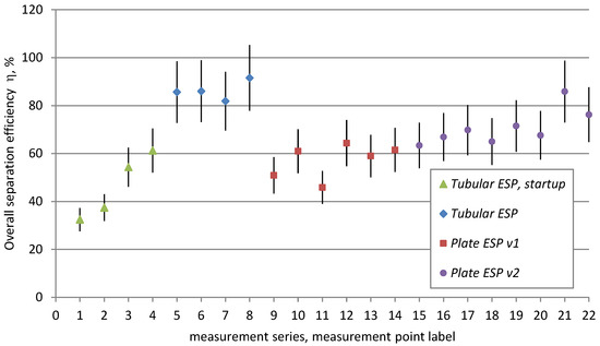
Figure 2.
Measured overall efficiency of different ESPs in laboratory testing.
Independent research institutions, including the certified testing laboratory of the Institute for Chemical Processing of Coal [57], have also verified the high efficiency of the tubular ESP. Their tests covered various designs of automatic boilers running on both hard coal and biomass (wood pellets). The results confirmed dust reduction across the entire boiler load spectrum: at minimum load, the efficiency was about 60%, while at nominal load, dust emission decreased by more than 80%.
In most measurements, high efficiency coincided with an outlet dust concentration below the Ecodesign threshold [48], as illustrated in Figure 3 (the emission requirement is indicated by the red horizontal line).
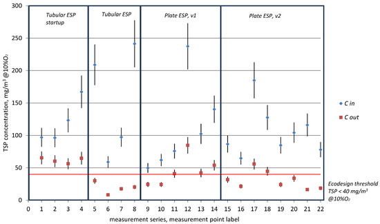
Figure 3.
Inlet and outlet dust concentration measured in laboratory testing.
Although testing conditions were similar, overall dedusting efficiencies for tubular ESPs, around 90% (point labels 5–8), were higher than for all the plate ESPs, reaching 64% for the ESP with a planar rod electrode (point label 12) and 85% for the ESP with a modified electrode (point label 21). Observed differences can therefore result only from the design of the ESPs, where the tubular ESP offers a more uniform cross-section profile of velocity when compared to plate ESPs. In addition, changing the shape of the discharge electrode in the ESP v2, by using a saw-tooth shape instead of a smooth wire, facilitates corona discharge and increases the charging efficiency of gas and dust particles. This could be a reason for why the values of dedusting efficiencies observed for plate ESP v2 (point labels 15–22) are higher than for ESP v1 (point labels 9–14).
Overall efficiency values observed for the ignition phase (point labels 1–4) at low flue velocities are lower than those observed for nominal load. Such an observation is in contradiction to base assumptions as described by the Deutch equation. Efficiencies should be higher at lower temperatures and flowrates, since resistivity of dust is lower and residence time in the charging zone is longer. The reduced efficiency during the ignition phase may be primarily caused by an uneven velocity profile across the cross-section, which results from lower gas loading (lower linear flow velocities) and leads to reduced particle charging efficiency. It may also by be associated with VOC emissions during the ignition phase and related to an unfavorable temperature profile in the exhaust duct (temperature decreasing along the length of the exhaust duct), promoting secondary aerosol condensation beyond the ESP deposition zone and upstream of the outlet sampling point (see Figure A6, Appendix D). Another factor could be a higher measurement error at low flow velocities, again caused by an uneven flow profile inside the flue pipe and hard-to-handle isokinetic sampling.
Overall efficiencies observed for nominal load operation were stable despite the fact that the manual boiler was operated in poor combustion conditions with the tubular ESP’s attached efficiencies being above 85–90% (point labels 5, 8) and for plate ESP 65–70% (point labels 12, 17, 18).
3.2. Field Testing
In field testing, the devices consistently achieved a dedusting efficiency between 70% and 82% (average of 74.3%, σ = 4.18%), mirroring the performance observed under laboratory conditions. Overall efficiencies measured for ESPs assembled on automatic boilers (point labels 1–3) were slightly higher than those obtained for manually fueled appliances (point labels 4–7).
Measured overall efficiency values are shown in Figure 4. In the vast majority of cases, similar to laboratory tests, the outlet dust concentration remained below the Ecodesign threshold [48] (Figure 5). There was only one exception, which involved a bakery furnace, where although the efficiency was high, reaching 75.9% (point label 4), the Ecodesign requirement was not met.
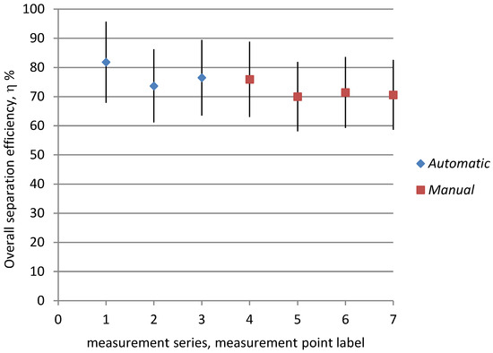
Figure 4.
Measured overall efficiency of disk ESP in field testing.
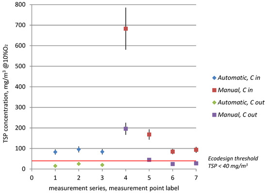
Figure 5.
Inlet and outlet dust concentration measured by tubular ESP testing.
The reason for why the emission limit value (ELV) was not achieved for the bakery furnace is the very high PM emissions from the source—high inlet concentrations to the electrostatic precipitator (point label 4). Despite the electrostatic precipitator efficiency being similar to other measurement averages (~74%), the dust removal process did not reduce the outlet concentration below the Ecodesign threshold.
4. Summary and Conclusions
This study developed and evaluated two retrofit-ready micro-scale ESP concepts intended to reduce PM emissions from small combustion installations fired with solid fuels. The primary objective was to verify whether compact, low-energy ESP designs can achieve high PM abatement efficiency not only under controlled laboratory conditions but also during real-life operation in residential settings.
Laboratory testing demonstrated that the tubular in-line ESP achieved moderate PM removal during the boiler startup period (30–60%, mean 46.4% ± 13.6%) and substantially higher efficiency under stabilized nominal load conditions, reaching approximately 90% (mean 86.3% ± 4.0%). For the chimney bypass disk ESP, overall PM removal was 45–65% with a planar rod discharge electrode (mean 57.1% ± 7.1%) and increased to 65–86% when the discharge electrode was modified to a saw-tooth geometry (mean 70.8% ± 7.3%), confirming that electrode configuration significantly affects particle charging and collection effectiveness. The results stay in compliance with the values reported by similar studies [48,52,53,54]. Notably, high efficiencies were achieved despite the use of a single-stage precipitation field and a relatively low specific collection area, supporting the feasibility of simplified micro-ESP configurations for residential applications.
Field testing of the disk ESP installed in households and small residential buildings confirmed that the technology remains effective under unsupervised, user-driven operation. Measured dedusting efficiencies ranged from 70% to 82% with a mean of 74.3% ± 4.18%, consistent with the laboratory performance of the optimized disk configuration. In most tested cases, the outlet dust concentrations were reduced to levels compliant with Ecodesign-related threshold expectations for solid-fuel appliances; the main exception occurred for a high-emitting source (bakery furnace), where high inlet PM concentrations prevented the outlet concentration from meeting the limit despite high removal efficiency.
From an implementation perspective, the tubular ESP offers a technically simpler and more-cost-effective solution, with a lower investment cost and lower energy demand (~25 W) compared with the disk chimney ESP (~48 W). Operating costs amount to 0.03 Euro/h and 0.07 Euro/h, respectively. The discrepancy primarily arises from the necessity for a flue extraction fan in the disk ESP. The higher costs associated with disk ESPs placed on the chimney stem from their operating conditions. When installed as a bypass, a disk ESP must include an additional extraction fan. Moreover, the lower temperature of flue gases at the chimney outlet raises the risk of water vapor and inorganic acid condensation, which necessitates the use of corrosion-resistant materials. When evaluating different types of developed devices, tubular ESPs offer a technically simpler solution. However, the disk chimney ESP provides broader retrofit potential, including for stoves and fireplaces, and may offer additional benefits in controlling secondary, condensable aerosol formation due to operation at lower flue gas temperatures near the chimney outlet.
Both the disk and tubular ESP variants can be integrated into current installations. This allows for an immediate, direct ecological benefit by reducing short-stack emissions (chimney height < 40 m) from the residential sector, which contribute substantially to smog during the heating season. Micro ESPs thus represent an effective alternative to other technical approaches, such as fuel substitution, connection to a district heating network, or replacement of heating appliances. When installed with existing systems, these precipitators achieve dust emission levels aligned with the ErP Directive’s thresholds [48].
The European Commission has launched and advanced a review of Ecodesign and energy labeling requirements for solid-fuel boilers, including a public consultation initiated on 28 September 2023 [58,59]. As regulatory limits tighten, performance under practical, variable household operation becomes increasingly critical, particularly during transient phases (startup, cycling) where PM peaks can occur. Micro-ESP research provides evidence on achievable reductions under controlled and field conditions, supporting technology readiness and regulatory implementation. ESPs seem to adequate technologies for achieving the stricter future requirements as adopted by the draft of the new Ecodesign requirements, proposed by the EC. Micro-scale ESPs represent a transition technology that can shorten the time between policy ambition and measurable air quality improvements. They are deployable with relatively little disruption, scalable across existing installations, and potentially compatible with future stricter Ecodesign thresholds. Therefore, ESP development strengthens the toolbox for municipalities and national clean-air programs, especially in regions where solid fuels remain prevalent and rapid PM reductions are urgently needed.
5. Patents
This research is a result of the Polish patents:
- Prototypowy elektrofiltr rurowy, dla kotłów na paliwa stałe o mocy do 30 kW, patent PL P-409498, 2014, „Urządzenie do elektrostatycznego wydzielania pyłu ze spalin z instalacji spalania paliw stałych małej mocy” [Prototype tubular electrostatic precipitator for solid-fuel boilers with a capacity of up to 30 kW, patent PL P-409498, 2014, “Device for electrostatic dust separation from flue gases in low-power solid fuel combustion installations”] [45].
- Prototypowy elektrofiltr płytowy, Patent nr 233521 z dn.06.06.2019 pt. „Sposób i urządzenie do odpylania spalin z instalacji spalania malej mocy, opalanych węglem i biomasą”, zgłoszenie nr P.419820 z dn. 15.12.2016r. [Prototype plate electrostatic precipitator, Patent No. 233521 dated 6 June 2019, titled “Method and device for dedusting flue gases from low-power combustion installations fueled by coal and biomass,” application No. P.419820 dated 15 December 2016] [46].
Author Contributions
Conceptualization, R.K.; methodology, R.K. and K.K.; investigation, R.K., K.K., W.P. and J.D.; data curation, R.K., K.K., W.P. and J.D.; resources, R.K., M.J. and M.T.; writing—original draft preparation, R.K.; writing—review and editing, M.J., W.P., J.D. and M.T.; visualization, W.P. and J.D.; supervision, R.K.; project administration, R.K. and M.T.; funding acquisition, R.K. All authors have read and agreed to the published version of the manuscript.
Funding
The authors gratefully acknowledge the funding support given by Silesian University of Technology BK/RCh/2025. This paper was partially carried out as part of the statutory research activity of the Mineral and Energy Economy Research Institute of the Polish Academy of Sciences. This research was partially financed from the subsidy of the Ministry of Education and Science for the University of Agriculture in Krakow for the year 2026.
Data Availability Statement
All sources of data are provided where necessary. Any other information is duly available from the first author—Robert Kubica—or second corresponding author—Wiktor Pacura—upon reasonable request.
Conflicts of Interest
The authors declare no conflicts of interest.
Abbreviations
| η | overall dedusting efficiency [%] |
| 3T | temperature, turbulence and time |
| AAQD | Ambient Air Quality Directive |
| CO | carbon oxide |
| EE1st | Energy Efficiency First |
| EEA | European Environment Agency |
| ELV | emission limit value |
| EPBD | Energy Performance of Buildings Directive |
| ESP | electrostatic precipitator |
| ErP Directive | Energy-related Products Directive |
| EU | European Union |
| NEC Directive | National Emission reduction Commitments Directive |
| NH3 | ammonia |
| NMVOC | non-methane volatile organic compounds |
| NO2 | nitrogen dioxide |
| NOX | nitrogen oxides |
| OGC | Organic Gaseous Compounds |
| PAH | Polycyclic Aromatic Hydrocarbons |
| PCDD | polychlorinated dibenzo-p-dioxins |
| PM | particulate matter |
| PM2.5 | particulate matter with an aerodynamic diameter less than 2.5 µm |
| PM10 | particulate matter with an aerodynamic diameter less than 10 µm |
| POP | persistent organic pollutants |
| SCIs | small combustion installations |
| SO2 | sulfur dioxide |
| TSP | total suspended particulates |
| VOCs | volatile organic compounds |
| WHO | World Health Organization |
Appendix A

Figure A1.
Daily PM10 concentrations in Europe in 2023. Source: European Environment Agency, Europe’s air quality status 2024.
Figure A1.
Daily PM10 concentrations in Europe in 2023. Source: European Environment Agency, Europe’s air quality status 2024.

Appendix B
In the variant combined with the heating appliance (a tubular ESP, constructed from 1.4307-grade stainless steel), the discharge electrode (element 3, Figure A2) typically takes the form of an elongated, rigid wire placed within a ceramic insulator (element 4, Figure A2) inside the exhaust gas duct. This electrode is powered by a direct-current high-voltage supply (20 kV) from the generator (element 1, Figure A2). By delivering shielding air through ventilation openings (element 6, Figure A2) via the central pipe (element 5, Figure A2), the emission electrode is safeguarded against dust-related damage. Cleaning of the collecting electrode and the inner surface of the ESP (element 2, Figure A2) is performed by a mechanical system using a brush (element 7, Figure A2), which is driven by an electric motor (element 8, Figure A2). The detached dust particles then descend into the ash pan (element 9, Figure A2), from which they are removed periodically by the user.

Figure A2.
A design of the tubular ESP. Source: Kubica Robert, “Device for electrostatic dust separation from flue gases in low-power solid fuel combustion installations,” PL P-409498, 2014 [45].
Figure A2.
A design of the tubular ESP. Source: Kubica Robert, “Device for electrostatic dust separation from flue gases in low-power solid fuel combustion installations,” PL P-409498, 2014 [45].

A disk micro-electrostatic precipitator (Figure A3), constructed from 1.4307-grade stainless steel, is equipped with an extraction fan (element 1, Figure A3). Once the temperature in the chimney reaches the set threshold, the fan draws flue gas into the disk micro-electrostatic precipitator body—bypass—through the inlet channel (element 2, Figure A3). The high-voltage supply, connected to the discharge electrode (element 3, Figure A3), initiates corona discharge and ionization, first of the flue gas and subsequently of the entrained dust particles.
Ionized dust settles on the collecting electrode (element 4, Figure A3), comprising three disks mounted on a shaft driven by a low-speed motor (element 5, Figure A3). Regeneration of the settling surface occurs as the disks rotate, allowing the dust layer to be scraped off by special scrapers (element 6, Figure A3). The dislodged dust then accumulates in the ash pan (element 7, Figure A3), which needs to be emptied periodically by the user. In addition, the cleaning mechanism features a mallet system (element 8, Figure A3), periodically striking the discharge electrode to loosen and remove accumulated dust. Owing to the specific construction of the housing, the flue gas flows through two ionization zones, thereby maximizing use of the collecting electrode surface. Once cleaned, the flue gas stream is directed back to the main chimney through the outlet duct (element 9, Figure A3).
The extraction fan, responsible for driving the flue gas flow through the bypass, begins operation when the flue gas temperature in the chimney exceeds 42 °C (based on a temperature sensor in the chimney). The discharge electrode is activated after reaching 45 °C, ensuring adequate warming of the ESP body before operation and thus preventing sparking associated with water vapor condensation.

Figure A3.
A design of the disk ESP. Kubica Robert, “Method and device for dedusting flue gases from low-power combustion installations fueled by coal and biomass,” P. 419820, 2016 [46].
Figure A3.
A design of the disk ESP. Kubica Robert, “Method and device for dedusting flue gases from low-power combustion installations fueled by coal and biomass,” P. 419820, 2016 [46].


Figure A4.
Pictures of the ESP during operation; (a) laboratory testing, (b) field testing.
Figure A4.
Pictures of the ESP during operation; (a) laboratory testing, (b) field testing.

Appendix C
The experimental setup (Figure A5) comprised the following elements:
- A solid-fuel boiler (item 1, Figure A5), specifically an automatic coal boiler with a nominal power output of 30 kW and a manually fueled coal boiler with a power rating of up to 25 kW;
- A dedusting device (item 2, Figure A5) (tubular ESP and disk ESP variants);
- A high-voltage generator with a control unit (item 3, Figure A5);
- Measurement sections featuring M64 nozzles at the ESP inlet and outlet (items 5, Figure A5).
The installation was fitted with all requisite control and measurement apparatus, including:
- A flue gas composition analyzer;
- A flowmeter equipped with a Prandtl probe, as well as thermometers and manometers.
Tests were carried out for the tubular ESP under both startup and steady-state conditions, in addition to tests on the disk ESP with two different discharge electrodes (disk ESP v1 and v2).

Figure A5.
Laboratory setup of a testing rig.
Figure A5.
Laboratory setup of a testing rig.

Appendix D
ESPs were installed on a bypass and testing was carried out according to the scheme presented in Figure A6, consisting of:
- Solid-fuel boiler (item 1, Figure A6); automatic coal boiler (nominal power output 30 kW) and manually fueled coal boiler (power up to 25 kW);
- Dedusting device (item 2, Figure A6) (disk ESP);
- High-voltage generator with controls (item 3, Figure A6);
- Extraction fan with controls (item 4, Figure A6);
- Measurement sections with standard sampling nozzles, inlet and outlet from the ESP (items 5, Figure A6).
The installation was equipped with all the necessary control and measurement equipment, including:
- Flue gas composition analyzer;
- Flowmeter with Prandtl probe, thermometers and manometers.

Figure A6.
Experimental setup of the field testing.
Figure A6.
Experimental setup of the field testing.

References
- Zgłobicki, W.; Baran-Zgłobicka, B. Air Pollution in Major Polish Cities in the Period 2005–2021: Intensity, Effects and Attempts to Reduce It. Environ. Res. 2024, 240, 117497. [Google Scholar] [CrossRef] [PubMed]
- Kurasz, A.; Święczkowski, M.; Dąbrowski, E.J.; Bachórzewska-Gajewska, H.; Tomaszuk-Kazberuk, A.; Roszkowska, S.; Dobrzycki, S.; Kuźma, Ł. The Impact of Polish Smog on Public Regional Health—Baseline Results of the EP-PARTICLES Study. J. Health Inequal. 2023, 9, 73–80. [Google Scholar] [CrossRef]
- Li, J.; Chen, T.; Zhang, H.; Jia, Y.; Chu, Y.; Yan, Y.; Zhang, H.; Ren, Y.; Li, H.; Hu, J.; et al. Nonlinear Effect of NO Concentration Decrease on Secondary Aerosol Formation in the Beijing-Tianjin-Hebei Region: Evidence from Smog Chamber Experiments and Field Observations. Sci. Total Environ. 2024, 912, 168333. [Google Scholar] [CrossRef]
- Kim, H.; Kim, J.; Kim, S.; Bang, S.; Jin, H.C.; Lee, S.H.; Kim, K.H.; Phyo, S.; Lee, J.; Kim, J.-T.; et al. Characteristics of Secondary Aerosol Formation during Shortened Multiday Reaction Experiments in a Smog Chamber: Effects of Relative Humidity and Ammonia. Sci. Total Environ. 2024, 954, 176740. [Google Scholar] [CrossRef] [PubMed]
- Casotto, R.; Skiba, A.; Rauber, M.; Strähl, J.; Tobler, A.; Bhattu, D.; Lamkaddam, H.; Manousakas, M.I.; Salazar, G.; Cui, T.; et al. Organic Aerosol Sources in Krakow, Poland, before Implementation of a Solid Fuel Residential Heating Ban. Sci. Total Environ. 2023, 855, 158655. [Google Scholar] [CrossRef]
- Pacura, W.; Szramowiat-Sala, K.; Gołaś, J. Emissions from Light-Duty Vehicles—From Statistics to Emission Regulations and Vehicle Testing in the European Union. Energies 2023, 17, 209. [Google Scholar] [CrossRef]
- Pacura, W.; Szramowiat-Sala, K.; Macherzyński, M.; Gołaś, J.; Bielaczyc, P. Analysis of Micro-Contaminants in Solid Particles from Direct Injection Gasoline Vehicles. Energies 2022, 15, 5732. [Google Scholar] [CrossRef]
- European Environment Agency. Europe’s Air Quality Status 2024; European Environment Agency: Copenhagen, Denmark, 2024. [Google Scholar]
- Lee, Y.; Kim, Y.S.; Lee, G.; Lee, H.; Kim, Y.J.; Han, B.; Kim, H.J. Development of an Electrostatic Precipitator with a Novel Dry-Cleaning Apparatus for Building Ventilation Systems. Indoor Air 2025, 2025, 9929558. [Google Scholar] [CrossRef]
- Wang, C.; Jiang, J.; Wang, P.; Kong, L.; Liu, J. Exploring the Potential of a Novel Electrostatic Precipitator as an Alternative to Air Filters in Air Purifiers. Build. Environ. 2025, 270, 112535. [Google Scholar] [CrossRef]
- Silva Araújo Andrade, R.G.; Guerra, V.G. Enhanced Nanoparticle Collection Using an Electrostatic Precipitator Integrated with a Wire Screen. Powders 2025, 4, 23. [Google Scholar] [CrossRef]
- Igarashi, S.; Kawada, Y. Effect of Applied Voltage on an Electrostatic Precipitator with Airflow and Electrostatic Force. Int. J. Plasma Environ. Sci. Technol. 2025, 19, e02009. [Google Scholar] [CrossRef]
- Molchanov, O.; Krpec, K.; Horák, J.; Kubonová, L.; Hopan, F.; Ryšavý, J. Combined Control of PM and NOx Emissions from Small-Scale Combustions by Electrostatic Precipitation. Results Eng. 2024, 24, 103255. [Google Scholar] [CrossRef]
- Sheng, Y.; Yue, Z. Submicron Particles Removal Performance Based on Acoustoelectric Agglomeration in a Two-Stage Electrostatic Precipitator. Build. Environ. 2025, 286, 113754. [Google Scholar] [CrossRef]
- EN 779:2012; Particulate Air Filters for General Ventilation—Determination of the Filtration Performance. European Committee for Standardization (CEN): Brussels, Belgium, 2012.
- Wang, C.; Yan, C.; Zhang, Z.; Liu, J.; Han, X. A Novel Electrostatic Precipitator with Superhydrophobic Coating for Enhanced Particulate Removal Efficiency Restoration. Build. Simul. 2025, 18, 2057–2066. [Google Scholar] [CrossRef]
- Yan, X.; Lu, J. Numerical Investigation of the Sensible Heat Storage in Novel Electrostatic Precipitators with Liquid-Filled Collection Electrodes. Appl. Therm. Eng. 2024, 255, 123993. [Google Scholar] [CrossRef]
- Chen, Y.-T.; Lu, C.-L.; Lu, S.-J.; Lee, D.-S. Electrostatic Precipitator Design Optimization for the Removal of Aerosol and Airborne Viruses. Sustainability 2023, 15, 8432. [Google Scholar] [CrossRef]
- Molchanov, O.; Krpec, K.; Horák, J. Electrostatic Precipitation as a Method to Control the Emissions of Particulate Matter from Small-Scale Combustion Units. J. Clean. Prod. 2020, 246, 119022. [Google Scholar] [CrossRef]
- European Union. Directive (EU) 2023/1791 of the European Parliament and of the Council of 13 September 2023 on Energy Efficiency and Amending Regulation (EU) 2023/955; Official Journal of the European Union: Luxembourg, 2023; pp. 1–111. [Google Scholar]
- European Commission. Zero Pollution Action Plan; European Commission: Brussels, Belgium, 2020. [Google Scholar]
- European Environmental Agency. Health Impacts of Exposure to Fine Particulate Matter (PM2.5); EEA Analysis, Report No. 11; European Environment Agency: Copenhagen, Denmark, 2025. [Google Scholar]
- Ofremu, G.O.; Raimi, B.Y.; Yusuf, S.O.; Dziwornu, B.A.; Nnabuife, S.G.; Eze, A.M.; Nnajiofor, C.A. Exploring the Relationship between Climate Change, Air Pollutants and Human Health: Impacts, Adaptation, and Mitigation Strategies. Green Energy Resour. 2024, 3, 100074. [Google Scholar] [CrossRef]
- Afifa; Arshad, K.; Hussain, N.; Ashraf, M.H.; Saleem, M.Z. Air Pollution and Climate Change as Grand Challenges to Sustainability. Sci. Total Environ. 2024, 928, 172370. [Google Scholar] [CrossRef]
- Donaldson, K.; Stone, V.; Clouter, A.; Renwick, L.; MacNee, W. Ultrafine Particles. Occup. Environ. Med. 2001, 58, 211–216. [Google Scholar] [CrossRef] [PubMed]
- European Environment Agency. Air Quality Statistics; European Environment Agency: Copenhagen, Denmark, 2022. [Google Scholar]
- European Environment Agency. Poland—Air Pollution Country Fact Sheet 2024; European Environment Agency: Copenhagen, Denmark, 2024. [Google Scholar]
- Mehta, S.S.; Elizabeth Hodgson, M.; Lunn, R.M.; Ashley, C.E.; Arroyave, W.D.; Sandler, D.P.; White, A.J. Indoor Wood-Burning from Stoves and Fireplaces and Incident Lung Cancer among Sister Study Participants. Environ. Int. 2023, 178, 108128. [Google Scholar] [CrossRef]
- Cornette, J.F.P.; Blondeau, J. Emissions and Levelized Cost of Urban Residential Building Heating: The Brussels Perspective. Energy Strategy Rev. 2024, 54, 101443. [Google Scholar] [CrossRef]
- Martins, N.R.; Carrilho da Graça, G. Health Effects of PM2.5 Emissions from Woodstoves and Fireplaces in Living Spaces. J. Build. Eng. 2023, 79, 107848. [Google Scholar] [CrossRef]
- Ozgen, S.; Cernuschi, S.; Giugliano, M. Experimental Evaluation of Particle Number Emissions from Wood Combustion in a Closed Fireplace. Biomass Bioenergy 2013, 50, 65–74. [Google Scholar] [CrossRef]
- Ministry of Climate and Environment. Krajowy Bilans Emisji SO2, NOx, CO, NH3, NMLZO, Pyłów, Metali Ciężkich i TZO za Lata 1990–2022 [National Emission Balance of SO2, NOx, CO, NH3, NMVOCs, Particulates, Heavy Metals, and POPs for the Years 1990–2022]; Ministry of Climate and Environment: Warsaw, Poland, 2024.
- Wielgosiński, G.; Czerwińska, J. Smog Episodes in Poland. Atmosphere 2020, 11, 277. [Google Scholar] [CrossRef]
- Lipiński, K.; Juszczak, A. Cztery Oblicza Ubóstwa Energetycznego Polskie Gospodarstwa Domowe w Czasie Kryzysu 2021–2023; Instytut Energetyki Odnawialnej: Warsaw, Poland, 2023. [Google Scholar]
- European Commission. Energy Performance of Buildings Directive; Official Journal of the European Union: Luxembourg, 2024. [Google Scholar]
- Ross, A.B.; Jones, J.M.; Chaiklangmuang, S.; Pourkashanian, M.; Williams, A.; Kubica, K.; Andersson, J.T.; Kerst, M.; Danihelka, P.; Bartle, K.D. Measurement and Prediction of the Emission of Pollutants from the Combustion of Coal and Biomass in a Fixed Bed Furnace. Fuel 2002, 81, 571–582. [Google Scholar] [CrossRef]
- Kubica, R.; Kubica, K.; Kacprzyk, W. Limitation of Black Carbon Emissions from Solid Fuel Combustion in Small Plants. Przem. Chem. 2016, 95, 472–479. [Google Scholar]
- Cao, Z.; Zhang, J.; Pan, W. A Review on Release and Transformation Behavior of Alkali Metals during High-Alkali Coal Combustion. Sustain. Energy Technol. Assess. 2024, 70, 103966. [Google Scholar] [CrossRef]
- Himanshu; Kurmi, O.P.; Jain, S.; Tyagi, S.K. Performance Assessment of an Improved Gasifier Stove Using Biomass Pellets: An Experimental and Numerical Investigation. Sustain. Energy Technol. Assess. 2022, 53, 102432. [Google Scholar] [CrossRef]
- Kubica, K.; Paradiz, B.; Dilara, P. Small Combustion Installations: Techniques, Emissions and Measures for Emission Reduction; European Commission, Joint Research Centre: Ispra, Italy, 2007. [Google Scholar]
- Mudgal, S.; Turbé, A.; Kuwahara, I.; Stewart, R.; Woodfield, M.; Kubica, K.; Kubica, R. Preparatory Studies for Eco-Design Requirements of EuPs (II) Lot 15 Solid Fuel Small Combustion Installations, Task 2: Economic and Market Analysis; European Commission, Directorate-General for Transport and Energy (DG TREN): Brussels, Belgium, 2009. [Google Scholar]
- Farokhi, M.; Birouk, M.; Tabet, F. A Computational Study of a Small-Scale Biomass Burner: The Influence of Chemistry, Turbulence and Combustion Sub-Models. Energy Convers. Manag. 2017, 143, 203–217. [Google Scholar] [CrossRef]
- Guerrero, F.; Arriagada, A.; Muñoz, F.; Silva, P.; Ripoll, N.; Toledo, M. Particulate Matter Emissions Reduction from Residential Wood Stove Using Inert Porous Material inside Its Combustion Chamber. Fuel 2021, 289, 119756. [Google Scholar] [CrossRef]
- Kubica, R.; Szubel, M.; Goryl, W.; Mirowski, T.; Filipowicz, M. Field Testing of Environmental Performance of Advanced Local Space Heaters in Reference to the EIG EMEP Emission Factors. Sustain. Energy Technol. Assess. 2022, 53, 102737. [Google Scholar] [CrossRef]
- Kubica, R.; Faferko, M. Device for Electrostatic Dust Separation from Flue Gas from Low-Power Solid Fuel Combustion Installations. Polish Patent PL229978B1, 28 September 2018. [Google Scholar]
- Kubica, R.; Bogacz, W. Method and Device for Dedusting Exhaust Gases from Low-Power Combustion Installations, Fired with Coal and Biomass. Polish Patent PL233521B1, 31 October 2019. [Google Scholar]
- Huang, Y.; Li, S.; Zheng, Q.; Shen, X.; Wang, S.; Han, P.; Liu, Z.; Yan, K. Recent Progress of Dry Electrostatic Precipitation for PM2.5 Emission Control from Coal-Fired Boilers. Int. J. Plasma Environ. Sci. Technol. 2015, 9, 69–95. [Google Scholar]
- European Union Commission. Regulation (EU) 2015/1189 of 28 April 2015 Implementing Directive 2009/125/EC of the European Parliament and of the Council with Regard to Ecodesign Requirements for Solid Fuel Boilers; Official Journal of the European Union: Luxembourg, 2015; pp. 100–114. [Google Scholar]
- Paris, E.; Carnevale, M.; Vincenti, B.; Palma, A.; Guerriero, E.; Borello, D.; Gallucci, F. Evaluation of VOCs Emitted from Biomass Combustion in a Small CHP Plant: Difference between Dry and Wet Poplar Woodchips. Molecules 2022, 27, 955. [Google Scholar] [CrossRef]
- Park, J.; Choi, S.; Lee, S. Effective Control of Condensable Particulate Matter from Coal-Fired Flue Gas Using Alkaline Sorbent and Activated Carbon. ACS Omega 2025, 10, 27023–27030. [Google Scholar] [CrossRef]
- Zhang, X.; Li, Y.; Zhang, Z.; Nie, M.; Wang, L.; Zhang, H. Adsorption of Condensable Particulate Matter from Coal-Fired Flue Gas by Activated Carbon. Sci. Total Environ. 2021, 778, 146245. [Google Scholar] [CrossRef]
- Knight, R.M.; Hocter, J.S.; Milliken, S.R.; Herkins, M.J.; Zhao, L.; Zhu, H. Development and Optimisation of Full-Scale Prototype Electrostatic Precipitators in a Laboratory for Particulate Matter Mitigation in Poultry facilities. Biosyst. Eng. 2023, 230, 71–82. [Google Scholar] [CrossRef]
- Cid, N.; Patiño, D.; Pérez-Orozco, R.; Porteiro, J. Performance Analysis of a Small-Scale Electrostatic Precipitator with Biomass Combustion. Biomass Bioenergy 2022, 162, 106500. [Google Scholar] [CrossRef]
- Badran, M.; Mansour, A.M. Evaluating Performance Indices of Electrostatic Precipitators. Energies 2022, 15, 6647. [Google Scholar] [CrossRef]
- Ahmad, S.; Smail, J. The Optimum Operation Conditions for Electrostatic Precipitator (ESP) in Particulate Emitter Industries. In Proceedings of the 2018 International Conference on Pure and Applied Science, Koya University, Koya, Iraq, 23–24 April 2018; pp. 145–153. [Google Scholar]
- PN-Z-04030-7:1994; Pomiar Stężeń i Strumienia Masy Pyłu w Gazach Odlotowych Metodą Grawimetryczną [Measurement of Dust Concentration and Mass Flow in Flue Gases by Gravimetric Method]. Polish Committee for Standardization: Warsaw, Poland, 1994.
- Matuszek, K.; Hrycko, P.; Master, J.; Łukasik, K.; Wawro, M.; Tatar, Z. Zastosowanie Elektrofiltrów w Kotłach c.o. z Automatycznym Podawaniem Paliwa Stałego. Rynek Instal. 2018, 4, 52–57. [Google Scholar]
- European Commission. Solid Fuel Boilers—Energy Efficient Products: Overview of the Review Process and Consultation Timeline; Energy Efficient Products; Publications Office of the European Union: Luxembourg, 2025. [Google Scholar]
- European Commission. Public Consultation on Ecodesign and Energy Labelling Requirements for Solid Fuel Boilers; DC Energy; Publications Office of the European Union: Luxembourg, 2023. [Google Scholar]


Disclaimer/Publisher’s Note: The statements, opinions and data contained in all publications are solely those of the individual author(s) and contributor(s) and not of MDPI and/or the editor(s). MDPI and/or the editor(s) disclaim responsibility for any injury to people or property resulting from any ideas, methods, instructions or products referred to in the content. |
© 2026 by the authors. Licensee MDPI, Basel, Switzerland. This article is an open access article distributed under the terms and conditions of the Creative Commons Attribution (CC BY) license.