Abstract
This paper proposes a reliable control strategy for dual induction motor drives using a five-leg inverter (FLI). Since the FLI has the structural characteristic where both motors share a common leg, the current of the common leg can flow at twice the magnitude of the other leg currents. To prevent this overcurrent, this paper proposes a reliable integrated control strategy for both normal and open-circuit fault conditions in the FLI. Under normal conditions, overcurrent can occur when the phase and frequency of the current for both motors are distinct; therefore, the angle controller and current limitation prevent overcurrent. In contrast, an open-circuit fault in the FLI can cause overcurrent due to altered current paths. To ensure a safe shutdown, identifying the specific location of the faulty switch is essential. Therefore, fault diagnosis is required using the stator currents. Once the fault is located, a fault-tolerant method is applied to safely stop the motors, considering both the fault location and the rated current of the common leg. Consequently, the proposed system enables reliable operation of dual induction motor drives under various conditions. The experimental results verify the effectiveness of the proposed system.
1. Introduction
As a representative AC motor, the induction motor (IM) has a robust structure, high durability, and cost-effectiveness. Thus, IM is widely used in various applications, such as compressors in home appliances, conveyor belts in industry, HVAC systems in railway vehicles, etc. In the past, IMs were directly connected to fixed-frequency power sources and operated at a constant speed. Precise speed control and efficient energy management were difficult. However, with advancements in power semiconductor technology, inverters capable of variable voltage variable frequency (VVVF) control have enabled variable-speed operation of IMs. Moreover, the development of vector control theory and advances in microprocessor technology have significantly improved the performance of IM drives. Recently, as the number of motors in systems continues to increase, research has focused on reducing system cost and volume by optimizing drive system configurations [1,2,3,4].
The five-leg inverter (FLI) is one of the topologies for driving dual IMs independently. Because of using ten switches and components, it has advantages of volume and cost compared to using two three-leg inverters. However, dual IMs are supplied from a shared voltage source, which limits the available voltage range to 0.577 Vdc [5]. By changing from a star connection to a delta connection of the IM, the range can be increased by approximately √3 times [6]. This means that the operating range of the FLI can be improved by changing the connection of the IM. The common leg, which is connected to the C-phase of dual IMs, may cause twice the current magnitude as that of the other legs [7]. This overcurrent reduces the efficiency and shortens the system lifespan. Refs. [8,9] propose an angle controller that minimizes the IC when the speeds of each IM are the same. If the load torques are the same and the phase difference is 180 degrees, the IC can be reduced to 0 A. Nevertheless, overcurrent may occur if the speeds are different.
The proposed system consists of a PFC and the FLI for the HVAC system in railway vehicles, as shown in Figure 1. Here, the PFC, such as the Vienna rectifier, is used to stably control the DC voltage used by the FLI [10,11,12]. In this paper, a control strategy to prevent the overcurrent for both normal and fault conditions is proposed. Under normal conditions, compressors in the HVAC can be driven in two cases, as shown in Figure 2: identical operation and distinct operation. When both IMs operate at identical speeds, the angle controller minimizes the IC. However, when the speeds differ, the phase difference cannot be maintained. Overcurrent can occur due to the sum of C-phase currents with different magnitudes and frequencies. Most studies on FLIs focus on cases under identical operation or do not comprehensively address the common leg overcurrent issue during distinct operation [13,14,15,16,17]. Meanwhile, fault conditions can be divided into short-circuit faults and open-circuit faults. Short-circuit faults generate large currents within a very short time; therefore, it must be isolated as quickly as possible by protection devices (e.g., fast-acting fuse, solid-state CB) [8,9,18,19,20]. In contrast, open-circuit faults block current paths, causing current distortion and increased torque ripple, which degrade overall system performance, stability, and reliability. In particular, the overcurrent can occur because the common leg cannot be properly controlled by the angle controller.
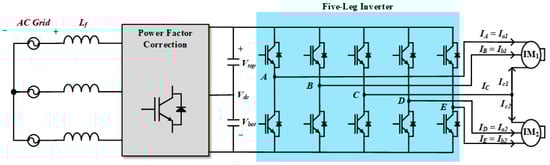
Figure 1.
Circuit for dual induction motor drive systems with five-leg inverter.
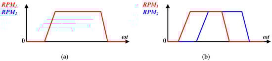
Figure 2.
Operation profile under normal conditions: (a) identical operation, (b) distinct operation.
To enhance system reliability, this paper proposes a reliable control strategy for the FLI. The proposed strategy includes an overcurrent prevention control that considers both operation conditions and open-circuit fault. The main contributions are as follows: 1. sequence-based current limitation strategy; 2. switch fault diagnosis and mitigation methods. In the sequence-based current limitation strategy, the stator currents (Isn, n = 1, 2) of both IMs are limited to less than half of its rated current (Isn,rated, n = 1, 2) to ensure that IC cannot exceed Isn,rated. Under current-limiting conditions, both motors are controlled at the same speed. Once the speeds of both IMs become synchronized, the angle controller is activated to minimize IC. In the switch fault diagnosis and mitigation methods, fault diagnosis is based on the fact that the current through a fault switch becomes zero. Consequently, the current magnitude in the stationary reference frame at the fault location becomes zero, allowing both fault diagnosis and location identification. Similarly, to prevent overcurrent after a fault, it is limited to less than half of Isn,rated. If an open-circuit fault occurs on an independent leg, the IM connected to the fault switch stops while the other IM continues to operate. If a fault occurs on the common leg, both IMs stop.
This paper is structured as follows. The principle of operation for the FLI is expressed in Section 2. Section 3 explains the operation sequence with overcurrent prevention for the proposed system. In Section 4, fault diagnosis and mitigation methods for the FLI are proposed. Section 5 presents the experimental results to confirm the validity of the proposed method. Finally, the conclusions of this paper are provided in Section 6.
2. Principle of Operation
The FLI consists of five legs with upper and lower switches as shown in Figure 3. Four legs (A-leg, B-leg, D-leg, E-leg) are connected to the A-phase and B-phase of the IM. The common leg (C-leg) is connected to the C-phase of both IMs. This C-leg configuration makes it difficult to apply the conventional PWM method. To control each IM independently, [5] proposes a double zero sequence (DZS) modulation method. The zero-voltage component consists of two parts: one for modulation range expansion and the other for independent operation. The zero-voltage obtained by injecting the third harmonic extends the voltage modulation range from 0.5 Vdc to 0.577 Vdc. Furthermore, the C-phase reference voltage (V*cn, n = 1, 2) corresponds to the zero-voltage component. The V*cn is added to the reference voltages (V*an, V*bn, V*cn, n = 1, 2) of the other IM. As a result, both IMs can operate independently. Similar to the offset voltage, this component does not appear in the line-to-line voltages and therefore does not affect the actual output.
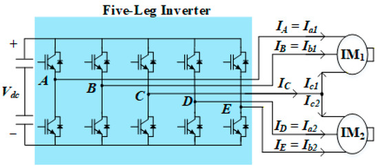
Figure 3.
Circuit of five-leg inverter.
This paper employs the field-oriented control (FOC) method [21]. The synchronous reference frame d-axis current (Iden, n = 1, 2) represents the flux, and the synchronous reference frame q-axis current (Iqen, n = 1, 2) represents the torque component. The current PI controller minimizes the error between the reference and actual currents. A speed controller regulates the IM speed by generating the I*qen that drives the speed error to 0. Both speed and current controllers are required for each IM. Since the C-leg is connected to both IMs, IC is the sum of Ic1 and Ic2. The magnitude of IC (IC,peak) can be expressed as
where δ represents the phase difference between Ic1 and Ic2. When δ = 0°, IC has up to twice the current in the other legs. In contrast, when δ = 180°, IC has its minimum. Therefore, IC can be controlled to 0 if the torque and the speed are identical. The angle controller generates the I*qen to ensure that the δ is controlled to 180° by synchronizing the electrical angular velocities (ωen, n = 1, 2) [7]. The resulting speed error is eliminated by the d-axis compensation current (I*den,comp). Figure 4 shows a control block diagram for the FLI. ωrn represents the rotor angular speed; ωsln represents the slip angular speed; θen represents the electrical angle; TIMn the represents torque of the IM; V*A, V*B, V*C, V*D, and V*E represent modulation voltages; Iden,comp represents the compensation of speed error by angle controller; and σ represents the normalized phase difference between θe1 and θe2 + δ. The mathematical definition of σ is expressed as
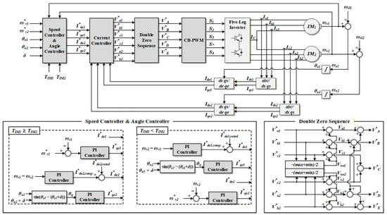
Figure 4.
Control block diagram of five-leg inverter.
Ian, Ibn, and Icn are transformed into the d-q reference frame using θen. Iden and Iqen are used as inputs to the current controller. The relationship in the angle controller varies depending on TIMn. When TIM1 is larger, I*qe1 is determined by the speed controller, whereas I*qe2 is determined such that ωe1 and ωe2 maintain δ = 180°. Although the ωen values are the same, a difference in I*qen causes a speed error. The speed error is compensated by Iden,comp, which compensates for the slip and eliminates the speed error. V*an, V*bn, and V*cn from the current controller are applied to the DZS to produce V*A, V*B, V*C, V*D, and V*E. Finally, S1, S3, S5, S7, and S9 are determined by comparing V*A, V*B, V*C, V*D, and V*E with the triangular carrier. Here, the switching state of the lower switches is the complementary operation of the upper switches.
3. Operation Sequence of FLI
In an HVAC system used in railway vehicles, the compressor normally accelerates to its rated speed (RPMrated) for stable air compression. Depending on the instantaneous cooling demand and compressed air requirements, both IMs may operate simultaneously or only a single IM may be engaged. Therefore, the operation sequence is divided into two cases: identical-speed operation and distinct-speed operation. Figure 5 shows the mechanical speed (RPM1, RPM2), Ic1, Ic2, and IC according to the operation profile. When both IMs operate identically as shown in Figure 5a, they have the same RPMs. In this case, the angle controller is activated immediately from the start because it is only effective when RPM1 and RPM2 are the same. The angle controller maintains δ = 180° between Ic1 and Ic2, thereby minimizing IC. Unlike the identical operation, the angle controller cannot always be activated in the distinct operation as shown in Figure 5b. It is only activated within RPMrated, where RPMs are identical. Specifically, the speed difference prevents a constant phase relationship between the two currents, making the angle controller ineffective. Consequently, the IC becomes the sum of Ic1 and Ic2 with different frequencies, magnitudes, and time-varying phase angles. The worst-case scenario occurs when the peaks of Ic1 and Ic2 align, causing IC,peak to reach up to twice the current in the other legs. This result often exceeds Isn,rated, leading to thermal stress, junction degradation, or failure of the switch.
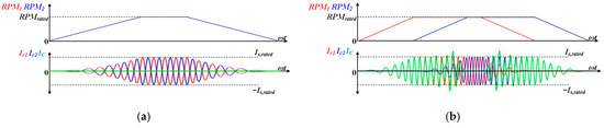
Figure 5.
RPM1, RPM2, Ic1, Ic2, and IC according to the operation profile: (a) identical operation; (b) distinct operation.
No method for minimizing IC in the FLI under different speed conditions has been reported in the literature yet. Studies either assume identical operation or do not consider the overcurrent of the C-leg. This limitation requires a separate strategy to prevent overcurrent during asynchronous operation until speed synchronization is achieved. This paper proposes a sequence-based current limitation strategy that prioritizes hardware protection over dynamic response during these transient intervals. Specifically, since IC is the sum of the Ic1 and Ic2 as expressed in Equation (1), IC can reach up to twice Isn,rated when δ = 0°. To ensure that IC does not exceed Isn,rated even in this worst case, Isn is limited to half of Isn,rated. This limitation serves two purposes. First, it prevents IC,peak from exceeding Isn,rated. Second, by limiting torque, the time to safely activate the angle controller is reduced. The q-axis current limit for operation (I*qen,lim) can be expressed as
Figure 6 shows the three-step operation sequence for accelerating IM2 while IM1 is running, as follows:
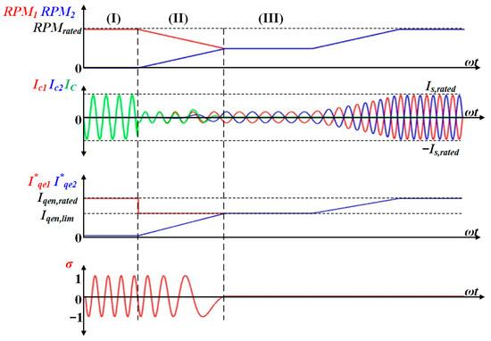
Figure 6.
The proposed operation sequence for accelerating an IM2 while the IM1 is running.
- (I)
- Restriction of the current step: Upon receiving a start command for IM2, I*qe1 and I*qe2 are limited to I*qe1,lim and I*qe2,lim, respectively. This limitation ensures that IC does not exceed the switch current rating.
- (II)
- Speed convergence step: Under the limited torque by I*qen,lim, IM2 accelerates and IM1 decelerates at the same RPM gradient. RPMs converge at a specific RPM defined by the limited torque. The RPMs become equal, allowing the angle controller to be enabled.
- (III)
- Angle controller activation step: If σ is significantly distant from zero at the moment of the angle controller activation, the angle controller may generate a large I*qen in an attempt to force it to zero instantly. This can cause a sudden deceleration or acceleration of RPM. To prevent this sudden surge, σ must be adjusted sufficiently close to zero before the angle controller activation. Therefore, a slight deviation is applied between I*qe1 and I*qe2. Specifically, a small offset magnitude (∆Iqen), which is empirically determined to be approximately 1% to 3% of the rated q-axis current (Iqen,rated), is temporarily added to I*qe2 as shown in Figure 7. This range is sufficiently large to induce a phase alignment, yet small enough to prevent sudden acceleration or deceleration during the transition. Consequently, δ is gradually shifted by 180°, ensuring a smooth transition. Once the speeds match and σ crosses zero (within a tolerance of ±0.02), the angle controller is activated. The Iden,comp generated by the angle controller is applied after ∆Iqen returns to zero. Furthermore, since the variation of σ is very slow during this state, it can be treated as a DC component, making the PI control applicable for stable control [7]. At this point, I*qe2 returns to I*qe2,lim, and δ is fixed at 180°. The current limit is released to Iqen,rated, and I*qen ramps up to Iqen,rated. Consequently, both IMs reach RPMrated synchronously without overcurrent.
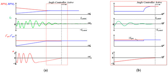 Figure 7. The method for smoothly operating the angle controller in step II: (a) overall waveform (b) expanded waveform.
A similar operation sequence is applied for the transition from dual to single operation as shown in Figure 8, where IM1 is decelerating while IM2 is running.
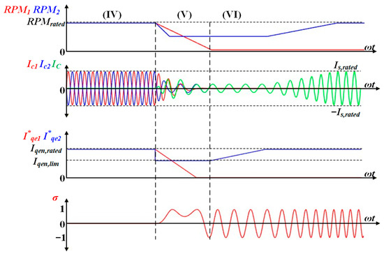
Figure 8.
The proposed operation sequence for decelerating an IM1 while the IM2 is running.
- (IV)
- Angle controller deactivation: Upon receiving a stop command for IM1, the angle controller is deactivated to allow independent control of each motor.
- (V)
- Restriction of the current step: I*qe,1 is controlled to zero to stop and I*qe2 is temporarily limited to I*qe2,lim. Here, IM1 decelerates at twice the speed gradient of IM2. These prevent overcurrent when RPM differences occur.
- (VI)
- Safe shutdown: IM1 continues to decelerate to a standstill, and then I*qe2 returns to Iqe2,rated. Therefore, IM2 is accelerated to RPMrated.
This operation sequence ensures that the C-leg is protected against overcurrent throughout the entire operation state, regardless of load conditions.
4. Switch Fault Diagnosis and Mitigation Methods for FLI
Figure 9 shows the current path depending on the fault switch location in the A-leg. When an open fault occurs in the upper switch (S1), negative current flows through the upper reverse diode (D1) and the lower switch (S2). On the other hand, positive current cannot flow through S1 and flows only through the lower reverse diode (D2). Conversely, when an open fault occurs in S2, positive current flows through S1 and D2, while negative current cannot flow through S2 and flows only through D1. Therefore, the output voltage and current are different from normal conditions. This means that the Isn decreases by fault, enabling fault diagnosis. The Isn is expressed as the stationary reference frame d-q axis current (Idsn, Iqsn, n = 1, 2).
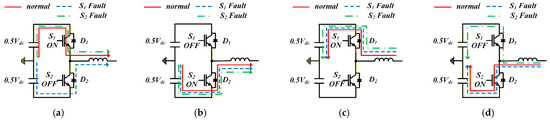
Figure 9.
Current path depending on the fault switch location: (a) I > 0, S1: ON, S2: OFF; (b) I > 0, S1: OFF, S2: ON; (c) I < 0, S1: ON, S2: OFF; (d) I < 0, S1: OFF, S2: ON.
When open-circuit fault occurs, Isn decreases compared to the reference stator current (I*sn). Therefore, the fault is diagnosed as follows.
where fFDn is the fault diagnosis function, and k is a fault diagnosis coefficient with a value between 0 and 1. k is determined by hardware conditions and applications.
Figure 10 shows Ia1, Ib1, Ic1, Is1, and I*s1 when the upper switch of the A-leg is faulty. For simplicity, it is assumed that the two IMs have identical torque and speed conditions. When the upper switch of the A-leg is faulty, no positive current path exists, and thus |Ia1| becomes zero. As a result, Is1 decreases and a fault is diagnosed when Is1 falls below k∙I*s1. In this case, Ia2, Ib2, and Ic2 are not affected. This is because each IM is driven independently by DZS.
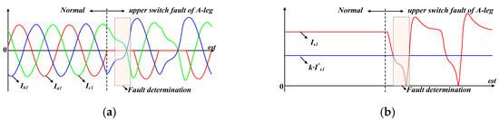
Figure 10.
Waveforms for upper switch fault of A-leg: (a) waveforms of Ia1, Ib1, Ic1; (b) waveforms of Is1, k∙I*s1.
The switch fault of the C-leg can be divided into two cases as shown in Figure 11: when δ = 0° and when δ = 180°. When δ = 0°, as shown in Figure 11a, no positive current path exists. Since the C-phase is shared by both IMs, the fault affects both. Thus, the fault diagnosis is possible on both sides using (5). When δ = 180°, as shown in Figure 11b, no positive current path exists either. However, since IC is almost 0, the current distortion of Ic1 and Ic2 is minimized. In other words, the magnitude of Isn does not decrease significantly; therefore, the fault cannot be easily diagnosed. In this specific condition, the switch fault of the C-leg has no impact on the system because there is no current flow to be interrupted. Consequently, although the open switch fault is not diagnosed, the system continues to operate normally without any performance degradation. When the speed or torque varies, IC becomes non-zero. The fault current path leads to progressive distortion. This distortion naturally enables the fault diagnosis. Therefore, in all other actual scenarios, including different speed, torque, and δ, sufficient distortion occurs to diagnose the fault in the same manner as when δ = 0°.
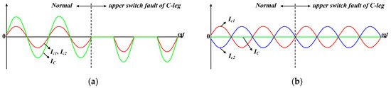
Figure 11.
Waveforms when upper switch fault of C-leg: (a) δ = 0°; (b) δ = 180°.
Figure 12 shows the Isn in the d-q axis reference frame for the fault switch location. Depending on the fault switch location, either the positive or the negative current cannot flow. Except for the case where δ = 180° and a fault switch of the C-leg occurs, Isn appears in a semicircular pattern depending on the fault location (fLn, n = 1, 2). Therefore, the fault switch location can be identified using the θ*n and the phase current magnitude. θ*n can be calculated using I*den and I*qen.
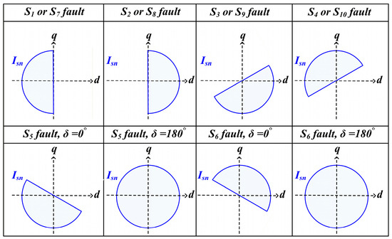
Figure 12.
The Isn in the d-q axis reference frame for the fault switch location.
The location is determined when the phase current corresponding to θ*n is 0. However, a sensing error by the hardware may occur. The phase current magnitude at fLn may not be sensed as exactly 0. Therefore, fLn is determined when the magnitude of the phase current is smaller than k2. k2 is the fault location coefficient, which is determined by hardware conditions and expressed as
In the FLI, an open-circuit fault can cause overcurrent, as shown in Figure 11a. This overcurrent can damage the hardware and the IMs. Therefore, this paper proposes a fault mitigation that prevents overcurrent and stops the IM. If an open-circuit fault occurs in one of the A-leg, B-leg, D-leg, and E-leg, it primarily affects the operation of the motor connected to the fault switch (IMf). Therefore, the fault mitigation method focuses on stopping IMf while simultaneously limiting the current of the motor connected to normal switches (IMn) to prevent the overcurrent. The principle of limitation is similar to the method described in Section 3. The q-axis reference current limit for open-circuit fault (I*fn,lim) is the same value as in (3), and then expressed as
The q-axis reference current of IMf (I*fqen) is regulated to zero to stop this motor. The desired current does not flow by the open-circuit fault, so the angle controller does not operate. Simultaneously, q-axis reference current of IMn (I*nqen) is constrained not to exceed that in (8). Consequently, IMf is safely stopped, while IMn has its current limit restored to Iqen,rated and continues operating.
If a switch of the C-leg has an open-circuit fault, the fault affects both IMs because of the shared current path. Unlike a fault in an independent leg, it is essential to note that normal operation cannot fundamentally be achieved without additional redundant circuits (e.g., isolation relays or additional legs) [22,23]. Therefore, only an immediate system shutdown occurs. When fLn latches at 5 or 6, both IMs are stopped by simultaneously setting I*qe1 and I*qe2 to zero. Figure 13 shows the flowchart described above for when fL,n has a non-zero value.
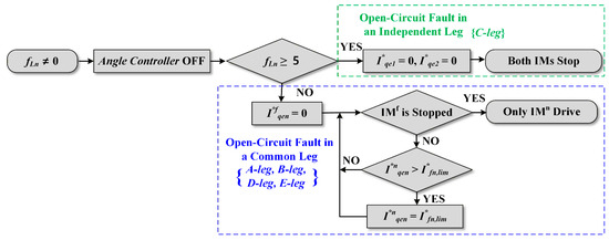
Figure 13.
Flowchart of the fault mitigation when fLn has a non-zero value.
Figure 14 shows the entire block diagram for the proposed system with the operation sequence and the fault diagnosis, where EAC, EIM1, and EIM2 are enable signals for the angle controller and drive command. When EIM1 or EIM2 is latched to 1 (ON), it operates up to RPMrated. If both IMs are operated together, EAC is latched to 1. Conversely, if operated separately or at different speeds, EAC is latched to 0 (OFF). Accordingly, the currents are limited and the angle controller is activated when the speeds become equal. Fault diagnosis is always performed throughout the entire operation. Idsn and Iqsn are calculated from three-phase currents and used to diagnose an open-circuit fault as in (5). When fFDn is latched, I*dsn and I*qsn are used to locate the open-circuit as in (7). Then I*qen is regulated to I*fn,lim according to fLn, as shown in Figure 15.
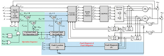
Figure 14.
Entire block diagram for proposed system with the fault diagnosis.
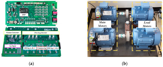
Figure 15.
Experimental setup: (a) prototype of the Vienna rectifier and FLI; (b) induction motors.
5. Experimental Results
The experiments have been implemented to verify the performance of the proposed system. To provide a stable Vdc supply, the PFC employed a Vienna rectifier. Figure 15 shows the experimental setup of the system and Table 1 shows the parameters of the system and IMs used for control. Both IMs have the same parameters. The IM was coupled to a servo motor that created variable load torque and speed conditions. The proposed system was implemented with the TMS320F28377D made by TI. The loads operated as fan loads proportional to the square of the speed.

Table 1.
Experimental parameters.
Figure 16 shows waveforms of line-to-line voltage VUV, IU, Vdc, RPM1, RPM2, Ic1, Ic2, and IC for identical operation. The Vdc is charged to approximately 538 V through a diode rectifier at the start. At point I, both IMs are magnetized before the IM drive. Subsequently, IMs are driven at 450 rpm. During the drive, the Vienna rectifier operates to control Vdc to 650 V at point III. When the angle controller is activated at IV, the IC is controlled to its minimum.
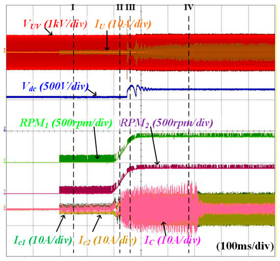
Figure 16.
Waveforms of VUV, IU, Vdc, RPM1, RPM2, Ic1, Ic2, and IC for identical operation.
Figure 17 shows waveforms of RPM1, RPM2, Ic1, Ic2, and IC when applying the conventional current-limiting method. Each current is limited to Isn,rated of 7.7 Apeak. While IM1 operates at 450 rpm, IM2 accelerated from 0 rpm to 450 rpm. Although the current flowing in each IM did not reach the limit, an overcurrent occurred in IC, increasing to a maximum of 14 Apeak.
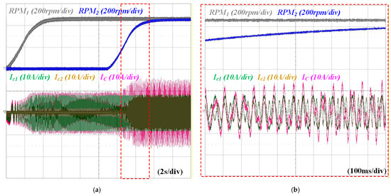
Figure 17.
Waveforms of RPM1, RPM2, Ic1, Ic2, and IC when applying conventional current-limiting method: (a) overall waveforms, (b) expanded waveforms.
Figure 18 shows waveforms of VUV, IU, Vdc, RPM1, RPM2, Ic1, Ic2, and IC for distinct operation. First, when IM1 is started from 0 rpm to 450 rpm, the Vienna rectifier operates. Since IM2 is magnetized before driving, the average value of IC increases by Ic1 as shown in Figure 18b. When IM2 is started, I*qe1 is limited by (3), which decelerates its speed accordingly. The angle controller activates when the speed difference between both IMs is zero. Consequently, as shown in Figure 18c, Ic1 and Ic2 have a phase difference of 180°. Both IMs then accelerate together to 450 rpm while maintaining δ = 180°, as shown in Figure 18d, and the current magnitude increases accordingly. The same sequence applies when IM1 stops during IM2 operation. During this sequence, IC increased only up to the rated current of 7.7 A maximum.
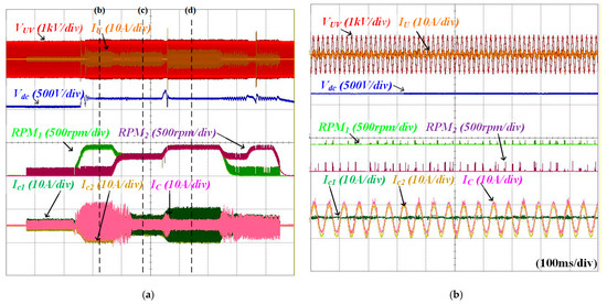
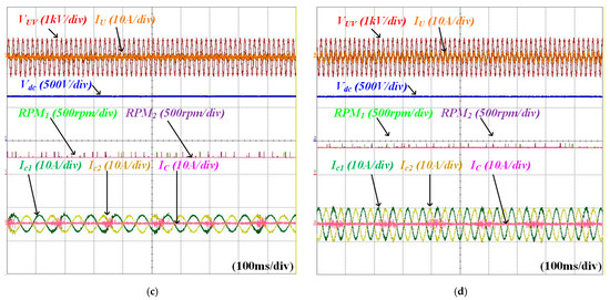
Figure 18.
Waveforms of VUV, IU, Vdc, RPM1, RPM2, Ic1, Ic2, and IC for distinct operation: (a) overall waveforms, (b) only IM1 is operating, (c) angle controller is activated when both IMs are operating, (d) both IMs are operating at 450 rpm.
Figure 19 shows waveforms of IA, IB, IC, ID, IE, Is1, I*s1, θ1, and fL1 according to the fault switch and δ. k and k2 were set to 0.5 and 0.1 for fault diagnosis. Figure 19a and Figure 19b show an open fault in the S1 at δ = 180° and δ = 0°, respectively. The fault is diagnosed when Is1 falls below k∙I*s1. The fault location can be determined by (7). Since fL1 = 1, the fault in S1 is recognized. Figure 19c and Figure 19d show an open fault in S5 at δ = 180° and δ = 0°, respectively. As shown in Figure 19c, when IC is minimum, Is1 does not fall below k∙I*s1. Therefore, the fault is not diagnosed. Conversely, in Figure 19d, the fault can be diagnosed, and fL1 = 5 indicates that S5 is the fault. Consequently, except for the Figure 19c, all faults are diagnosed within half a cycle.
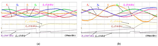
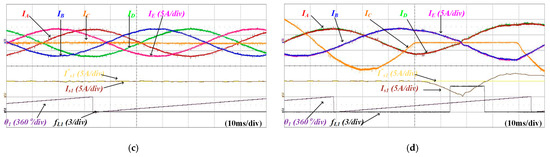
Figure 19.
Waveforms of IA, IB, IC, ID, IE, Is1, I*s1, θ1, fL1 according to the fault switch and δ: (a) open fault in S1 at δ is 180°, (b) open fault in S1 at δ is 0°, (c) open fault in S5 at δ is 180°, (d) open fault in S5 at δ is 0°.
Figure 20 shows waveforms of current under an open-circuit fault in the upper switch of C-leg when a torque difference is 0.1 Nm. The coefficients were set k = 0.9, k2 = 0.1. Since torque difference makes IC to be non-zero, unlike in Figure 19c. As a results, the fault is successfully diagnosed within half of a cycle.
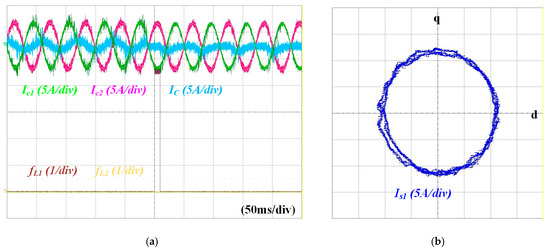
Figure 20.
Waveforms of current under an open-circuit fault in the upper switch of C-leg when a torque difference is 0.1 Nm: (a) Ic1, Ic2, IC, fL1, and fL2, (b) Is1 in the stationary reference frame.
Figure 21 shows waveforms of IA, IB, IC, ID, IE, RPM1, RPM2, fL1, and fL2 for the fault mitigation method when S1 is fault. Both IMs are operating at 500 rpm. When S1 is the fault, the fault is diagnosed by (5)–(7), and the angle controller is not activated. IM1 is controlled to 0 rpm, while IM2 decelerates to a speed by (8). After IM1 is stopped, IM2 can be accelerated to 500 rpm. This operation sequence prevents overcurrent during an open-circuit fault as shown in Figure 21.
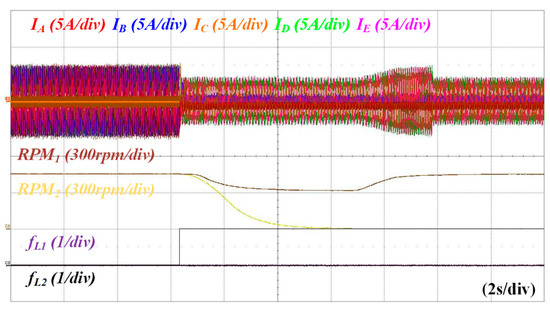
Figure 21.
Waveforms of IA, IB, IC, ID, IE, RPM1, RPM2, fL1, and fL1 for fault mitigation method when S1 is fault.
6. Conclusions
This paper proposes a reliable control strategy for dual induction motor (IM) drives using a five-leg inverter (FLI). The structure of the FLI may cause overcurrent in the common leg when the two IMs operate asynchronously at different speeds. To prevent this overcurrent, an operation sequence that effectively utilizes current limitation and angle controller activation is applied. Furthermore, a fault diagnosis and mitigation method is proposed, ensuring safe shutdown without overcurrent during open-circuit fault conditions. As a result, the proposed strategy ensures reliable system operation under various operating conditions. The experimental results demonstrate that while the common leg current reached a peak of 14 A (180% of the rated current) using conventional methods, the proposed sequence-based current limitation successfully restricted it to 7.7 A (100% of the rated current), ensuring device safety during speed transitions. Furthermore, the fault diagnosis and mitigation method successfully detected open-circuit faults within half a fundamental cycle and enabled safe shutdown without overcurrent. The validity of the proposed system is verified using dual 2.2 kW IMs.
Author Contributions
Conceptualization, J.-S.L.; Methodology, E.L.; Software, E.L.; Validation, E.L. and J.L.; Resources, E.L. and J.L.; Data curation, E.L. and J.L.; Writing—original draft, E.L.; Writing—review & editing, J.-S.L.; Supervision, J.-S.L.; Project administration, J.-S.L.; Funding acquisition, J.-S.L. All authors have read and agreed to the published version of the manuscript.
Funding
The present research was supported by the [research fund of Dankook University in 2025].
Institutional Review Board Statement
Not applicable.
Informed Consent Statement
Not applicable.
Data Availability Statement
The original contributions presented in this study are included in the article. Further inquiries can be directed to the corresponding author.
Conflicts of Interest
The authors declare no conflict of interest.
References
- Talib, M.H.N.; Ibrahim, Z.; Abdul Rahim, N.; Abu Hasim, A.S. Analysis on speed characteristics of Five Leg Inverter for different carrier based PWM scheme. In Proceedings of the 2012 IEEE International Power Engineering and Optimization Conference, Melaka, Malaysia, 6–7 June 2012; pp. 96–101. [Google Scholar]
- Talib, M.H.N.; Ibrahim, Z.; Rahim, N.A.; Hasim, A.S.A. Characteristic of Induction Motor Drives Fed by Three Leg and Five Leg Inverters. J. Power Electron. 2013, 13, 806–813. [Google Scholar] [CrossRef]
- Wang, W.; Zhang, J.; Cheng, M. A Dual-Level Hysteresis Current Control for One Five-Leg VSI to Control Two PMSMs. IEEE Trans. Power Electron. 2017, 32, 804–814. [Google Scholar] [CrossRef]
- Wang, W.; Zhang, J.; Cheng, M.; Cao, R. Direct Torque Control of Five-leg Dual-PMSM Drive Systems for Fault-tolerant Purposes. J. Power Electron. 2017, 17, 161–171. [Google Scholar] [CrossRef]
- Jones, M.; Vukosavic, S.N.; Dujic, D.; Levi, E.; Wright, P. Five-leg inverter PWM technique for reduced switch count two-motor constant power applications. IET Electr. Power Appl. 2008, 2, 275–287. [Google Scholar] [CrossRef]
- Wang, B.; Hu, J.; Hua, W.; Cheng, M.; Wang, G.; Fu, W. Multiple 3-Phase PMA-SynRM With Delta Windings for Enhanced Fault Tolerance. IEEE Trans. Ind. Electron. 2023, 70, 1094–1104. [Google Scholar] [CrossRef]
- Lim, Y.-S.; Lee, J.-S.; Lee, K.-B. Advanced Speed Control for a Five-Leg Inverter Driving a Dual-Induction Motor System. IEEE Trans. Ind. Electron. 2019, 66, 707–716. [Google Scholar] [CrossRef]
- Errabelli, R.R.; Mutschler, P. Fault-Tolerant Voltage Source Inverter for Permanent Magnet Drives. IEEE Trans. Power Electron. 2012, 27, 500–508. [Google Scholar] [CrossRef]
- Zhang, Z.; Hu, Y.; Luo, G.; Gong, C.; Liu, X.; Chen, S. An Embedded Fault-Tolerant Control Method for Single Open-Switch Faults in Standard PMSM Drives. IEEE Trans. Power Electron. 2022, 37, 8476–8487. [Google Scholar] [CrossRef]
- Kolar, J.W.; Friedli, T. The Essence of Three-Phase PFC Rectifier Systems—Part I. IEEE Trans. Power Electron. 2013, 28, 176–198. [Google Scholar] [CrossRef]
- Lee, J.-Y.; Lee, J.-S. An Improved Zero-Current Distortion Compensation Method for the Soft-Start of the Vienna Rectifier. Electronics 2024, 13, 1806. [Google Scholar] [CrossRef]
- Friedli, T.; Hartmann, M.; Kolar, J.W. The Essence of Three-Phase PFC Rectifier Systems—Part II. IEEE Trans. Power Electron. 2014, 29, 543–560. [Google Scholar] [CrossRef]
- Wang, W.; Liu, Y.; Chen, Y.; Liu, C. Optimization-Based Duty Cycle Allocation for a Five-Leg Inverter to Drive Two Electric Motors. IEEE Trans. Power Electron. 2023, 38, 11327–11337. [Google Scholar] [CrossRef]
- Choi, D.; Lee, J.-S.; Lim, Y.-S.; Lee, K.-B. Priority-Based Model Predictive Control Method for Driving Dual Induction Motors Fed by Five-Leg Inverter. IEEE Trans. Power Electron. 2023, 38, 887–900. [Google Scholar] [CrossRef]
- Chen, Y.; Liu, C.; Liu, S.; Liu, Y. Predictive Control Scheme With Adaptive Overmodulation for a Five-Leg VSI Driving Dual PMSMs. IEEE Trans. Ind. Electron. 2024, 71, 71–81. [Google Scholar] [CrossRef]
- Geng, Q.; Peng, Y.; He, J.; Zhou, Z.; Zhang, G. Sensorless Control Method for Dual Permanent Magnet Synchronous Motors Driven by Five-Leg Voltage Source Inverter With Single Current Sensor. IEEE Trans. Power Electron. 2024, 39, 7834–7847. [Google Scholar] [CrossRef]
- Lee, J.Y.; Lee, E.W.; Choi, D.; Lee, J.-S. Low-Complexity Model Predictive Control Method for Driving Dual Induction Motors Fed by Five-leg Inverter. In Proceedings of the 2025 IEEE Applied Power Electronics Conference and Exposition (APEC), Atlanta, GA, USA, 16–20 March 2025; pp. 2311–2316. [Google Scholar]
- Zhang, X.; Shang, Z.; Gao, S.; Zhao, S.; Chen, C.; Wang, K. Open-Circuit Fault Diagnosis for T-Type Three-Level Inverter via Improved Adaptive Threshold Sliding Mode Observer. Appl. Sci. 2025, 15, 6063. [Google Scholar] [CrossRef]
- Wang, W.; Tian, W.; Lu, Z.; Wang, Z.; Hua, W.; Cheng, M. Fault-Tolerant Predictive Control for Five-Leg Dual-Mover Permanent-Magnet Motor Drives. IEEE Trans. Power Electron. 2023, 38, 5803–5815. [Google Scholar] [CrossRef]
- Kwak, Y.-G.; Heo, D.-H.; Kim, S.-P.; Song, S.-G.; Park, S.-J.; Kang, F.-S. Reliability and Economic Efficiency Analysis of 4-Leg Inverter Compared with 3-Leg Inverters. Electronics 2021, 10, 87. [Google Scholar] [CrossRef]
- Kim, S.H. Electric Motor Control: DC, AC, BLDC Motors; Bokdoo: Seoul, Republic of Korea, 2024. [Google Scholar]
- Cordeiro, A.; Palma, J.C.P.; Maia, J.; Resende, M.J. Detection and Diagnosis Solutions for Fault-Tolerant VSI. J. Power Electron. 2014, 14, 1272–1280. [Google Scholar] [CrossRef]
- Jiang, X.; Li, Q.; Huang, W.; Cao, R. A Dual-Winding Fault-Tolerant Motor Drive System Based on the Redundancy Bridge Arm. IEEE Trans. Ind. Electron. 2019, 66, 654–662. [Google Scholar] [CrossRef]
Disclaimer/Publisher’s Note: The statements, opinions and data contained in all publications are solely those of the individual author(s) and contributor(s) and not of MDPI and/or the editor(s). MDPI and/or the editor(s) disclaim responsibility for any injury to people or property resulting from any ideas, methods, instructions or products referred to in the content. |
© 2026 by the authors. Licensee MDPI, Basel, Switzerland. This article is an open access article distributed under the terms and conditions of the Creative Commons Attribution (CC BY) license.