Abstract
Foam-assisted steam flooding is a promising technique to alleviate gas channeling and enhance sweep efficiency in heterogeneous heavy-oil reservoirs. However, long-term foam stabilization remains problematic at high temperatures. Three-phase foam (TPF), containing dispersed solid particles, has been proposed to improve foam stability under harsh reservoir conditions. We fabricated a novel TPF system by adding ultrafine fly ash particles, as well as high-temperature resistant microspheres with an adhesive coating layer. This work aims at assessing the ability of the generated TPF in controlling steam channeling and enhancing oil recovery. Static and core flood tests were performed to evaluate foam strength and stability. Our results suggested a stronger foamability at a lower consolidation agent concentration, while a longer half-life period of foam and settling time of solid particles at a larger consolidation agent concentration were observed. Bubbles suspended independently in the liquid phase, with sizes varying from 10 to 100 μm, smaller than that of the conventional foam, suggesting a significant enhancement of foam dispersity and stability. The plugging rate was close to 90% when the temperature was as high as 300 °C, demonstrating a well-accepted plugging effect under high temperatures. A larger pore volume injection of TPF yielded a higher EOR in parallel cores, which substantiated the effectiveness of the three-phase foam system in sealing high-permeability channels.
1. Introduction
Steam injection has been acknowledged as one of the most effective approaches for heavy-oil exploitation [1,2,3]. Nevertheless, due to the great density disparity, steam tends to flow in the upper reservoir (the so-called “gravity override”), which aggravates as the reservoir thickness increases [4,5]. Moreover, steam viscosity is much lower than that of the reservoir fluids, resulting in severe viscous fingering [6,7]. Steam channeling also emerges in heterogeneous reservoirs [8]. The abovementioned weaknesses lead to significant steam loss and low sweep efficiency.
Foam, marked by low density, small filtration loss and strong particle-carrying ability, preferentially enter high-permeability regions, block large pores or channels, and reduce the permeability of high-permeable layers [9,10,11]. Foam has been widely used to assist steam flooding in heavy-oil exploitation, enabling us to decrease vapor mobility, enlarge the swept volume and enhance oil recovery [12,13]. However, long-term foam stabilization remains challenging at high temperatures [14,15], concerning the effectiveness of profile control treatment by foam when injecting steam into heavy-oil reservoirs.
Solid particles, such as polymers and nanoparticles, have been commonly applied to enhance foam stability [16,17]. Dispersing solid particles into the conventional foam yields the so-called three-phase foam (TPF) system [18]. The resultant high dispersity of bubbles and anomalous foam structure give rise to excellent foam stability, resulting in increased flow resistance, improved plugging efficiency and an extended swept volume [16,18].
Polymers are capable of generating a viscoelastic shell on the water-gas interface, which could mitigate liquid drainage between bubbles and hinder foam collapse, thereby improving foam stability [19,20,21]. Nevertheless, polymer-enhanced foam exhibits poor stability at reservoir conditions when contacting resident brines, crude oils, or minerals in porous media due to faster collapse of the thin liquid films at the gas-liquid interface [22,23]. Moreover, polymers may lose their viscosity-enhancing properties at a high-temperature and high-salinity condition [24]. Polymer concentrations can also increase by up to 10 to 15 times of their original value in formation water, causing pore blocking and the consequent formation damage [25]. Therefore, polymers might not be an appropriate candidate as the foam stabilizer in hydrocarbon reservoirs due to their short-term effectiveness and potential damage to a formation.
Hydrophilic nanoparticles can strongly adsorb onto the interface at harsh reservoir conditions and behave like surfactant molecules. The generated three-dimensional network structure allows slowing down thin liquid film drainage and improving foam stability [26,27]. In contrast, non-adsorbed nanoparticles in the intervening thin film could separate the dispersed phases [16,28]. It has been well documented that the synergetic effect of surfactant and certain types of nanoparticles is able to generate stronger foams and enhance foam stability against shrinkage and coalescence [29,30,31]. However, the aggregation of nanoparticles necessitates special chemical treatment in terms of their surface wettability, making them less cost-effective. As a result, using solid particles from widely available and commercially viable raw materials confers a distinguished economic superiority on particle-stabilized foam for enhanced oil recovery.
Fly ash is a coproduct of coal-fired power plants, serving as a source for the commercial foam stabilizers [32]. Using the abundantly available fly ash to generate the fly ash three-phase foam (FATPF) can significantly reduce the expense of the sealing system and lower the discharge of fly ash that could lead to waste pollution [33]. Lee et al. [34] acquired stable and dense CO2 foam by adding fly ash nanoparticles (referred to “nanoash”) combined with additives. Eftekhari et al. [35] demonstrated that nanoash could be utilized to stabilize nitrogen foam in the presence of crude oil at high temperatures and pressures. Guo et al. [36,37] showed that combining fly ash nanoparticles with a surfactant mixture of alpha-olefin sulfonate and lauramidopropyl betaine results in excellent foamability and stability and highly enhanced oil recovery in microfluidics. Singh et al. [38] generated nanoash-stabilized CO2 foam for CO2 mobility control in sandstone cores and sand packs. Their results suggested that the nanoash produced by the ball-milling method can greatly improve foam stability and the resistance factor. Lv et al. [39] found that the adsorption of fly ash at the CO2-liquid interface may lead to a solid-like bubble film, and the viscosity of FATPF was thrice that of the pure surfactant foam. They further examined the micro-flow behavior and oil-displacement efficiency of the generated FATPF [40]. Given its practicability, fly ash is selected as the foam booster in our formula.
In addition to fly-ash particles, we developed a special micro-sized plugging material (MCL) that comprises a rigid internal core and an adhesive coating layer, which combines the merits of both organic and inorganic particles, including good injectivity, selective plugging, and high plugging intensity. The internal core is made of ultralight ceramsite, and the hot-molten adhesive layer coating out of the inner core is composed of cardanol-modified thermo-setting phenolic resin. When reaching a critical softening temperature, the coating layer starts to melt, and the particles tend to bond with each other under the interactions of these adhesive layers. The thickness of the adhesive outer layer is about 1.5 μm. A series of MCL with a broad range of bonding temperatures can be produced by modifying the ratio of cardanol and phenolic resin as well as the reaction temperature [41,42]. These MCL particles have been substantiated to be efficient in plugging high-permeability channels in porous media [43]. By adjusting the mixture ratio of MCL and fly ash, we can obtain TPF of various plugging rates.
In this study, modified starch gel, sodium dodecyl sulfate (SDS), and consolidation agents incorporating fly ash and MCL are used to generate a novel fly ash three-phase foam system assisted by high-temperature resistant MCL particles. Static evaluation tests are carried out to assess the foamability, stability and suspendability of the generated TPF. Single- and parallel-core floods are performed to test the plugging performance and oil-displacement efficiency.
2. Experimental Study
2.1. Materials and Preparation
2.1.1. Microsphere
The microsphere is composed of an internal core and a layer of coating materials (Figure 1). The internal core is made of ultralight ceramsite, with a bulk density between 1.06 g/cm3 and 1.25 g/cm3. A nominal breaking rate of the ceramsite varying from 3.5% to 18% under 52MPa is recorded by the manufacturer (Beijing Qisintal New Material Co., Ltd, Beijing, China). A hot molten layer with a critical softening temperature is made of cardanol modified thermosetting phenolic resin. When the surface temperature reaches a threshold, the exposed adhesive coating layer gradually melts and swells, and particles tend to bond with each other. The average size of MCL used in our experiments is about 100 μm. The critical molten temperature of the adhesive layer is 120 °C.
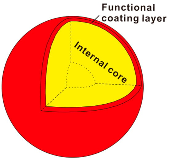
Figure 1.
Schematic of MCL structure: the rigid internal core and the functional coating layer.
2.1.2. Three-Phase Foam
The compositions of the prepared three-phase foam contain sodium dodecyl sulfate (SDS), modified starch gel system, and consolidation agent (including fly ash and MCL, with a mass ratio of 1:4). The modified starch gel is the grafted copolymer of α-starch and acrylamide monomer, which has been successfully used to generate high tensile foam [44,45,46]. Fly ash with an average size smaller than 15 μm is provided by HX oil field company, China. The major components of the fly ash are SiO2 and Al2O3, accounting for over 90 wt.% on the whole.
2.1.3. Quartz Sand
The main component of quartz sands used for core floods is SiO2 (over 99%). Sands are first sieved to assist the reproducibility of core properties. The sand-washing procedures are delineated in [47].
2.1.4. Cores and Fluids
Single-phase plugging tests are performed in sand packs of various permeability ranging from 29 to 10,200 millidarcys (mD), filling with quartz sand of 10–40 mesh. The permeabilities of sand-filled pipes, consistent with the target reservoir in HX oil field, China, can be regulated by changing the mixing ratio of quartz sands with different sizes and the degree of compaction. The diameter and length of the packed column are 2.5 cm and 50 cm, respectively. We use wet-packing procedures for quartz-sand compaction [47]. The porosity varies between 0.28 and 0.45. Oil-displacement tests are carried out in parallel heterogeneous artificial cores of different permeability ratios (defined as the ratio of the high permeability over the low permeability of the two parallel cores). The properties of the sand packs and artificial cores are given in Table 1.

Table 1.
Parameters of parallel heterogeneous sand packs and artificial cores.
Deionized water (Millipore Corporation, Burlington, MA, USA) is degassed and used for the preparation of artificial formation water (AFW) with the same ionic compositions as that in the studied reservoir. The major ionic components of AFW are given in Table 2. The degassed and dehydrated oil from the targeted reservoir in HX oil field is used for oil displacement tests. The oil viscosity is 7699 mPa·s at ambient conditions.

Table 2.
Ionic compositions of AFW.
2.2. Laboratory Setup for Core Floods
A schematic diagram of the laboratory setup is illustrated in Figure 2.
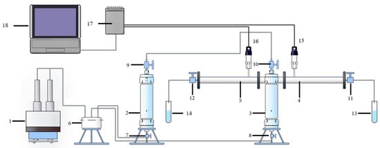
Figure 2.
Experimental setup for core floods: 1—syringe pump, 2—AFW, 3—TPF, 4 and 5—sand packs, 6—six-way valves, 7–12—control valves, 13 and 14—test tubes, 15 and 16—pressure transducers, 17—data acquisition system, 18—PC with LabView.
Syringe pump 1 (100DX, Teledyne ISCO, Lincoln, NE, USA) equipped with two 90-mL stainless steel syringes is used for delivering AFW 2 or TPF 3 to parallel sand packs (or cores) 4 and 5, which allows us to emulate the co-existence of high- and low-permeability channels. A six-port valve 6 and six one-way valves 7–12 are used to connect the apparatus, ensuring continuous fluid injection into the sand pack. Valves 9–12 isolate the two sand packs (or cores) from other parts of the system, enabling one to eliminate fluid leakage during system assembly. Effluent fluids are collected at the outlets by test tubes 13 and 14. The injection pressure is measured by pressure transmitters 15 and 16. The acquired data are transmitted to the data collection system 17 and 18.
2.3. Methodology
2.3.1. Static Evaluation Tests
Foamability and Foam Stability
Foamability and stability are two essential indicators to assess the foam performance. Our foam system is fabricated following the Waring Blender method. A volume of 100 mL of solution containing the α-starch, methylene-bisacrylamide, potassium peroxodisulfate and sodium sulfite is first placed in a thermal chamber set at 80 °C. The solution viscosity is regularly recorded until it is gelatinized. Then, 100 mL of the prepared 80 °C dispersion containing lauryl sodium sulfate and consolidation agent is well mixed with the gelatinized starch gel system. The materials used for foam generation and their mass concentrations are shown in Table 3. It is followed by pouring the obtained mixture into a Warning blender and stirring for three minutes at 8000 rpm. The generated foam is then transferred into a 1000 mL measuring cylinder, and the initial volume of the foam is immediately recorded to evaluate the foaming capability. The measuring cylinder is placed into the thermal chamber to observe foam stability at 80 °C. When 50 mL solution is observed, the corresponding duration is regarded as the half-life period of the foam. The observation lasts for one week. Five tests are conducted to study the influence of consolidation agent concentrations (0.5%, 5%, 10%, 20% and 30%) on foaming capability and stability.

Table 3.
List of experiments.
Suspendability Tests
The addition of MCL particles in the consolidation agent necessitates a good particle-carrying ability of the foam, so that the MCL can transport deeper in porous media and block high-permeability channels to achieve profile control. The prepared consolidation agents of various mass concentrations (0.5%, 5%, 10%, 20% and 30%) are well mixed with the generated foam. The obtained mixture stands in a measuring cylinder until approximately 10% of the MCL particles settle at the bottom. The sedimentation period is recorded to assess the foam’s particle-carrying capability.
2.3.2. Single-Phase Plugging Tests
Thermal Stability
Dynamic foam stability under a high temperature signifies the transport and plugging properties of foam in hydrocarbon reservoirs. Therefore, core floods in the absence of oil are carried out at three temperatures to assess the dynamic thermal stability. Sand packs are first vacuumed and saturated with AFW, followed by injection of 0.3 PV starch-gel three-phase foam system containing 5% consolidation agent at a flow rate of 0.5 mL/min. The sand packs are then placed in a thermal chamber (80 °C, 150 °C, and 300 °C) for 24 h. In the last stage, the subsequent water is injected at 0.5 mL/min until the pressure reaches a plateau. The variation of injection pressure is regularly documented. The physical properties of the sand packs (SPS-1, SPS-2, and SPS-3) are given in rows 2–4, Table 1.
Permeability Influence
Permeability can significantly affect foam’s plugging performance as it directly relates to the pore size distribution of porous media. Sand packs (SPS-4 and SPS-5) of permeabilities 5830 mD and 8939 mD are used to investigate permeability effect on the plugging performance of the generated three-phase foam. Following the procedure presented in 2.3.2.1, 0.3 PV starch-gel three-phase foam containing 5% consolidation agent is injected into the AFW saturated sand packs at a flow rate of 0.5 mL/min. The sand packs are then placed in a thermal chamber set at 80 °C for 24 h. The subsequent water is then injected with the same flow rate until the pressure is stable. The variation of injection pressure is regularly recorded.
Influences of Permeability Ratio
Heterogeneity is a critical factor that causes water/gas channeling during fluid injection. Permeability ratio is considered an indicator of the extent of reservoir heterogeneity. As a result, parallel heterogeneous sand packs with various permeability ratios (5520/30 and 10,200/30) are applied to study the influence of permeability ratio on foam plugging performance. Water is first injected into parallel cores at a flow rate of 0.5 mL/min until the fractional flow in each core becomes stable. It is followed by injecting 0.3 PV starch-gel three-phase foam. The mass concentration of the consolidation agent maintains the same as in previous tests, i.e., 5%. When foam injection terminates, the experimental system stands for 24 h to make the foam gelated. The subsequent water is then injected until the pressure reaches a steady state. The flow rate remains the same throughout the whole test. The fractional flow rates (defined as the ratio of the flow rate in each of the parallel cores over the total flow rate) are recorded.
The profile control efficiency is characterized by the profile improvement rate η, expressed by [48]
where Qha and Qla are the flow rates in the high-permeability core and low-permeability core after foam injection, respectively, mL/min; Qhb and Qlb are the flow rates in the high-permeability core and low-permeability core before foam injection, respectively, mL/min.
After foam injection, the difference between the flow rates in high-permeability and low-permeability cores is narrowed down, yielding a higher profile control efficiency. Apparently, higher η indicates a better profile control efficiency.
2.3.3. Oil Displacement Tests
Parallel heterogeneous artificial cores (AC-1, AC-2, AC-3, and AC-4) of different permeability ratios (5000/1000 and 5000/500) are used for oil displacement tests. The dimension of the artificial cores is 30 cm × 4.5 cm × 4.5 cm. Cores are first vacuumed and saturated with AFW and then saturated with the degassed and dehydrated oil from the targeted reservoir, aging for 24 h. The primary water is injected at a constant flow rate of 0.5 mL/min until the water cut reaches 98%. A certain volume (0.2 PV and 0.3 PV) of three-phase foam is then injected, after which the system stands for 24 h. The subsequent water is injected until the water cut is as high as 98%. Water cut, oil recovery, and injection pressure are documented. Oil volumes produced from both of the parallel cores are counted for oil recovery.
3. Results and Discussion
This section presents the results and discussion on the experimental study described in Section 2. The experimental results of foamability, foam stability and particle-carrying capability are shown in Section 3.1 and Section 3.2. The microstructure of the generated TPF is demonstrated in Section 3.3. Section 3.4 analyzes the influences of temperature, core permeability and permeability ratio on the plugging performance. Section 3.5 demonstrates oil-displacement efficiency.
3.1. Foamability and Foam Stability
Table 4 demonstrates the foaming volume and half-life period of the three-phase foam system containing various consolidation agents.

Table 4.
Three-phase foam properties.
Figure 3 shows the images of foam volume when it is just generated under various consolidation concentrations. It is observed that the foaming volume decreases as the consolidation agent concentration increases, indicating a weaker foamability at a higher consolidation agent concentration. This is ascribed to the less liquid proportion at a higher consolidation agent concentration, given that the base solution maintains the same volume. However, the half-life period of foam is highly increased with an increasing consolidation agent concentration, showing stronger stability. Fluid drainage does not show up when the consolidation agent concentration reaches 20%, and the system becomes solidified.
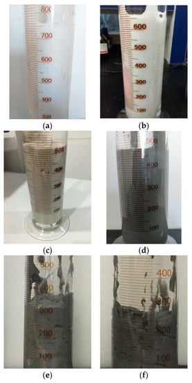
Figure 3.
Images of the generated foam under various consolidation concentrations: (a) 0%; (b) 0.5%; (c) 5%; (d) 10%; (e) 20%; (f) 30%.
3.2. Suspendability
In the three-phase foam system, solid particles are suspended by the gaseous phase and squeezed by bubbles. When the bubbles supporting particles are deformed, particles might settle to the bottom. The consolidation agents used in our study cannot distort the bubbles due to their tiny sizes. As a result, those particles do not move or settle due to the existence of neighboring bubbles. Table 5 shows the influence of consolidation agent concentration on particle settling time. Increasing consolidation agent concentration yields a longer settling time. The three-phase foam system exhibits a splendid particle-carrying capability at all tested consolidation agent concentrations. It is worth noting that MCL settling is not observed in the foam containing 20% and 30% consolidation agents. As seen in Figure 3, the foam system becomes solidified due to the large proportion of solid particles at the consolidation agent concentrations of 20% and 30%. We conclude that consolidation agents ranged within 5% to 10% would be optimal for achieving a balance among foamability, stability, and suspendability. We select 5% as the solid particle concentration in the rest tests to lower the cost.

Table 5.
Three-phase foam properties.
3.3. Foam Microstructure
Foam is a thermodynamically unstable system, and its stability is controlled by the process of liquid film thinning and bubble coalescence. During liquid film thinning, bubbles push against each other, while the total surface area is changeless. In comparison, bubble coalescence results in a larger bubble, leading to a decrease in the total surface area. The coalescence rate of bubbles is determined by the speed of liquid film thinning and rupture. The smaller is the bubble volume, the stronger is the pressure-resistant ability, and the harder is the liquid film rupture.
The fluid loss in a foam system arises from the mutual squeezing of bubbles and the effect of gravity. Bubble squeezing originates from the surface pressure of the so-called “Plateau border”. As seen in Figure 4a, the conventional foam exhibits an unstable hexagonal structure that may lead to fast bubble fluid loss and rupture. However, in comparison, the bubbles of the three-phase foam exist in the liquid phase independently, showing high dispersity and a smaller size ranging from 10 to 100 μm if compared to the conventional foam (Figure 4b). Figure 4b demonstrates typical microstructure of aqueous foam stabilized by solid particles. Analogous figures have been reported in the literature [18,32,40]. The smaller bubble size of the three-phase foam might be attributed to the irreversible adsorption and aggregation of fly ash particles at the liquid-gas interface of the foam and plateau borders. The adsorbed particles can reduce the direct contact between the fluids to mitigate liquid drainage and decrease the rate of film rupture and bubble coarsening [32], thereby improve foam stability. Moreover, although the presence of fly ash particles cannot significantly affect the interfacial tension [27,40], the adsorbed solid particles can notably increase the dilatational interfacial viscoelasticity that characterizes bubbles’ ability to resist external disturbances. At high viscoelasticity, the liquid film shows a solid-like behavior that is favorable to restrain the coalescence and rupture of bubbles [40]. Therefore, due to the protection of adsorbed particles, the tiny bubbles can survive longer than the conventional foam. The coagulation of MCL is anticipated to help the three-phase foam achieve better profile control, enhancing the plugging performance. Furthermore, the starch gel, serving as a suspending agent, increases liquid viscosity due to its reticulated texture and contributes positively to the mechanical strength of the liquid film surrounding a bubble.
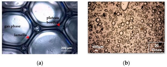
Figure 4.
Images of the conventional foam system and the three-phase foam system: (a) conventional foam (adopted from [49]); (b) three-phase foam (magnified by 20 times).
3.4. Plugging Performance
3.4.1. Temperature Influence
Figure 5 shows the injection pressure of TPF under different temperatures. The injection pressure increases during TPF injection. The higher is the temperature, the weaker is the foam stability, and thus the lower is the injection pressure. When the subsequent water is injected, the injection pressure continues to increase until reaching a maximum value. The maximum value is referred to as the breakthrough pressure, after which the injection pressure drops dramatically due to foam destabilization. The breakthrough pressures are 6.7 MPa, 5.8 MPa, and 1.2 MPa at 80 °C, 150 °C, and 300 °C, respectively. The permeabilities after foam injection are 311 mD, 566 mD, and 309 mD, respectively. The corresponding plugging rates, defined as the ratio of the difference between the permeabilities before and after foam treatment over the initial permeability [50], are 85%, 73%, and 86%, respectively. The high values of plugging rates demonstrate a well-accepted plugging performance under high temperatures.
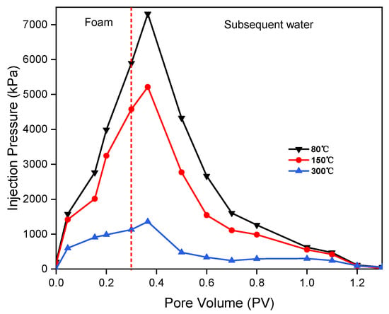
Figure 5.
Influence of temperature on injection pressure.
3.4.2. Permeability Influence
As depicted in Figure 6, after 0.3 PV foam injection, the injection pressures rise to 2.1 MPa and 1.2 MPa for sand packs of permeability 5830 mD and 8939 mD, respectively. After the subsequent water injection, the pressure increases continuously. The corresponding breakthrough pressures are 4.5 MPa and 4.1 MPa for the low-permeability and high-permeability cores, respectively. Core permeabilities decrease to 711 mD and 1155 mD before the occurrence of water breakthrough, yielding corresponding plugging rates of 88% and 87%, respectively. The breakthrough pressure descends as permeability increases, resulting from the increasing pore size and decreasing capillary pressure. When the breakthrough occurs, the pressure shows a sharp decline due to a quick formation of water channeling.
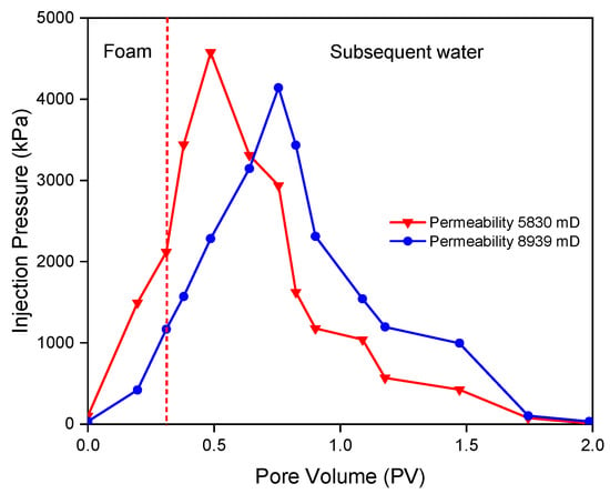
Figure 6.
Influence of permeability on injection pressure.
3.4.3. Influence of Permeability Ratio
As shown in Figure 7, the three-phase foam can remarkably plug the high-permeability channel and achieve satisfactory profile control, while exhibiting indistinctive damage to the low-permeability zone. The profile control efficiencies are about 0.89 and 0.87 for the two tests, respectively. The larger the permeability ratio is, the greater the fractional flow difference is in the parallel heterogeneous sand packs, and the worse the profile control performance is.
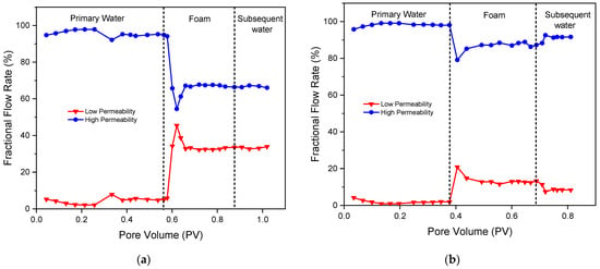
Figure 7.
Influence of permeability ratio on fractional flow rates: (a) permeability ratio 5520/29; (b) permeability ratio 10,200/30.
3.5. Oil-Displacement Efficiency
As depicted in Figure 8 and Figure 9, the oil recovery of parallel cores is improved to a certain extent after foam injection in all the performed experiments, demonstrating effective profile control by the three-phase foam.
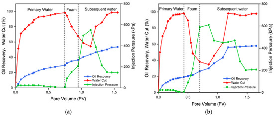
Figure 8.
The influence of the three-phase foam slug size on oil displacement in parallel cores of permeability ratio 5: (a) 0.2 PV; (b) 0.3 PV.
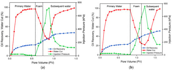
Figure 9.
The influence of the three-phase foam slug size on oil displacement in parallel cores of permeability ratio 10: (a) 0.2 PV; (b) 0.3 PV.
During the primary water flooding, the injection pressure exhibits a slight decline, while the water cut surges. The decrease of the injection pressure and the increase of the water cut arise from the presence of a water breakthrough channel that reduces flow resistance. The oil recoveries after primary water injection into parallel cores of permeability ratio 5 are 29% and 20%, respectively. The difference might be ascribed to the variance of core heterogeneity, which causes different injection periods of the primary water floods. We cease the primary water flooding when the water cut reaches 98%. In comparison, the primary water flooding in parallel cores of permeability ratio 10 yields an oil recovery of 22% for both tests. The lower oil recovery originates from the higher permeability ratio that delivers a larger difference in the fractional flow rate, thereby less oil production in the low-permeability cores.
The notable increase of injection pressure during foam injection arises from the significant foam resistance. As continuously pumped into the parallel cores, the MCL assisted three-phase foam selectively enters the high-permeability zone, plugs the pore throats inside the water breakthrough channel, and thus significantly reduces water cut and expands the swept volume. Due to the growth in flow resistance, the difference between the fractional flow rates of the high- and low-permeability cores narrows down during the injection of the subsequent water. Thus, more oil is recovered from the low-permeable layer. The injection pressure presents a further remarkable growth in the early period of subsequent water injection, manifesting that the three-phase foam remains effective in pore plugging. It is worth mentioning that the injection pressure during the subsequent water flood declines to a level that is a bit higher than the initial injection pressure, which might be caused by the migration of MCL and its ability in profile control.
The enhanced oil recoveries in parallel cores of permeability ratio 5 are about 25% and 30% for 0.2 PV and 0.3 PV foam injection, respectively. In comparison, the enhanced oil recoveries in parallel cores of permeability ratio 10 are about 30% and 36% for 0.2 PV and 0.3 PV foam injection, respectively. As expected, the injection of 0.3 PV foam results in a higher EOR in parallel cores of various permeability ratios due to its better performance in pore blocking. This complies with the fact that 0.2 PV foam injection yields a lower breakthrough pressure than that of 0.3 PV foam injection. Furthermore, a higher permeability ratio leads to higher EOR, which substantiates the effectiveness of the three-phase foam system in sealing high-permeability channels. This conclusion is contradictory to the result presented in Section 3.4.3, where we conclude that a larger permeability ratio gives rise to worse profile control. The contradiction might originate from the wide difference in the permeability ratios of those cores used in our experiments. When the permeability ratio is small, a larger permeability ratio can lead to a more effective redistribution of the fractional flow. Nevertheless, when the permeability ratio is overlarge, the effectiveness of profile control is indistinctive and less fraction of fluid diverts to the low-permeability channels.
4. Conclusions
We present a novel fly ash three-phase foam system assisted by high-temperature resistant microspheres coated with an adhesive layer. This novel foam system allows mitigating gas channeling that occurs during steam injection into heterogeneous heavy-oil reservoirs. Therefore, it is a promising candidate for enhanced oil recovery via profile control. Our study allows drawing the following conclusions.
- (1)
- The foaming volume increases as the consolidation agent concentration decreases, suggesting a stronger foamability at a lower consolidation agent concentration. However, the half-life period of foam is remarkably declined with a descending consolidation agent concentration, showing weaker stability. Fluid drainage does not appear when the consolidation agent concentration reaches 20%. Additionally, increasing consolidation agent concentration yields a longer settling time of solid particles.
- (2)
- The presence of MCL in TPF enables an improvement in plugging performance under high temperature. The plugging rate is close to 90% when the temperature is as high as 300 °C, demonstrating a well-accepted plugging effect. The lower is the permeability, the higher is the breakthrough pressure.
- (3)
- As the permeability ratio increases, a more effective redistribution of the fractional flow is anticipated. Nevertheless, if the permeability ratio is overlarge, the effectiveness of profile control is indistinctive and less fraction of fluid diverts to the low-permeability channels.
- (4)
- A larger pore volume injection of TPF results in a higher EOR in parallel cores, which substantiates the effectiveness of the three-phase foam system in sealing high-permeability channels.
Author Contributions
Conceptualization, J.H.; methodology, Y.Y., T.C. and T.L.; validation, Y.Y. and Z.Y.; formal analysis, Y.Y. and T.C.; investigation, Y.Y. and T.C.; resources, J.H.; data curation, T.C.; writing—original draft preparation, Y.Y.; writing—review and editing, Z.Y.; supervision, J.H.; project administration, J.H.; funding acquisition, Y.Y. and J.H. All authors have read and agreed to the published version of the manuscript.
Funding
Financial supports from the National Natural Science Foundation of China (Grant No. 51804316, Grant No. 41702249, and Grant No. U1762211) and the Science Foundation of China University of Petroleum, Beijing (Grant No. 2462020XKBH013) are greatly acknowledged.
Data Availability Statement
Data is contained within this article.
Conflicts of Interest
The authors declare no conflict of interest.
References
- Li, S.; Li, Z.; Sun, X. Effect of flue gas and n-hexane on heavy oil properties in steam flooding process. Fuel 2017, 187, 84–93. [Google Scholar] [CrossRef]
- Zhao, D.W.; Wang, J.; Gates, I.D. Optimized solvent-aided steam-flooding strategy for recovery of thin heavy oil reservoirs. Fuel 2013, 112, 50–59. [Google Scholar] [CrossRef]
- Brame, S.D.; Li, L.; Mukherjee, B.; Patil, P.D.; Potisek, S.; Nguyen, Q.P. Organic bases as additives for steam-assisted gravity drainage. Pet. Sci. 2019, 16, 1332–1343. [Google Scholar] [CrossRef]
- Pang, Z.; Liu, H.; Zhu, L. A laboratory study of enhancing heavy oil recovery with steam flooding by adding nitrogen foams. J. Pet. Sci. Eng. 2015, 128, 184–193. [Google Scholar] [CrossRef]
- Lyu, X.; Liu, H.; Pang, Z.; Sun, Z. Visualized study of thermochemistry assisted steam flooding to improve oil recovery in heavy oil reservoir with glass micromodels. Fuel 2018, 218, 118–126. [Google Scholar] [CrossRef]
- Wang, Y.; Liu, H.; Pang, Z.; Gao, M. Visualization Study on Plugging Characteristics of Temperature-Resistant Gel during Steam Flooding. Energy Fuels 2016, 30, 6968–6976. [Google Scholar] [CrossRef]
- Norouzi, M.; Dorrani, S.; Shokri, H.; Bég, O.A. Effects of viscous dissipation on miscible thermo-viscous fingering instability in porous media. Int. J. Heat Mass Transf. 2019, 129, 212–223. [Google Scholar] [CrossRef]
- Janssen, M.T.G.; Pilus, R.M.; Zitha, P.L.J. A Comparative Study of Gas Flooding and Foam-Assisted Chemical Flooding in Bentheimer Sandstones. Transp. Porous Media 2019, 131, 101–134. [Google Scholar] [CrossRef]
- Farajzadeh, R.; Andrianov, A.; Krastev, R.; Hirasaki, G.; Rossen, W.R. Foam-Oil Interaction in Porous Media: Implications for Foam Assisted Enhanced Oil Recovery. Adv. Colloid Interfac. 2012, 183, 1–13. [Google Scholar] [CrossRef] [PubMed]
- Hosseini-Nasab, S.M.; Zitha, P.L.J. Investigation of Chemical-Foam Design as a Novel Approach toward Immiscible Foam Flooding for Enhanced Oil Recovery. Energy Fuels 2017, 31, 10525–10534. [Google Scholar] [CrossRef]
- Li, R.F.; Yan, W.; Liu, S.; Hirasaki, G.J.; Miller, C.A. Foam Mobility Control for Surfactant Enhanced Oil Recovery. SPE J. 2010, 15, 928–942. [Google Scholar] [CrossRef]
- Guo, F.; Aryana, S.A. Improved sweep efficiency due to foam flooding in a heterogeneous microfluidic device. J. Petrol. Sci. Eng. 2018, 164, 155–163. [Google Scholar] [CrossRef]
- Liu, P.; Li, W.; Shen, D. Experimental study and pilot test of urea- and urea-and-foam-assisted steam flooding in heavy oil reservoirs. J. Pet. Sci. Eng. 2015, 135, 291–298. [Google Scholar] [CrossRef]
- Oetjen, K.; Bilke-Krause, C.; Madani, M.; Willers, T. Temperature effect on foamability, foam stability, and foam structure of milk. Colloids Surf. A Physicochem. Eng. Asp. 2014, 460, 280–285. [Google Scholar] [CrossRef]
- Wang, H.; Guo, W.; Zheng, C.; Wang, D.; Zhan, H. Effect of Temperature on Foaming Ability and Foam Stability of Typical Surfactants Used for Foaming Agent. J. Surfactants Deterg. 2017, 20, 615–622. [Google Scholar] [CrossRef]
- Zhao, G.; Dai, C.; Wen, D.; Fang, J. Stability mechanism of a novel three-Phase foam by adding dispersed particle gel. Colloids Surf. A Physicochem. Eng. Asp. 2016, 497, 214–224. [Google Scholar] [CrossRef]
- Alargova, R.G.; Warhadpande, D.S.; Paunov, A.V.N.; Velev, O.D. Foam Superstabilization by Polymer Microrods. Langmuir 2004, 20, 10371–10374. [Google Scholar] [CrossRef]
- Wang, T.; Fan, H.; Yang, W.; Meng, Z. Stabilization mechanism of fly ash three-phase foam and its sealing capacity on fractured reservoirs. Fuel 2020, 264, 116832. [Google Scholar] [CrossRef]
- Zhou, W.; Xin, C.; Chen, S.; Yu, Q.; Wang, K. Polymer-Enhanced Foam Flooding for Improving Heavy Oil Recovery in Thin Reservoirs. Energy Fuels 2020, 34, 4116–4128. [Google Scholar] [CrossRef]
- Zhao, G.; Dai, C.; Zhang, Y.; Chen, A.; Yan, Z.; Zhao, M. Enhanced foam stability by adding comb polymer gel for in-depth profile control in high temperature reservoirs. Colloids Surf. A Physicochem. Eng. Asp. 2015, 482, 115–124. [Google Scholar] [CrossRef]
- Zhu, T.; Ogbe, D.O.; Khataniar, S. Improving the Foam Performance for Mobility Control and Improved Sweep Efficiency in Gas Flooding. Ind. Eng. Chem. Res. 2004, 43, 4413–4421. [Google Scholar] [CrossRef]
- Yekeen, N.; Idris, A.K.; Manan, M.A.; Samin, A.M.; Risal, A.R.; Kun, T.X. Bulk and bubble-scale experimental studies of influence of nanoparticles on foam stability. Chin. J. Chem. Eng. 2017, 25, 347–357. [Google Scholar] [CrossRef]
- Kutay, S.; Schramm, L. Structure/Performance Relationships for Surfactant and Polymer Stabilized Foams in Porous Media. J. Can. Pet. Technol. 2004, 43, 19–28. [Google Scholar] [CrossRef]
- Emrani, A.S.; Nasr-El-Din, H.A. Stabilizing CO2 Foam by Use of Nanoparticles. SPE J. 2017, 22, 494–504. [Google Scholar] [CrossRef]
- Xu, X.; Saeedi, A.; Liu, K. An experimental study of combined foam/surfactant polymer (SP) flooding for carbone dioxide-enhanced oil recovery (CO2-EOR). J. Pet. Sci. Eng. 2017, 149, 603–611. [Google Scholar] [CrossRef]
- Risal, A.R.; Manan, M.A.; Yekeen, N.; Azli, N.B.; Samin, A.M.; Tan, X.K. Experimental investigation of enhancement of carbon dioxide foam stability, pore plugging, and oil recovery in the presence of silica nanoparticles. Pet. Sci. 2018, 16, 344–356. [Google Scholar] [CrossRef]
- Alyousef, Z.; Almobarky, M.; Schechter, D. Enhancing the Stability of Foam by the Use of Nanoparticles. Energy Fuels 2017, 31, 10620–10627. [Google Scholar] [CrossRef]
- Dong, X.; Xu, J.; Cao, C.; Sun, D.; Jiang, X. Aqueous foam stabilized by hydrophobically modified silica particles and liquid paraffin droplets. Colloids Surf. A Physicochem. Eng. Asp. 2010, 353, 181–188. [Google Scholar] [CrossRef]
- Binks, B.P.; Kirkland, M.; Rodrigues, J.A. Origin of stabilisation of aqueous foams in nanoparticle-surfactant mixtures. Soft Matter. 2008, 4, 2373–2382. [Google Scholar] [CrossRef]
- Bahraminejad, H.; Manshad, A.K.; Keshavarz, A. Characterization, Micellization Behavior, and Performance of a Novel Surfactant Derived from Gundelia tournefortii Plant during Chemical Enhanced Oil Recovery. Energy Fuels 2021, 35, 1259–1272. [Google Scholar] [CrossRef]
- Singh, R.; Mohanty, K.K. Synergy between Nanoparticles and Surfactants in Stabilizing Foams for Oil Recovery. Energy Fuels 2015, 29, 467–479. [Google Scholar] [CrossRef]
- Yekeen, N.; Manan, M.A.; Idris, A.K.; Padmanabhan, E.; Junin, R.; Samin, A.M.; Gbadamosi, A.O.; Oguamah, I. A comprehensive review of experimental studies of nanoparticles-stabilized foam for enhanced oil recovery. J. Pet. Sci. Eng. 2018, 164, 43–74. [Google Scholar] [CrossRef]
- Phong, G.M.; Pilus, R.M.; Mustaffa, A.; Thangavel, L.; Mohamed, N.M. Relationship between fly ash nanoparticle-stabilized-foam and oil production in core displacement and simulation studies. Fuel 2020, 266, 117033. [Google Scholar] [CrossRef]
- Lee, D.; Cho, H.; Lee, J.; Huh, C.; Mohanty, K. Fly ash nanoparticles as a CO2 foam stabilizer. Powder Technol. 2015, 283, 77–84. [Google Scholar] [CrossRef]
- Eftekhari, A.A.; Krastev, R.; Farajzadeh, R. Foam Stabilized by Fly Ash Nanoparticles for Enhancing Oil Recovery. Ind. Eng. Chem. Res. 2015, 54, 12482–12491. [Google Scholar] [CrossRef]
- Guo, F.; Aryana, S. An experimental investigation of nanoparticle-stabilized CO2 foam used in enhanced oil recovery. Fuel 2016, 186, 430–442. [Google Scholar] [CrossRef]
- Guo, F.; He, J.; Johnson, P.A.; Aryana, S.A. Stabilization of CO2 foam using by-product fly ash and recyclable iron oxide nanoparticles to improve carbon utilization in EOR processes. Sustain. Energy Fuels 2017, 1, 814–822. [Google Scholar] [CrossRef]
- Singh, R.; Gupta, A.; Mohanty, K.K.; Huh, C.; Lee, D.; Cho, H. Fly Ash Nanoparticle-Stabilized CO2-in-Water Foams for Gas Mobility Control Applications. In Proceedings of the SPE Annual Technical Conference and Exhibition, Houston, TX, USA, 28 September 2015; Society of Petroleum Engineers: Houston, TX, USA, 2015. [Google Scholar]
- Lv, Q.; Li, Z.; Li, B.; Husein, M.M.; Li, S.; Shi, D.; Liu, W.; Bai, H.; Sheng, L. Synergistic Mechanism of Particulate Matter (PM) from Coal Combustion and Saponin from Camellia Seed Pomace in Stabilizing CO2 Foam. Energy Fuels 2018, 32, 3733–3742. [Google Scholar] [CrossRef]
- Lv, Q.; Zhou, T.; Zhang, X.; Zuo, B.; Dong, Z.; Zhang, J. Enhanced Oil Recovery Using Aqueous CO2 Foam Stabilized by Particulate Matter from Coal Combustion. Energy Fuels 2020, 34, 2880–2892. [Google Scholar] [CrossRef]
- Yang, Y.; Cheng, T.; Liu, H.; You, Z.; Hou, J. Oil Displacement Performance Using Bilayer-Coating Microspheres. Ind. Eng. Chem. Res. 2021, 60, 2300–2313. [Google Scholar] [CrossRef]
- Cheng, T.; Hou, J.; Yang, Y.; You, Z.; Liu, Y.; Zhao, F.; Li, J. Study on the Plugging Performance of Bilayer-Coating Microspheres for In-Depth Conformance Control: Experimental Study and Mathematical Modeling. Ind. Eng. Chem. Res. 2019, 58, 6796–6810. [Google Scholar] [CrossRef]
- Zhao, F.; Li, Z.; Wu, J.; Hou, J.; Qu, S. New type plugging particle system with high temperature & high salinity resistance. J. Pet. Sci. Eng. 2017, 152, 317–329. [Google Scholar] [CrossRef]
- Barrufet, M.A.; Burnett, D.; Macauley, J. Screening and Evaluation of Modified Starches as Water Shutoff Agents in Fractures. In Proceedings of the SPE/DOE Improved Oil Recovery Symposium, Tulsa, OK, USA, 19–22 April 1998; Society of Petroleum Engineers: Tulsa, OK, USA, 1998. [Google Scholar]
- Pledger, H., Jr.; Meister, J.J.; Hogen-Esch, T.E.; Butler, G.B. Starch-acrylamide graft copolymers for use in enhanced oil recovery. In Proceedings of the SPE Annual Technical Conference and Exhibition, Las Vegas, NV, USA, 23–26 September 1979; Society of Petroleum Engineers: Las Vegas, NV, USA, 1979. [Google Scholar]
- Zhao, F.; Lv, C.; Hou, J.; Wang, Z. Formation adaptability of combining modified starch gel and nitrogen foam in profile modification and oil displacement. J. Energy Inst. 2016, 89, 536–543. [Google Scholar] [CrossRef]
- Russell, T.; Pham, D.; Neishaboor, M.T.; Badalyan, A.; Behr, A.; Genolet, L.; Kowollik, P.; Zeinijahromi, A.; Bedrikovetsky, P. Effects of kaolinite in rocks on fines migration. J. Nat. Gas. Sci. Eng. 2017, 45, 243–255. [Google Scholar] [CrossRef]
- Zhao, G.; You, Q.; Tao, J.; Gu, C.; Aziz, H.; Ma, L.; Dai, C. Preparation and application of a novel phenolic resin dispersed particle gel for in-depth profile control in low permeability reservoirs. J. Pet. Sci. Eng. 2018, 161, 703–714. [Google Scholar] [CrossRef]
- Alimadadi, M. Foam-Formed Fiber Networks: Manufacturing, Characterization, and Numerical Modeling: With a Note on the Orientation Behavior of Rod-Like Particles in Newtonian Fluids. Ph.D. Thesis, Mid Sweden University, Östersund, Sweden, 2018. [Google Scholar]
- Zhao, S.; Pu, W. Migration and plugging of polymer microspheres (PMs) in porous media for enhanced oil recovery: Experimental studies and empirical correlations. Colloids Surf. A Physicochem. Eng. Asp. 2020, 597, 124774. [Google Scholar] [CrossRef]
Publisher’s Note: MDPI stays neutral with regard to jurisdictional claims in published maps and institutional affiliations. |
© 2021 by the authors. Licensee MDPI, Basel, Switzerland. This article is an open access article distributed under the terms and conditions of the Creative Commons Attribution (CC BY) license (https://creativecommons.org/licenses/by/4.0/).