Abstract
Dust control is one of the most difficult challenges for underground coal mine operators, especially longwall mine operators. The most widely used dust control technologies at a longwall section are ventilation air and water sprays, whereas a continuous miner section has the added advantage of having a dust scrubber built into the continuous miner. To test the potential benefits of integrating a flooded-bed scrubber into a longwall shearer, the authors designed and built a dust scrubber system for a full-scale mock-up of a longwall shearer. The mock-up was installed in the longwall test gallery at the Pittsburgh Research Laboratory (PRL) for testing. Air quantity surveys were performed at different cross-sections of the test gallery at a fixed face-air quantity, but at different scrubber airflow rates to quantify the distribution of air in the test gallery. Subsequently, a computational fluid dynamics (CFD) model of the PRL test gallery was developed and validated. In this study, the effect of the flooded-bed scrubber on airflow pattern in the test gallery is investigated using the validated CFD model. This model can be used further to predict the dust capture efficiency of the scrubber and to develop new techniques to reduce dust concentration in longwall sections.
1. Introduction
Longwall mining is the most productive underground coal mining method in the United States. Understandably, the percentage of underground coal production from longwall mining has increased significantly over the last several decades. For example, in 1993, longwall mining accounted for 40% of all underground output in the U.S. [1], which increased to 51% in 2004 [2]. Currently, over 55% of underground coal is produced from longwall mines [3,4].
Unfortunately, high production comes at the cost of high dust generation, particularly respirable dust [5,6,7]. Additionally, prolonged exposure to high concentrations of coal dust, particles of aerodynamic diameter less than 10 µm, known as respirable dust, causes respiratory lung disease such as coal workers’ pneumoconiosis (CWP) [8,9,10,11,12,13,14]. CWP, also known as black lung, is a chronic and irreversible disease that causes permanent scarring of lungs, affecting normal breathing and heart function, and can be deadly [15,16,17,18,19,20]. A report by the Mine Safety and Health Administration (MSHA) states that, since 1968, black lung has caused or contributed to the deaths of 76,000 coal miners [21]. Additionally, a coal dust explosion triggered by a methane explosion as a result of high dust concentration in the mine entries poses a serious safety concern [22,23,24,25,26,27,28,29]. The Jim Walter No. 5 Mine and the Upper Big Branch Mine disasters, which together killed 42 people, are recent examples [30,31,32].
Nonetheless, dust control methods and operating practices have evolved to reduce the respirable dust exposure to longwall mine personnel. The results of benchmarking surveys at longwall operations across the U.S., conducted by the National Institute for Occupational Safety and Health (NIOSH) to identify operating practices and the types of dust control methods being used, show a wide variety of approaches across the industry [2,33]. The differences are primarily due to different operating conditions and equipment. Although the dust control technologies differ from mine to mine, dilution through ventilation air and suppression by water sprays are still the most common methods used in U.S. longwall mines [1,34,35].
With the advent of the new dust regulations (the Final Rule) that require mine operators to maintain a dust limit of 1.5 mg/m3 at the working face and 0.5 mg/m3 in the intake, dust control at a longwall face has become very challenging [36]. Hence, the development of new dust control technologies would be very beneficial to longwall operations.
In an effort to reduce dust concentration at a longwall face, the authors conceptualized a dust scrubber integrated into a longwall shearer, similar to what has been done successfully on continuous miners. According to NIOSH, a flooded-bed scrubber integrated within a continuous miner can achieve a maximum of 91% capture and 90% cleaning efficiencies [37,38,39]. As a result, a full-scale physical model of a Joy 7LS longwall shearer, modified by integrating a flooded-bed dust scrubber, was fabricated at the University of Kentucky. The modified physical model was set up in the longwall test gallery at the NIOSH Pittsburgh Research Laboratory (PRL) to test its effectiveness at capturing respirable dust. The overarching aim was to reduce dust concentrations along the longwall face area.
As a preliminary step towards the overarching aim, air quantity surveys were performed to quantify the distribution of airflow in the longwall test gallery. The surveys were performed at four different cross-sections along the face of the test gallery at a fixed face-air quantity and three different scrubber air capacities. Subsequently, a computational fluid dynamics (CFD) model of the longwall gallery and modified shearer (the entire laboratory setup) was developed, and CFD simulations were carried out for the airflow in the test gallery for the abovementioned three cases. This paper presents a comparison of the survey results with CFD results in two stages. In the first stage, a general comparison of the total quantity of air passing through each cross-section (calculated from the area-weighted average velocity at each cross-section) is presented. In the second stage, a more precise comparison of the magnitude of velocity at six measuring points at each cross-section is presented. Additionally, the effect of the flooded-bed scrubber on the airflow pattern in the test gallery is discussed.
2. Description of the Modified Physical Model
The design of the modified Joy 7LS longwall shearer with the integrated flooded-bed dust scrubber is shown in Figure 1. The orange modules represent the original longwall shearer components, and the blue portions represent the components of the flooded-bed scrubber system integrated into the shearer. The scrubber system consists of five modules: the scrubber, fan, connecting duct, inlet, and outlet. The scrubber module, containing a full-cone water spray, a wire-mesh screen, a demister, and a water-sump, is placed between the headgate drive and control modules of the shearer. The fan module includes a centrifugal fan and is placed between control and tailgate drive modules. The scrubber and fan modules are connected by the duct module. The inlet and outlet modules are attached to the scrubber and fan modules, respectively. A detailed description of the modified design can be found in our earlier work [40].
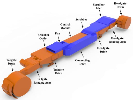
Figure 1.
Design of longwall shearer with an integrated flooded-bed scrubber.
A 3-D model of the flooded-bed dust scrubber system is shown in Figure 2. During operation, the centrifugal fan creates negative pressure and draws dust-laden air from the area near the headgate drum into the scrubber inlet. The dust-laden air passes through the wire mesh screen, where dust particles are entrained in the water droplets created by the water spray. A fraction of dust is filtered by the screen, and the remaining dust particles, encapsulated inside the water droplets, move downwind to the demister. The demister, which consists of parallel sinuous layers of PVC plates, separates the dust-laden water droplets (i.e., black water) from the air before the air reaches the fan. The black water flows down to the sump, where it is discharged by a sump pump. The clean, dry air passes through the fan and is discharged at the outlet.
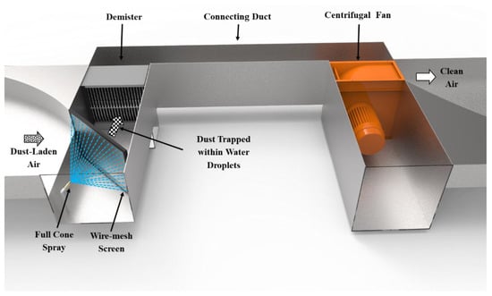
Figure 2.
Three-dimensional model of the flooded-bed scrubber integrated into a longwall shearer.
The wire-mesh screen is placed vertically at an angle of approximately 45° to the scrubber inlet. It consists of 20 layers of woven, 88.9 μm (0.0035 in.), steel mesh screen. A full-cone water spray, placed in front of the screen, delivers 24.6 L/min (6.5 gpm) of water to keep the screen saturated. The 37.3 kW (50-hp) centrifugal fan is rated at 3540 rpm and is capable of drawing 7.0 m3/s (15,000 cfm) of airflow at 2.0 kPa (8.0 in. wg.).
3. Overview of the Longwall Test Gallery
The PRL longwall test gallery is 38.7 m (127.0 ft) long and 2.3 m (7.5 ft) high, as shown in Figure 3. There are 19 metal roof supports, called shields, each 2.0 m (80.0 in.) wide, along the entire length of the face. The headgate drum of the mock-up longwall shearer is placed approximately 14.0 m (46.0 ft) from the air inlet (headgate). A chain of wooden spill guards is placed alongside the physical model for the entire length of the gallery. Wood is used to create the proper coal face profile along the gallery. Plastic tarps are used to create the profile representing broken coal on the armored face conveyor (AFC). Figure 4 shows the inside of the longwall test gallery, taken from the air inlet side. Ventilation of the longwall test gallery is powered by three exhaust fans, connected in parallel, capable of supplying a maximum of 22.2 m3/s (47,040 cfm) of air along the simulated coal face.
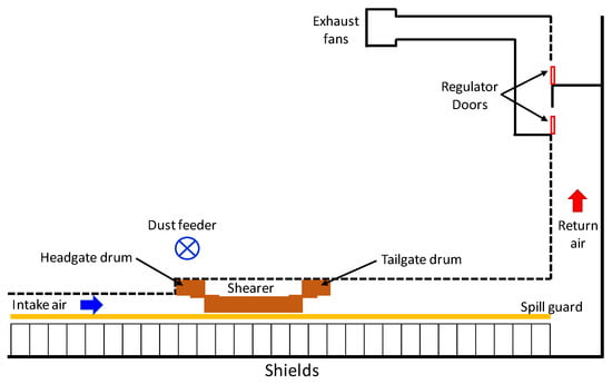
Figure 3.
A plan view of the Pittsburgh Research Laboratory (PRL) longwall test gallery (not to scale).
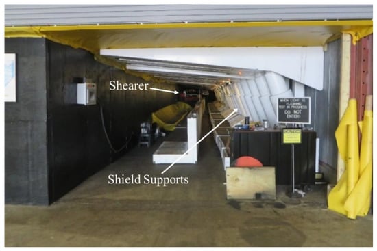
Figure 4.
Longwall test gallery at PRL.
4. Experimental Procedure and Results
Initially, the average velocities of air at the inlet of the flooded-bed scrubber at different fractions of the scrubber fan’s maximum rotational speed were measured, keeping the face air quantity constant. The purpose of this step was to establish a relationship between the quantity of air through the flooded-bed scrubber (scrubber capacity) and the percentage of maximum fan speed. Continuous traversing at the inlet of the flooded-bed scrubber was performed using a vane anemometer. The result of the velocity measurement is presented in Table 1.

Table 1.
Air quantity through scrubber at different fan speeds.
The air quantity survey was performed at four different cross-sections along the length of the test gallery face. The locations of the cross-section from the inlet were 12.0 (39.3 ft), 14.7 (48.37 ft), 17.2 (56.5 ft), and 22.6 m (74.3 ft), respectively (Figure 5). Each cross-section was divided into a 0.61 m × 0.61 m (2.0 ft × 2.0 ft) square grid, and air velocity measurements were taken at points shown as blue dots in Figure 6 using a hot wire anemometer.
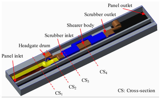
Figure 5.
Three-dimensional CAD drawing of the PRL longwall test gallery.
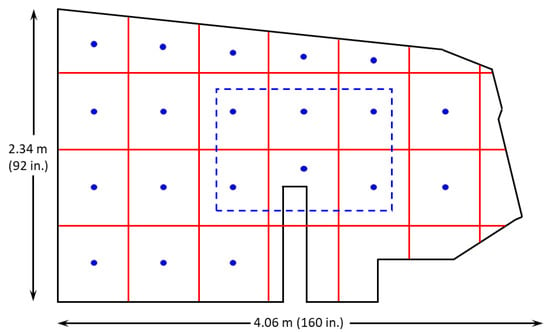
Figure 6.
Cross-section of the longwall panel (not to scale) with 0.61 m x 0.61 m grid and measurement points.
For the first stage comparison, the quantity of air passing through each cross-section was calculated as the product of the area-weighted average velocity and the total area of the cross-section. The experiment was repeated for all four cross-sections with three different percentages of maximum fan speeds: 0% (scrubber fan turned off), 50%, and 100%. The face-air quantity was always kept constant at 23.23 m3/s (49,200 cfm). See Table 2 for the results of the air quantity through different cross-sections at different scrubber capacities. For the second stage comparison, six points from each cross-section were picked. The points were located inside the blue, dashed-line rectangle at the center of each cross-section, as shown in Figure 6. Table 3 presents the velocities at six points for each of the four cross-sections at 0%, 50%, and 100% scrubber fan capacities. The data inside the red, dashed-line rectangle in Table 3 are examples of velocities at six points for cross-section number 2 at 50% scrubber fan capacity.

Table 2.
Results of air quantity survey showing quantity through different cross-sections for different scrubber fan capacities.

Table 3.
Results of air velocity survey showing velocities at six points at each of four cross-sections at different scrubber fan capacities.
5. CFD Modeling
The commercial CFD software package, Cradle SC/Tetra, typically used for thermo-fluid analysis, was used for this study. A 3-D model of the modified shearer in the longwall test gallery was created using a computer-aided design (CAD) package, PTC Creo Parametric 3.0 (see Figure 5). The 3-D model includes the test gallery, modified shearer, shields, and spill plates. The geometry of this arrangement offered no symmetry or periodicity; therefore, a full 3-D simulation was required. This increased the size of the computational domain, and hence the computational time and cost. In order to save computational time, the length of the panel upwind of the modified shearer in the computational domain was shortened by 5.1 m (16.7 ft), assuming streamlined airflow upwind of the shearer’s headgate drum.
First, the geometry was converted into an acceptable STEP file format (.stp) and imported into the Cradle SC/Tetra preprocessing package. The geometry was cleaned for isolated edges and overlapping and intersecting faces, and the computational domain was identified. The boundary surfaces were then registered, and the analysis parameters, such as analysis type (steady or transient simulation), fluid properties, turbulence model, initial conditions, boundary conditions, convergence criteria, and under relaxation factor, were applied. Next, the computational domain was discretized into small volumes creating a network of small elements, called mesh. Both analysis parameters and mesh files were imported into the Cradle SC/Tetra solver package, and simulation was run until a steady-state simulation condition was achieved. Finally, the simulation file was imported into the Cradle SC/Tetra post-processing package, and simulation results were analyzed with different methods, such as contour plots, vector plots, and time-series curves for appropriate graphical representations and reports. The simulations were performed with double precision on a Linux operating system with PC having four, 12 core, 2.4 GHz, AMD processors and 128 GB of RAM. Since the study aimed to validate the CFD model of the longwall gallery using the results of air quantity surveys performed in the longwall test gallery, a single-phase CFD simulation was performed.
5.1. Governing Equations
The fluid (air) was assumed to be incompressible with density and dynamic viscosity values 1.206 kg/m3 and 1.83 × 10⁻⁵ Pa-s, respectively, at an ambient temperature of 20 °C. The numerical simulations to reproduce physical phenomena were performed using the following governing equation [41]:
Mass conservation equation
where is the flow velocity in m/s in direction.
Momentum conservation equation (i direction)
where is the flow velocity in m/s in direction, is the time in second, is the density in m3/s, is the fluid pressure in Pa, is the viscosity in Pa-s, is the gravity in m/s2, is the coefficient of volume expansion in K−1, is the fluid temperature in K, and is the reference fluid temperature K.
Energy conservation equation
where is the density in m3/s, is the fluid pressure in Pa, is the fluid temperature in K, is the specific heat at constant pressure in J/(kg·K), is the thermal conductivity in W/(m.K), and is the heat source in W/m2.
5.2. Turbulence Model
A study was carried out on four turbulence models (Standard k-ε, RNG k-ε, MP k-ε, and Realizable k-ε) to see the effects of the different turbulent models on simulation results. From the steady-state simulations, magnitudes of the average velocity at ten different points in the computational domain for each case were determined, and results were compared. The measurement points were positioned along two straight lines located 1.7 (5.6 ft) and 1.9 m (6.2 ft) above the ground and 12.0 (39.4 ft) and 14.0 m (45.9 ft) from the test gallery inlet, respectively, in the computational domain, as shown in Figure 7. There were five points on the first line spaced 0.5 m (1.6 ft) apart starting 1.5 m (4.9 ft) from the coal face and ending 3.5 m (11.5 ft) from the coal face, while there were five points on the second line spaced 0.5 m (1.6 ft) apart starting 1.8 m (5.9 ft) from the coal face and ending 3.8 m (12.5 ft) from the coal face. The first line was chosen in the high turbulence zone (in front of the scrubber inlet), whereas the second line was chosen in a relatively low turbulence zone (in the middle of the modified shearer). An analysis of steady-state results indicated a maximum deviation of 4.2% among the four turbulence models from their mean velocity, as shown in Figure 8a,b.
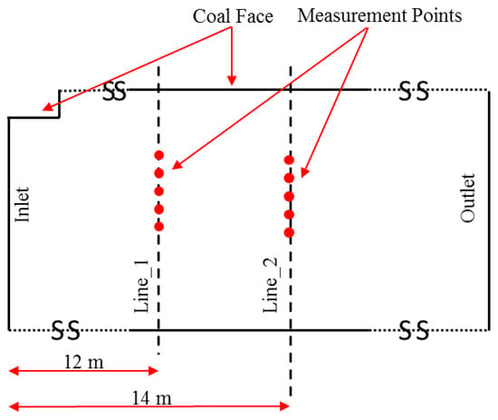
Figure 7.
Plan view of the longwall test gallery (not to scale) showing the locations of point of average velocity measurement for the grid independence test.

Figure 8.
Comparison of average velocity along Line 1 and 2 for the four different turbulence models.
Based on the above findings, the most commonly used and well-validated turbulence model in engineering, the standard k-ε turbulence model was chosen for this study. The standard k-ε turbulence model is a two-equation model, which solves the following two separate transport equations for turbulent kinetic energy, k, and specific dissipation rate, ε.
where is the turbulent energy in m2/s2, is the turbulent dissipation rate in m2/s3, is the generation of turbulent kinetic energy that arises due to mean velocity gradient, is the generation of turbulent kinetic energy that arises due to buoyancy, and is the turbulent Prandtl numbers for the turbulent kinetic energy.
where is the turbulent energy in m2/s2, is the turbulent dissipation rate in m2/s3, is the generation of turbulent kinetic energy that arises due to mean velocity gradient, is the generation of turbulent kinetic energy that arises due to buoyancy, and is the turbulent Prandtl numbers for the turbulent specific dissipation rate. The eddy viscosity, , is given by
where , , , , , and are the empirical constants and their values are 1.0, 1.3, 1.44, 1.92, 0.0, and 0.09, respectively.
5.3. Analysis Conditions
The flow enters the computational domain at the panel inlet, at a constant air quantity, perpendicular to the inlet surface. The panel outlet was imparted a relative static pressure of 0 Pa. Steady-state simulations were run at three different scrubber air capacities. The values for the panel inlet flow rate for the CFD simulations were obtained from the weighted average value of air quantity measured at the panel inlet. As the inlet of the scrubber was withdrawing air from the computational domain, it was given fixed flow quantities of −6.5 (13,700 cfm), −3.0 (6336 cfm), and −0.0 m3/s (0.0 cfm) for the three fan speeds, 100%, 50%, and 0%, respectively. The same values, with opposite signs, were assigned to the outlet of the scrubber. The following equations were used to calculate the turbulence energy and turbulence dissipation rate of the working fluid at the panel inlet.
where k is the turbulence energy in m2/s2, u is the flow velocity at the panel inlet, ε is the turbulence dissipation rate in m2/s2, and D is the equivalent diameter.
Boundary walls were considered to be smooth and stationary, except for the headgate drum, which was assigned a rotating wall condition to mimic the experimental condition. During the laboratory experiments, the headgate drum was given a circular motion to represent the rotating drum during the real shearer operation. No-slip wall conditions were applied to all surfaces, and the standard wall function based on the following logarithmic law (log-law) was used to predict fluid velocity close to the walls of the computational domain.
where u is the flow velocity at position y in m/s, k is the Karman constant (=0.4), y is the distance from boundary wall surface in m, ν is the kinematic viscosity in m2/s, and A is a constant (=5.5).
where u* is the friction velocity in m/s, τ0 is the shear stress in kg/m.s2, and ρ is the fluid density in kg/m3.
where ν is the kinematic viscosity in m2/s, µ is the fluid viscosity in m/s, is the shear stress in kg/m.s2, and ρ is the fluid density in kg/m3.
Iterative convergence was achieved when the order of magnitude decrease in the normalized residuals for all variables was below 10−5 within a cycle, and mass flow was balanced. The pressure-based solver of SC Tetra was used to solve mass, momentum, and energy conservation equations with under-relaxation factor for pressures set to 0.6. Initially, the fluid velocities in X, Y, and Z directions were zero, and the fluid pressure was one atmospheric pressure.
5.4. Computational Mesh
An unstructured tetrahedral computational mesh was generated in the computational domain to achieve a model shape with high accuracy using the finite volume method (Figure 9). Four layers of prism elements with a thickness variation rate of 1.1 were inserted on wall boundaries to capture the effect of walls of the fluid with high numerical accuracy [41]. Computational zones with highly skewed, low-aspect ratio elements were refined to minimize numerical error. In addition, high gradient zones and narrow passages, such as the scrubber inlet and outlet, were also refined. The y+ value (normalized wall distance for a wall-bounded flow) at all walls was maintained between 30 and 300 to permit correct application of logarithmic law wall function, except some extremely low-velocity zones, between the simulated coal face and shearer body. The quality of the mesh generated in the computational domain was good, with average prism layer insertion percentage and h-ratio of the tetrahedral mesh at 99.85% and 0.27, respectively.
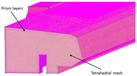
Figure 9.
Mesh in the computational domain (not to scale) showing tetrahedral volume mesh and prism boundary layers.
To ensure that the results obtained through CFD modeling do not depend on the mesh resolution and to explain the physics with utmost accuracy, a grid independence study was carried out. The grid independence study started with a coarse mesh that was gradually refined until the variations in the results were deemed acceptable. Four different cases with a computational domain element growth factor of approximately 1.5 were tested for the scenario in which the scrubber fan was operating at full capacity. The total number of elements in the computational domain for the four cases were 3.8 million, 5.7 million, 8.4 million, and 12.3 million, in that order.
The magnitude of average air velocities was measured and compared on the ten points shown in Figure 7 and Figure 10a,b show the grid independence study results for the average velocity at the points on the first and second lines, respectively, marked in Figure 7. The grid independence study indicated that results became independent of the grid size at 5.7 million elements. A comparison of results, separately at each point, indicated a maximum percentage difference of 1.7% between 5.7 million and 8.4 million mesh resolutions. Based on the results obtained from the grid independence study, the CFD validation was performed at 5.7 million elements in the computational domain.

Figure 10.
Comparison of average velocity along lines 1 and 2 for the four cases of grid independence study.
5.5. CFD Simulations Results
For the first stage comparison, the scalar integration of velocity magnitudes at each cross-section was performed to calculate the average velocity at each cross-section (Figure 5). However, for the second stage comparison, vector integration of velocity magnitude in each of the six 0.61 m × 0.61 m (2.0 ft × 2.0 ft) square grids at each cross-section, was performed to calculate velocity perpendicular to a cross-section in each grid. The values of the airflow quantities at different cross-sections and at different percentages of maximum fan speed are presented in Table 4. Table 5 shows the computed velocities at six points for each cross-section at different scrubber capacities.

Table 4.
Results of computational fluid dynamics (CFD) simulation showing quantity through different cross-sections for different scrubber fan capacities.

Table 5.
Results of CFD simulation showing velocities at six points at each of four cross-sections at different scrubber fan capacities.
6. Results and Discussion
The CFD model was validated using the experimental results. The validated CFD model was used to predict results for addition simulation scenarios. A three-level, two-factor, full-factorial experiment was designed, and the effects of scrubber capacity and face air quantity were analyzed.
6.1. CFD Model Validation
A comparison of the air quantity survey with the CFD simulation results is presented in Table 6 and Table 7. The values in Table 6 and Table 7 show the percentage difference between survey and CFD results, which is calculated by dividing the difference of the survey and CFD results by the survey result. The first stage comparison for the total quantity of air passing through each cross-section indicates a maximum variation of 9.9% at the first cross-section for the 0% fan speed case (Table 6). The second stage comparison for the velocities at six points at each cross-section shows a maximum variation of 18.2% at the first cross-section for the 100% fan speed case, except for one outlier of 23.9% at the fourth cross-section for the 100% fan speed case (Table 7). This large difference could be due to the occurrence of recirculation in that area and the inability of a hotwire anemometer to read air velocities in three dimensions. The simulation results are considered to be reasonably accurate considering the complexity of the geometry, simplifications made in the CFD models to address computational resources, and the experimental errors in measurement.

Table 6.
Comparison of experimental and CFD simulation results for the quantity of air passing through different cross-sections at different scrubber fan capacities.

Table 7.
Comparison of experimental and CFD simulation results for air velocities at six points at each of four cross-sections at different scrubber fan capacities.
6.2. Airflow Simulations
The validated CFD model was used to predict the effects of scrubber capacity and face air quantity on the airflow pattern in the longwall test gallery. A three-level, two-factor, full-factorial (32) experiment was designed that resulted in a total of 3 × 3 = 9 test conditions (Table 8). Since three of the test conditions (Face air quantity at 23.23 m3/s and scrubber capacities at 0%, 50%, and 100%) were already simulated, a total of 9 − 3 = 6 additional simulations were performed.

Table 8.
Factors and levels for the CFD simulation.
6.2.1. Effect of Scrubber
The effect of the flooded-bed scrubber on the airflow pattern for the test conditions with face air quantity at 23.23 m3/s and scrubber capacities at 0%, 50%, and 100% are presented in Figure 11 and Figure 12. Figure 11 shows the average velocity gradients on a plane parallel to the mine floor, whereas Figure 12 presents the velocity gradients on the planes perpendicular to the airflow direction in the longwall panel. A relatively high air velocity is observed near the scrubber inlet with high scrubber capacity. Additionally, a similar trend (high-turbulence region at high scrubber capacity) is seen at the flooded-bed scrubber outlet. The scrubber capacity also influences the airflow in the walkway. The airflow is relatively less turbulent and uniform with the scrubber at low capacity. As a portion of air is passing through the scrubber system, the airflow quantity in the walkway decreases downwind of the scrubber inlet with the increase in the scrubber capacity. In addition, due to the same reason, the airflow in the space between the simulated coal face and the shearer body is low and recirculating as compared to a case with low scrubber capacity. Moreover, a low-velocity recirculation zone was observed between the scrubber and fan modules in all the cases.
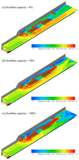
Figure 11.
Average velocity gradient at a plane 1.65 m above the floor with face air quantity at 23.23 m3/s and scrubber capacities at 0%, 50%, and 100%.
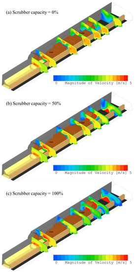
Figure 12.
Average velocity gradient at planes perpendicular to the airflow direction in the test gallery with face air quantity at 23.23 m3/s and scrubber capacities at 0%, 50%, and 100%.
6.2.2. Effect of Face Air Quantity
The effect of face air quantity on the airflow pattern in the longwall test gallery is presented in Figure 13. An increase in face air quantity minimizes the issue of low airflow in the walkway and the space between simulated coal face and shearer body. High face velocity also helps in making the flow more uniform in the walkway.
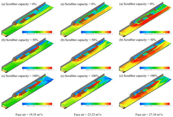
Figure 13.
Comparison of airflow pattern in the longwall test gallery at three different face air quantities.
7. Conclusions
In an attempt to reduce dust concentration at an underground longwall face, the authors fabricated a full-size, physical model of a Joy 7LS longwall shearer with an integrated flooded-bed dust scrubber. The physical model was installed in the longwall test gallery of the NIOSH Pittsburgh Research Laboratory to test its dust capture effectiveness. An air quantity survey was carried out to quantify the distribution of airflow in the longwall test gallery. The survey was performed at four different cross-sections along the face at a fixed face-air quantity for three different scrubber air capacities. A 3-D computer-aided design (CAD) model of the experimental gallery was created, and the validation of a computational fluid dynamics (CFD) model was performed using the survey results. The validation was carried out in two stages. First, a validation of the total quantity of air passing through each cross-section was performed, which resulted in a maximum deviation of 9.9%. Then, a more precise validation of the magnitude of the velocity vector at six points at each cross-section was performed, which showed a maximum 18.2% variation. The validated CFD model was used to analyze the effects of scrubber capacity and face air quantity on the airflow in the longwall panel. The model can be utilized further to understand the impact of the flooded-bed integration on dust reduction in a longwall panel.
Author Contributions
Conceptualization, T.N., J.S. and S.A.; Methodology, J.S. and S.A.; Software, S.A.; Validation, S.A., Formal Analysis, S.A. and J.S.; Investigation, T.N., J.S. and S.A.; Writing—Original Draft Preparation, S.A.; Writing—Review and Editing, J.S. and T.N.; Supervision, J.S. and T.N.; Project Administration, J.S. and T.N.; funding acquisition, J.S. and T.N. All authors have read and agreed to the published version of the manuscript.
Funding
Funding for this research was provided by the Alpha Foundation for the Improvement of Mine Safety and Health (grant number AFC113-10). We want to thank personnel from Joy Global, Inc. and the Tunnel Ridge Longwall Mine (Alliance Resource Partners, L.P.) for their guidance.
Institutional Review Board Statement
Not applicable.
Informed Consent Statement
Not applicable.
Acknowledgments
The authors want to thank the Alpha Foundation for the Improvement of Mine Safety and Health for funding this research. We would also like to thank personnel from Joy Global, Inc. and the Tunnel Ridge Longwall Mine (Alliance Resource Partners, L.P.) for their guidance.
Conflicts of Interest
The authors declare no conflict of interest.
References
- Colinet, J.F.; Spencer, E.R.; Jankowski, R.A. Status of Dust Control Technology on U.S. Longwalls. In Proceedings of the 6th International Mine Ventilation Congress, Pittsburgh, PA, USA, 17–22 May 1997; pp. 345–351. [Google Scholar]
- Rider, J.P.; Colinet, J.F. Current Dust Control Practices on U.S. Longwalls. In Proceedings of the Longwall USA, Pittsburgh, PA, USA, 5–7 June 2007; pp. 1–12. [Google Scholar]
- Fiscor, S. Coal Age; Mining Media International: Jacksonville, FL, USA, 2019; p. 25. [Google Scholar]
- U.S. Energy Information Administration. Annual Coal Report (2018). Available online: http://www.eia.gov/coal/annual/ (accessed on 5 May 2020).
- Lebecki, K.; Małachowski, M.; Sołtysiak, T. Continuous dust monitoring in headings in underground coal mines. J. Sustain. Min. 2016, 15, 125–132. [Google Scholar] [CrossRef]
- Jankowski, R.A.; Organiscak, J.A.; Jayaraman, N.I. Dust Sources and Controls on High Tonnage Longwall Faces. Soc. Min. Eng. Aime Littleton 1990, 9, 73. [Google Scholar]
- Brodny, J.; Tutak, M. Exposure to Harmful Dusts on Fully Powered Longwall Coal Mines in Poland. Int. J. Environ. Res. Public Health 2018, 15, 1846. [Google Scholar] [CrossRef] [PubMed]
- Yuan, J.; Han, R.; Esther, A.; Wu, Q.; Yang, J.; Yan, W.; Ji, X.; Liu, Y.; Li, Y.; Yao, W.; et al. Polymorphisms in autophagy related genes and the coal workers’ pneumoconiosis in a Chinese population. Gene 2017, 632, 36–42. [Google Scholar] [CrossRef] [PubMed]
- U.S. Department of Labor. Lowering Miners’ Exposure to Respirable Coal Mine Dust, Including Continuous Personal Dust Monitors. Fed. Regist. 2014, 79, 24814–24994. Available online: http://arlweb.msha.gov/regs/fedreg/final/2014finl/2014-09084.asp (accessed on 1 May 2014).
- Arnold, C. A Scourge Returns: Black Lung in Appalachia. Environ. Health Perspect. 2016, 124, A13–A18. [Google Scholar] [CrossRef] [PubMed]
- Blackley, D.J.; Halldin, C.N.; Laney, A.S. Continued Increase in Prevalence of Coal Workers’ Pneumoconiosis in the United States, 1970–2017. Am. J. Public Health 2018, 108, 1220–1222. [Google Scholar] [CrossRef]
- Joy, G.J.; Colinet, J.F.; Landne, D.D. Coal workers’ pneumoconiosis prevalence disparity between Australia and the United States. Min Eng. 2012, 64, 65–71. [Google Scholar]
- Castranova, V.; Vallyathan, V. Silicosis and coal workers’ pneumoconiosis. Environ. Health Perspect. 2000, 108, 675–684. [Google Scholar]
- Joy, G.J.; Colinet, J.F.; Landen, D.D. Coal workers’ pneumoconiosis. Min Eng. 2012, 64, 65–71. [Google Scholar]
- Sinclair, J. Environmental Conditions in Coal Mines: Including Fires, Explosions, Rescue and Recovery Work; Pitman, Pennsylvania State University: State College, PA, USA, 1958. [Google Scholar]
- Cohen, R.A.; Petsonk, E.L.; Rose, C.; Young, B.; Regier, M.; Najmuddin, A.; Abraham, J.L.; Churg, A.; Green, F.H.Y. Lung Pathology in U.S. Coal Workers with Rapidly Progressive Pneumoconiosis Implicates Silica and Silicates. Am. J. Respir. Crit. Care Med. 2016, 193, 673–680. [Google Scholar] [CrossRef]
- Laney, A.S.; Petsonk, E.L.; Hale, J.M.; Wolfe, A.L.; Attfield, M.D. Potential Determinants of Coal Workers’ Pneumoconiosis, Advanced Pneumoconiosis, and Progressive Massive Fibrosis Among Underground Coal Miners in the United States, 2005–2009. Am. J. Public Health 2012, 102, S279–S283. [Google Scholar] [CrossRef] [PubMed]
- Almberg, K.S.; Friedman, L.S.; Rose, C.S.; Go, L.H.T.; Cohen, A.R. Progression of coal workers’ pneumoconiosis absent further exposure. Occup. Environ. Med. 2020, 77, 748–751. [Google Scholar] [CrossRef] [PubMed]
- Landen, D.D.; Wassell, J.T.; McWilliams, L.; Patel, A. Coal dust exposure and mortality from ischemic heart disease among a cohort of U.S. coal miners. Am. J. Ind. Med. 2011, 54, 727–733. [Google Scholar] [CrossRef]
- Wang, M.; Jin, Y.; Chen, S.; Yao, S.; Zhu, L.; Duan, J.; Yuan, J. The study of autophagy in alveolar macrophages of patients with coal workers’ pneumoconiosis. Zhonghua Lao Dong Wei Sheng Zhi Ye Bing Za Zhi = Zhonghua Laodong Weisheng Zhiyebing Zazhi = Chin. J. Ind. Hyg. Occup. Dis. 2015, 33, 41–44. [Google Scholar]
- MSHA, Fact Sheet MSHA’s Final Rule to Lower Miners’ Exposure to Respirable Coal Mine Dust. 2014. Available online: https://arlweb.msha.gov/endblacklung/docs/factsheet.pdf (accessed on 25 January 2020).
- Cashdollar, K.L.; Sapko, M.J. Explosion Hazards of Coal Dust in the Presence of Methane. In Handbook for Methane Control in Mining; The National Institute for Occupational Safety and Health (NIOSH): Pittsburgh, PA, USA, 2006; pp. 147–150. [Google Scholar]
- Sapko, M.J.; Cashdollar, K.L.; Green, G.M.; Verakis, H.C. Coal Dust Particle Size Survey of U.S. Mines. J. Loss Prev. Process Ind. 2007, 20, 616–620. [Google Scholar] [CrossRef]
- Harris, M.L.; Cashdollar, K.L.; Man, C.K.; Thimons, E. Mitigating Coal Dust Explosions in Modern Underground Coal Mines. SSRN Electron. J. 2009, 10–13. [Google Scholar] [CrossRef]
- Tan, B.; Liu, H.; Xu, B.; Wang, T. Comparative study of the explosion pressure characteristics of micro- and nano-sized coal dust and methane–coal dust mixtures in a pipe. Int. J. Coal Sci. Technol. 2020, 7, 68–78. [Google Scholar] [CrossRef]
- Xu, H.; Wang, X.; Li, Y.; Zhu, P.; Cong, H.; Qin, W. Experimental investigation of methane/coal dust explosion under influence of obstacles and ultrafine water mist. J. Loss Prev. Process. Ind. 2017, 49, 929–937. [Google Scholar] [CrossRef]
- Niu, Y.; Zhang, L.; Shi, B. Experimental study on the explosion-propagation law of coal dust with different moisture contents induced by methane explosion. Powder Technol. 2020, 361, 507–511. [Google Scholar] [CrossRef]
- Zhou, Y.-H.; Bi, M.-S.; Qi, F. Experimental research into effects of obstacle on methane–coal dust hybrid explosion. J. Loss Prev. Process. Ind. 2012, 25, 127–130. [Google Scholar] [CrossRef]
- Lin, S.; Liu, Z.; Qian, J.; Li, X. Comparison on the explosivity of coal dust and of its explosion solid residues to assess the severity of re-explosion. Fuel 2019, 251, 438–446. [Google Scholar] [CrossRef]
- Wedding, W.C.; Novak, T.; Arya, S.; Kumar, A. CFD Modeling of a Flooded-bed Scrubber Concept for a Longwall Shearer Operating in a U.S. Coal Seam. In Proceedings of the North American Mine Ventilation Symposium, Golden, CO, USA, 20–24 June 2015; pp. 385–390. [Google Scholar]
- U.S. Department of Labor. Report of Investigation, Fatal Underground Coal Mine Explosions; No. 5 Mine; Jim Walter Resources: Brookwood, AL, USA, 23 September 2001; ID No. 01-01322, 2001. [Google Scholar]
- U.S. Department of Labor. Report of Investigation, Fatal Underground Mine Explosion; Upper Big Branch Mine-South; Performance Coal Company, Montcoal: Raleigh County, WV, USA, 2011. [Google Scholar]
- Rider, J.P.; Colinet, J.F. Benchmarking Longwall Dust Control Technology and Practices. Min. Eng. 2011, 63, 74–80. [Google Scholar]
- Wang, W.; Peng, F.F. Analyses of Respirable Dust Distributions with Multiple Dust Sources on Longwall Faces. Proc. Soc. Min. Metall. Explor. 1991, 367–375. [Google Scholar]
- Arya, S.; Wedding, W.C.; Kumar, A.; Novak, T. CFD Modeling of a Novel Wet Scrubber for Capture of Respirable Dust in an Underground Coal Mine. In Proceedings of the SME ACE 2016, SME Annual Conference & Expo, Phoenix, AZ, USA, 21–24 February 2016; pp. 16–161. [Google Scholar]
- U.S. Department of Labor. Final Rule, 79 (2014). Available online: http://arlweb.msha.gov/regs/fedreg/final/2014finl/2014-09084.asp (accessed on 16 March 2020).
- Colinet, J.F.; Reed, W.R.; Potts, J.D. Continuous Mining Dust Levels in 20-Foot Cuts with and without a Scrubber Operating. In Proceedings of the Society for Mining, Metallurgy & Exploration, Salt Lake City, UT, USA, 23–26 February 2014; pp. 14–33. [Google Scholar]
- Exposure to Silica Dust on Continuous Mining Operations Using Flooded-Bed Scrubbers. Appl. Occup. Environ. Hyg. 2002, 17, 322–323. [CrossRef] [PubMed]
- Arya, S.; Wedding, W.C.; Novak, T.; Kumar, A.; Levy, A. Pressure Drop Measurement across Flooded-bed Scrubber Screen and Demister in a Laboratory Setup for its Use in a Longwall Shearer. In Proceedings of the 16th North American Mine Ventilation Symposium, Golden, CO, USA, 17–22 June 2017; p. 15-1. [Google Scholar]
- Arya, S.; Sottile, J.; Novak, T. Development of a flooded-bed scrubber for removing coal dust at a longwall mining section. Saf. Sci. 2018, 110, 204–213. [Google Scholar] [CrossRef]
- Software Cradle Co. Ltd. User’s Guide Basics of CFD Analysis; Software Cradle Co. Ltd.: Osaka, Japan, 2015. [Google Scholar]
Publisher’s Note: MDPI stays neutral with regard to jurisdictional claims in published maps and institutional affiliations. |
© 2021 by the authors. Licensee MDPI, Basel, Switzerland. This article is an open access article distributed under the terms and conditions of the Creative Commons Attribution (CC BY) license (https://creativecommons.org/licenses/by/4.0/).