


Abstract
This study proposes a tension-spring-based unidirectional rotational stiffness mechanism (TS-URM) and its implementation in a Unidirectional Series Elastic Actuator (USEA). Unlike conventional bidirectional rotary SEAs, the proposed design is structurally optimized for unidirectional torque transmission, improving deformation utilization efficiency in pulling-type applications. An analytical model was derived to establish the geometric relationship between spring elongation and rotational deformation, enabling explicit formulation of the torque–angle relationship. The influence of the installation angle on stiffness linearity was systematically analyzed, and a multilayer spring configuration was optimized to achieve a target rotational stiffness of approximately 42 Nm/rad. A preload adjustment mechanism was incorporated to eliminate nonlinear behavior in the initial operating region. Experimental results validated the analytical model and demonstrated stable unidirectional force control up to 130 N with steady-state errors within 1 N. The proposed mechanism provides predictable stiffness characteristics and an efficient structural solution for compact USEA systems.
1. Introduction
A Series Elastic Actuator (SEA) is an actuation structure in which an elastic element is placed in series between the actuator and the load, enabling simultaneous implementation of force control and mechanical compliance. SEAs have been widely applied in various fields, ranging from automotive systems to robotic platforms [1,2,3]. Since the external force can be indirectly estimated from the deformation of the elastic element, accurate force control can be achieved without the need for expensive dedicated force sensors. In addition, the elastic element absorbs external impacts, thereby improving system safety. Owing to these characteristics, SEAs have been actively studied in applications that require precise force regulation and safety, such as Human–Robot Interaction (HRI) [4], wearable robots [5], rehabilitation robots [6], and collaborative robots [7].
The performance of an SEA strongly depends on the mechanical properties of the elastic element, particularly its stiffness [8]. In rotary SEA configurations, stiffness design is a key issue, as the stiffness value directly affects the control characteristics and dynamic response of the system [8,9]. A low stiffness allows larger elastic deformation, which improves force measurement resolution. However, it may limit the achievable control bandwidth. In contrast, a high stiffness improves force transmission bandwidth but reduces compliance, potentially decreasing interaction safety. Therefore, in the design of rotational stiffness, it is important to balance force control accuracy, dynamic response, and mechanical safety. To achieve this balance, a stiffness realization mechanism that is predictable and structurally straightforward to design is required.
Various mechanical approaches have been proposed to realize rotational stiffness. The first approach employs structural torsional elastomers, in which rotational deformation is induced through planar geometries or specially designed cross-sectional shapes [10,11]. Carpino et al. proposed a compact monolithic torsional spring and validated its performance by comparing FEM-based optimization results with experimental measurements [10]. Similarly, Wang et al. introduced a flat torsional spring incorporating corrugated flexible units, and its stiffness characteristics were verified through finite element analysis [11]. These structures offer high space efficiency and are advantageous for compact robotic systems. However, to enable sufficient torsional deformation within a limited volume, the geometry inevitably becomes complex. As a result, it is difficult to analytically derive the relationship between geometric parameters and stiffness characteristics. Moreover, nonlinear elastic behavior arising from complex geometries complicates the prediction of the torque–displacement relationship, often requiring reliance on FEM simulations or iterative experimental validation during the design stage.
The second approach utilizes compression spring arrays to generate rotational stiffness [12,13]. In this configuration, two or more compression springs are arranged between a fixed and a rotating component, forming an equivalent rotational stiffness through parallel spring combinations. Although stiffness can be adjusted by varying the number and angular placement of springs, compression springs are inherently vulnerable to buckling and bending deformation. When large deflections are involved, additional guiding structures are required to prevent buckling, which increases mechanical complexity and introduces frictional elements. Furthermore, proper preload design is essential, and this may increase system nonlinearity.
To overcome these limitations, rotational stiffness mechanisms based on tension spring arrays have been proposed [14,15]. Compared to compression springs, tension springs exhibit a lower risk of buckling and provide greater structural stability. They can offer relatively linear force–displacement characteristics over a wider operating range. By symmetrically arranging multiple tension springs, rotational stiffness can be achieved while maintaining structural simplicity and effective load distribution. However, most existing tension-spring-based rotary SEA designs assume bidirectional operation, meaning that identical elastic characteristics are provided in both directions of rotation. While suitable for general robotic applications, such configurations may lead to structural inefficiency in applications where actuation is required primarily in one direction.
In many industrial and special-purpose systems, force generation is required only in one direction. Examples include pulling-type exercise devices [16], roll-to-roll systems [17], and cable-driven tension control systems [18,19,20]. These systems are fundamentally designed for pulling-type actuation, where continuous force generation in a specific direction is the primary objective. In such applications, force control is necessary, but the effective force transmission direction is practically unidirectional. Nevertheless, when conventional bidirectional SEA structures are employed, only half of the available elastic deformation range is effectively utilized, while the remaining deformation region remains structurally unused. Consequently, the achievable effective torque range within a given volume is reduced, leading to inefficient space utilization. Therefore, a rotational stiffness mechanism specifically tailored for unidirectional applications is required, and an SEA design optimized for unidirectional operation becomes necessary.
In this study, a tension-spring-based rotational stiffness mechanism for a Unidirectional Series Elastic Actuator (USEA) is proposed. The proposed mechanism consists of coaxially arranged inner and outer brackets connected by multiple tension springs, optimized for unidirectional rotational deformation. The geometric relationship between rotational angle and spring elongation is analytically derived, enabling explicit formulation of the torque–displacement relationship. Based on this analytical model, the relationship between design parameters and rotational stiffness is systematically clarified. In addition, the influence of the installation angle of the springs on stiffness linearity and characteristic curves is analyzed to improve design predictability. Furthermore, the inherent initial tension of tension springs may introduce nonlinearity in the initial operating region. To address this issue, a preload adjustment mechanism is incorporated to shift the operating range into a linear region of the spring characteristic. Based on the proposed rotational stiffness mechanism, a USEA is designed and fabricated. Experimental results validate the analytical model and demonstrate the force control performance of the proposed system.
The main contributions of this study are summarized as follows:
- 1.
- A tension-spring-based rotational stiffness mechanism specifically optimized for unidirectional applications is proposed and analytically modeled;
- 2.
- The effect of the installation angle on stiffness characteristics is analyzed, providing practical design insights;
- 3.
- A USEA integrating the proposed mechanism is implemented and experimentally validated.
2. Analytical Modeling of a Tension-Spring-Based Unidirectional Rotational Stiffness Mechanism
This section introduces the Tension-Spring-Based Unidirectional Rotational Stiffness Mechanism (TS-URM), which is designed for unidirectional force transmission. The proposed mechanism generates rotational stiffness by utilizing the geometric arrangement of tension springs and the variation in their lengths induced by rotational motion. First, the configuration and working principle of the mechanism are described. Subsequently, the variation in spring length due to rotational displacement and the resulting torsional torque are analytically derived. The influence of the installation angle of the springs on the linear and nonlinear characteristics of the rotational stiffness is then analyzed. Finally, the validity of the derived analytical model is verified through simulation.
2.1. Mechanism Configuration and Working Principle
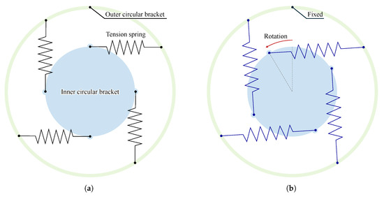
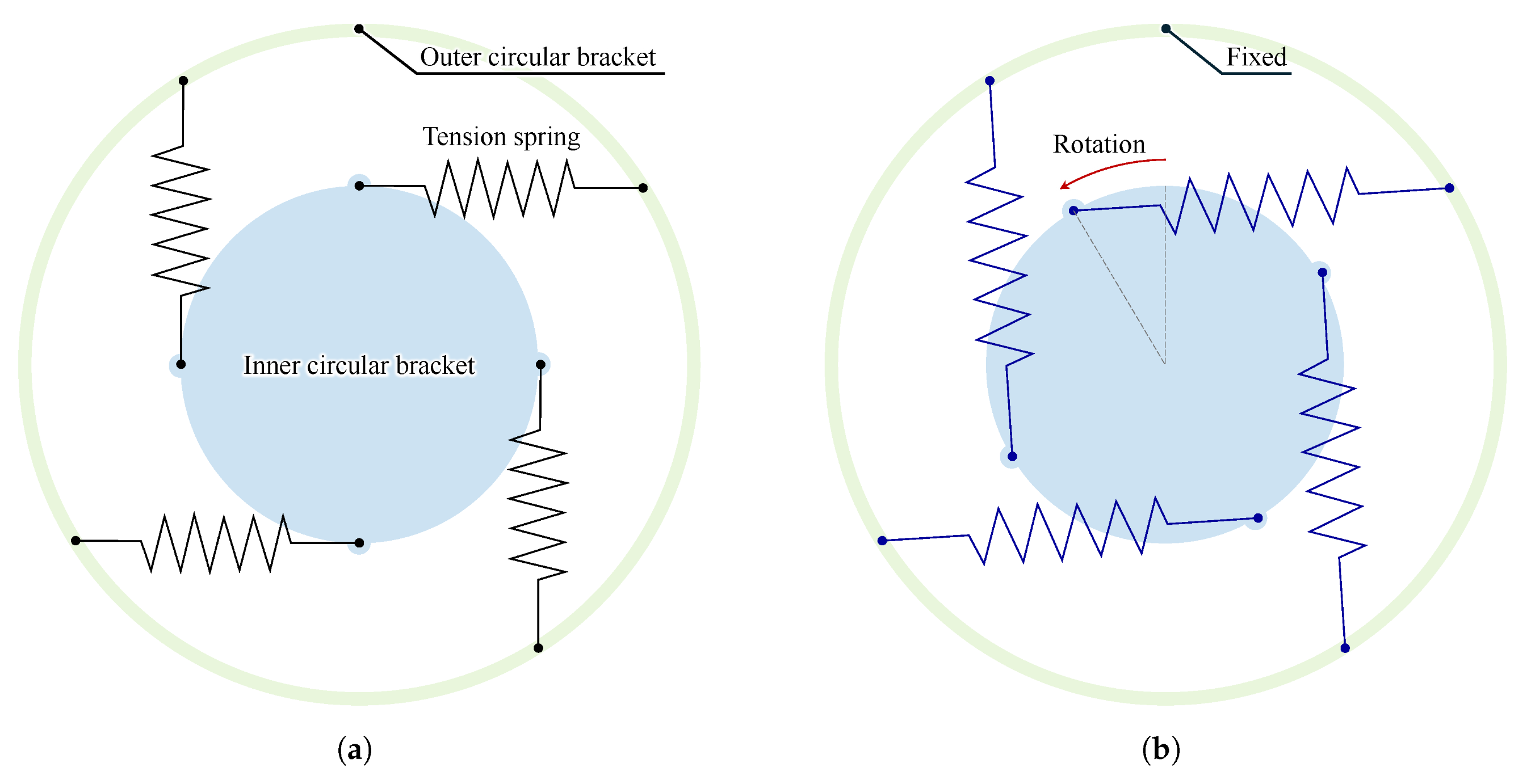
The proposed TS-URM is a rotational stiffness implementation device intended for systems requiring continuous force transmission in a single direction. A conceptual diagram of the mechanism is presented in Figure 1a. The blue circle represents the inner bracket, which rotates in the counterclockwise direction under external input. The green circle represents the outer bracket, which is fixed with respect to the global reference frame.
Figure 1.
Schematic diagram for the TS-URM: (a) static configuration; (b) rotational configuration.
Multiple tension springs are connected between the inner bracket and the outer bracket, and the springs are arranged at equal angular intervals with respect to the center of the inner bracket. This uniform distribution is essential to prevent force imbalance during rotation and to suppress the occurrence of eccentric loading in a specific direction. If the springs are arranged asymmetrically, a moment imbalance about the rotational center may arise, which can degrade the structural stability of the mechanism.
The key characteristic of the proposed mechanism is based on the physical property of tension springs. A tension spring generates a restoring force only when it is elongated, and it cannot structurally transmit force under compressive loading. Accordingly, when the springs are installed, the inner bracket elongates the springs and thus restores force only in a specific direction of rotation. In contrast, for the opposite rotational direction in which the springs would experience contraction, the springs cannot maintain tensile force, and no effective restoring torque is generated. As a result, the proposed mechanism inherently exhibits a unidirectional torque transmission characteristic. As illustrated in Figure 1b, since the outer bracket is fixed, the torsional torque transmitted between the inner and outer brackets can be calculated if the rotational angle of the inner bracket and the spring stiffness are known. Because the springs are radially arranged about the center of the inner bracket, both structural stability and load distribution can be simultaneously achieved.
2.2. Analysis of Rotational Stiffness
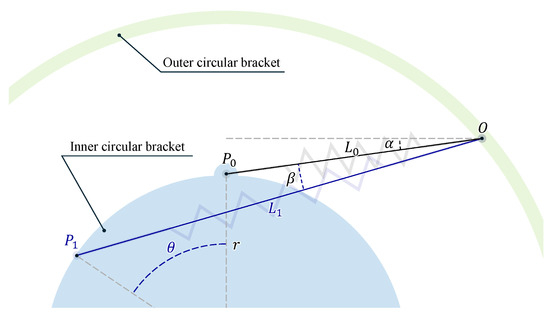
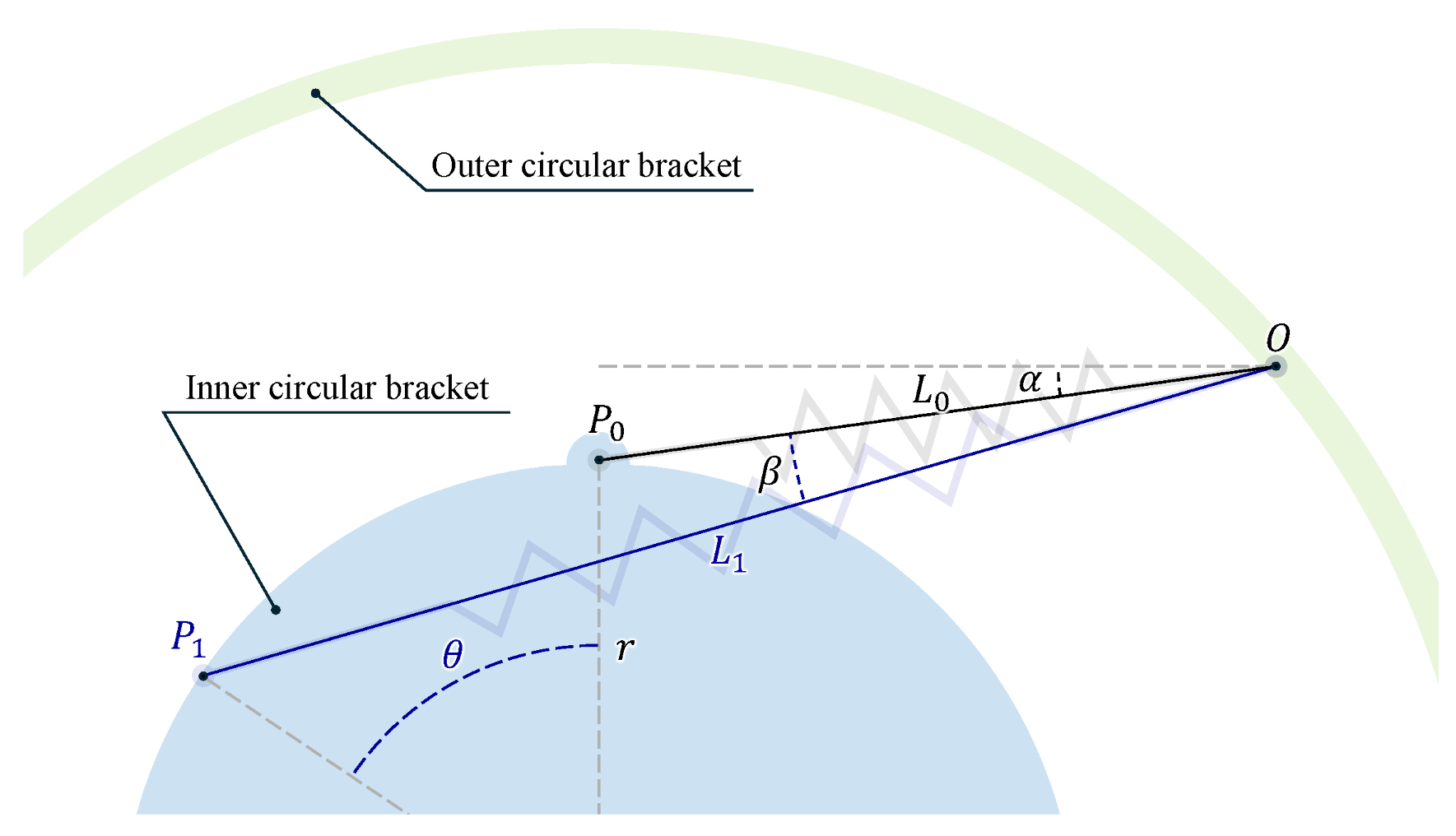
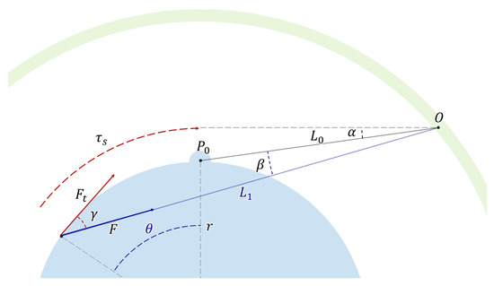
In order to accurately calculate the transmitted torque between the inner bracket and the outer bracket, it is necessary to analytically derive the variation in spring length induced by rotation and the corresponding restoring force. Figure 2 illustrates the geometric relationship of the spring as the inner bracket rotates. The change in length of the tension spring is defined as follows:
where denotes the initial length of the spring, and represents the spring length after the inner bracket has rotated. When the inner bracket rotates by an angle , the orientation of the spring changes from its installation angle. Through kinematic analysis, the variation in the spring angle can be expressed as follows:
where denotes the angular variation of the tension spring, is the installation angle of the tension spring, r is the radius of the inner bracket, and is the rotational angle of the inner bracket. Based on the triangular geometric relationship, the spring length can be determined, and consequently, the length variation can be expressed as a function of the inner bracket rotation angle and the spring angle variation as follows:
Figure 2.
Geometric relationship of the TS-URM.
The restoring force generated in the spring can then be calculated according to Hooke’s law as follows:
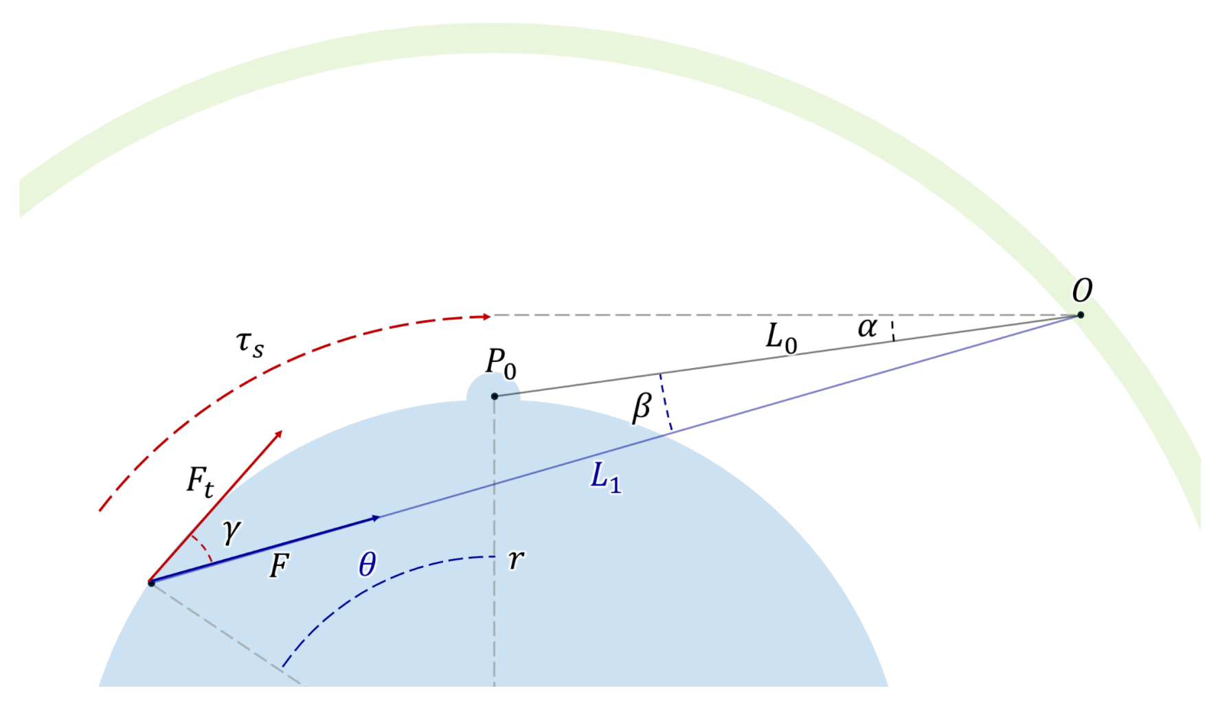
where F denotes the restoring force of the spring, and is the spring stiffness constant. Since this restoring force acts along the axial direction of the spring, only its tangential component contributes to the rotational motion. As illustrated in Figure 3, the restoring force F can be decomposed into its tangential component as follows:
where represents the angle between the spring restoring force and the tangential direction, and denotes the tangential component of the restoring force generated by the spring. Consequently, the torsional torque applied to the inner bracket can be expressed as follows:
where denotes the torsional torque acting on the inner bracket. This torque can be further expressed in relation to the rotational angle and the rotational stiffness as follows:
where K represents the rotational stiffness. From this relationship, the rotational stiffness can be defined as follows:
Figure 3.
Geometric analysis for determining the tangential component of the restoring force.
Therefore, the rotational stiffness of the proposed mechanism is a function of the rotation angle , rather than a constant linear coefficient. In other words, it exhibits nonlinear stiffness characteristics that vary with the rotational displacement. This nonlinearity originates from the trigonometric terms included in the spring length variation equation. In particular, the installation angle significantly influences the nonlinear components of the stiffness behavior.
2.3. Effects of Installation Angle of the Tension Spring
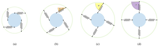
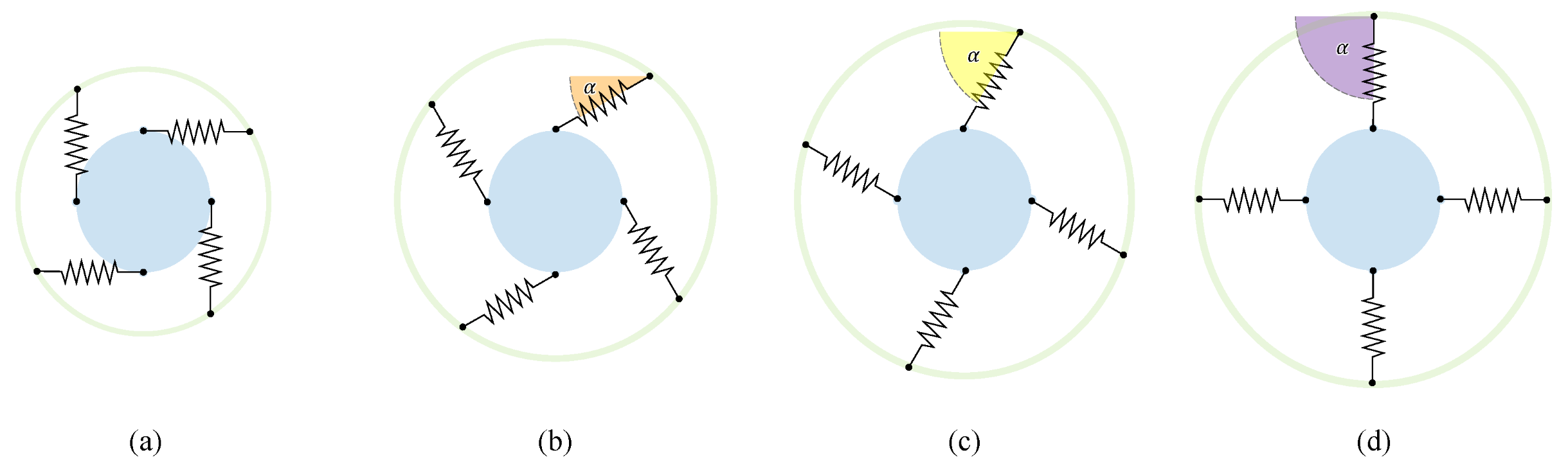
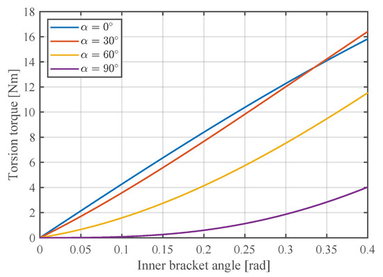
In the preceding analytical derivation, it was confirmed that the installation angle directly affects the rotational stiffness characteristics of the mechanism. To quantitatively investigate this influence, was set to 0°, 30°, 60°, and 90° (Figure 4), and the resulting torsional torque was compared as a function of the rotation angle . All other design parameters were kept identical to ensure a consistent comparison.
Figure 4.
Schematic diagram for analyzing the effect of the installation angle of the tension spring. (a) 0°, (b) 30°, (c) 60°, (d) 90°.
The results are presented in Figure 5. The blue, red, yellow, and purple curves correspond to installation angles of 0°, 30°, 60°, and 90°, respectively. As observed in Figure 5, when the initial angle is 0°, the torque–rotation relationship is closest to linear. This is because the deformation direction of the spring is relatively aligned with the tangential direction of rotation, resulting in a tangential force component that increases approximately linearly with respect to the rotation angle of the inner bracket. As the installation angle increases, the relative angle between the spring axis and the tangential direction varies in a nonlinear manner during rotation. Consequently, the torsional torque also exhibits nonlinear characteristics with respect to . In particular, when , the tangential component changes rapidly as the inner bracket rotates, leading to the most pronounced nonlinear behavior among the considered cases.
Figure 5.
Relationship between the torsional torque and the rotation angle of the inner bracket.
In addition to stiffness linearity, the installation angle is directly related to the diameter of the outer bracket. A larger initial angle results in a larger radial placement of the springs, thereby increasing the required radius of the outer bracket and consequently enlarging the overall spatial footprint of the mechanism. Conversely, a smaller installation angle leads to a more compact configuration and improved space efficiency. Therefore, a small installation angle is advantageous from both stiffness linearity and spatial efficiency perspectives. It should be noted, however, that linear stiffness is not universally optimal for all applications. In certain systems, intentionally exploiting nonlinear stiffness characteristics—such as achieving low stiffness in the initial region and higher stiffness in large-deformation regions—may be beneficial. Nevertheless, for general force control systems, higher linearity simplifies controller design and facilitates stability analysis. For this reason, linearity was selected as one of the primary design criteria in this study.
2.4. Model Validation via Simulation
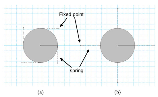
To validate the accuracy of the derived analytical model, a multibody dynamics simulation was conducted using Working Model 2D (version 5.1.2.53, MSC.Software, San Mateo, CA, USA), a simulation tool capable of precisely implementing kinematic constraints and spring elements. In this study, the tension springs were modeled as linear elastic elements.
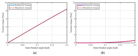
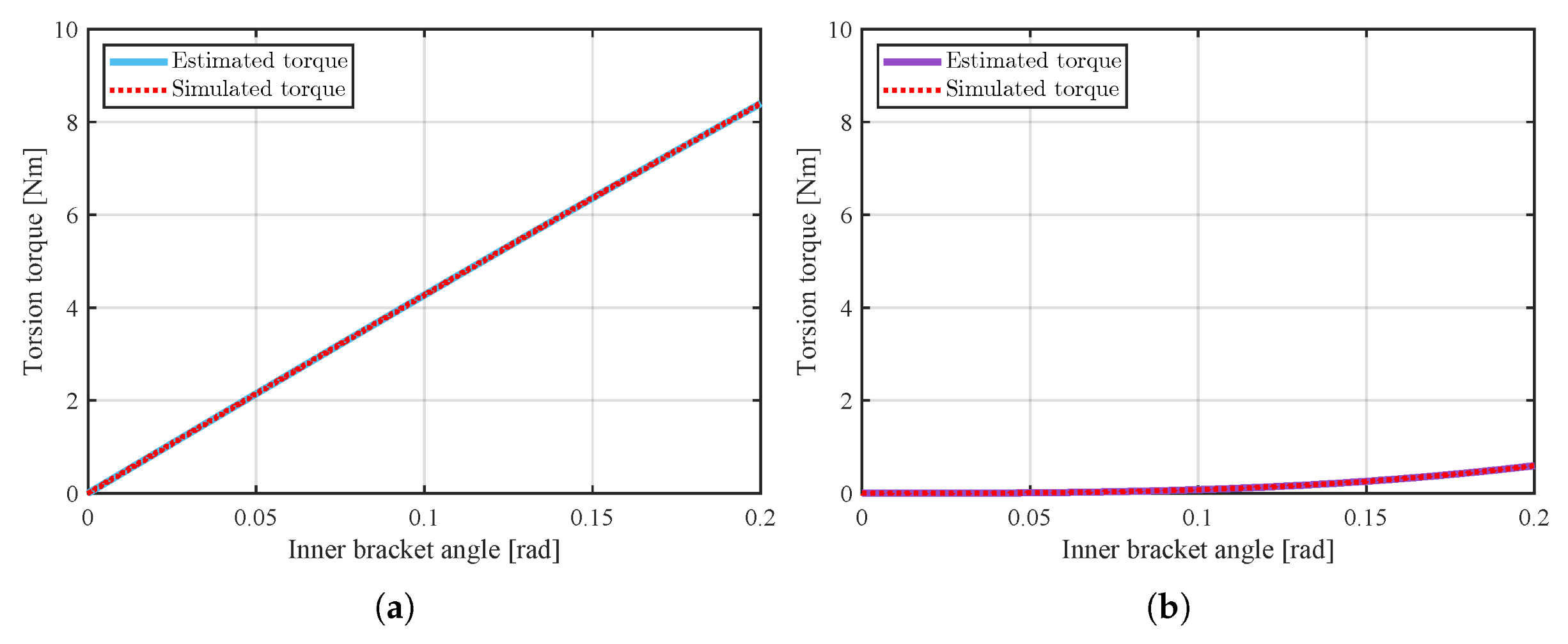
Figure 6 presents the simulation models used for validation. Case (a) corresponds to , while case (b) represents . A gradually increasing rotational displacement was applied to the inner bracket, and the resulting torsional torque was computed. The results shown in Figure 7a,b compare the simulation and analytical outcomes. The red dashed curves represent the simulation results, whereas the blue and purple solid curves correspond to the torque calculated using the analytical model. These outcomes exhibit close agreement over the entire rotation range. This indicates that the derived geometric model accurately captures the mechanical behavior of the proposed mechanism. Furthermore, the variation in nonlinear stiffness characteristics induced by different installation angles was also accurately predicted by the analytical model. Therefore, the proposed analytical formulation can be effectively utilized during the design stage of the TS-URM to predict rotational stiffness and to determine optimal design parameters.
Figure 6.
Simulation environment for assessing the effect of the initial spring installation angle. (a) 0°, (b) 90°.
Figure 7.
Comparison of simulation and analytical results for different installation angles: (a) 0°, (b) 90°.
3. Design and Implementation of the USEA
This section describes the design and implementation process of the USEA, which was developed by integrating the previously proposed TS-URM into an actual actuation system. First, the overall system architecture is introduced. Then, the structural optimization process of the TS-URM to satisfy the target design specifications is described in detail. Finally, the preload design, which is an essential consideration in tension-spring-based structures, is addressed.
3.1. Architecture of the Proposed USEA
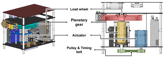
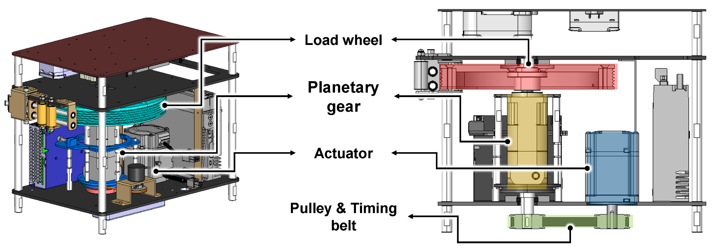
The overall layout of the developed USEA system is shown in Figure 8. The component indicated in blue represents the motor that generates the driving torque, while the yellow component corresponds to the planetary gearbox. If the planetary gearbox is directly fixed to the ground, the system functions as a conventional rigid actuator. In this study, however, the TS-URM was inserted between the gearbox output shaft and the fixed structure to realize a series elastic configuration. Accordingly, the proposed USEA is designed to indirectly measure and control the transmitted torque through the rotational deformation of the TS-URM. Unlike conventional bidirectional SEAs, the proposed architecture is designed under the assumption of unidirectional torque transmission. As a result, the structure is inherently simpler and offers improved spatial efficiency.
Figure 8.
Overall system configuration of the developed USEA.
3.2. Stiffness Mechanism Optimization
This subsection presents the design process of the TS-URM to satisfy the target rotational stiffness. The design requirements were defined as follows:
- The structure should maximize the linearity of the spring behavior;
- Spatial efficiency should be maximized within a limited volume;
- The target rotational stiffness of 42 Nm/rad should be achieved.
To meet these requirements, the following key design variables were considered: the type and stiffness of the springs (), the total number of springs (), the number of springs arranged per layer (), and the number of axial stacking layers ().
3.2.1. Type of Spring
As analyzed in Section 2, minimizing the installation angle is advantageous for improving the linearity of the rotational stiffness while maintaining high spatial efficiency. From a theoretical standpoint, the highest linearity is achieved when . However, in practical mechanical design, interference between fastening bolts and nuts used to assemble the brackets must be taken into account. Therefore, an installation angle of 4.5° was selected as the minimum angle that avoids mechanical interference. Based on this configuration, the diameters of the inner and outer brackets were determined, and consequently, the free length of the spring was set to 40 mm. Three candidate springs satisfying this free-length condition were selected. The spring constants of each candidate and the required number of springs to achieve the target rotational stiffness are summarized in Table 1.
Table 1.
Characteristics of the candidate springs.
3.2.2. Number of Springs in a Layer
The number of springs arranged in a single layer is a critical design variable in the TS-URM configuration. Increasing the number of springs per layer can reduce the required number of layers for a given total number of springs, which may be advantageous from the perspective of axial space utilization. In other words, reducing the number of layers shortens the overall length of the structure and may simplify the manufacturing process. However, increasing the number of springs per layer also increases the likelihood of geometric interference between adjacent springs during rotational motion. As the inner bracket rotates, each spring undergoes a different angular displacement. Depending on the outer diameter of the springs and their deformation magnitude, neighboring springs may come into contact with one another. Such interference is not merely a geometric concern; it limits the maximum allowable rotation angle and reduces the effective operating range of the system.
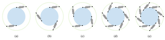
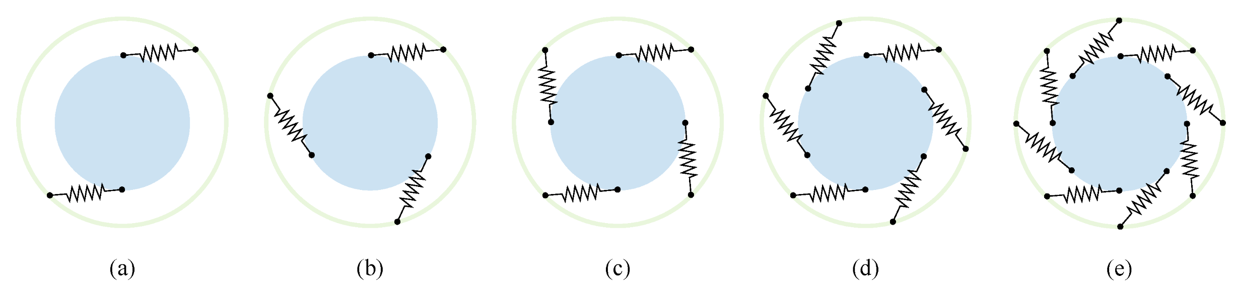
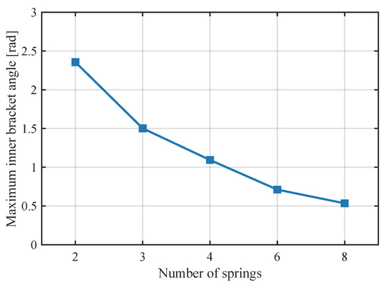
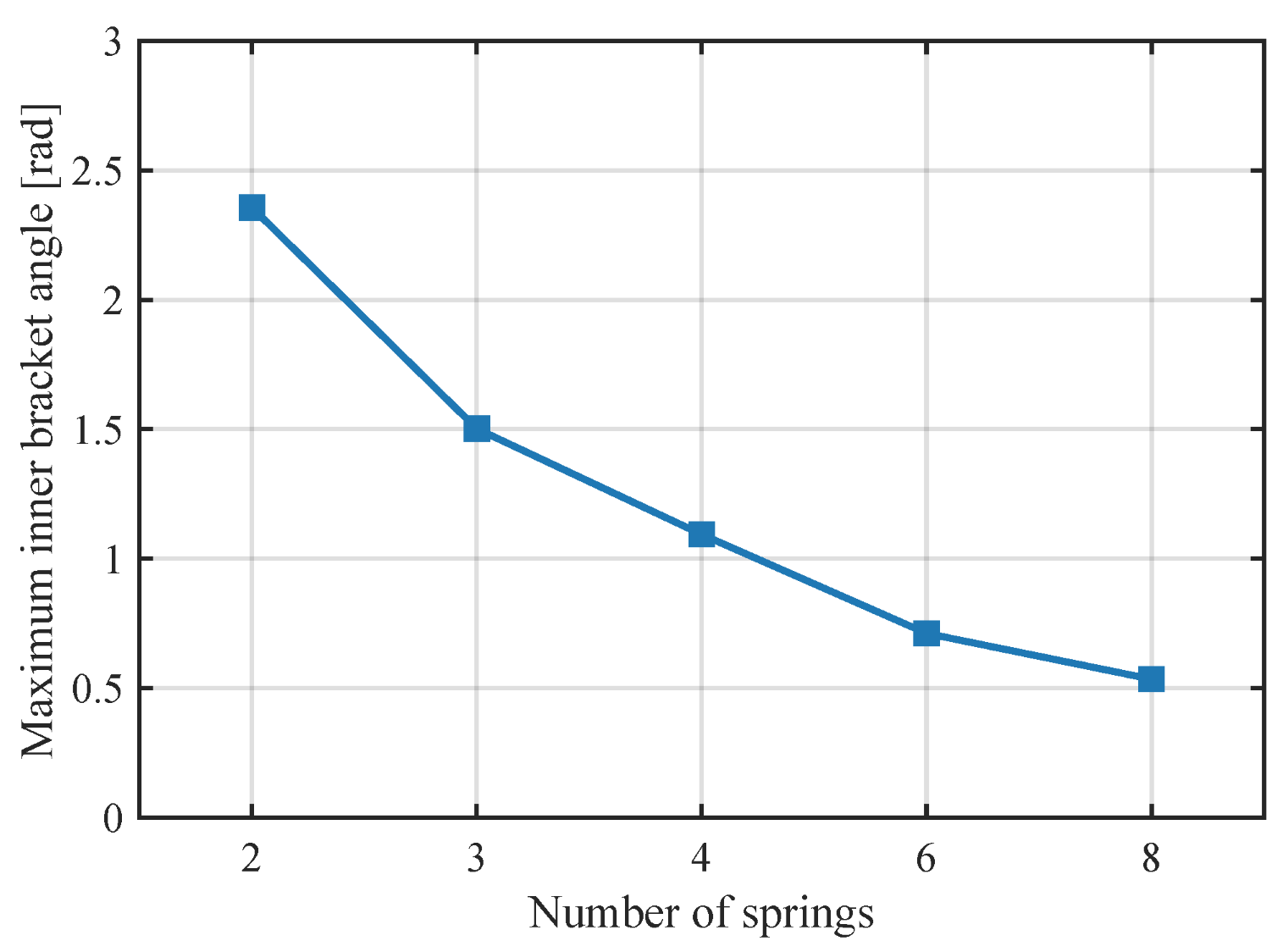
To quantitatively evaluate this effect, the number of springs per layer was set to 2, 3, 4, 6, and 8, and the maximum allowable rotation angle of the inner bracket was calculated for each case (Figure 9). The maximum rotation angle was defined as the point at which the minimum distance between adjacent springs becomes zero. The results presented in Figure 10 clearly show that the allowable rotation angle of the inner bracket decreases as the number of springs per layer increases.
Figure 9.
Schematic illustration of spring configurations per layer: (a) 2 springs, (b) 3 springs, (c) 4 springs, (d) 6 springs, (e) 8 springs.
Figure 10.
Relationship between the number of springs per layer and the maximum rotation angle of the inner bracket.
This phenomenon can be explained geometrically. As the number of springs arranged in a single layer increases, the initial angular spacing between adjacent springs decreases. When the inner bracket rotates, the inclination of each spring changes, resulting in a rapid variation in the relative position between neighboring springs. Consequently, interference occurs earlier for a given rotation angle when more springs are densely arranged in a single layer. A reduction in the allowable rotation angle limits the maximum achievable deformation under the same stiffness condition. In SEA structures, the magnitude of elastic deformation is directly related to force measurement resolution. Therefore, it is important to ensure a sufficient rotation range, and simply increasing the number of springs per layer is not always desirable.
Based on these considerations, the following design strategy was adopted in this study:
- The number of springs per layer was minimized as much as possible;
- The total number of springs was secured through axial layer stacking.
Instead of densely arranging springs within a single plane, a multilayer structure was formed along the axial direction based on the principle of parallel spring combination. This stacked configuration increases the overall stiffness through parallel effects while preserving sufficient rotational allowance for each layer. At the same time, it enhances space utilization and maintains structural stability. Considering the axial space constraints of the system, a maximum of three stacking layers was deemed feasible. Accordingly, a three-layer configuration was applied to each candidate spring, and the required number of springs per layer was calculated to satisfy the target rotational stiffness of 42 Nm/rad. The results are summarized in Table 2.
Table 2.
Optimization design approach using selected candidate springs.
For the three candidate springs (a), (b), and (c), a three-layer configuration was applied. The required number of springs per layer was determined to be 4, 2, and 7, respectively. These values were calculated to simultaneously satisfy the following conditions:
- Achievement of the target rotational stiffness;
- Minimization of the number of springs per layer;
- Full utilization of the maximum allowable axial layers (three layers).
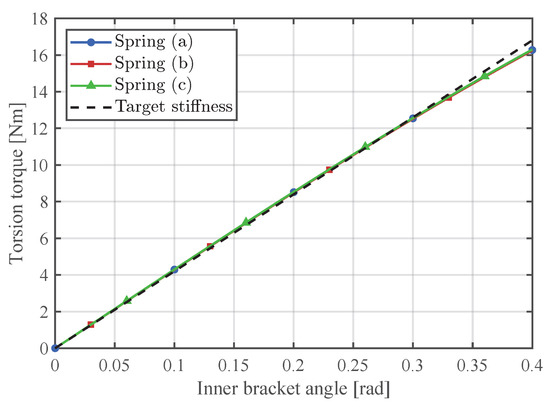
Figure 11 compares the rotational stiffness characteristics of the TS-URM for each candidate spring. The results corresponding to springs (a), (b), and (c) are shown as blue, red, and green solid curves, respectively, while the target stiffness of 42 Nm/rad is indicated by a black dashed line. All three candidates satisfy the target stiffness requirement. However, the final selection was not based solely on the stiffness magnitude. Load distribution characteristics, structural stability, and allowable rotation range were comprehensively considered.
Figure 11.
The rotational stiffness characteristics of the TS-URM for each candidate spring.
Candidate (b), which requires only two springs per layer, offers the simplest configuration and is advantageous from a manufacturing perspective. However, the load applied to each individual spring is relatively high, increasing the likelihood of excessive stress concentration in specific springs. This may lead to reduced fatigue life and potential structural instability under repeated loading conditions. Candidate (c), which requires seven springs per layer, provides the most favorable load distribution. Nevertheless, the narrow spacing between adjacent springs reduces the allowable rotation angle of the inner bracket, thereby limiting the effective deformation range. Candidate (a), consisting of four springs per layer, was determined to provide a balanced design between load distribution and rotational allowance. Accordingly, spring (a) was selected as the final design.
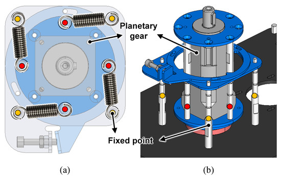
Figure 12 illustrates the USEA configuration implemented using the selected spring. The yellow points represent the fixed points attached to the ground, while the red points correspond to the inner bracket that rotates together with the planetary gearbox. Four tension springs form one layer between these two structures, and the same configuration is axially stacked into three layers, resulting in a total of 12 springs connected in parallel.
Figure 12.
Configuration of the USEA incorporating the selected spring: (a) top view; (b) isometric view.
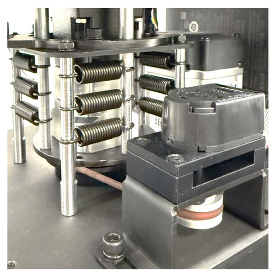
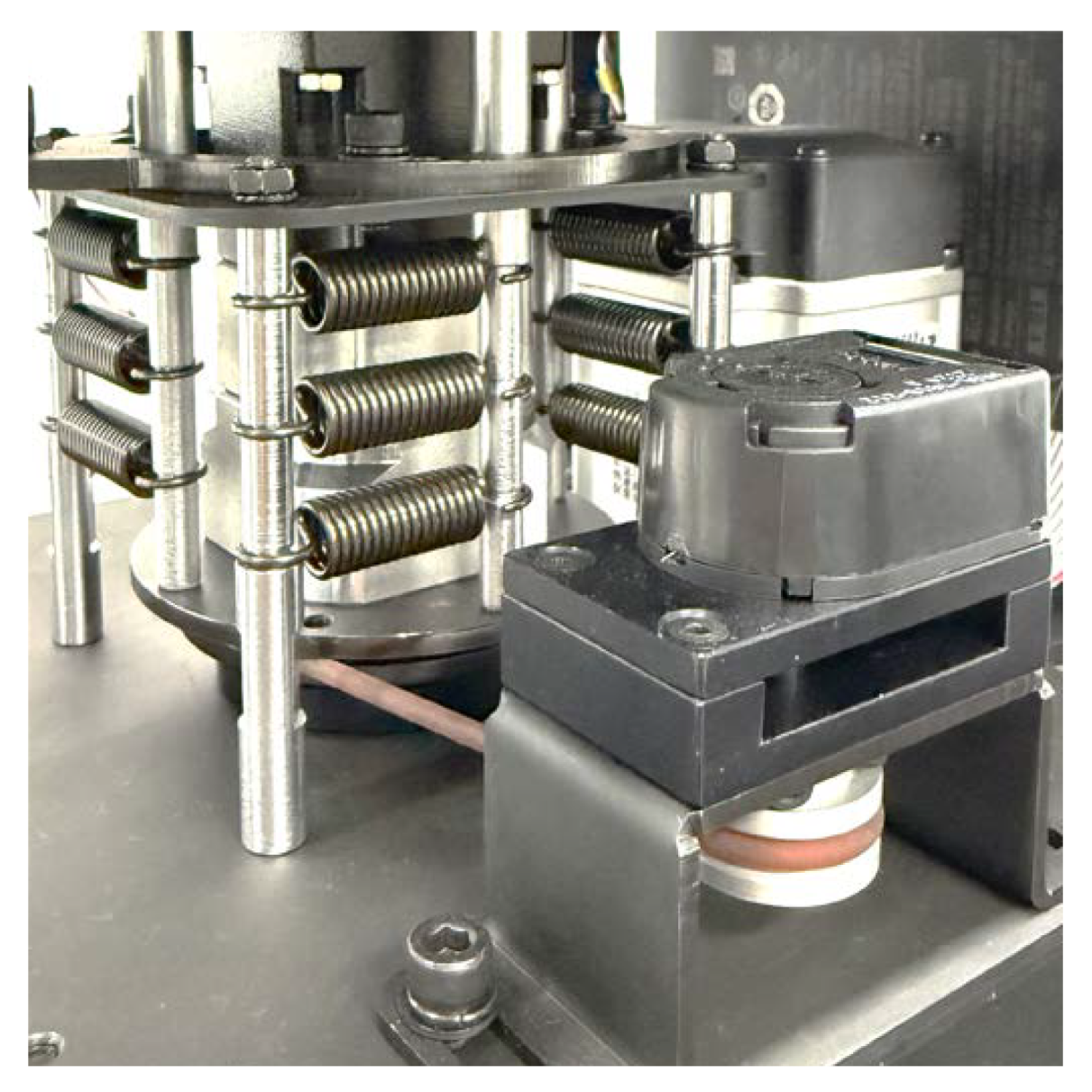
Figure 13 shows the fabricated TS-URM experimental setup. Each of the three layers contains four springs, resulting in a total of 12 tension springs generating the final torsional torque. This parallel configuration not only ensures that the target stiffness is reliably achieved but also distributes the applied load across multiple springs.
Figure 13.
The implemented TS-URM with installed tension springs.
3.2.3. Rotational Stiffness
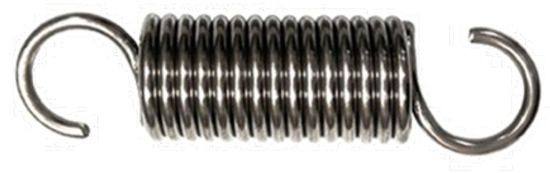
The final selected spring is the AWF10-40 model shown in Figure 14, and its key mechanical specifications are summarized in Table 3. This spring satisfies the required free-length condition (40 mm) of the proposed system and provides an appropriate linear stiffness constant to achieve the target rotational stiffness range.
Figure 14.
Selected tension spring (AWF10-40).
Table 3.
Mechanical properties of spring AWF10-40.
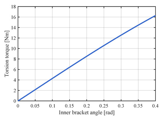
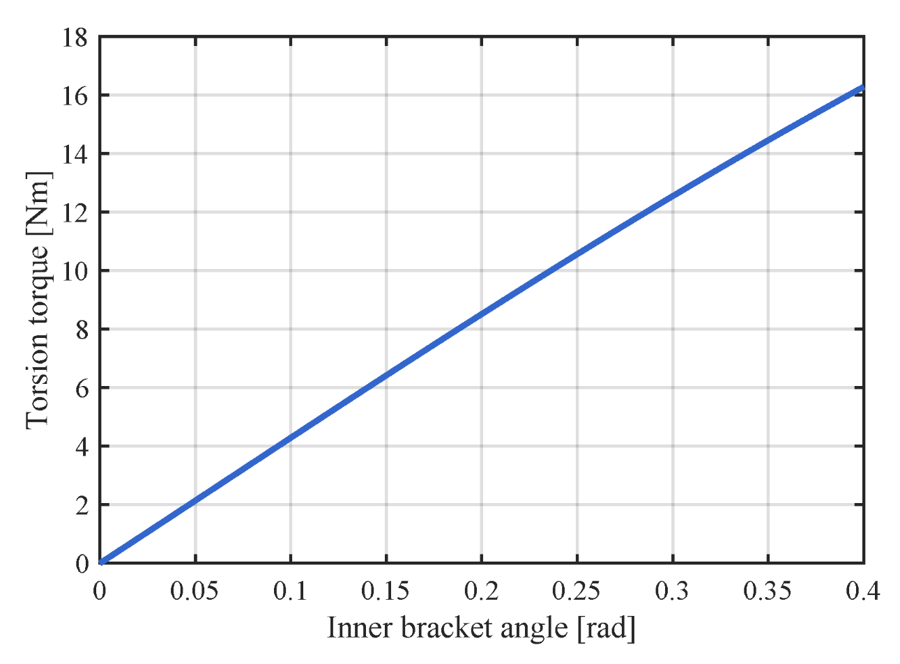
The rotational stiffness of the TS-URM was calculated based on the analytical model derived in Section 2. The effective rotational range of the inner bracket was assumed to be 0–0.4 rad, considering practical operating conditions. This range corresponds to the maximum rotation interval in which the mechanism can operate stably without spring interference, while also providing sufficient deformation for reliable force measurement resolution. The calculated torsional torque–rotation relationship within this range is shown in Figure 15. As observed, the stiffness exhibits a relatively linear trend over the entire interval, and the rotational stiffness is distributed within the range of approximately 42.5–42.9 Nm/rad. This is very close to the design target of 42 Nm/rad, and the variation in stiffness with respect to the rotation angle is limited.
Figure 15.
Theoretical rotational stiffness of the implemented TS-URM.
From a control perspective, assuming a constant stiffness simplifies controller design and stability analysis when modeling an SEA. Therefore, the average value of the calculated stiffness range, 42.75 Nm/rad, was adopted as the effective linear stiffness. This value is used as the nominal stiffness parameter in the subsequent control design.
3.3. Preload Design of Tension Spring
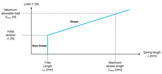
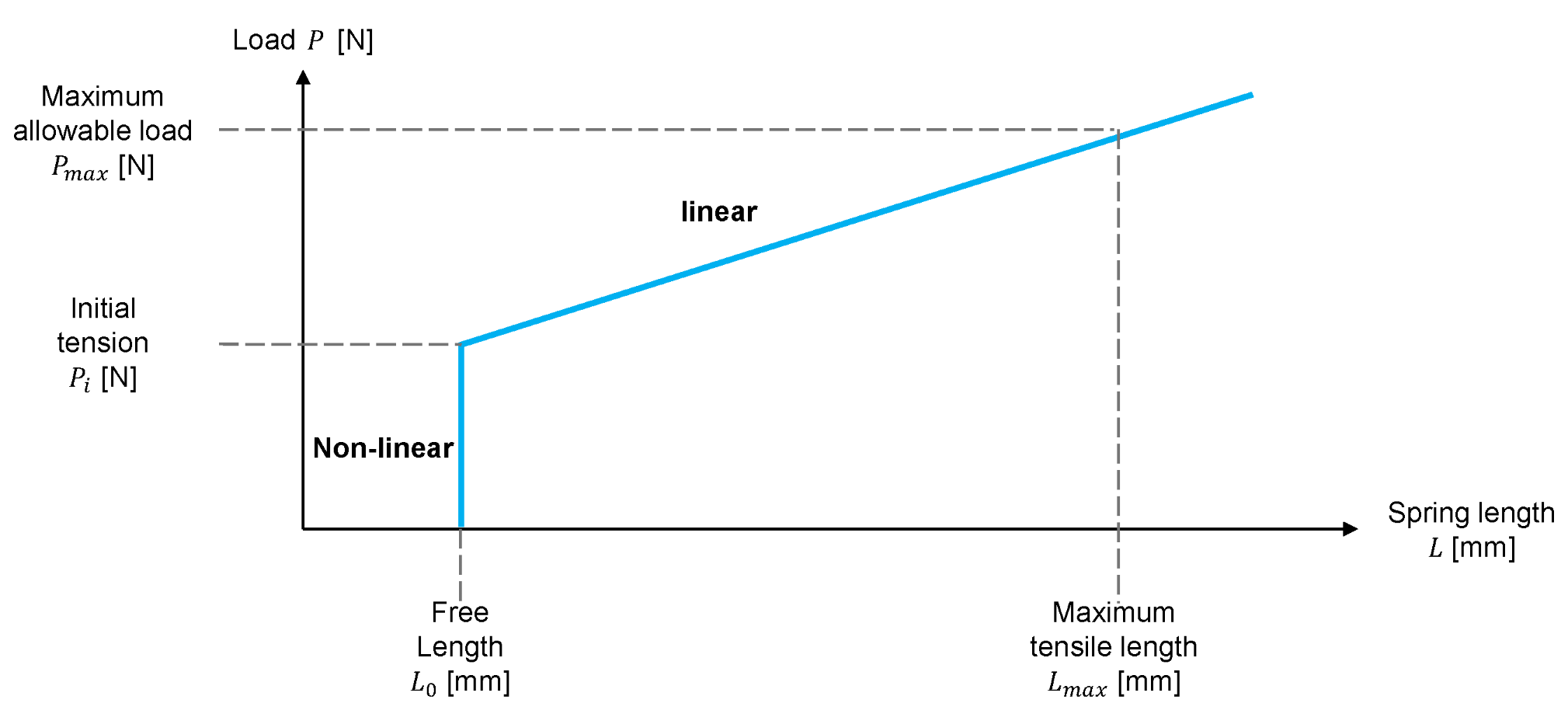
For practical implementation of the TS-URM in an actual system, the preload design of the tension springs must be carefully considered. Due to their structural characteristics, tension springs possess an inherent initial tension. The spring enters the linear elongation region only when the applied external force exceeds this initial tension.
As shown in Figure 16, in the region below the initial tension, the force–displacement relationship does not follow an ideal linear behavior, and the effective stiffness may appear unstable. If the TS-URM operates within this nonlinear region, the prediction error of the rotational stiffness may increase, leading to a reduction in force estimation accuracy. In a USEA configuration, ensuring linear behavior in the initial operating region is particularly important. This is because torque variations within small rotational angles are directly associated with force measurement resolution. Therefore, a preload strictly exceeding the initial tension of the spring ( N, Table 3) must be applied to mechanically displace the operating point into the linear force–displacement region prior to rotation, effectively eliminating the dead-zone nonlinearity from the onset of operation. This ensures that the simplified linear model Equation (7) remains valid across the full operating range without requiring the initial tension to be explicitly incorporated as a dynamic parameter in the real-time control model. The validity of this preload condition is experimentally verified in Section 4.2.
Figure 16.
Conceptual force–displacement characteristic of the tension spring.
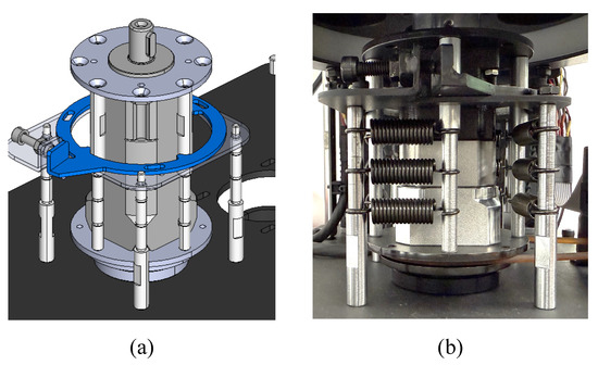
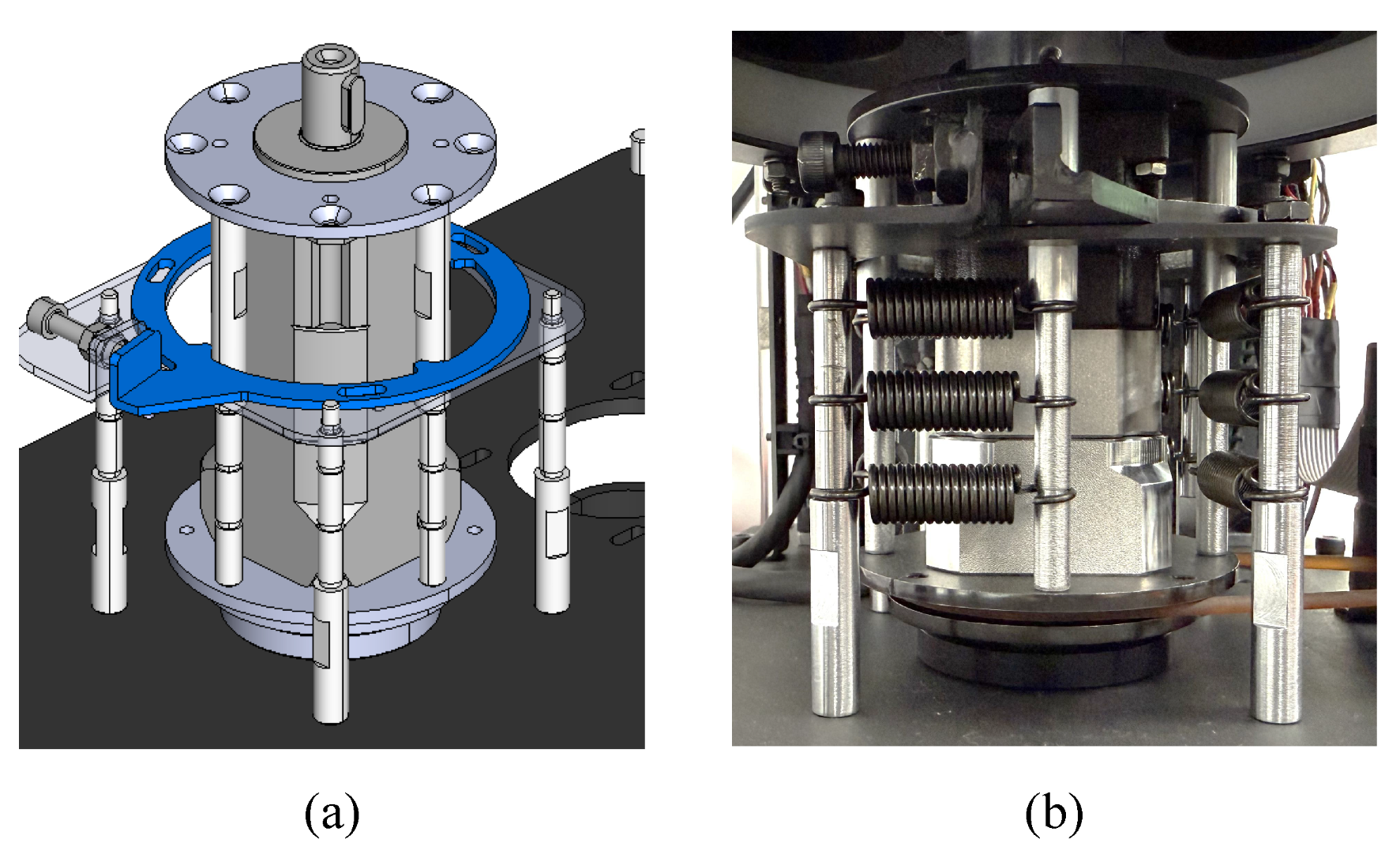
In the developed USEA, a mechanical adjustment mechanism was designed to regulate the preload, as shown in Figure 17. Adjustment bolts were incorporated at the fixed points of each spring, allowing fine-tuning of the initial tension by tightening or loosening the bolts.
Figure 17.
Preload adjustment components for the tension spring: (a) 3D CAD model (blue-highlighted components); (b) implementation in the actual device.
4. Experimental Validation
This section experimentally validates the performance of the developed USEA. The experiments were conducted with a focus on the following three aspects:
- Experimental verification of the rotational stiffness;
- Evaluation of stiffness variation according to preload conditions;
- Assessment of unidirectional force control performance using the USEA.
Through these experiments, the consistency between the analytical model and the implemented system is examined, and the effectiveness of the proposed structure in practical applications is demonstrated.
4.1. Rotational Stiffness Validation
In Section 3, the design procedure of the TS-URM was described, and the rotational stiffness calculated from the analytical model was presented in Figure 15. However, numerical calculations alone are insufficient to fully validate the actual mechanical behavior. Therefore, experimental verification was performed.
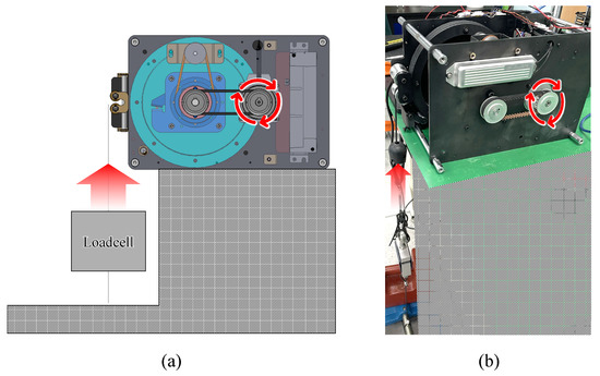
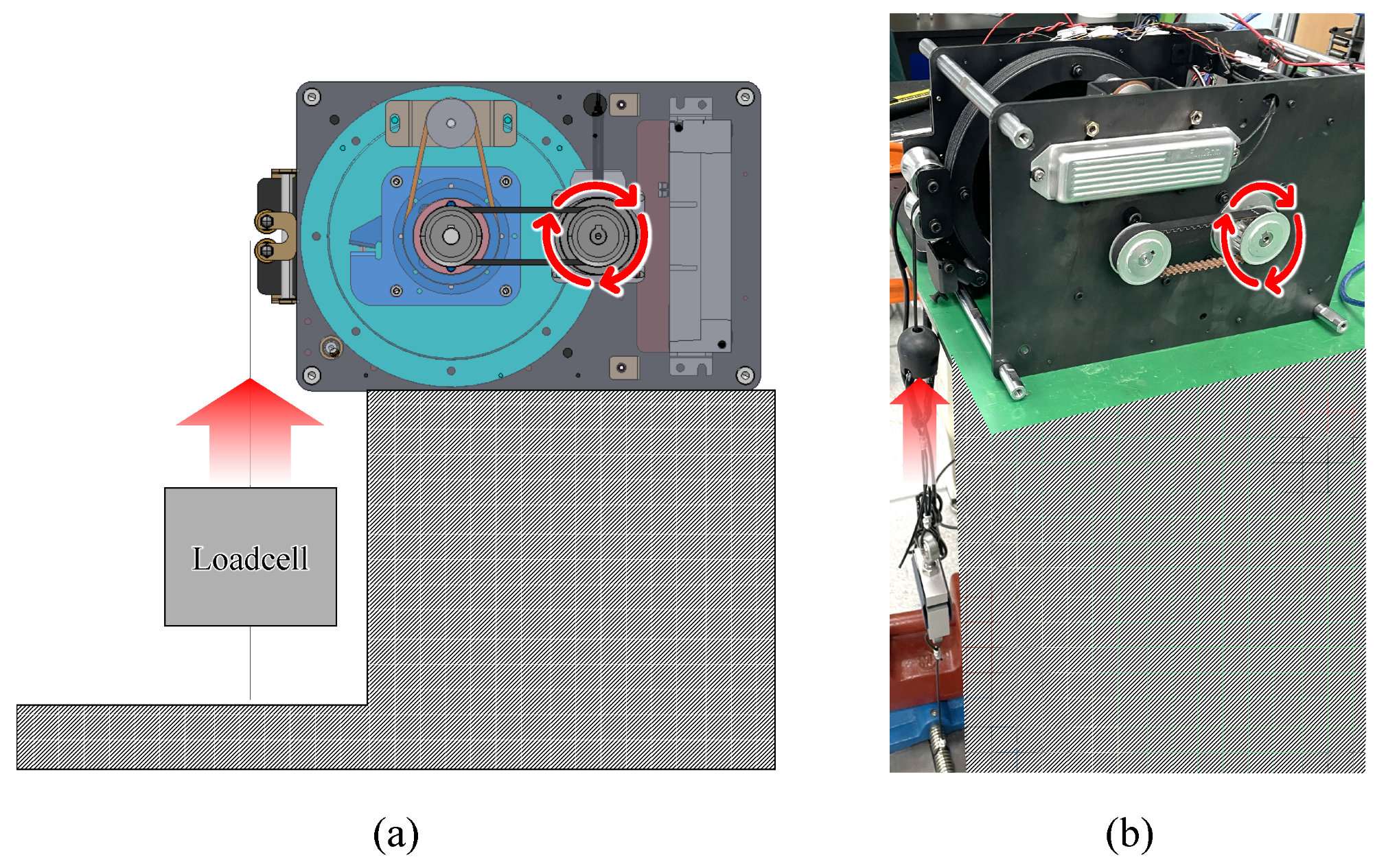
The experimental setup is shown in Figure 18. A load cell was connected to the output of the USEA. One end of the load cell was fixed to the ground, while the other end was attached to a load wheel. Since the radius of the load wheel is known, the linear force measured by the load cell can be converted into torque. The motor was controlled to perform unidirectional rotation in the counterclockwise direction, and the rotational angle of the inner bracket was measured using an encoder. Simultaneously, the output torque was recorded via the load cell.
Figure 18.
Experimental configuration for evaluating rotational stiffness: (a) conceptual configuration; (b) implemented experimental setup.
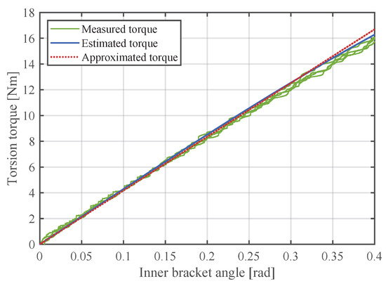
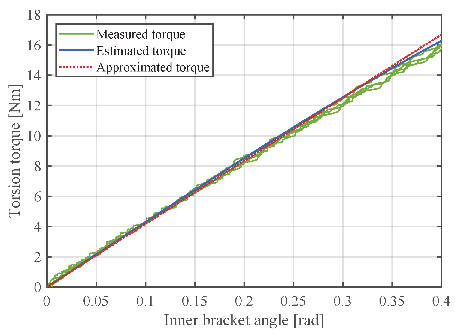
The experiment was repeated to assess measurement repeatability, and the results are presented in Figure 19. The green curve represents the measured torque, the blue curve indicates the estimated torque obtained from the analytical model, and the red curve corresponds to the approximated torque based on the nominal linear stiffness, which is derived as the mean value of the analytical stiffness range in Section 3.2.3.
Figure 19.
Experimental verification of the rotational stiffness coefficient (4 repeated trials).
In the rotational range of 0–0.2 rad, the three results exhibit very high agreement. This indicates that:
- The analytical model accurately reflects the actual mechanical behavior;
- The preload design effectively eliminates the initial nonlinear region;
- The designed stiffness is successfully realized in the implemented system.
As the rotation angle increases into the range of 0.2–0.4 rad, gradual deviations appear between the measured torque and the analytical predictions. In particular, within the interval of 0.35–0.4 rad, the rotational stiffness was observed as follows:
- Measured stiffness ≈ 30 Nm/rad;
- Estimated stiffness ≈ 35 Nm/rad;
- Approximated stiffness ≈ 42 Nm/rad.
These discrepancies can be attributed to several factors. (1) Elasticity and slight elongation of the output wire. Since the output of the USEA is transmitted through a wire-based structure, the inherent elasticity and friction of the wire may influence the measured torque. (2) Dynamic effects. Although the experiment was conducted under quasi-static conditions, minor inertial and frictional effects inevitably exist. Nevertheless, the overall torque–angle relationship remains within the target stiffness range across the entire rotational interval, confirming that the proposed structure satisfies the stiffness characteristics required for the USEA configuration. In particular, the high level of agreement between the analytical model and the experimental results over most of the design range (0–0.3 rad) indicates that the TS-URM-based USEA provides predictable stiffness characteristics during the design stage.
4.2. Preload Effect Evaluation
In Section 3.3, it was explained that preload is essential in the tension-spring-based TS-URM. In this subsection, the influence of preload on the actual rotational stiffness characteristics is experimentally evaluated.
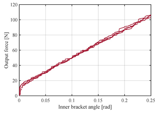
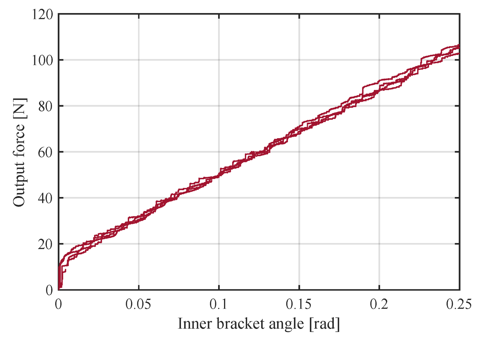
Figure 20 presents the force measured by the load cell as the inner bracket was rotated from the free-length condition of the spring to 0.25 rad. To ensure the reliability of the experiment, repeated trials were conducted under identical conditions, and the results demonstrated high repeatability.
Figure 20.
Experimental evaluation of preload characteristics for tension spring.
Near the free-length region, a nonlinear force–displacement relationship was observed due to the initial tension characteristic of the tension spring. This occurs because a stable internal tension distribution is not fully established until the spring is sufficiently elongated. In this region, the effective stiffness appears reduced, and the slope of the torque–rotation relationship is not constant. However, when an appropriate preload is applied, the operating point of the spring shifts into the linear region, allowing a consistent stiffness to be maintained over the entire operating range. By gradually increasing the preload and comparing the resulting rotational stiffness characteristics, it was confirmed that applying an initial tension of approximately 17–19 N eliminates the nonlinear region and maintains stable linear behavior within the 0–0.25 rad range.
This preload range was selected to simultaneously satisfy the following conditions:
- Elimination of the initial nonlinear region;
- Prevention of excessive preload that could reduce spring fatigue life;
- Maintenance of consistent stiffness over the full operating range.
Accordingly, 17–19 N was defined as the minimum effective preload range in this study. This confirms that appropriate preload is a necessary condition for the TS-URM to reliably reproduce the designed stiffness characteristics in practical implementation.
4.3. Force Control Performance
To verify the practical effectiveness of the developed USEA, unidirectional force control experiments were conducted. The USEA structure can be applied to systems requiring pulling-type actuation, such as exercise equipment and tension-control devices. In such applications, it is essential to precisely regulate continuous force in a single direction.
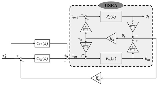
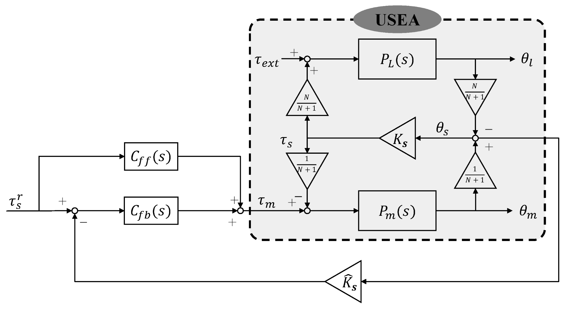
In this study, a spring-feedback-based transmission torque control strategy, commonly used in SEA systems, was implemented. As shown in Figure 21, the transmitted torque was calculated from the rotational deformation of the inner bracket and used as the feedback signal, where denotes the reference torque, is the motor torque, is the external torque, and are the feedforward and feedback controllers, and represent the motor and load dynamics, is the rotational stiffness, is the estimated stiffness, N is the gear ratio, and , , are the motor, load, and spring angles, respectively.
Figure 21.
Control block diagram for evaluating the force control performance of the developed module.
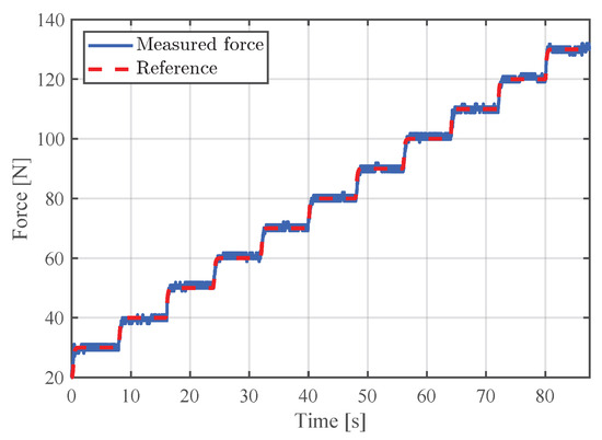
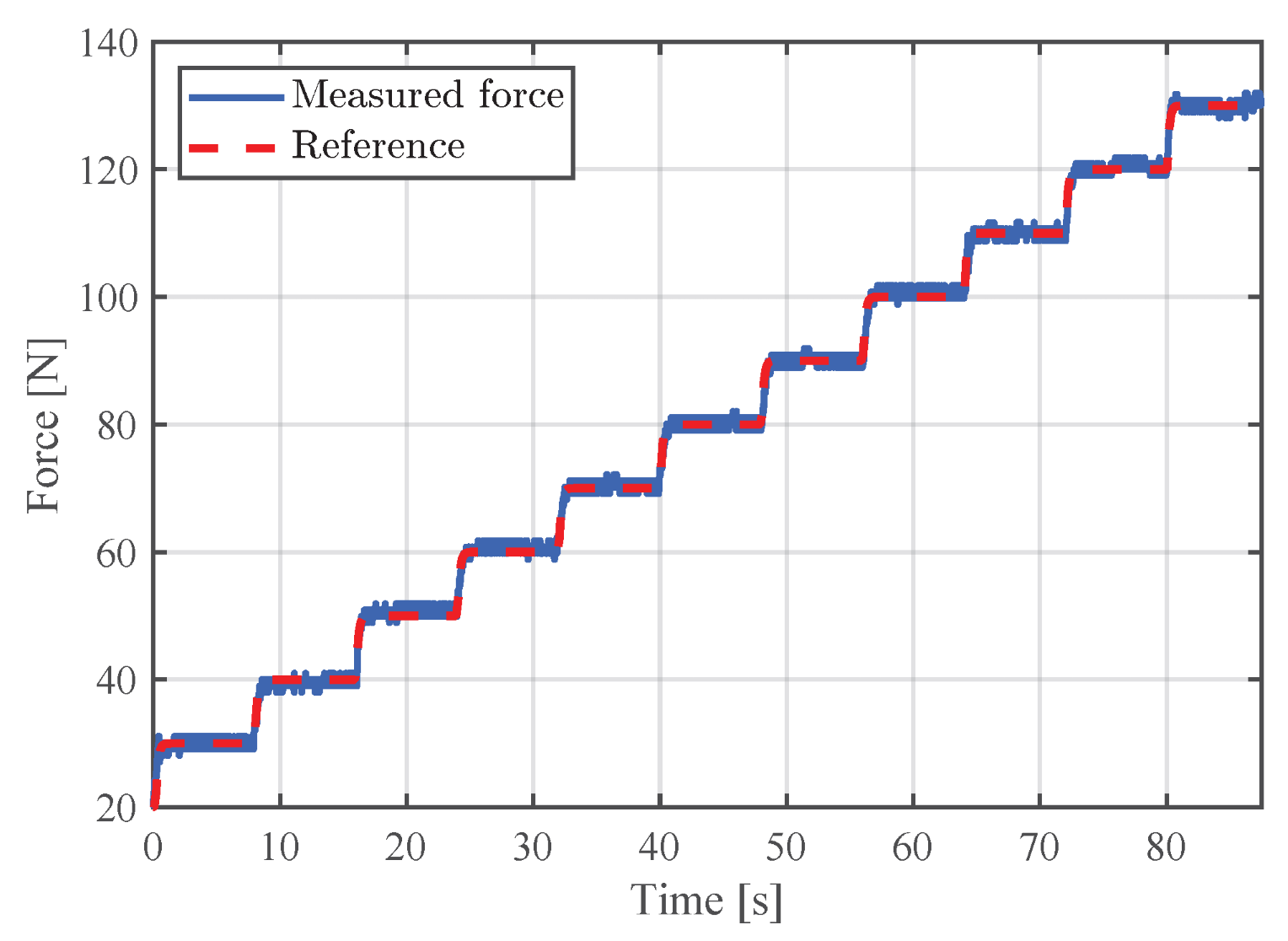
To validate the effectiveness of the TS-URM, a gradually increasing unidirectional force command was applied. Considering applications in exercise equipment, step reference inputs in the range of 20–130 N were imposed.
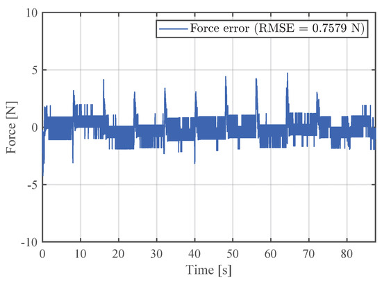
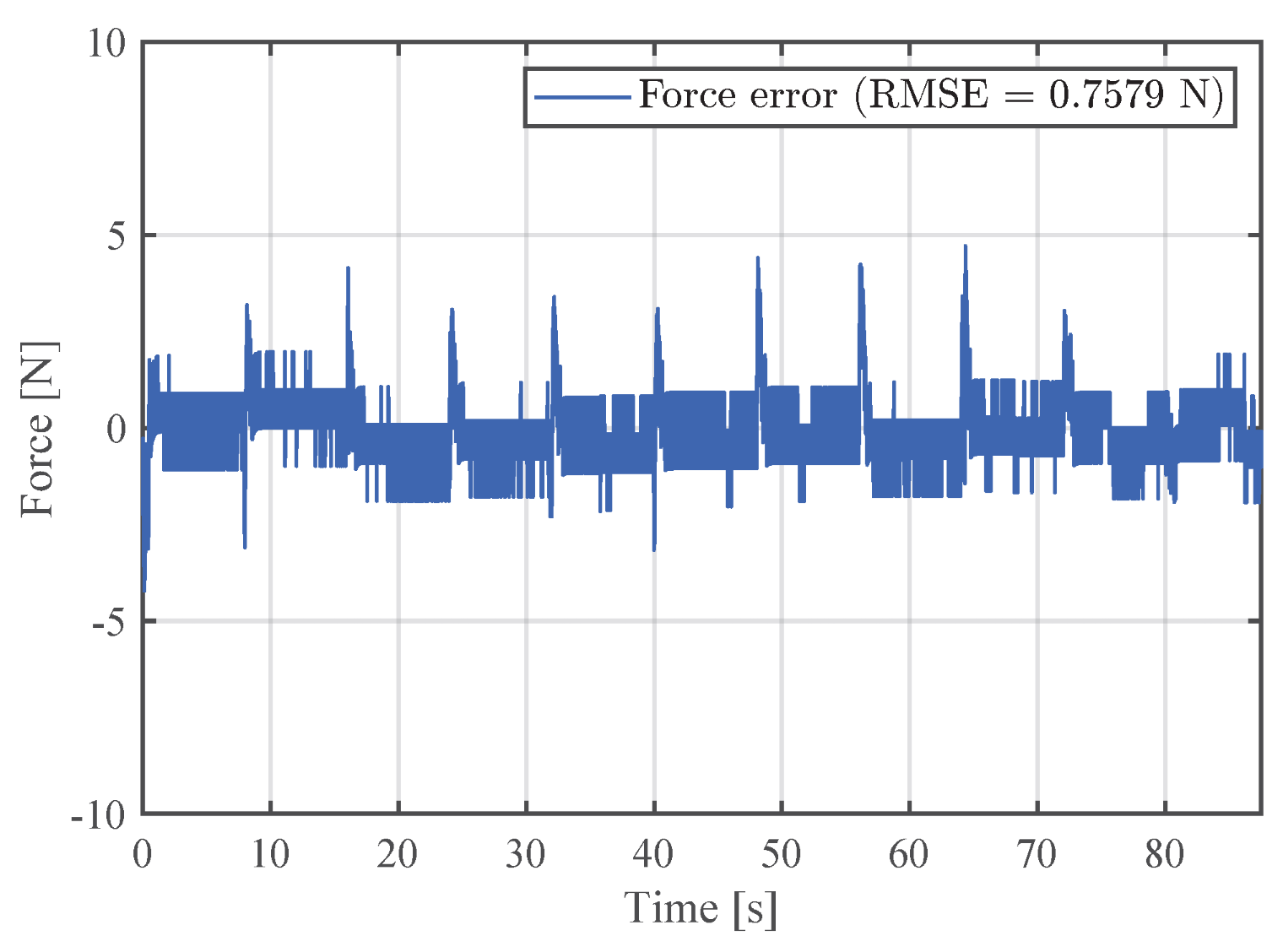
The experimental results are presented in Figure 22. The output force stably tracked the reference even under high-load conditions, and the maximum steady-state error was confirmed to be within 1 N. The corresponding force tracking error is presented in Figure 23, with a Root Mean Square Error (RMSE) of 0.7579 N, corresponding to less than 1% of the full operating range.
Figure 22.
Experimental results of force tracking performance under step reference inputs.
Figure 23.
Force tracking error under step reference inputs (RMSE = 0.7579 N).
In particular, stable force tracking performance was maintained even in the high-load region (above 130 N), and no oscillatory or divergent behavior was observed. This indicates that:
- The TS-URM-based rotational stiffness is reliably realized in an actual control environment;
- The preload design effectively eliminates the initial nonlinear region;
- The USEA structure maintains sufficient stiffness stability even under high-load conditions.
These results confirm that the proposed TS-URM design provides rotational stiffness consistent with the analytical model and that the integrated USEA achieves precise performance in unidirectional force control applications. These characteristics suggest that the developed module can be effectively utilized as an application platform that maintains a constant force during continuous human interaction (Video S1).
5. Discussion
5.1. Validation of the Analytical Model
The experimental results demonstrate that the proposed analytical model accurately predicts the torque–angle relationship within the primary operating range (0–0.3 rad). The close agreement between the analytical, estimated, and measured torque values in this region confirms that the geometric formulation effectively captures the essential kinematic relationship between spring elongation and rotational deformation.
However, deviations become noticeable as the rotation approaches the upper bound (0.35–0.4 rad). Several factors may explain this discrepancy. First, the analytical model assumes ideal rigid brackets and neglects secondary compliance in the output transmission components, including wire elasticity and minor bracket deformation. Second, quasi-static assumptions were used in the model derivation, while small dynamic and frictional effects may still be present in the experimental setup. Third, manufacturing tolerances and slight variations in initial tension among springs can introduce asymmetry in load sharing.
Despite these factors, the overall stiffness remains within the intended design range. This indicates that the analytical model provides sufficiently accurate predictability for design-stage stiffness estimation, which is a key advantage over purely FEM-based structural torsional elastomer approaches.
5.2. Structural Efficiency of the Unidirectional Mechanism
A major motivation for this study is the structural inefficiency of conventional bidirectional SEA configurations in applications that primarily require force generation in one direction. In bidirectional tension-spring-based SEAs, elastic deformation is symmetrically available in both rotational directions. However, in pulling-type systems, only one half of this deformation range is effectively utilized.
In contrast, the proposed TS-URM is structurally optimized for unidirectional torque transmission. The entire effective deformation range contributes directly to usable torque generation. From a volumetric efficiency perspective, this increases the torque utilization ratio within the same geometric envelope.
Moreover, because springs are arranged symmetrically only for the active direction, unnecessary structural redundancy in the inactive direction is avoided. This leads to improved space utilization and reduced structural complexity compared to bidirectional counterparts designed for symmetric compliance.
5.3. Comparison with Existing Rotary Stiffness Realization Methods
Compared with structural torsional elastomer approaches, the proposed mechanism offers enhanced analytical predictability. In planar torsional springs with complex geometries, stiffness is strongly coupled with distributed beam deformation and often requires FEM-based parameter optimization. In contrast, the TS-URM enables direct derivation of the torque–angle relationship from geometric parameters, allowing closed-form stiffness estimation during the design phase.
Relative to compression spring array mechanisms, the use of tension springs eliminates buckling risk and reduces the need for additional guiding structures. This simplifies mechanical design and minimizes friction-induced nonlinearities. Furthermore, stiffness tuning can be achieved through straightforward adjustment of spring constant, installation angle, or the number of springs.
Compared to existing bidirectional tension-spring SEA configurations, the key distinction lies in directional optimization. The proposed design intentionally exploits the unilateral force transmission characteristic of tension springs, resulting in improved deformation efficiency for pulling-type applications. This directional optimization also yields a measurable reduction in the number of required elastic elements, directly translating into improvements in system mass and spatial occupancy.
To further quantify the structural efficiency of the proposed unidirectional design, a spring-level comparison was performed based on the implemented USEA. The proposed design employs 12 tension springs (AWF10-40) with a total mass of 81.6 g and a total volume of 37,699 mm3. A symmetric bidirectional configuration of equivalent rotational stiffness would require 24 springs, resulting in a total mass of 163.2 g and a total volume of 75,398 mm3, representing a 50% reduction in both spring mass and volumetric occupancy through unidirectional optimization.
5.4. Design Implications and Parameter Sensitivity
The analytical derivation clarifies the influence of design parameters on rotational stiffness characteristics. Among these parameters, the installation angle plays a critical role in determining stiffness linearity. Smaller installation angles result in a torque–angle relationship that is closer to linear behavior, while larger angles increase geometric nonlinearity due to the trigonometric coupling between spring elongation and bracket rotation.
Additionally, increasing the number of springs per layer increases overall stiffness but reduces the allowable rotational range due to geometric interference. Therefore, a multilayer stacking strategy is more advantageous than increasing the number of springs within a single plane when both stiffness and deformation range must be preserved.
The preload level also significantly influences initial linearity. Without sufficient preload, the inherent initial tension characteristics of tension springs introduce nonlinear behavior in the small-angle region. The proposed preload adjustment mechanism effectively shifts the operating point into the linear region, improving force estimation reliability.
These findings provide practical design guidelines for engineers implementing tension-spring-based rotational stiffness mechanisms.
5.5. Limitations and Future Work
Several limitations should be acknowledged. First, the present study focuses primarily on quasi-static stiffness characterization. Dynamic stiffness variation, damping effects, and high-frequency response characteristics were not investigated in detail. Second, the long-term durability and fatigue behavior of the tension springs under cyclic loading remain to be evaluated. Third, the wire-based output transmission may introduce additional compliance that should be incorporated into future system-level modeling.
Future work will focus on dynamic modeling of the proposed mechanism, integration with high-bandwidth control architectures, and long-term reliability testing under cyclic loading conditions. Higher-order system modeling incorporating secondary compliance sources will be pursued to improve force estimation accuracy at higher operating frequencies. Additionally, the application of the proposed USEA in real-world tension control systems will be explored.
6. Conclusions
This study proposed a TS-URM and its implementation in a wire-driven USEA. Unlike conventional bidirectional SEA configurations, the proposed mechanism is structurally optimized for unidirectional torque transmission, improving deformation utilization efficiency in pulling-type applications.
An analytical model was derived to describe the geometric relationship between spring elongation and rotational deformation, enabling explicit formulation of the torque–angle relationship. The effects of key design parameters, particularly the installation angle, on stiffness linearity were systematically analyzed. Based on this framework, a multilayer spring configuration was optimized to achieve the target rotational stiffness of approximately 42 Nm/rad.
A preload adjustment mechanism was incorporated to eliminate nonlinear behavior in the initial operating region. Experimental results confirmed the validity of the analytical model and demonstrated stable unidirectional force control up to 130 N, with steady-state errors within 1 N.
The proposed mechanism provides analytically predictable stiffness characteristics, structural simplicity, and improved torque utilization for unidirectional force generation systems. Future work will address dynamic characterization and long-term durability under cyclic loading.
Supplementary Materials
The following supporting information can be downloaded at: https://www.mdpi.com/article/10.3390/act15040180/s1. Video S1: Demonstration of the developed USEA as a pulling-type force control platform during continuous human interaction.
Author Contributions
Conceptualization, C.L.; methodology, C.L.; software, J.L.; validation, J.L.; formal analysis, J.L. and D.K.; investigation, J.L.; resources, C.L.; data curation, D.K.; writing—original draft preparation, D.K.; writing—review and editing, C.L.; visualization, D.K.; supervision, C.L.; project administration, C.L.; funding acquisition, C.L. All authors have read and agreed to the published version of the manuscript.
Funding
This work was supported by the 2022 Yeungnam University Research Grant.
Institutional Review Board Statement
Not applicable.
Informed Consent Statement
Not applicable.
Data Availability Statement
The original contributions presented in the study are included in the article; further inquiries can be directed to the corresponding author.
Conflicts of Interest
Jiho Lee was employed by SL Corporation. Chan Lee serves as CEO of Hyperdyne Inc. The remaining authors declare that the research was conducted in the absence of any commercial or financial relationships that could be construed as a potential conflict of interest.
References
- Pratt, G.A.; Williamson, M.M. Series elastic actuators. In Proceedings of the 1995 IEEE/RSJ International Conference on Intelligent Robots and Systems. Human Robot Interaction and Cooperative Robots, Pittsburgh, PA, USA, 5–9 August 1995; IEEE: Piscataway, NJ, USA, 1995; Volume 1, pp. 399–406. [Google Scholar]
- Choi, W.; Oh, S. Ball Screw-Based Series Elastic Actuator-Driven Suspension and Cabin Heave Acceleration Vibration Suppression Control for Vehicle Ride Comfort Enhancement. IEEE/ASME Trans. Mechatron. 2025, 30, 3008–3018. [Google Scholar] [CrossRef] [Scilit]
- Cheon, D.; Nam, K.; Oh, S. Design and robust control of a precise torque controllable steering module for steer-by-wire systems. IEEE Trans. Ind. Electron. 2022, 69, 13245–13254. [Google Scholar] [CrossRef] [Scilit]
- Jarrett, C.; McDaid, A. Modeling and feasibility of an elastomer-based series elastic actuator as a haptic interaction sensor for exoskeleton robotics. IEEE/ASME Trans. Mechatron. 2019, 24, 1325–1333. [Google Scholar] [CrossRef] [Scilit]
- Choi, S.; Kim, J.; Ko, C.; Kong, K. Flexi-SEA: Flexible-Shaft-Driven Series Elastic Actuator for Wearable Robots. IEEE/ASME Trans. Mechatron. 2025, 30, 6882–6892. [Google Scholar] [CrossRef] [Scilit]
- Yu, H.; Huang, S.; Chen, G.; Pan, Y.; Guo, Z. Human–robot interaction control of rehabilitation robots with series elastic actuators. IEEE Trans. Robot. 2015, 31, 1089–1100. [Google Scholar] [CrossRef] [Scilit]
- Ghidini, S.; Beschi, M.; Pedrocchi, N. A robust linear control strategy to enhance damping of a series elastic actuator on a collaborative robot. J. Intell. Robot. Syst. 2020, 98, 627–641. [Google Scholar] [CrossRef] [Scilit]
- Roozing, W.; Malzahn, J.; Kashiri, N.; Caldwell, D.G.; Tsagarakis, N.G. On the stiffness selection for torque-controlled series-elastic actuators. IEEE Robot. Autom. Lett. 2017, 2, 2255–2262. [Google Scholar] [CrossRef] [Scilit]
- Pagliarani, N.; Arleo, L.; Luca, G.D.; Pozzi, J.; Cianchetti, M. Variable stiffness structure inspired by seashells. Smart Mater. Struct. 2024, 33, 025004. [Google Scholar] [CrossRef] [Scilit]
- Carpino, G.; Accoto, D.; Sergi, F.; Luigi Tagliamonte, N.; Guglielmelli, E. A novel compact torsional spring for series elastic actuators for assistive wearable robots. J. Mech. Des. 2012, 134, 121002. [Google Scholar] [CrossRef] [Scilit]
- Wang, Y.; Chen, Y.; Chen, K.; Wu, Y.; Huang, Y. A flat torsional spring with corrugated flexible units for series elastic actuators. In Proceedings of the 2017 2nd International Conference on Advanced Robotics and Mechatronics (ICARM), Hefei and Tai’an, China, 27–31 August 2017; IEEE: Piscataway, NJ, USA, 2017; pp. 138–143. [Google Scholar]
- Tsagarakis, N.G.; Laffranchi, M.; Vanderborght, B.; Caldwell, D.G. A compact soft actuator unit for small scale human friendly robots. In Proceedings of the 2009 IEEE International Conference on Robotics and Automation, Kobe, Japan, 12–17 May 2009; IEEE: Piscataway, NJ, USA, 2009; pp. 4356–4362. [Google Scholar]
- de Gea Fernández, J.; Yu, B.; Bargsten, V.; Zipper, M.; Sprengel, H. Design, modelling and control of novel series-elastic actuators for industrial robots. Actuators 2020, 9, 6. [Google Scholar] [CrossRef] [Scilit]
- Qian, Y.; Han, S.; Aguirre-Ollinger, G.; Fu, C.; Yu, H. Design, modeling, and control of a reconfigurable rotary series elastic actuator with nonlinear stiffness for assistive robots. Mechatronics 2022, 86, 102872. [Google Scholar] [CrossRef] [Scilit]
- Zhao, W.; Liao, J.; Qian, W.; Yu, H.; Guo, Z. A novel design of series elastic actuator using tensile springs array. Mech. Mach. Theory 2024, 192, 105541. [Google Scholar] [CrossRef] [Scilit]
- Park, J.; Kim, D.H.; Hyung, S.; Shin, G.; Kim, Y.G.; Kim, S.H.; Yoon, C.; Ko, S.; Hahm, K.; Lee, M. Design of a cable driven wearable fitness device for upper limb exercise. In Proceedings of the 2023 IEEE/RSJ International Conference on Intelligent Robots and Systems (IROS), Detroit, Michigan, USA, 1–5 October 2023; IEEE: Piscataway, NJ, USA, 2023; pp. 6456–6461. [Google Scholar]
- Martin, C.; Zhao, Q.; Patel, A.; Velasquez, E.; Chen, D.; Li, W. A review of advanced Roll-to-Roll manufacturing: System modeling and control. J. Manuf. Sci. Eng. 2025, 147, 041004. [Google Scholar] [CrossRef] [Scilit]
- Kosari, S.N.; Ramadurai, S.; Chizeck, H.J.; Hannaford, B. Control and tension estimation of a cable driven mechanism under different tensions. In Proceedings of the International Design Engineering Technical Conferences and Computers and Information in Engineering Conference; American Society of Mechanical Engineers: New York, NY, USA, 2013; Volume 55935, p. V06AT07A077. [Google Scholar]
- Zhang, B.; Shang, W.; Cong, S.; Li, Z. Dual-loop dynamic control of cable-driven parallel robots without online tension distribution. IEEE Trans. Syst. Man, Cybern. Syst. 2022, 52, 6555–6568. [Google Scholar] [CrossRef] [Scilit]
- Caverly, R.J.; Forbes, J.R. Flexible cable-driven parallel manipulator control: Maintaining positive cable tensions. IEEE Trans. Control. Syst. Technol. 2017, 26, 1874–1883. [Google Scholar] [CrossRef]

Disclaimer/Publisher’s Note: The statements, opinions and data contained in all publications are solely those of the individual author(s) and contributor(s) and not of MDPI and/or the editor(s). MDPI and/or the editor(s) disclaim responsibility for any injury to people or property resulting from any ideas, methods, instructions or products referred to in the content. |
© 2026 by the authors. Licensee MDPI, Basel, Switzerland. This article is an open access article distributed under the terms and conditions of the Creative Commons Attribution (CC BY) license.