Abstract
This paper presents a novel methodology for minimizing power losses in brushless DC (BLDC) motors through the implementation of adaptive flux control techniques. Conventional motor control strategies, such as direct torque control (DTC), typically employ fixed flux values, which often result in suboptimal performance, particularly under dynamic load and speed variations. To mitigate this inherent limitation, two adaptive flux control methods are introduced: incremental conductance (IncCond) and fuzzy logic. These proposed strategies facilitate real-time dynamic adjustment of the stator flux, thereby optimizing motor performance and significantly enhancing system efficiency. Experimental validation confirms the efficacy of these adaptive techniques, demonstrating substantial improvements in power loss reduction and overall efficiency when compared to traditional fixed flux control strategies. Notably, the fuzzy logic control strategy achieves the highest efficiency, registering a system efficiency of %, which surpasses both the incremental conductance method and conventional fixed flux control. These findings underscore the considerable potential of adaptive flux control in applications where energy efficiency is paramount, including electric vehicles and renewable energy-driven systems.
1. Introduction
BLDC motors are widely used in modern drive systems due to their high efficiency, compact size, high torque-to-weight ratio, and low maintenance requirements. They play a critical role in a broad range of applications, including electric vehicles, robotics, industrial automation, HVAC systems, and renewable energy systems such as wind turbines and solar water pumps. Their inherent advantages over brushed DC and induction motors make them ideal for high-performance and energy-sensitive applications.
Although BLDC motors are widely recognized for their high efficiency, power losses resulting from non-optimal flux control remain a significant concern, particularly in real-time applications with stringent energy-saving requirements. To mitigate these losses and enhance drive performance, the implementation of adaptive flux control strategies is imperative, especially under varying load and speed conditions.
Minimizing power losses in BLDC motors remains a central focus of research, particularly through the use of adaptive flux control strategies such as fuzzy logic controllers (FLCs) and IncCond. FLCs have proven highly effective in dealing with nonlinearities and system uncertainties. Ref. [] demonstrated that fuzzy-based speed controllers significantly reduce overshoot and torque ripple while halving the settling time compared to conventional PID methods. Similarly, ref. [] confirmed that fuzzy logic, when combined with power factor correction, leads to reduced rise time and enhanced dynamic performance. Hybrid control approaches, such as the one proposed by [], merge the benefits of digital adaptive PID with fuzzy logic to achieve superior torque regulation and disturbance rejection.
Incremental conductance, while traditionally applied in Maximum Power Point Tracking (MPPT) in photovoltaic systems, is emerging as a viable method for real-time flux adaptation in BLDC motors. Ref. [] has successfully applied IncCond to BLDC pump systems, showing improved efficiency under dynamic operating conditions. An ANFIS-enhanced IncCond-based control scheme is explored in [], reporting significant improvements in total harmonic distortion and system responsiveness.
T–S fuzzy PI controllers in buck-boost converters for enhanced performance are presented in [], while studies such as [,] confirm the benefits of fuzzy-PID and sliding-mode methods in regulating BLDC motor dynamics. Furthermore, the use of IncCond in FPGA-based systems for renewable energy-driven BLDC control has been investigated by [].
In the area of sensorless estimation and control, a recent study detailed advancements using sliding-mode observers, Kalman filters, and deep learning-based zero-shot estimation for flux and speed control []. These developments align with the growing need for robust and intelligent motor control systems in embedded and real-time environments.
A commutation point optimization method is presented for sensorless BLDC motors that reduces commutation error and improves efficiency by compensating for the phase difference between back EMF and phase current. Ref. [] proposes a commutation point optimization method for sensorless BLDC motors that accurately compensates for commutation errors by analyzing the phase difference between back EMF and phase current, improving efficiency. The study presents a new switching technique to minimize losses in a trapezoidal brushless DC motor drive, demonstrating superior performance in terms of torque ripple, current ripple, and overall efficiency []. A study compares two PWM techniques for BLDC motor control, with one technique showing superior performance in minimizing torque ripple, DC current ripple, and losses []. Machine learning models for sensorless estimation of BLDC motor winding temperature are proposed in [], achieving high accuracy with a mean absolute percentage error below 4.5% and demonstrating the viability of eliminating physical temperature sensors. A study in [] presents an energy-efficient BLDC motor optimized for a centrifugal monoset pump using Grey Wolf Optimization (GWO), demonstrating a 6% increase in efficiency validated through 3D finite element analysis.
Applying a tilt integral derivative (TID) controller to BLDC motors significantly enhances real-time speed control, torque and current stability, and overall system efficiency in electric vehicle applications []. An improved robust deadbeat predictive sensorless current control scheme is proposed for permanent magnet synchronous motors (PMSMs), employing an enhanced super-twisting sliding-mode observer to simultaneously estimate back electromotive force (EMF), inductance, and flux linkage. This unified observer effectively mitigates the impact of parameter mismatches, enhancing overall system robustness []. An improved adaptive fractional-order sliding mode control (AFOSMC) system is proposed for PMSMs, integrating a fractional-order sliding mode disturbance observer to enhance robustness, anti-interference capabilities, and overall dynamic and steady-state performance []. A novel four-point trajectory tracking control method for PMSMs is proposed to enhance dynamic response speed and steady-state efficiency across the full-speed range by adaptively adjusting current trajectories [].
A study introduced a novel adaptive flux observer for direct torque and flux control (DTFC) of permanent magnet synchronous motor (PMSM) drives, employing an online loss minimization algorithm to estimate the air-gap flux for optimal efficiency across various operating conditions []. A multi-objective optimization approach for PI controllers in BLDC motor speed control for electric vehicles is developed, integrating constrained swarm-based algorithms and real-time road gradient data to significantly improve speed control precision and reduce energy consumption []. An adaptive PID controller integrated with direct torque control (DTC) for fuel cell-fed BLDC motor drives is proposed, demonstrating effective regulation of torque and speed while addressing nonlinearity, parameter fluctuations, and load transient issues in industrial applications [].
Despite these advancements, direct experimental comparisons between fuzzy logic and IncCond methods for flux control in BLDC motors, specifically with respect to real-time power loss minimization, remain limited. This paper addresses this gap by providing a comparative experimental study using a Hardware-in-the-Loop (HIL) setup, demonstrating the superior efficiency and adaptability of fuzzy control, while also validating the promising performance of the IncCond method.
This paper investigates two adaptive flux control strategies for BLDC motors, each aiming to overcome the limitations of fixed flux control by dynamically adjusting the stator flux reference in real time. The first strategy applies the incremental conductance (IncCond) method, originally developed for photovoltaic MPPT, to refine the flux reference according to instantaneous system operating conditions. The second strategy employs a fuzzy logic controller, specifically a Mamdani-type fuzzy inference system, which incorporates expert knowledge to manage system nonlinearities and uncertainties by adjusting the stator flux based on motor speed and load torque. Each method is implemented and evaluated independently to assess its effectiveness in improving torque performance, reducing power losses, and enhancing overall system efficiency, particularly in applications such as electric vehicles and renewable energy systems.
This study employs a 100 W BLDC motor with well-characterized internal parameters, enabling detailed analysis and accurate validation of the proposed adaptive flux control strategies. Although the absolute power losses in such low-power systems are relatively small, their proportionate impact on overall efficiency is considerable, making the setup well-suited for comparative evaluation. Moreover, the control methods developed and tested in this work are designed to be scalable and applicable to higher-power systems, including those used in electric vehicles and industrial motor drives, where efficiency optimization remains a critical objective.
The paper is structured as follows: Section 2 introduces the mathematical model of the BLDC motor. Then, the proposed adaptation flux control technique is discussed in Section 3, while Section 4 presents the power losses. Section 5 discusses the experimental results. Finally, Section 6 concludes the paper by summarizing the key findings and future directions.
2. Mathematical Model of the BLDC Motor
The state-space approach is a fundamental tool in modern control theory for modeling and analyzing dynamic systems []. This method provides a compact mathematical framework applicable to both linear and nonlinear control strategies, making it essential for designing high-performance motor controllers.
This study considers a three-phase BLDC motor controlled via a full-bridge inverter operating in sinusoidal conduction mode, where at any instant, all three phases conduct current simultaneously with sinusoidal waveforms synchronized to the rotor position. To simplify the analysis, the following assumptions are made: the magnetic circuit is unsaturated, the phase resistances remain constant and are unaffected by temperature variations, and the self-inductances do not vary with rotor position. This modeling approach enhances efficiency, ensures smoother torque, and simplifies commutation. The system dynamics are represented in state-space form as:
where are the line voltages, the back-EMFs, R the phase resistance, L the phase inductance, J the rotor moment of inertia, B the friction coefficient, the electromagnetic torque, the load torque, the rotor speed, the rotor position, and the phase currents.
To facilitate control implementation, the Clarke transformation maps the three-phase () voltages, currents, and back-EMFs into a two-phase () stationary reference frame:
The flux linkages in the frame are given by:
with the estimated flux magnitude:
The electromagnetic torque is expressed as:
where P is the number of pole pairs. The motor parameters used in this study are listed in Table 1. These values are based on a standard BLDC motor model available in the MATLAB/Simulink library R2024b, commonly used for academic and validation purposes.

Table 1.
BLDC motor parameters.
In this paper, a DTC strategy for the BLDC motor is implemented using a predefined switching pattern presented in Equation (6), consisting of six active voltage vectors. Figure 1a depicts the circular arrangement of voltage vectors within their corresponding sectors, which guide the switching decisions. Figure 1b shows the resulting sinusoidal variation of phase currents over a 60° electrical cycle. Switching times are determined based on these patterns, enabling accurate torque estimation. This approach allows for a comprehensive comparison of torque and flux responses for different voltage vectors, ensuring improved dynamic performance and control precision [,].
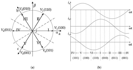
Figure 1.
Illustration of the DTC switching principle: (a) Circular voltage sectors with labeled vectors. (b) Sinusoidal phase currents over one electrical cycle.
3. Adaptive Flux Control Techniques
Adaptive flux control represents a paradigm shift from traditional fixed-flux motor control strategies by enabling real-time adjustment of the stator flux reference in response to varying operating conditions []. Unlike conventional methods that maintain a constant flux regardless of load or speed changes, adaptive control dynamically adjusts the flux magnitude to minimize power losses while preserving torque performance []. This methodology leverages the fundamental observation that optimal flux levels are not fixed, but rather depend on the motor’s instantaneous operating point, allowing for improved efficiency across a broad range of speed–torque combinations [].
The theoretical foundation of this approach lies in the relationship between electromagnetic losses and flux magnitude: copper losses scale with the square of current, while core losses are influenced by flux density. By intelligently adapting the stator flux, both types of losses can be minimized simultaneously. This is particularly advantageous in applications with frequent variations in speed and load, such as electric vehicles and renewable energy systems, where efficiency directly impacts performance and operational costs [].
In the following subsections, two adaptive flux control strategies are presented. The first is the incremental conductance (IncCond) method, which relies on power–flux characteristics to determine optimal flux levels. The second is a Fuzzy Logic-based controller, which adapts the flux reference using a rule-based inference system driven by real-time motor speed and load torque.
3.1. Adaptive Flux Control Using Incremental Conductance
The IncCond method is primarily utilized for MPPT in PV systems [], rather than for direct flux control in motors. In traditional applications, flux control in motors, especially PMSMs, is often achieved through methods like flux-weakening control. For instance, a study by [] presents a voltage-based flux-weakening strategy using a variable incremental controller to manage the flux component current in PMSMs. In this work, it is employed for adaptive flux control of the BLDC motor, aiming to optimize the electromagnetic performance while maintaining stability under varying operating conditions. The IncCond method leverages the instantaneous relationship between power and flux to achieve faster convergence and reduced oscillations.
The proposed Algorithm 1 dynamically adjusts the flux reference based on the incremental change in flux () and power (). The slope is computed, and its sign is used to adjust the flux:
This iterative process ensures that the flux converges to the point where , which corresponds to the maximum power point.
To maintain system stability and prevent excessive adjustments, the flux reference is limited within a predefined range:
where and are the lower and upper bounds of flux, typically set as a percentage of nominal flux.
| Algorithm 1. Incremental Conductance Adaptation Algorithm Steps |
Input:
|
3.2. System Integration and Control Architecture
Figure 2 illustrates the complete control architecture for the proposed BLDC motor drive system, integrating adaptive flux regulation with multi-level control strategies to ensure dynamic performance, torque accuracy, and energy-efficient operation.
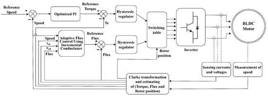
Figure 2.
Control scheme integrating adaptive flux regulation with BLDC motor drive system.
The control loop operates as follows:
- Measurement and Feedback Acquisition: The system continuously measures the stator current components and rotor speed, either via sensors or through sensorless estimation based on back-EMF. These signals form the foundation of the real-time feedback loop.
- Clarke Transformation and Estimation Block: Acquired phase currents are transformed into the stationary reference frame. This enables the estimation of electromagnetic torque, stator flux magnitude, and rotor position—essential parameters for both control and observation tasks.
- Adaptive Flux Regulation via Incremental Conductance: Leveraging the incremental conductance (IncCond) principle, the adaptive control module dynamically adjusts the reference flux. By analyzing the power contribution in the frame (), the controller tunes the flux reference with adaptive step sizes to maintain optimal operating conditions across varying load and speed profiles.
- Speed and Torque Control using Optimized PI Loops: A cascade control structure is adopted, where an outer-loop PI controller regulates speed, and the inner-loop handles current (torque) control. The PI parameters are optimized to maintain closed-loop stability while incorporating the flux reference updates from the adaptive process.
- Hysteresis Current Regulation: Two independent hysteresis regulators compare the measured and reference current components (, ) and generate switching signals when deviations exceed a predefined threshold. This ensures fast current response and reduced torque ripple.
- Switching Table Logic: Based on the outputs from the hysteresis controllers, the switching table determines the appropriate gating signals for the inverter. The commutation strategy adheres to the six-step method, ensuring proper sector alignment with minimal switching losses.
- Inverter and Motor Actuation: The inverter translates control signals into high-speed switching patterns, delivering the regulated voltage and current to the BLDC motor. This final actuation ensures precise torque production and effective utilization of the adaptive flux strategy.
This layered control structure effectively integrates adaptive flux regulation with conventional motor control techniques to enhance overall drive performance. One of its key advantages is the real-time optimization of stator flux using the IncCond method, which operates without the need for a detailed motor model. The control scheme also improves dynamic response through fast hysteresis-based current regulation, while robust speed and torque tracking are achieved via cascade-structured PI controllers. Additionally, the implementation of reliable switching logic ensures efficient commutation across all operating conditions.
Figure 3 illustrates the complete control architecture integrating adaptive fuzzy logic-based flux regulation into the DTC scheme for the BLDC motor drive.
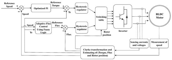
Figure 3.
Control architecture integrating adaptive fuzzy flux control into DTC.
The control system follows a cascaded and real-time feedback loop as described below:
- Clarke Transformation and Estimation Block: The stator currents and voltages are processed through the Clarke transformation to compute the rotor position, electromagnetic torque, stator flux magnitude, and motor speed.
- Adaptive Flux Regulation via Fuzzy Logic: Based on real-time speed and torque feedback, the fuzzy logic controller adaptively updates the reference flux using a predefined rule base and membership functions.
- Speed and Torque Control Using Optimized PI Loop: A speed controller generates the torque reference, which is compared to the actual torque via a hysteresis regulator.
- Hysteresis Regulation: Flux and torque regulators track their respective references and trigger control actions when deviations exceed the hysteresis bounds.
- Switching Table Logic and Inverter Operation: The outputs from the hysteresis regulators and rotor position are used by the switching table to select the appropriate voltage vector for inverter control.
3.3. Adaptive Flux Control Using Fuzzy Logic
In this work, the fuzzy logic module adjusts the stator flux reference in real time based on two key inputs: the motor speed and load torque. The rule base, as shown in Table 2, is constructed to ensure high flux at low speeds (for torque generation), medium flux at moderate conditions (for efficiency), and low flux at high speeds with low torque (to minimize core losses). Similar strategies have been reported in the literature to improve DTC performance and extend battery life in electric vehicles [].

Table 2.
Fuzzy logic rule table for adaptive flux control.
The Algorithm 2 enables real-time flux adaptation, improving energy efficiency under varying load–speed profiles. To achieve this, the controller takes the motor speed and load torque as inputs and produces a scaling factor that adjusts the reference flux accordingly. To maintain the flux within a suitable range, between 70% and 130% of the nominal value, a gain of 1.45 is applied to the output of the fuzzy logic controller. This design assumes that the magnetic circuit remains unsaturated, in line with the modeling assumptions introduced in Section 2. Under this assumption, the flux limits and were empirically determined through a combination of simulation and experimental tuning. These bounds were selected to balance energy efficiency with safe magnetic operation, avoiding both saturation and torque instability.
The fuzzy rule base, presented in Table 2, was initially developed using standard control heuristics rooted in common motor behavior. These rules were then refined through iterative simulation and testing to improve performance under dynamic conditions. Although tailored to the test motor, the fuzzy logic controller maintains a flexible structure, allowing easy adaptation to other BLDC motors by retuning the flux boundaries and adjusting membership functions. This makes the method suitable for a wide range of practical applications. To support real-time implementation, the membership functions used for the fuzzification of the input variables (torque and speed) and the output variable (flux) are kept simple and computationally efficient. As illustrated in Figure 4, each variable is divided into three fuzzy subsets (low, medium, and high) using trapezoidal membership functions. The Mamdani inference system is employed to derive the output, ensuring smooth and interpretable control decisions.
| Algorithm 2. Fuzzy Flux Adaptation Algorithm Steps |
|
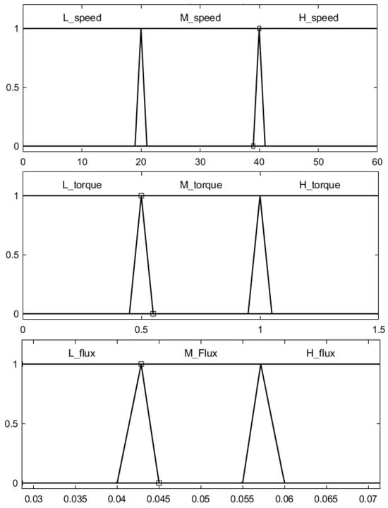
Figure 4.
Fuzzy membership functions using trapezoidal sets and a Mamdani inference system. The first image shows the input speed membership functions, the second shows the input torque membership functions, and the third represents the output flux membership functions.
This hybrid strategy preserves the inherent advantages of classical DTC, such as its fast dynamic response and simple structure, while integrating adaptive flux regulation to improve energy efficiency. Unlike conventional DTC, which relies on fixed flux references and suffers from increased losses under variable load–speed profiles, the proposed approach dynamically adjusts the flux level in real time. Similar improvements through adaptive flux control have been reported in recent works such as [,], reinforcing the practical effectiveness of this control framework.
4. Power Losses
This section outlines the methodology used to compute various forms of power losses in the BLDC motor system. Accurate power calculations are essential for evaluating system efficiency and identifying loss contributors, enabling strategies for performance optimization.
4.1. Core Losses
Core losses in magnetic materials mainly consist of hysteresis and eddy current losses. The total core loss is computed using the following empirical relation:
where denotes the magnetic flux density (Wb/m2), is the hysteresis loss coefficient, which is material-dependent, represents the eddy current loss coefficient, and N is the rotational speed of the rotor expressed in revolutions per minute (rpm).
Hysteresis losses scale linearly with speed, while eddy current losses grow quadratically with speed. This implies that as N increases, eddy current losses dominate the total core loss contribution [].
4.2. Copper Losses
Copper losses are the resistive (Joule) losses due to current flow in the motor windings. In a three-phase BLDC motor, these losses are expressed as:
where, R is the resistance of a single phase winding and I is the RMS value of the current in each phase.
Minimizing copper losses is crucial for enhancing motor efficiency. This can be achieved by using low-resistance materials such as high-conductivity copper, increasing the conductor cross-sectional area to reduce resistance, and optimizing current levels according to the load conditions.
4.3. Total Power Losses
The total losses in the motor system are the sum of the copper and core losses:
This total power loss directly influences system efficiency, calculated as:
By incorporating adaptive flux control strategies (as discussed earlier), both and can be minimized, leading to improved overall drive efficiency.
5. Experimental Results
To assess the practical feasibility of the proposed controller, real-time experiments were conducted using a Hardware-in-the-Loop (HIL) environment incorporating two dSPACE 1104 cards. Using the HIL test bench setup illustrated in Figure 5, combined with the DTC scheme and the switching strategy detailed in Equation (6), this section presents a comparative analysis between the traditional fixed flux reference (set to nominal value) and the two proposed adaptive flux strategies.
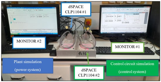
Figure 5.
HIL setup.
5.1. Description of the Experimental Test Bench
In this study, an HIL test bench is developed for the validation of a BLDC motor drive, utilizing two dSPACE cards configured in a master–slave architecture. The master card generates PWM signals for motor control and processes feedback signals, while the slave card simulates the BLDC motor dynamics in real time, providing the necessary responses to close the loop. Communication between the two cards is established via high-speed CAN and synchronized through a dedicated trigger signal. Compared to real-time simulation, HIL testing provides a more accurate validation environment by integrating actual hardware, avoiding the limitations of sensor modeling and signal noise that often affect real-time simulations. In purely simulated environments, sensor imperfections such as noise, offsets, and response delays may not be accurately reproduced, leading to discrepancies between simulation and real-world performance. In the proposed setup, MONITOR 1 runs the control loop and receives key feedback signals from the simulated plant through analog channels. Specifically, ADC1 reads the rotor position, ADC2 captures the torque, ADC3 receives the flux value, and ADC5 monitors the rotor speed, while the PWM control signals generated by the controller are transmitted via the slave I/O interface to drive the inverter gates connected to the plant side. Meanwhile, MONITOR 2 emulates the plant (power system) dynamics; it receives the inverter gate signals via its I/O interface and generates the corresponding analog outputs. These outputs are then transmitted back to the controller side through DAC channels: DAC3 carries the rotor position signal, DAC4 transmits the torque, DAC6 represents the flux, and DAC8 contains the rotor speed. This closed-loop signal exchange replicates the real-time behavior of the BLDC motor system with high fidelity. By using HIL, the control algorithms are tested under realistic conditions, ensuring a more reliable transition to physical implementation.
5.2. Results and Discussion
The experimental validation was designed to comprehensively assess the performance of the BLDC motor drive under all relevant operating conditions. The 24 s test interval was divided into four consecutive 6 s phases, each corresponding to a specific speed level. During the first interval s, the load torque was set to zero while the speed varied through low, medium, and high levels in order to isolate and examine the impact of speed changes alone. In the subsequent intervals, the speed was fixed while the load torque was varied every 2 s to cover low (0.4 N·m), medium (0.8 N·m), and high (1.2 N·m) torque levels. Specifically, in the second interval s, the speed was maintained at a low level; in the third interval s, the speed was medium; and in the final interval s, the speed was high. The PI controller used in the speed regulation loop was carefully tuned through offline optimization to ensure a fast dynamic response and minimal steady-state error, and then integrated into the overall system architecture, as shown in Figure 2 and Figure 3. It is important to note that the transitions in speed and torque were not applied simultaneously; to ensure system stability and avoid overlapping transients, each speed adjustment was introduced approximately 0.1 s before the corresponding torque change. This configuration ensured a stable response and enabled accurate evaluation of each operating point. The updated test scenario matrix is summarized in Table 3, and the applied load torque profile is illustrated in Figure 6.

Table 3.
Speed and torque load combinations for experimental validation.
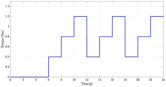
Figure 6.
Load torque profile.
The waveforms for the stator current and back-EMF are shown in Figure 7 and Figure 8, respectively. These figures provide insights into the motor’s behavior, where the stator current follows a sinusoidal pattern for the fixed flux control strategy and the back-EMF exhibits the typical trapezoidal waveform. The experimental results demonstrate the effectiveness of adaptive flux strategies in minimizing power losses and improving system efficiency. The performance of the fixed flux, IncCond, and fuzzy logic control strategies is compared in this section.
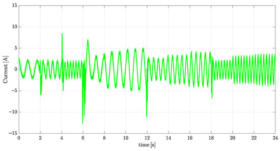
Figure 7.
Stator current waveform under fixed flux control.
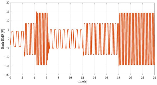
Figure 8.
Back-EMF waveform under fixed flux control.
Figure 9 illustrates the motor speed response under different flux control strategies. The speed profiles appear closely aligned, indicating minimal differences in steady-state performance. However, IncCond exhibits a slightly faster time response compared to fixed flux, particularly during speed transitions. Fuzzy logic outperforms both, achieving the most consistent speed tracking.
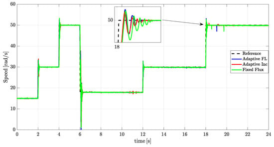
Figure 9.
Speed performance comparison for fixed flux, incremental conductance, and fuzzy logic flux control strategies.
Figure 10 presents the electromagnetic torque profiles under different flux control strategies. The fixed flux case, Figure 10a, delivers the smoothest and most stable torque response, characterized by minimal torque ripple under varying operating conditions, demonstrating superior torque stability compared to both the IncCond and fuzzy logic strategies. The IncCond strategy, Figure 10b, exhibits a reduction in torque oscillations compared to the fuzzy logic approach, and provides a more stable torque response during load transitions, benefiting from its gradient-based flux tuning. Meanwhile, the fuzzy logic approach, Figure 10c, shows significant torque oscillations, particularly during load transitions, due to its dynamic adaptation method. However, this increase in oscillation is an intentional trade-off made to prioritize power loss reduction. The fuzzy controller operates within empirically defined limits for flux ( and ), rotor speed, and load torque, ensuring safe operation while maximizing efficiency. These constraints were established through iterative testing and logical system analysis, allowing the controller to respond adaptively to varying operating conditions while respecting stability margins.
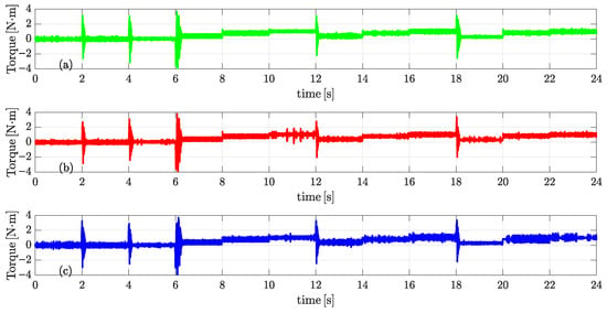
Figure 10.
Electromagnetic torque comparison: (a) fixed flux, (b) incremental conductance, and (c) fuzzy logic.
Figure 11 illustrates the flux profiles under different control strategies. In the fixed flux case, Figure 11a, the flux remains constant regardless of load or speed variations, resulting in suboptimal efficiency due to the lack of adaptability. The IncCond method, Figure 11b, introduces dynamic flux adjustment in response to changing operating conditions, though its responsiveness is limited compared to fuzzy logic. The fuzzy logic strategy, Figure 11c, offers the most effective flux adaptation, dynamically tuning the flux reference based on real-time speed and torque.
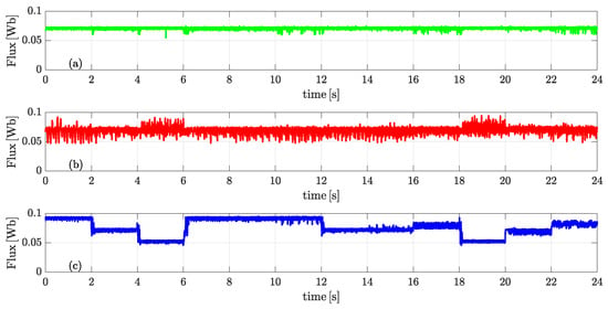
Figure 11.
Flux behavior comparison: (a) fixed flux, (b) incremental conductance, and (c) fuzzy logic.
Figure 12, Figure 13, Figure 14 and Figure 15 present a comparative analysis of the input power, electromagnetic power, core losses, and copper losses, respectively, under the three flux control strategies. While all approaches maintain similar trends, the adaptive strategies IncCond and fuzzy logic demonstrate clear advantages over the fixed flux method. In particular, Figure 12 shows that adaptive flux control effectively reduces the required input power, with the fuzzy logic strategy exhibiting the most pronounced reduction. Figure 13 indicates that the electromagnetic power remains relatively stable across methods, with a slight advantage observed under fuzzy logic control. Regarding core losses in Figure 14, both adaptive strategies introduce small variations, but no significant improvement is evident compared to the fixed approach. However, Figure 15 highlights a marked reduction in copper losses under fuzzy logic control, attributed to its improved current regulation. These observations suggest that while both adaptive methods enhance system performance, the fuzzy logic strategy achieves the most effective balance between input power reduction and loss minimization, particularly in terms of copper losses, thereby contributing to higher overall efficiency.
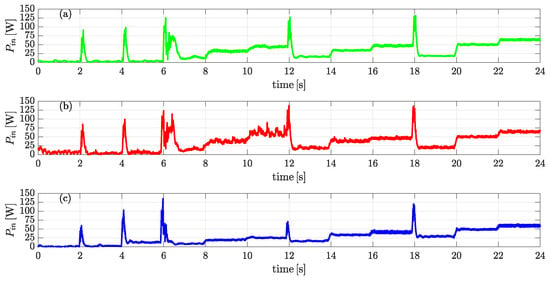
Figure 12.
Input power comparison: (a) fixed flux, (b) incremental conductance, and (c) fuzzy logic.
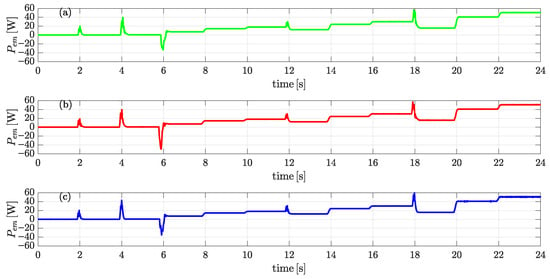
Figure 13.
Electromagnetic power comparison: (a) fixed flux, (b) incremental conductance, and (c) fuzzy logic.
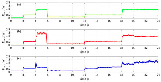
Figure 14.
Core losses comparison: (a) fixed flux, (b) incremental conductance, and (c) fuzzy logic.
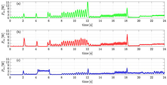
Figure 15.
Copper losses comparison: (a) fixed flux, (b) incremental conductance, and (c) fuzzy logic.
The numerical results of the average power values for each method are summarized in Table 4. These values were computed as mean values over 24 s, which is the standard approach in power system efficiency analysis. This average-based evaluation reflects the long-term electrical stress on the motor [].

Table 4.
Mean power calculations and efficiency comparison.
Among the three strategies, fuzzy logic exhibits the best overall performance. It achieves the lowest input power consumption at while delivering the highest electromagnetic power at . In addition, it significantly reduces copper losses to and core losses to , both of which are the lowest among all methods. This results in the lowest total power losses, amounting to , and leads to a system efficiency of —the highest observed. The IncCond method offers intermediate performance, with an input power of , electromagnetic power of , core losses of , and copper losses of . Its total power losses are reduced to , corresponding to a loss reduction compared to the fixed flux approach. The system efficiency achieved is . In contrast, the fixed flux strategy results in the highest energy losses and the lowest system efficiency, with an input power of , total power losses of , and an overall efficiency of . These results validate the effectiveness of adaptive flux control—particularly fuzzy logic—in minimizing power losses and enhancing overall drive efficiency. The bar charts in Figure 16 present a visual summary of the performance metrics listed in Table 4, highlighting efficiency, input power, total losses, and copper losses for the fixed flux, incremental conductance, and fuzzy logic strategies.
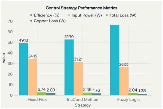
Figure 16.
Control strategy performance metrics: efficiency, input power, and total and copper losses for fixed flux, incremental conductance, and fuzzy logic approaches.
The experimental results clearly validate the effectiveness of adaptive flux control strategies in minimizing power losses and enhancing the overall efficiency of BLDC motor drives. Among the three evaluated methods, the fuzzy logic controller achieved the best overall performance, realizing a 25.55% reduction in total power losses and a system efficiency of 66.59%. The incremental conductance approach also demonstrated significant benefits, yielding a 10.22% loss reduction compared to the fixed flux baseline. These improvements were achieved through intelligent real-time flux regulation: the IncCond method provided fast and responsive flux adaptation based on power–flux gradient analysis, while the fuzzy controller fine-tuned the flux reference using a rule-based system informed by motor speed and load torque.
All strategies were implemented and validated using an HIL environment based on a dual dSPACE 1104 card setup. The control algorithm was executed in real time using a DTC scheme, where accurate flux estimation was enabled by leveraging the known internal parameters of the BLDC motor. The real-time simulation model of the motor included detailed modeling of electromagnetic dynamics, core losses, and switching behavior, ensuring high-fidelity interaction between hardware and simulation domains. The use of a small-scale 100 W BLDC motor, with fully characterized internal parameters, allowed precise analysis of efficiency trends and loss mechanisms across a wide range of operating points.
The proposed framework, integrating IncCond and fuzzy logic within a real-time DTC control architecture, demonstrates a practical, scalable, and energy-efficient solution for intelligent motor drives. It successfully bridges advanced control theory and embedded implementation, offering a concrete pathway toward optimized flux control in energy-sensitive applications. The demonstrated loss minimization, control responsiveness, and implementation feasibility collectively represent a meaningful contribution to the advancement of BLDC motor drives.
5.3. Comparative Analysis with Related Works
To highlight the effectiveness of the proposed adaptive flux control strategies, Table 5 provides a comparison with relevant studies focused on minimizing power losses in BLDC motor drives using various advanced control techniques. The table summarizes the control strategy, validation method, reported loss reduction, and key implementation notes.

Table 5.
Comparison of different control strategies for power loss minimization in BLDC motor drives.
As summarized in Table 5, the proposed fuzzy logic-based adaptive flux controller achieves the highest loss reduction of 25.55%, outperforming other advanced strategies such as MTPA with pseudo-FOC (23.1%), harmonic-based switching (20.3%), and adaptive PI control (18.6%). While these methods improve efficiency through techniques like optimized torque utilization, harmonic suppression, or adaptive gain tuning, they do not directly implement real-time adaptive flux control. In contrast, the fuzzy logic and incremental conductance strategies presented in this work are the only approaches in the comparison that explicitly regulate the flux reference for BLDC motor drives based on instantaneous speed and torque conditions. This distinction underscores the practical relevance and effectiveness of adaptive flux control in reducing copper and core losses under dynamic operating conditions, as demonstrated through HIL-based validation.
6. Conclusions
This work presented a novel adaptive flux control strategy for BLDC motors that intelligently adjusts the stator flux in real-time to reduce power losses and improve overall system efficiency. The proposed framework integrates IncCond and FLCs to adaptively regulate flux based on varying speed and load conditions. Experimental validation on a 100 W BLDC motor confirmed that the adaptive strategy significantly outperforms conventional fixed flux control in terms of energy efficiency and power loss reduction. The IncCond method achieved a 10.22% reduction in total power losses compared to fixed flux control by leveraging the instantaneous power–flux relationship for fast and responsive flux adaptation. Originally developed for photovoltaic systems, IncCond proved highly effective in BLDC motor control, enhancing system dynamics under changing load and speed conditions.
Subsequently, the fuzzy logic controller further improved performance by incorporating expert knowledge to adjust the stator flux based on real-time speed and torque inputs. This strategy delivered the best overall results, achieving a 25.55% loss reduction relative to the fixed flux approach, especially under dynamic operating scenarios. Although the implementation was carried out on a small-scale motor, the proposed methodology is scalable to larger motors and drive systems. The observed trends in loss reduction and control performance are expected to translate effectively to applications such as electric vehicles and renewable energy systems, where efficiency optimization is critical.
In summary, the proposed adaptive control approach offers a robust and scalable solution for minimizing losses in BLDC motor drives. Future research will focus on integrating this strategy into multi-level control architectures and further refining the fuzzy rule base and adaptation logic for enhanced real-time performance in embedded applications.
Author Contributions
Conceptualization, M.F.K. and O.C.; methodology, M.F.K. and A.B.; software, M.F.K.; validation, M.S. and C.B.; formal analysis, M.S.; investigation, M.F.K. and M.S.; writing—original draft preparation, M.F.K.; writing—review and editing, M.S.; supervision, O.C.; project administration, C.B. All authors have read and agreed to the published version of the manuscript.
Funding
This research received no external funding.
Conflicts of Interest
The authors declare no conflicts of interest.
References
- Shenbagalakshmi, R.; Mittal, S.K.; Subramaniyan, J.; Vengatesan, V.; Manikandan, D.; Ramaswamy, K. Adaptive speed control of BLDC motors for enhanced electric vehicle performance using fuzzy logic. Sci. Rep. 2025, 15, 12579. [Google Scholar] [CrossRef]
- Pedapenki, K.; Kumar, J.; Anumeha. Fuzzy Logic Controller-Based BLDC Motor Drive. In Proceedings of the 2022 IEEE International Power and Renewable Energy Conference (IPRECON), Kollam, India, 16–18 December 2022; IEEE: Piscataway, NJ, USA, 2022. [Google Scholar]
- Rahim, A.; Singh, R. BLDC motor speed control with digital adaptive PID–Fuzzy. Energies 2023, 17, 1311. [Google Scholar]
- Sevugan Rajesh, J.; Karthikeyan, R.; Revathi, R. Analysis and control of grid-interactive PV-fed BLDC water pumping system with optimized MPPT for DC-DC converter. Sci. Rep. 2024, 14, 25963. [Google Scholar] [CrossRef]
- Muthamizhan, T.; Silas Stephen, D.; Sivakumar, A. ANFIS Controller Based Speed Control of High-Speed BLDC Motor Drive; IOS Press: Amsterdam, The Netherlands, 2020. [Google Scholar]
- Almasi, O.; Fereshtehpoor, V.; Khooban, M.; Blaabjerg, F. Non-inverting buck-boost converter using T–S fuzzy PI control. IEEE Trans. Power Electron. 2017, 32, 9143–9178. [Google Scholar]
- Arya, P.; Althaf, P.; Haridas, A.; Mohanan, J. Brushless DC motor speed control using fuzzy-PID. AIP Conf. Proc. 2024, 3134, 110008. [Google Scholar] [CrossRef]
- Iqbal, A. Chaos control of brushless direct current motor using sliding mode control with a low cost hardware-in-loop validation. Sci. Talks 2025, 14, 100453. [Google Scholar] [CrossRef]
- Udayakumar, A.K.; Raghavan, R.R.V.; Houran, M.A.; Elavarasan, R.M.; Kalavathy, A.N.; Hossain, E. Three-port bi-directional DC–DC converter with solar PV system fed BLDC motor drive using FPGA. Energies 2023, 16, 624. [Google Scholar] [CrossRef]
- Akrami, M.; Jamshidpour, E.; Nahid-Mobarakeh, B.; Pierfederici, S.; Frick, V. Sensorless control methods for BLDC motor drives: A review. IEEE Trans. Transp. Electrif. 2024, 11, 135–152. [Google Scholar] [CrossRef]
- Zhang, H.; Deng, L.; Li, H.; Zheng, S.; Jin, H.; Chen, B. Commutation point optimization method for sensorless BLDC motor control using vector phase difference of back EMF and current. IEEE/Asme Trans. Mechatron. 2023, 29, 423–433. [Google Scholar] [CrossRef]
- Santra, S.B.; Chatterjee, A.; Chatterjee, D.; Padmanaban, S.; Bhattacharya, K. High efficiency operation of brushless DC motor drive using optimized harmonic minimization based switching technique. IEEE Trans. Ind. Appl. 2022, 58, 2122–2133. [Google Scholar] [CrossRef]
- Bhosale, R.; Warshe, W.; Shreelakshmi, M.; Arlikar, P.; Prakash, A.; Agarwal, V. Performance comparison of Two PWM techniques applied to BLDC motor control. In Proceedings of the 2018 International Conference on Power, Instrumentation, Control and Computing (PICC), Thrissur, India, 18–20 January 2018; IEEE: Piscataway, NJ, USA, 2018; pp. 1–6. [Google Scholar]
- Czerwinski, D.; Gęca, J.; Kolano, K. Machine learning for sensorless temperature estimation of a BLDC motor. Sensors 2021, 21, 4655. [Google Scholar] [CrossRef] [PubMed]
- Antony, R.P.; Komarasamy, P.R.G.; Rajamanickam, N.; Alroobaea, R.; Aboelmagd, Y. Optimal rotor design and analysis of energy-efficient brushless dc motor-driven centrifugal monoset pump for agriculture applications. Energies 2024, 17, 2280. [Google Scholar] [CrossRef]
- Sayed, K.; El-Zohri, H.H.; Ahmed, A.; Khamies, M. Application of tilt integral derivative for efficient speed control and operation of BLDC motor drive for electric vehicles. Fractal Fract. 2024, 8, 61. [Google Scholar] [CrossRef]
- Xu, Q.; Fang, S. Robust deadbeat predictive current sensorless control for permanent magnet synchronous motor. IEEE Trans. Power Electron. 2024, 39, 11441–11454. [Google Scholar] [CrossRef]
- Bian, F.; Chien, Y.R. PMSM Speed Control Based on Improved Adaptive Fractional-Order Sliding Mode Control. Symmetry 2025, 17, 736. [Google Scholar] [CrossRef]
- Sun, Q.; He, S.; Liu, X.; Niu, F.; Gan, C.; Jia, G. Four-Point Trajectory Tracking Control of PMSMs with Improved Dynamic Response and Steady-State Efficiency. IEEE Trans. Ind. Electron. 2024, 72, 3482–3491. [Google Scholar] [CrossRef]
- Uddin, M.N.; Zou, H.; Azevedo, F. Online loss-minimization-based adaptive flux observer for direct torque and flux control of PMSM drive. IEEE Trans. Ind. Appl. 2015, 52, 425–431. [Google Scholar] [CrossRef]
- Naqvi, S.S.A.; Jamil, H.; Iqbal, N.; Khan, S.; Lee, D.I.; Park, Y.C.; Kim, D.H. Multi-objective optimization of PI controller for BLDC motor speed control and energy saving in Electric Vehicles: A constrained swarm-based approach. Energy Rep. 2024, 12, 402–417. [Google Scholar] [CrossRef]
- Leninpugalhanthi, P.; Latha, R. Adaptive PID controller based direct torque control of fuel cell fed BLDC drive for industrial drives applications. Therm. Sci. Eng. Prog. 2024, 55, 102931. [Google Scholar] [CrossRef]
- Rambabu, S. Modeling and Control of a Brushless DC Motor. Master’s Thesis, National Institute of Technology Rourkela, Rourkela, India, 2007. [Google Scholar]
- Romeral, L.; Fabrega, A.; Cusido, J.; Garcia, A.; Ortega, J. Torque ripple reduction in a PMSM driven by direct torque control. In Proceedings of the 2008 IEEE Power Electronics Specialists Conference, Rhodes, Greece, 15–19 June 2008. [Google Scholar]
- Lad, C.K.; Chudamani, R. Simple overlap angle control strategy for commutation torque ripple minimisation in BLDC motor drive. IET Electr. Power Appl. 2018, 12, 797–807. [Google Scholar] [CrossRef]
- More, P.; Panchade, V. Control Strategies for BLDC Motor. Int. J. Adv. Res. Electr. Electron. Instrum. Eng. 2016, 5, 5578–5583. [Google Scholar]
- Ahmad, A.; Khan, F.; Jamil, M. Detection of Rotor Faults in BLDC Motor Using Flux Analysis. Results Eng. 2024, 20, 1464–1477. [Google Scholar]
- Abbas, A.; Latif, M.; Zhang, H. A Review of Adaptive Energy Control in Sustainable Transportation. Sustainability 2024, 17, 5841. [Google Scholar]
- Necaibia, S.; Kelaiaia, M.S.; Labar, H.; Necaibia, A.; Castronuovo, E.D. Enhanced auto-scaling incremental conductance MPPT method, implemented on low-cost microcontroller and SEPIC converter. Sol. Energy 2019, 180, 152–168. [Google Scholar] [CrossRef]
- Lee, H.; Lee, G.; Kim, G.; Shon, J. Variable incremental controller of permanent-magnet synchronous motor for voltage-based flux-weakening control. Energies 2022, 15, 5733. [Google Scholar] [CrossRef]
- Khazaee, A.; Zarchi, H.A.; Markadeh, G.A. Loss Model Based Efficiency Optimized Control of Brushless DC Motor Drive. ISA Trans. 2019, 92, 207–218. [Google Scholar] [CrossRef]
- Zhang, Q.; Deng, J.; Fu, N. Minimum Copper Loss Direct Torque Control of Brushless DC Motor Drive in Electric and Hybrid Electric Vehicles. IEEE Access 2019, 7, 144866–144875. [Google Scholar] [CrossRef]
- Bose, B.K. Power Electronics and AC Drives; Prentice Hall: Englewood Cliffs, UK, 1986. [Google Scholar]
- Bose, B.K. Modern Power Electronics and AC Drives; Prentice Hall: Saddle River, NJ, USA, 2002. [Google Scholar]
- Nag, T.; Santra, S.B.; Chatterjee, A.; Chatterjee, D.; Ganguli, A.K. Fuzzy logic-based loss minimisation scheme for brushless DC motor drive system. IET Power Electron. 2016, 9, 1581–1589. [Google Scholar] [CrossRef]
- Praptodiyono, S.; Maghfiroh, H.; Hermanu, C. BLDC Motor Control Optimization Using Optimal Adaptive PI Algorithm. J. Elektron. Dan Telekomun. 2020, 20, 47–52. [Google Scholar] [CrossRef]
- Singh, R.R.; Kalel, D.D.; Stonier, A.A.; Peter, G.; Stephen, V.; Arun, V.; Ganji, V. MTPA With Pseudo-FOC Strategy–Based BLDC for Minimization of Copper Loss and Torque Ripple. J. Electr. Comput. Eng. 2025, 2025, 2549885. [Google Scholar] [CrossRef]
Disclaimer/Publisher’s Note: The statements, opinions and data contained in all publications are solely those of the individual author(s) and contributor(s) and not of MDPI and/or the editor(s). MDPI and/or the editor(s) disclaim responsibility for any injury to people or property resulting from any ideas, methods, instructions or products referred to in the content. |
© 2025 by the authors. Licensee MDPI, Basel, Switzerland. This article is an open access article distributed under the terms and conditions of the Creative Commons Attribution (CC BY) license (https://creativecommons.org/licenses/by/4.0/).