Abstract
In this paper, an adaptive dynamic event-triggered sliding mode control scheme is proposed for a pneumatic vibration isolation platform. First, an experimental platform is designed and constructed, and a corresponding dynamic model is established, which explicitly accounts for the unknown threshold voltage at the input side. Based on this model, an adaptive sliding mode controller is developed. Then, to suppress unnecessary actuator updates, a dynamic event-triggered mechanism is introduced. Lyapunov-based analysis demonstrates the stability of the closed-loop system and guarantees the exclusion of Zeno behavior. Finally, experimental results on the pneumatic platform verify the effectiveness and superiority of the proposed approach.
1. Introduction
Active pneumatic vibration isolation platforms can effectively isolate and attenuate vibration disturbances while supporting heavy payloads with relatively low energy consumption, and have therefore been widely applied in semiconductor manufacturing, precision measurement, ultra-precision machining, and agricultural production [1,2,3,4]. As the core component of such platforms, pneumatic actuators regulate the chamber pressure through control valves, converting compressed air into mechanical motion to ensure fast response capability. In practical applications, pneumatic isolation platforms are not only employed for vibration suppression but also frequently undertake trajectory tracking and precise positioning tasks. However, pneumatic control systems inherently exhibit significant nonlinear characteristics and are further influenced by parameter uncertainties, dead-zone effects, air leakage, and load variations. These complexities make it difficult for conventional control methods to guarantee robustness and stability in high-precision scenarios. Therefore, the development of robust and efficient control strategies is of great importance for improving actuator performance and enhancing the engineering value of pneumatic vibration isolation platforms.
Nonlinear control has been extensively studied, yielding methods such as predictive control [5], operator-based robust right coprime factorization approach [6], and sliding-mode control [7]. Sliding mode control has been extensively acknowledged for its strong robustness against system uncertainties and external disturbances, and has been successfully employed in a wide range of nonlinear systems, and it can be integrated with other methodologies to enhance performance [8,9,10,11,12,13]. In [14], an adaptive integral sliding mode control scheme is proposed for uncertain systems with unknown disturbances and dead zones, where the dead-zone effect is treated as a compounded disturbance addressed by a sliding mode disturbance observer. Furthermore, to cope with unknown parameters in systems, adaptive control has emerged as an effective method. Typically, adaptive control achieves this by parameter estimation and online updating mechanisms, together with adaptive laws designed using Lyapunov stability theory, so as to adjust control gains in real time, thereby compensating for uncertainties caused by unknown parameters [15,16]. Owing to its capability of online learning and parameter adaptation, adaptive control can effectively enhance control accuracy and reduce the conservatism of sliding mode robust designs, making it particularly suitable for complex nonlinear systems. Although these methods improve robustness and adaptivity, they are still implemented under a conventional time-triggered framework, in which the controller is adjusted at every sampling instant. Such frequent updates not only impose unnecessary computational and communication burdens but also accelerate actuator wear, thereby reducing energy efficiency and shortening service life. Therefore, it remains an important problem to investigate how to reduce the control-update frequency while ensuring robustness and stability.
Fortunately, event-triggered control has emerged, in which the control signal is updated or transmitted only according to a predefined triggering mechanism, thereby ensuring system performance from both stability and efficiency perspectives [17,18]. Recently, various types of event-triggered control mechanisms have been proposed, which can be classified according to their triggering properties, such as fixed-threshold event-triggered control [19], relative-threshold event-triggered control [18,20], switching-threshold event-triggered control [21], and static event-triggered control [22]. Recently, the idea of dynamic event-triggered control has been introduced, in which a positive auxiliary variable is incorporated to dynamically adjust the triggering threshold. Compared with static event-triggered schemes, it not only reduces the number of triggering events and obtains larger inter-event time intervals but also achieves a better trade-off between control performance and resource utilization [23,24,25]. In addition, in [26], a backstepping-based dynamic event-triggered mechanism is designed, which ensures zero tracking/stabilization error while effectively excluding Zeno behavior.
In this paper, an adaptive dynamic event-triggered sliding mode control scheme is proposed for the pneumatic vibration isolation system. The controller design accounts for unknown threshold voltages induced by air leakage, payload mass, and dead zones. Moreover, the scheme can significantly reduce the controller update frequency and achieve effective trajectory tracking. The main contributions are as follows:
- A pneumatic vibration isolation platform is designed and constructed, and the corresponding dynamic model is established, where the model considers the unknown threshold voltage at the input side.
- An adaptive dynamic event-triggered sliding mode tracking control strategy is proposed, wherein a novel dynamic event-triggered mechanism is constructed accompanied by a rigorous Lyapunov-based stability proof, which also guarantees the exclusion of Zeno behavior. Unlike existing methods, the designed controller provides adaptive compensation for the unknown threshold voltage. Moreover, the introduced dynamic event-triggered mechanism effectively suppresses unnecessary actuator switching, thereby improving energy efficiency and extending actuator lifespan.
- Experimental results verify the effectiveness and superiority of the proposed approach, showing a significant reduction in control updates compared with conventional time-triggered methods.
2. Experimental Setup and Dynamic Modeling
2.1. Experimental Setup
The experimental setup is constructed to evaluate the proposed control strategy, as shown in Figure 1. The system consists of an air compressor, an electro-pneumatic regulator, a pneumatic actuator mechanically connected to a single-link arm structure, a displacement sensor, regulated DC power supplies, a National Instruments USB-6000 series data acquisition (DAQ) device, and a computer. The compressed air is regulated before driving the pneumatic actuator, whose output is measured by the displacement sensor. The regulated DC power supplies provide stable voltage sources for powering the displacement sensor. The DAQ device serves as the interface between the computer and the regulator for both control input and signal acquisition. The experimental computer is a Lenovo Xiaoxin laptop running Microsoft Windows, and all control algorithms are implemented in MATLAB. The specifications of the main hardware components are summarized in Table 1.
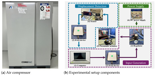
Figure 1.
Experimental setup: (1) Computer; (2) Data acquisition device; (3) Electro-pneumatic regulator; (4) Displacement sensor; (5) Pneumatic actuator with single-link arm load; (6) Regulated DC power supply.

Table 1.
Specifications of the experimental setup components.
2.2. Pneumatic System Modeling
Figure 2 illustrates the overall schematic of the pneumatic vibration isolation system, including the interactions among the air spring, compressor, electro-pneumatic regulator, sensor, and controller, together with the force transmission pathways acting on the payload.
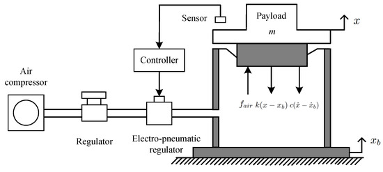
Figure 2.
System schematic of the pneumatic vibration isolation platform and payload force interactions.
According to the force analysis in Figure 2, the dynamic model of the pneumatic vibration isolation system is given by
where x is the displacement, m is the equivalent load mass, c is the damping coefficient, and k is the equivalent spring stiffness. The base is assumed to remain stationary during the experiments, implying . Consequently, the dynamic model (1) can be simplified to the linear form.
The pneumatic actuation force is related to the effective command through an identified gain:
where is the actuator gain identified from experimental data through curve fitting and approximated as constant.
The effective input is subject to a unknown threshold voltage, which can be modeled as
where is the command voltage and is the unknown threshold voltage. Figure 3 illustrates the characteristic of Equation (3).
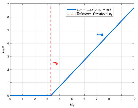
Figure 3.
Unknown threshold voltage characteristic.
To facilitate controller design, the dynamic model (1) can be rewritten as the following linear state-space form. Specifically, let and , and the dynamics can be expressed as
2.3. Tracking-Error System
Based on the state-space representation in (4), we now derive the tracking-error dynamics with respect to a given reference trajectory.
We consider a desired reference trajectory , and it is assumed to be twice-differentiable. Then, the tracking errors can be defined as
Then, the error dynamics can be expressed as
where
Based on the developed experimental pneumatic platform and the derived error system, the control objectives of this work are (1) to compensate for the unknown input bias and external disturbances through an adaptive method; (2) to achieve high-precision trajectory tracking of the reference signal; (3) to reduce the control-update frequency by employing a dynamic event-triggered strategy, thereby improving energy efficiency and extending actuator durability.
3. Design of Controllers
In order to solve the trajectory tracking control problem of the developed experimental pneumatic platform, this section designs two adaptive sliding mode controllers. The first employs a conventional time-triggered mechanism, while the second adopts a dynamic event-triggered mechanism.
3.1. Time-Triggered Adaptive Sliding Mode Controller
To design the controller, we construct the following sliding mode surface by integrating proportional–integral–derivative error terms
where , , and are positive design parameters.
Based on (10), the controller is designed as
where denotes the estimate of the unknown threshold voltage, is the equivalent control component, and ensures robustness against uncertainties.
The equivalent controller is designed as
with
The robust term is designed to guarantee stability in the presence of residual uncertainties:
where and are positive design parameters.
Furthermore, the adaptive law for is chosen as
with denoting the adaptation gain.
Theorem 1.
Proof.
Consider the Lyapunov function candidate
where is the estimation error.
Its time derivative along the closed-loop trajectories is
Since , using the adaptive law (14) yields
To evaluate , substitute the control law (11) together with (12) and (13) into (10), so one has
Substituting (17) and (18) into (16), we obtain
Thus, s can converge to the origin, and according to its definition, the tracking error and can also converge to zero as [27]. The proof is complete. □
In the time-triggered scheme, the actuator must be updated at every sampling instant, and such high-frequency operations accelerate its wear. To address this issue, a dynamic event-triggered mechanism is introduced in the next section.
3.2. Dynamic Event-Triggered Sliding Mode Control
In this framework, the control input is updated only when a triggering condition is violated, rather than at every sampling instant. This strategy substantially reduces communication and actuation efforts while preserving stability and excluding Zeno behavior.
The event-triggered controller is defined as
where denotes the i-th triggering instant, is the sliding mode control law, is the piecewise constant control signal actually applied to the plant, and are design constants, and is the event-triggered parameter. The scalar is a design parameter that adjusts the event-triggered condition. is the sampling error defined as
which represents the difference between the implemented control and the continuous control law. The auxiliary variable in (20) provides additional flexibility in the triggering condition and is generated by the following differential equation:
where is a design parameter and the initial condition satisfies .
Lemma 1.
Proof.
From the triggering condition (20), we have
By the comparison lemma, it follows that
Hence, holds for all , which completes the proof.
□
Then, we give the following Theorem.
Theorem 2.
Consider the closed-loop system composed of the error dynamics (7), the sliding variable (9), and the adaptive sliding mode control law (11)–(14) implemented under the dynamic event-triggered mechanism (20)–(22). Then all closed-loop trajectories are bounded, and the sliding variable converges to zero.
Proof.
Consider the composite Lyapunov candidate
Differentiating (27) along the trajectories of the closed-loop system yields
With applied to the plant, the dynamics of s can be expressed as
From the adaptive update law (14), we obtain
By applying the inequality , we obtain
Then, it follows that
Hence, we can conclude that as , and according to the definition of s in (9), the tracking errors and converge to zero, and that and as . The proof is complete. □
Based on the above theoretical results, the overall control architecture can be illustrated in Figure 4.
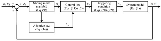
Figure 4.
The proposed dynamic event-triggered control framework.
Remark 1.
In practical implementation, the discontinuous function in (13) is usually replaced by its smooth approximation with in order to alleviate chattering.
3.3. Exclusion of Zeno Behavior
Theorem 3.
Under the proposed event-triggered mechanism, the inter-event times satisfy the lower bound
which guarantees the exclusion of Zeno behavior. Here, and U are positive constants, with their specific definitions provided in subsequent derivations.
Taking the derivative of , one has
According to (11)–(14) and Remark 1, the derivative of is uniformly bounded, and there exists a constant such that
Therefore, under (35), it has
Accordingly, the next triggering instant occurs when the right-hand side of (36) exceeds the following triggering threshold:
Due to guaranteed by Lemma 1, there exists a positive lower bound such that
Therefore, Zeno behavior is rigorously excluded.
4. Experiments
In this section, to validate the effectiveness and superiority of the proposed control scheme, we conduct three comparative experiments: a time-triggered control scheme, a time-triggered control scheme without adaptive parameters, and a dynamic event-triggered control scheme. The system and design parameters are given in Table 2, in which the design parameters are selected via trial and error method, consistent with the theoretically derived design ranges.
Table 2.
Values of plant, controller, and event-triggered parameters.
In this case, the base is fixed, and thus we directly plot the platform displacement. First, the experimental results under the time-triggered control scheme are summarized in Figure 5, Figure 6, Figure 7, Figure 8 and Figure 9. To evaluate the effectiveness and robustness of the proposed method, a load disturbance is applied to the air spring at approximately , and a open-loop constant feedforward method is included for comparison. Figure 5 depicts the tracking trajectory, while Figure 6 presents the tracking error. Although small tracking errors remain, they are mainly attributable to sensor measurement noise and lie within an acceptable range. Furthermore, it can be seen that after the disturbance is applied and dissipates, the system state can quickly return to the desired value. In contrast, under the open-loop constant-input baseline without sliding mode control, the trajectory fails to converge or maintain the target position, thereby further demonstrating the effectiveness of the proposed scheme. Figure 7 depicts the control input. Figure 8 shows the sliding surface, which converges to a small neighborhood around zero. Finally, Figure 9 presents the adaptive estimate parameter , whose estimated value is consistent with the actual condition.
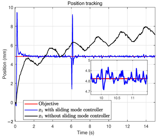
Figure 5.
Tracking trajectory under the time-triggered scheme.
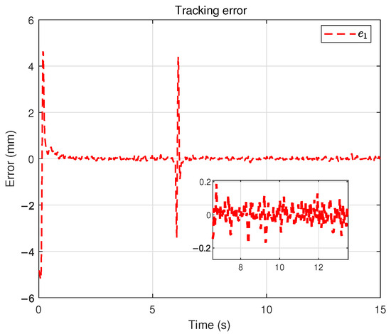
Figure 6.
Tracking error under the time-triggered scheme.
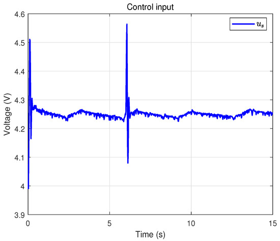
Figure 7.
Control input under the time-triggered scheme.
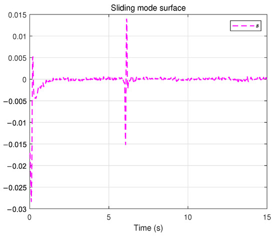
Figure 8.
Sliding surface under the time-triggered scheme.
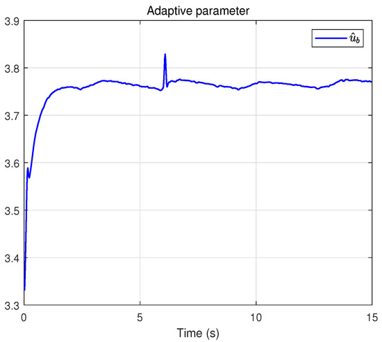
Figure 9.
Adaptive parameter under the time-triggered scheme.
For comparison, the results of a time-triggered controller without adaptive parameters are presented in Figure 10, Figure 11 and Figure 12. Specifically, Figure 10 illustrates the tracking trajectory. Figure 11 depicts the corresponding tracking error. Finally, Figure 12 reports the control input. From the comprehensive comparison of Figure 5, Figure 6 and Figure 7 and Figure 10, Figure 11 and Figure 12, it can be observed that the incorporation of adaptive control effectively improves the convergence speed and robustness, while ensuring satisfactory tracking accuracy.
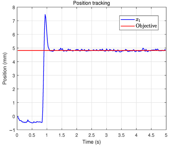
Figure 10.
Tracking trajectory under the time-triggered scheme (non-adaptive).
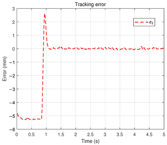
Figure 11.
Tracking error under the time-triggered scheme (non-adaptive).
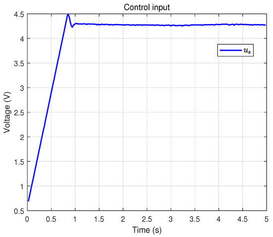
Figure 12.
Control input under the time-triggered scheme (non-adaptive).
Finally, the results obtained with the dynamic event-triggered control scheme are shown in Figure 13, Figure 14, Figure 15, Figure 16, Figure 17, Figure 18 and Figure 19. Figure 13 shows the system trajectory, and Figure 14 shows the tracking error, which is slightly inferior to the time-triggered method in terms of accuracy. However, as observed from the control input result in Figure 15, dynamic event-triggered method significantly reduces the actuator update frequency, which helps prolong the actuator’s service life. Figure 16 confirms that the sliding surface still converges near zero. Figure 17 displays the adaptive estimation of uncertain parameters.Figure 18 presents the event-triggered condition with a dynamically adjustable threshold. Figure 19 shows the auxiliary dynamic variable, which is always positive. Overall, dynamic event-triggered control method achieves a favorable trade-off by significantly reducing the control-update burden at the cost of a small loss in tracking accuracy.
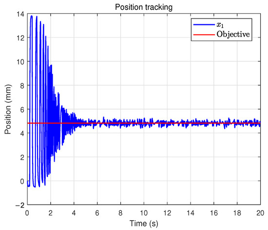
Figure 13.
Tracking trajectory under the dynamic event-triggered control scheme.
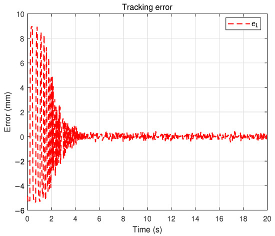
Figure 14.
Tracking error under the dynamic event-triggered control scheme.
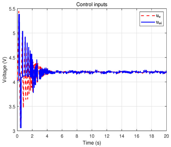
Figure 15.
Event-triggered control input .
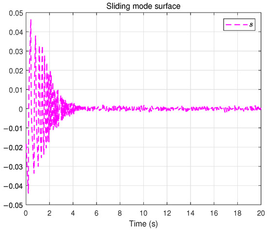
Figure 16.
Sliding surface under the dynamic event-triggered control scheme.
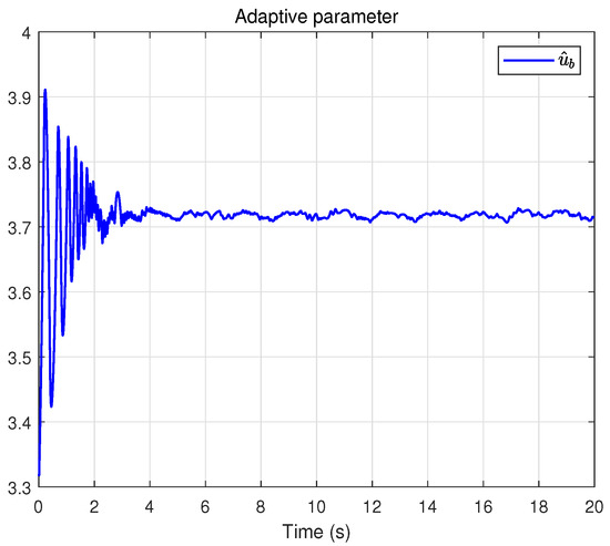
Figure 17.
Adaptive parameter under the dynamic event-triggered control scheme.
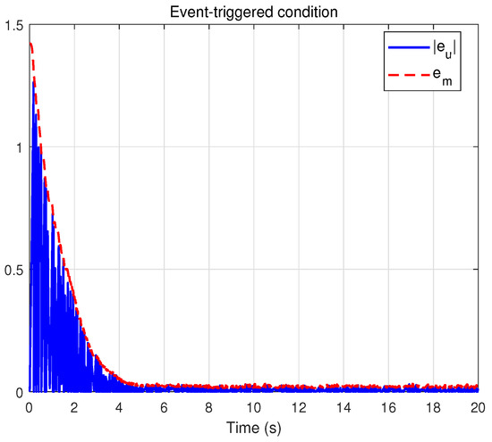
Figure 18.
Evolution of the dynamic event-triggered condition.
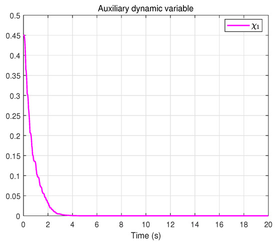
Figure 19.
Auxiliary dynamic variable.
To further demonstrate the effectiveness and superiority of the dynamic event-triggered mechanism, we compare it with the conventional time-triggered scheme and the static event-triggered scheme. When the auxiliary variable is fixed as , the dynamic event-triggered condition reduces to the traditional static form. Figure 20 shows the static event-triggered condition, and the comparison results are summarized in Table 3. Under the time-triggered control, the number of triggers reaches 2000, with an average trigger interval of 0.01 s and a trigger rate of 100%, since the control input is updated at every sampling instant. In contrast, the static event-triggered control reduces the number of triggers to 403, increases the average trigger interval to 0.0496 s, and decreases the trigger rate to 20.15%, indicating that the triggering condition can effectively suppress unnecessary updates. Furthermore, the dynamic event-triggered control exhibits the most significant improvement, with only 321 triggers, an average trigger interval extended to 0.0623 s, and the trigger rate further reduced to 16.05%. These results clearly verify that the dynamic event-triggered mechanism can substantially reduce the actuator update frequency while maintaining system performance, thereby lowering energy consumption and prolonging actuator lifespan.
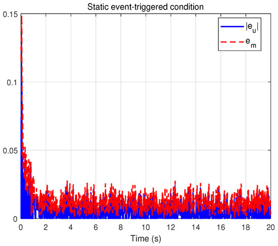
Figure 20.
Evolution of the static event-triggered condition.
Table 3.
Triggering statistics of different control schemes.
5. Conclusions
In this paper, an adaptive dynamic event-triggered sliding mode control scheme was proposed for a pneumatic vibration isolation platform. The stability of the closed-loop system was demonstrated through Lyapunov theory, and the effectiveness of the control scheme was experimentally validated on the platform. The results confirmed that the proposed approach achieves accurate trajectory tracking while significantly reducing actuator update frequency compared with conventional time-triggered control. Future work will focus on exploring other control schemes for the pneumatic vibration isolation system to further enhance performance.
Author Contributions
Conceptualization, M.D.; Methodology, H.Z. and Z.A.; Software, H.Z.; Validation, Z.A.; Investigation, H.Z., Z.A. and G.Z.; Data curation, Z.A.; Writing—review & editing, M.D.; Supervision, M.D. and G.Z. All authors have read and agreed to the published version of the manuscript.
Funding
This research received no external funding.
Institutional Review Board Statement
Not applicable.
Informed Consent Statement
Not applicable.
Data Availability Statement
Data are contained within the article.
Conflicts of Interest
The authors declare no conflicts of interest.
References
- Bergerman, M.; Van Henten, E.; Billingsley, J.; Reid, J.; Deng, M. IEEE robotics and automation society technical committee on agricultural robotics and automation. IEEE Robot. Autom. Mag. 2013, 20, 20–23. [Google Scholar] [CrossRef]
- Kato, T.; Kawashima, K.; Sawamoto, K.; Kagawa, T. Active control of a pneumatic isolation table using model following control and a pressure differentiator. Precis. Eng. 2007, 31, 269–275. [Google Scholar] [CrossRef]
- Shirani, H.; Wakui, S. Control of an isolated table’s fluctuation caused by supplied air pressure using a voice coil motor. J. Syst. Des. Dyn. 2010, 4, 406–415. [Google Scholar] [CrossRef][Green Version]
- Xu, S.; Liu, X.; Wang, Y.; Sun, Z.; Wu, J.; Shi, Y. Frequency shaping-based H∞ control for active pneumatic vibration isolation with input voltage saturation. Mech. Syst. Signal Process. 2024, 220, 111705. [Google Scholar] [CrossRef]
- Deng, M.; Inoue, A.; Yanou, A.; Hirashima, Y. Continuous-time anti-windup generalized predictive control of non-minimum phase processes with input constraints. In Proceedings of the 42nd IEEE International Conference on Decision and Control, Maui, HI, USA, 9–12 December 2003; Volume 5, pp. 4457–4462. [Google Scholar]
- Katsurayama, Y.; Deng, M.; Jiang, C. Operator-based experimental studies on nonlinear vibration control for an aircraft vertical tail with considering low-order modes. Trans. Inst. Meas. Control 2015, 38, 1421–1433. [Google Scholar] [CrossRef]
- Man, Z.; Mike, O.; Xinghuo, Y. A robust adaptive terminal sliding mode control for rigid robotic manipulators. J. Intell. Robot. Syst. 1999, 24, 23–41. [Google Scholar] [CrossRef]
- Yu, S.; Yu, X.; Shirinzadeh, B.; Man, Z. Continuous finite-time control for robotic manipulators with terminal sliding mode. Automatica 2005, 41, 1957–1964. [Google Scholar] [CrossRef]
- Gao, X.; Deng, M. Operator-based robust nonlinear control of an uncertain wireless power transfer system using sliding mode technology. Trans. Inst. Meas. Control 2018, 40, 4397–4406. [Google Scholar] [CrossRef]
- Rsetam, K.; Cao, Z.; Man, Z. Design of robust terminal sliding mode control for underactuated flexible joint robot. IEEE Trans. Syst. Man Cybern. Syst. 2021, 52, 4272–4285. [Google Scholar] [CrossRef]
- Nasiri, M.; Mobayen, S.; Arzani, A. PID-type terminal sliding mode control for permanent magnet synchronous generator-based enhanced wind energy conversion systems. CSEE J. Power Energy Syst. 2022, 8, 993–1003. [Google Scholar]
- Bu, N.; Zhang, Y.; Zhang, Y.; Morohoshi, Y.; Deng, M. Robust control for hysteretic microhand actuator using robust right coprime factorization. IEEE Trans. Autom. Control 2024, 69, 3982–3988. [Google Scholar] [CrossRef]
- Tian, C.; Liang, H. Fixed-time adaptive event-triggered control for multiagent systems with full-state constraints. Int. J. Syst. Sci. 2024, 55, 1393–1409. [Google Scholar] [CrossRef]
- Chen, M.; Chen, S.; Wu, Q. Sliding mode disturbance observer-based adaptive control for uncertain MIMO nonlinear systems with dead-zone. Int. J. Adapt. Control Signal Process. 2017, 31, 1003–1018. [Google Scholar] [CrossRef]
- Yao, X.; Park, J.H.; Dong, H.; Guo, L.; Lin, X. Robust adaptive nonsingular terminal sliding mode control for automatic train operation. IEEE Trans. Syst. Man Cybern. Syst. 2018, 49, 2406–2415. [Google Scholar] [CrossRef]
- Ghadiri, H.; Emami, M.; Khodadadi, H. Adaptive super-twisting non-singular terminal sliding mode control for tracking of quadrotor with bounded disturbances. Aerosp. Sci. Technol. 2021, 112, 106616. [Google Scholar] [CrossRef]
- Vamvoudakis, K.G. Event-triggered optimal adaptive control algorithm for continuous-time nonlinear systems. IEEE/CAA J. Autom. Sin. 2014, 1, 282–293. [Google Scholar] [CrossRef]
- Shi, X.N.; Zhou, Z.G.; Zhou, D.; Li, R. Event-triggered fixed-time adaptive trajectory tracking for a class of uncertain nonlinear systems with input saturation. IEEE Trans. Circuits Syst. II Express Briefs 2021, 68, 983–987. [Google Scholar] [CrossRef]
- Xing, L.; Wen, C.; Liu, Z.; Su, H.; Cai, J. Event-triggered adaptive control for a class of uncertain nonlinear systems. IEEE Trans. Autom. Control 2016, 62, 2071–2076. [Google Scholar] [CrossRef]
- Liu, L.; Liu, Y.J.; Tong, S.; Gao, Z. Relative threshold-based event-triggered control for nonlinear constrained systems with application to aircraft wing rock motion. IEEE Trans. Ind. Inform. 2021, 18, 911–921. [Google Scholar] [CrossRef]
- Pang, N.; Wang, X.; Wang, Z. Event-triggered adaptive control of nonlinear systems with dynamic uncertainties: The switching threshold case. IEEE Trans. Circuits Syst. II Express Briefs 2022, 69, 3540–3544. [Google Scholar] [CrossRef]
- Wang, S.; Wen, S.; Shi, K.; Zhou, X.; Huang, T. Approximate optimal control for nonlinear systems with periodic event-triggered mechanism. IEEE Trans. Neural Netw. Learn. Syst. 2021, 34, 2722–2731. [Google Scholar] [CrossRef]
- Song, J.; Niu, Y. Dynamic event-triggered sliding mode control: Dealing with slow sampling singularly perturbed systems. IEEE Trans. Circuits Syst. II Express Briefs 2019, 67, 1079–1083. [Google Scholar] [CrossRef]
- Zhang, J.; Zhang, H.; Sun, S. Adaptive dynamic event-triggered bipartite time-varying output formation tracking problem of heterogeneous multiagent systems. IEEE Trans. Syst. Man Cybern. Syst. 2024, 54, 12–22. [Google Scholar] [CrossRef]
- Zhang, J.; Zhou, B.; Yang, D.; Luo, Y.; Li, G. Distributed dynamic event-triggered consensus control of multiagent systems subject to external disturbances. Inf. Sci. 2025, 709, 122072. [Google Scholar] [CrossRef]
- Xing, L.; Wen, C. Dynamic event-triggered adaptive control for a class of uncertain nonlinear systems. Automatica 2023, 158, 111286. [Google Scholar] [CrossRef]
- Li, Y.; Xu, Q. Adaptive sliding mode control with perturbation estimation and PID sliding surface for motion tracking of a piezo-driven micromanipulator. IEEE Trans. Control Syst. Technol. 2009, 18, 798–810. [Google Scholar] [CrossRef]
Disclaimer/Publisher’s Note: The statements, opinions and data contained in all publications are solely those of the individual author(s) and contributor(s) and not of MDPI and/or the editor(s). MDPI and/or the editor(s) disclaim responsibility for any injury to people or property resulting from any ideas, methods, instructions or products referred to in the content. |
© 2025 by the authors. Licensee MDPI, Basel, Switzerland. This article is an open access article distributed under the terms and conditions of the Creative Commons Attribution (CC BY) license (https://creativecommons.org/licenses/by/4.0/).