1. Introduction
Active camber morphing, aiming to replace the conventional control surfaces installed on fixed wings, is often considered an aerodynamic solution to improve global performances and enlarge the flight envelope of modern aircrafts [
1,
2,
3]. Other times, the focus is on technological solutions that would allow the implementation of morphing concepts, postponing the evaluation of their overall benefits to the most advanced design phases. The difficulty in developing active-camber-morphing devices is due to two main factors. On the one hand, morphing requires a strongly multi-disciplinary approach [
4]; on the other hand, all the disciplines involved must be considered from the early design stages. These considerations can be summarized in a simple question: is morphing advantageous in terms of overall direct operational costs? To answer this question, many other aspects must be taken into account, in addition to the aerodynamic and technological ones [
5]. There is the structural aspect, which is closely related to the aerodynamic one because the external wing shape depends on how the internal structure is able to deform itself and on the ability of the same structure to withstand external loads [
6]. Then, there is the weight aspect, which depends on the design of the flexible structure, but also on the actuation system required to introduce shape changes during the flight. The coupling between the flexible structure and actuation system is the key aspect to determine if the morphing solution is also advantageous from the energy-saving point of view.
Recently, the civil-aircraft industry has begun to consider the most innovative technologies during the design of future aircrafts. Airbus, for example, has announced the X-Wing project, which is a high-performance wing-demonstrator project aiming to speed up and validate new technologies, such as electrically powered actuating flapping wing tips and multi-functional trailing edges, to be installed on future aircrafts [
7]. Airbus will test the one-third-scale demonstrator to achieve the goal of decarbonisation in flight and an improvement in overall efficiency.
The design drivers for future aircrafts are non-conventional propulsion (hybrid, electric, hydrogen) to reduce emissions and non-conventional configurations to increase global efficiency [
8]. Global efficiency can be improved by maximizing the aerodynamic efficiency or minimizing the structural weight. A high-aspect-ratio wing (HARW) or ultra-high-aspect-ratio wing (UHARW) can increase aerodynamic efficiency [
9,
10], but need to select non-conventional structural configurations, such as a strut–truss–braced wing [
11] that also allows to reduce the structural weight. Indeed, the strut-braced-wing (SBW) configuration allows to reduce the bending moment to be carried out by the inner-wing structure and then limits the weight penalty, while combining the aerodynamic benefits of HARW [
12]. The Department of Aerospace Science and Technology at Politecnico di Milano (PoliMi) recently joined the U-HARWARD (Ultra High Aspect Ratio Wing Advanced Research and Designs) project, aiming at the use of innovative aerodynamic and aeroelastic designs to facilitate the development of ultra-high-aspect-ratio wings for medium and large transport aircrafts [
13]. On the one hand, increased flexibility due to the HARW configuration enhances aeroelastic response, but can deteriorate the aircraft roll maneuverability [
14], making active control systems necessary. On the other hand, even though Electric/H2 solutions’ dry wing offer extra space for systems inside the wing-box, space limitations for control surfaces need ad-hoc solutions for both high-lift devices and primary controls.
Morphing control surfaces can be the response to limited chord extension, high aspect ratio and small thickness. Some works in the literature on morphing present a comparison between conventional and morphing devices. In [
15], for example, a new wing-tip concept, equipped with interchangeable conventional and morphing ailerons, was designed, manufactured and wind-tunnel tested. The work demonstrates the aileron-morphing capabilities in improving the wing-tip aerodynamic performances, in terms of extended air-flow laminarity and drag reduction. However, the aerodynamic aspect is only one side of the story and it is not enough to evaluate the benefits of morphing. The integration of the actuation system plays an important role in the development of a wing with morphing capabilities [
16], as well as the structure, which can be optimized to lead to weight savings [
17].
To obtain a real benefit from morphing, it is necessary to consider the actuation system integrated into the morphing structure from the early stages of the design. Active-camber-morphing technology combines an actuation system to a morphing control surface, which can be optimized to be more efficient from the energy point of view and to also reduce the weight penalty. Some works in the literature consider the strain energy needed to deform the morphing structure, without taking into account the energy needed to counteract the aerodynamic forces or the presence of an actuation system [
18]. In other cases, the comparison between conventional and morphing devices is made using methods able to predict the total energy, which is closely related to the actuation energy, thus considering the aerodynamic energy in addition to the strain energy [
19,
20]. Although morphing devices induce strain energy not produced by conventional devices, the design optimization of the morphing structure coupled with the actuation system allows to substantially reduce the aerodynamic energy requirements compared to the conventional solution.
The work presented here demonstrates that a morphing aileron can guarantee the same roll effectiveness as a hinged aileron, together with a more compact and lightweight configuration. At the same time, the gapless solution offers higher aerodynamic efficiency suitable for laminar wing applications. The morphing aileron consists of a deformable structure coupled with an actuation system. The design of the actuation system, including its kinematics, is strongly linked to the design of the deformable structure, which can be optimized to minimize the actuation-energy consumption and lead to overall weight savings, compared to the conventional hinged solutions.
The estimation of the total energy during the structural design of a morphing system needs a dedicated mathematical model. On the one hand, this model must be able to correctly predict the structural behavior when the system is actuated; on the other hand, it must be general enough to be used when both the complete structure and the actuation system are not yet fully defined. The behavior of morphing multiple stable structures [
21], for example, requires a dedicated and, at the same time, sufficiently general modelling approach to predict shape changes and to perform the rapid design of these structures [
22,
23,
24].
Another category of morphing structures is based on compliant mechanisms [
25]. The approach adopted by PoliMi for the modelling and design of these kind of structures is based on the concept of distributed compliance and compliant structures, which are a very efficient family of adaptive structures, combining the advantages of morphing devices with a low weight [
26]. For almost 15 years, the Department of Aerospace Science and Technology at PoliMi has developed a multi-objective and multi-level optimization procedure dedicated to the design of this kind of compliant structure [
6,
27]. At first, an aero-structural shape optimization defines the optimal morphing shapes needed to match the aerodynamic requirements, taking into account all the structural constraints related to the deformation of the external skin. Then, a multi-objective genetic algorithm, based on a specific load-path-representation technique, is used for the design of the actual morphing-compliant device. In the third level, a local optimization allows to refine the design increasing the detail level of the designed components and, in parallel, take into account the manufacturing constraints that are only partially considered during the second level [
27]. The next levels further refine the solution, bringing it closer to engineering and manufacturing the first prototypes.
This article is focused on the first level and presents a new methodology embedded into the first level which enables to compute the total energy, required for actuation when the optimal morphing shape is being optimized, and to design the actuation system when the morphing structure is not yet fully defined. After the introduction, in
Section 2, the reference wing, equipped with the hinged aileron, is presented from the geometric point view.
Section 3 describes the aerodynamic method that is used for the analyses performed on both the reference and the morphing wings.
Section 4 presents the methodology adopted for the design of the morphing aileron, along with the geometry parameterization technique, the total energy computation and the optimization procedure. The results reported in
Section 5 are focused on four different aspects: definition of the optimal morphing aileron able to meet the design requirements; parametric study based on the computation of the total energy needed to deform the morphing aileron under the aerodynamic loads; comparison between the morphing solution and the hinged solution in terms of total actuation energy, aileron deflections and weight of the actuation system; and sizing of the actuation system and its installation inside the wing.
3. Aerodynamic-Loads Computation and Design Requirements
The aerodynamic moment acting on the wing around the roll axis, as well as the aerodynamic loads acting on the hinged aileron and the morphing aileron, are computed using the same aerodynamic method. All the aerodynamic analyses are based on an in-house aerodynamic code, called ALIS and developed at the Department of Aerospace Science and Technology of PoliMi [
28,
29]. The code was recently improved and the new version is written in the Fortran 90 programming language, exploiting the NAG MPI Parallel Library. The code aimed at the evaluation of aerodynamic forces on arbitrary configurations in the steady and unsteady, linearized subsonic compressible field. The code is based on the Morino’s method which, through the Green’s function technique, defines an integral equation which has, as unknown, the value of the kinetic potential of perturbation, while the known term is expressed from the non-penetrability boundary condition. From the potential values, it is possible to determine the air velocity, through the gradient operator. Then, the values of pressure coefficients and aerodynamic forces can be derived. A detailed explanation of the theoretical aspects underlying the method can be found in [
30,
31,
32,
33]. The numerical approach for the solution of the integral equation consists in generating a surface mesh of the aircraft, and its wake, by means of four-node hyperboloid panels, on which the value of the unknown potential is assumed to be constant. The numerical solution is equivalent to solving a system of linear equations with a number of unknowns equal to the number of panels used for the mesh. Once the potential values have been determined at the center of the panels (real values in the stationary case and complex in the unstable case), the calculation of the air velocity can be obtained by differentiating the potential field through the technique proposed in [
34], which is valid for structured or unstructured meshes.
A numerical implementation of the transpiration boundary conditions is adopted to reproduce the geometric and kinematic effects of the boundary movement due to the rotation of hinged control surfaces, without changing the mesh. Otherwise, the shape changes due to the morphing are introduced into the mesh by an analytical interface based on the geometry-parameterization technique described in
Section 4.1.
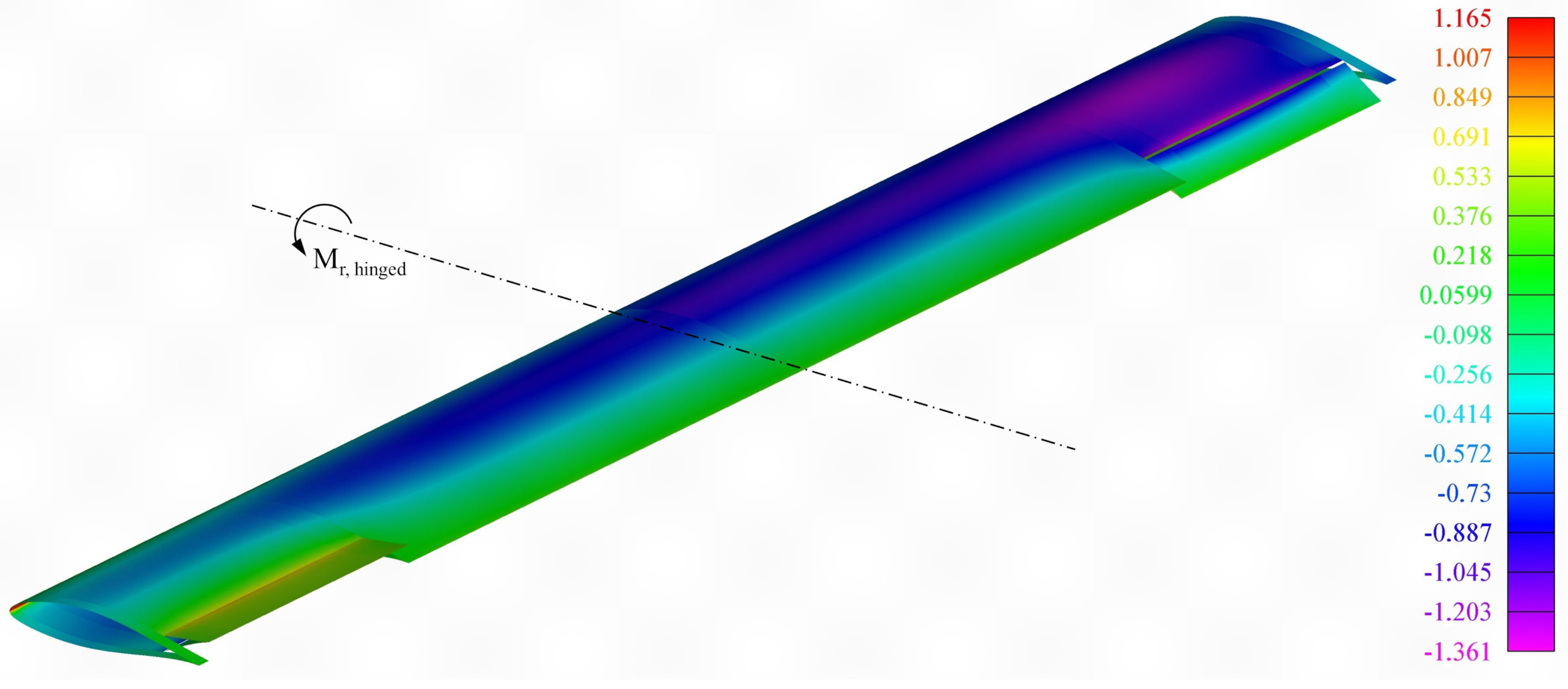
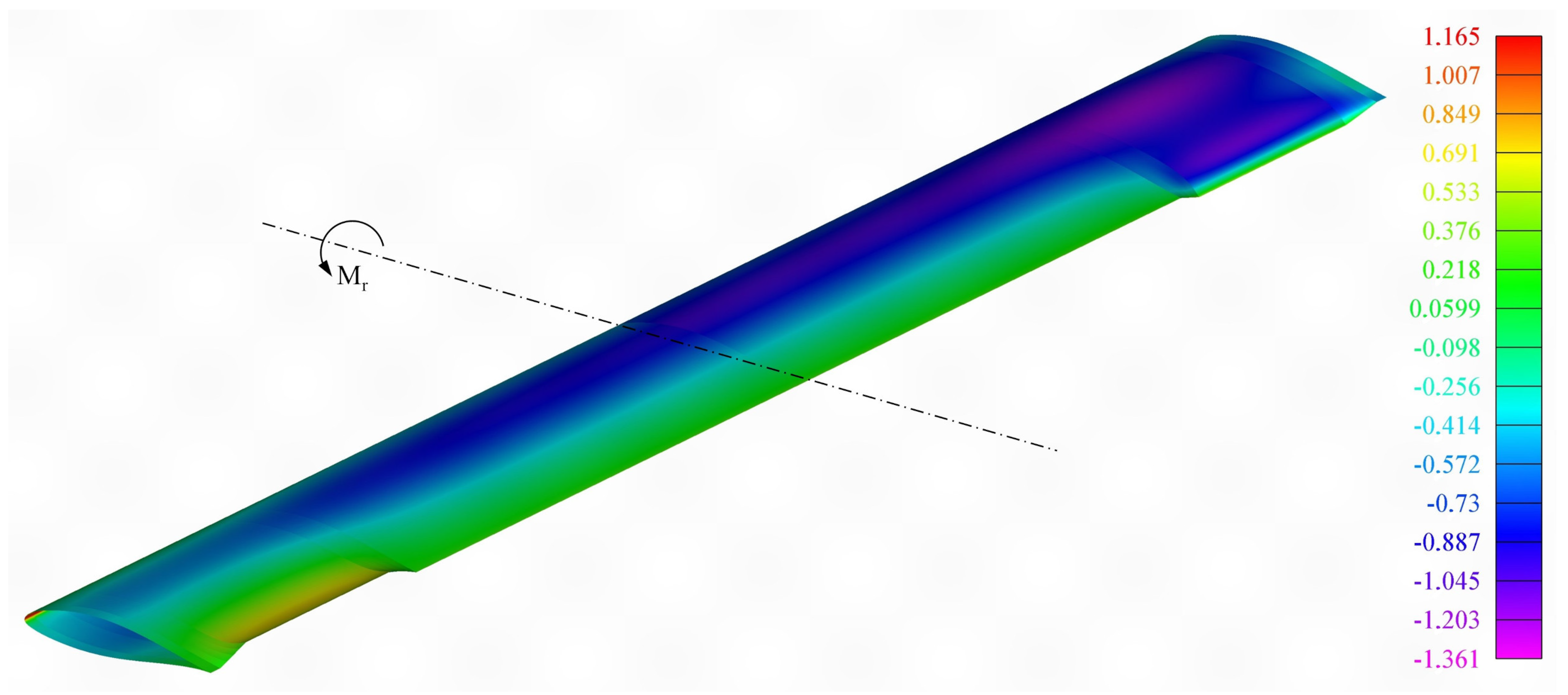
The same technique was used to automatically generate a structured mesh on the RW surface. The mesh was divided into wing sub-elements to delimit and identify the aileron region and the aerodynamic panels belonging to the aileron. After a convergence study, a mesh composed of 80 panels in a chordwise direction and 200 panels in a spanwise direction was selected. At the beginning, steady analyses were performed without the rotation of the ailerons, considering the reference design condition shown in
Table 1. The same table reports the wing reference surface value, the reference values for the aileron and the lift coefficient of the wing for two different angles of attack (
). After that, the same analyses were performed considering the maximum differential rotation of the ailerons
. The results in terms of pressure distribution over the entire wing are shown in
Figure 3 for a
of angle of attack.
Other aerodynamic results are shown in
Table 1. The aileron hinge-moment coefficient is computed for
and then for the maximum positive and negative rotation of the aileron. The hinge moment at the maximum positive rotation will be used for the computation of the reference actuation energy that corresponds, in the case of the hinged aileron, to the work performed by the aerodynamic forces during a rotation of
. The total moment computed around the roll axis
, due to the maximum differential rotation of the ailerons, represents the aerodynamic performance requirement that should also be guaranteed by the morphing aileron. Looking at the comparison between these results at two different angles of attack, (
and
), it can be noted that, while the hinge moment is slightly affected by the angle-of-attack variation, the maximum roll moment is achieved for
. For this reason, an angle of attack of
is used as reference trim condition.
The same aerodynamic code described above is used to compute the aerodynamic loads acting on the morphing aileron. The aerodynamic benefits due to the morphing, in terms of drag, flow separation and effects that these aspects have on the aileron deflection, should be analysed by higher-fidelity simulations, but this type of study is outside the scope of this article. The mid-fidelity aerodynamic solver adopted here is employed to estimate the morphing aileron deflections, the loads needed to achieve the roll-moment performance requirement and to compute the total energy required by the morphing aileron. The total energy is used as a morphing-device performance index and to predict the behavior of the actuation system to be coupled with the morphing aileron.
4. Design Optimization of the Morphing Aileron
The design of the morphing aileron proposed in this article is focused on the actuation system that drives the aileron to deform as expected, achieving the required performance, and, at the same time, to withstand the external loads. The controlled deformation of the structure under the effect of aerodynamic loads is the main task of a morphing device, such as the aileron under investigation. Quantifying this capacity, however, is more difficult than in the case of a traditional aileron that is free to rigidly rotate around its hinge axis. The most suitable way to quantify the action of a morphing device is through the total energy required to perform the morphing task: changing the wing configuration from its initial shape to the target shape to achieve the required performance, under the effect of aerodynamic loads. On the one hand, the target shape must be able to meet the aerodynamic performance requirements, on the other hand it must be feasible from the structural point of view. Once the target shape is defined, the total energy needed to obtain it can be computed and used to design the actuation system to be installed inside the morphing aileron. In the design of any morphing device, the actuation system, including its kinematics, is strictly related to the design of the deformable structure. The idea behind the work presented here is to embed the computation of the total energy inside an aero-structural shape optimization working on the definition of the target shape.
A multi-level approach is usually adopted by PoliMi for the optimal design of morphing devices based on compliant structures. The first level works on the definition of the optimal target shape. In the next levels, an ad-hoc-developed topology-optimization tool is used to define the optimal structural configuration which is able, once actuated, to deform itself matching the optimal shape coming out from the first level [
6]. The work described in the following sections focused only on the first level and, at the same time, on the design of the internal actuation system. The target shape is determined as the most efficient shape able to achieve the aerodynamic performance requirement and, at the same time, to minimize the total energy needed to deform the morphing structure and withstand the external aerodynamic loads.
4.1. Shape Representation
The key aspect of all shape optimizations lies in the selection of the most suitable geometry parameterization technique able to represent shape changes through a small but effective set of design variables. The method that is adopted in this work was originally proposed by Kulfan to perform aerodynamic shape optimization and to describe three-dimensional and analytically smooth geometries of several aircraft components, such as wing, body and nacelle. This method is called the class/shape function transformation (CST) technique [
35] and it is based on merging a shape function with a class function. The shape function is composed by tunable components represented by the Bernstein polynomials, while the class function is a non-linear function that mathematically defines a basic wing shape. Some years ago, PoliMi implemented an extension of this method able to identify an initial wing shape, starting from the original CAD model, and to introduce shape perturbations due to morphing in a feasible way, thus considering some constraints related to the structural behavior of the external skin [
36].
A generic wing geometry can be mathematically defined as follows:
where
and
are the dimensional coordinates obtained by multiplying the non-dimensional coordinates
and
by the local chord distribution
and the wing span
b, respectively. The leading-edge,
x, position expressed as a function of
is described by
. The
coordinate system used to describe the RW geometry is shown in
Figure 1. The wing geometry is considered to be divided into an upper and a lower surface. Both non-dimensional surfaces can be described as follows:
where
and
are the trailing-edge and the leading-edge vertical position expressed as non-dimensional functions of
. The non-linear class function is defined as
; the square matrix
contains the Bernstein polynomial components of order
m, which define a unit spanwise shape function; and the square matrix
contains the Bernstein polynomial components of order
n, which define a unit chordwise shape function. The rectangular matrix
is composed of the extra coefficients acting in the spanwise and chordwise direction, respectively. Therefore, the shape function is a two-dimensional function defined as:
. Considering the matrix
, each row defines a component airfoil, and the first and last rows contain the extra coefficients of the airfoils placed at the tips of the wing. The first and last columns are related to the leading- and trailing-edge boundary conditions and can be used to change their shape in the spanwise direction. When the CST technique is adopted to reproduce the shape changes due to the camber morphing, the square matrix can be partitioned into three sub-matrices: the first and last sub-matrices are related to the shape of the leading edge and the trailing edge, respectively, while the middle one is related to the shape of the wing box. When the CST technique is used inside a shape optimization working on a leading edge or a trailing edge with morphing capabilities, the extra coefficients of the first and last sub-matrices can be used as optimization variables. The extra coefficients contained in the middle can be used to satisfy the shape constraints due to the presence of the wing box, by a least-squares fitting. The mathematical formulation of this constraint represents the three-dimensional extension of the wing box implicit constraint described in [
36].
The CST parameterization technique described above is used to identify the original wing shape and then to introduce the shape changes due to the camber morphing. After both the original and the morphing shapes are defined, the same technique is suitable to describe the structural behavior of the morphing skin. The first and second derivative of Equation (
2) can be computed in a fully analytical way and this makes very efficient the calculation of the curvature
, at a generic point
of the wing geometry, and the length
L of a portion of the wing geometry in a specific direction. Since the skin follows the external geometry of the wing, these quantities can be used to compute the axial and bending strains of the skin when the wing shape changes due to the morphing.
Although the concept of curvature can also be applied to the three-dimensional geometry of the wing, in the case of this work it is convenient to use the concept of the curvature of a plane curve by defining specific directions as functions of the previously defined coordinates and . The reason for this is that the structural response is calculated starting from the curvature variation between two different three-dimensional surfaces, the undeformed and the morphing ones, and it is important that the curvature on the two surfaces is computed with respect to the same arc length.
Since the active camber morphing arises from a shape variation in the wing airfoils, it is convenient to use an arc length function
l defined in the chordwise direction, then by the intersection between the surfaces describing the wing and a plane of principal curvatures parallel to the
plane. This means the existence of a parameterization
such that the tangent vector
has a norm equal to one and is thus a unit tangent vector. For example, in
Figure 4, the arc length
l follows the upper skin of the morphing aileron and the lower skin is free to slide, enabling the deformation of the aileron. Since the CST surfaces are at least twice differentiable, the curve obtained by intersecting the surfaces with the plane containing the tangent vector is differentiable and the principal curvature on the airfoil planes can be computed as:
where primes refer to derivatives with respect to
l and
represents the spanwise location of the plane containing the tangent vector. The second formula of Equation (
3) enables a fully analytical evaluation of the curvature. In the case of a tapered wing or a deformation induced by a twisting skin, the component of principal curvature computed along the
direction should be composed with the principal curvature computed along the
direction. The component along
direction can be obtained through the curvature difference computed on the plane containing the tangent vector
.
When a morphing device is actuated, its external shape changes. The skin deformation is the result of its structural response and can be calculated in terms of stress
or strain
distribution over the skin surface. The strain, for example, can be considered as the combination of an axial and a bending component. The axial strain is a simple function of the length variation
calculated before and after the deformation for a portion of the skin in the direction of interest. In the same way, the bending strain can be computed as a function of the curvature difference between the undeformed and the target surfaces. As mentioned above, the curvature on the two surfaces is computed with respect to the same arc length. If the arc length is defined in the chordwise direction, so by the intersection between the CST surfaces and a plane parallel to the airfoil sections, the curvature on the two surfaces can be calculated using Equation (
3) and the curvature difference function is defined as follows:
where
and
are the curvature functions of the undeformed and the target surfaces, respectively. According to Kirchhoff plate theory [
37], the stress distribution
, defined as a function of the arc length and the skin thickness, is shown in
Figure 4 and can be computed as:
where
E is the Young’s modulus of the skin material,
is the corresponding strain distribution and
represents a local coordinate perpendicular to the arc length, with origin in the centre line of the skin thickness. The maximum bending stress or strain along the arc length can be calculated as:
where
is the the skin thickness as a function of the arc length. The bending strain and stress generated when the skin is forced to assume the target shape can be used for the computation of a part of the actuation energy.
4.2. Total Energy Computation
According to the energy methods applied to structural analyses [
37], the total actuation energy can be computed as a combination of the strain energy
U, required to deform the morphing skin, and the aerodynamic work
, needed to counteract the aerodynamic forces:
The energy is computed considering all parts of the skin. In the case of a trailing edge, for example, the contributions of both the upper and the lower skin is considered. Starting from the stress
and the strain
distribution of Equation (
5), and according to the mathematical quantities shown in
Figure 4, the parameterization method can estimate the strain energy
U as follows:
where
L is the skin length along the arc length,
V and
are the volume of the skin and
h is the skin length in spanwise direction. Equation (
8) for the strain-energy calculation is general, but it is here simplified assuming the morphing aileron, and all its structural properties are constant in the spanwise direction.
The work performed by aerodynamic forces during morphing deformation
can be computed as:
where
A and
are the skin surface area and
v and
are the volume generated by the skin during the deformation due to the morphing. All other quantities are shown in
Figure 4. The unit vector
is normal to the skin surface, while the unit vector
is tangent to the displacement
of each point along the skin during deformation. Each of these points forms a path of length
. The dot product
is equal to
, where
is the angle between
and
. When the skin is undeformed,
, while
when the skin achieves the target shape. The last step of Equation (
9) is valid under the assumption of linear variation in the pressure distribution
acting on the skin during deformation. The initial pressure distribution
, acting on the skin when it is undeformed, becomes
when the skin is deformed and achieves the target shape. The CST technique can be coupled with any aerodynamic solver to compute pressure distributions
and
. In this work, it is coupled with the in-house panel method, already described in
Section 3 for the calculation of the roll moment and the aileron hinge moment. Thanks to its analytical nature, the CST formulation is used for directly generating the aerodynamic mesh, saving computational time in the pre-processing phase.
What is important to point out is that the total actuation energy
is valid for any actuator installed inside the morphing device, while the actuation force or the actuation torque depends on the position of the actuator. However, the CST parameterization technique can estimate the actuation force by, for example, dividing the actuation energy by the actuator stroke, once the kinematics of the morphing solution is known. According to the linear slider installed on the lower skin of
Figure 4, the actuation stroke, requested by the morphing aileron to achieve the target shape, can be computed as the difference between the length of the lower skin before and after the morphing deformation.
4.3. Design Optimization Procedure
The procedure for the design of the morphing aileron proposed in this article consists of a design optimization aiming at the definition of the most energy-efficient shape, subject to aerodynamic and structural constraints that account for the aircraft roll-manoeuvre requirements and for the structural behaviour of the morphing skin, respectively. The CST technique and the total energy computation described in
Section 4.2 are embedded into the optimization procedure and used to minimize the total actuation energy
. The final solution is strongly affected by the morphing skin, which plays a key role in the definition of the shape that the aileron can assume once it is actuated. Considering that its structural behavior allows the optimization process to work immediately, morphing shapes are feasible from the structural point of view without the need to iterate next design phases. Constraints limiting the structural response of the skin are based on a constant sross-section length (CCL) strategy that forces the skin to keep the axial strain equal to zero and the bending stress under the allowable limit of the material. This strategy does not require finite element analyses, because the stress or strain computation is embedded into the CST formulation described in
Section 4.1, and allows that the aerodynamic analyses are also performed only on feasible morphing shapes.
The optimization variables for the introduction of the shape changes into the morphing aileron are selected among the CST parameters. Since each CST parameter can spread the shape variations over the entire domain
, preserving the continuity and the local smoothness of the wing geometry, two optimization variables, shown in
Figure 5, are enough to describe any possible deflection of the morphing aileron: the trailing-edge equivalent rotation and the tail-angle variation.
The equivalent rotation
is an index of how much the trailing edge moves up and down, and the airfoil tail-angle variation
is an index of how much the airfoil curvature changes in the trailing edge area. According to the CST parameters shown in
Figure 4, the trailing-edge equivalent rotation can be defined as:
where
and
are the trailing-edge vertical positions of the undeformed and the morphing aileron, respectively;
is the chord length of the morphing airfoil; and
is the chordwise position where the fixed part of the skin ends and the deformable skin begins. The airfoil tail-angle variation can be simply defined as:
where
and
are the airfoil tail angles of the undeformed and the morphing aileron, respectively. The airfoil-tail-angle parameter is strictly related, through the trailing-edge boundary conditions mentioned in [
36], to the extra coefficients contained in the last column of the matrix
, for both the upper and the lower surfaces describing the wing geometry. The tail-angle variation of a morphing airfoil is generally bigger than its equivalent rotation. The total number of optimization variables can be a multiple of the two variables described above, depending on the spanwise deflection law to be obtained. For example, if a constant deflection is required, two optimization variables are enough. Otherwise, if a liner deflection is required, four optimization variables can be used to independently deflect the two airfoils placed at the tips of the aileron and to twist it.
Once the number of optimization variables has been defined, the optimization procedure works on them to minimize the total actuation energy during the roll manoeuvre. The optimization scheme consists of two nested optimization loops: the inner one produces only feasible morphing shapes, the outer one performs the aerodynamic evaluation. In this way, only morphing shapes that meet all the structural and mechanical constraints are considered during the aerodynamic computation. The complete optimization problem can be formulated as follows:
Minimize:
subject to:
where
is the roll moment produced by a symmetrical deflection of the morphing aileron, while
represents the performance requirement. In the work presented here, it is the roll moment computed in
Section 3 and produced by a rotation of
of the hinged ailerons. The aerodynamic field around the wing equipped with the morphing aileron, and the corresponding roll moment, are computed by the same in-house aerodynamic code described in
Section 3 and used for the calculation of the aerodynamic work in
Section 4.2. The shape changes introduced by the optimization are transferred to the aerodynamic mesh through the analytical interface based on the CST formulation.
The second term among the optimization constraints represents the so-called wing-box implicit constraint which is described by
distinct real points placed in the wing region that must be kept undeformed. The matrix
is the
reduced CST Vandermonde matrix, where
r is the number of extra coefficients that the optimization works on, and
is the corresponding
vector. The unique solution of this linear system is equivalent to solving, in the least-squares sense, the over-determined system containing the
extra coefficients not affected by the optimization and reorganized in the vector
. The
r extra coefficients for each row of the matrix
are related, through the trailing-edge boundary conditions, to the two optimization variables described above and that affect the aileron shape. The third constraint defines the extension of the wing region that must be kept undeformed: in the case of this work, the procedure works on the morphing aileron, then the chordwise extension goes from the leading edge to the point where the deformable skin begins. The fourth term represents the inflatable term that is used to limit the internal-wing-area variation
. This constraint, combined with the structural constraints acting on the skin, is very effective in avoiding unfeasible morphing shapes. Usually, the maximum percentage variation allowed for an aileron is 20% (
) of the internal undeformed area
A. The fifth constraint aims to prevent variations in the upper skin length
to avoid axial stresses inside the skin. According to the kinematic solution shown in
Figure 4, for a linear slider connecting the bottom skin to the fixed part of the wing, the sixth constraint defines the maximum actuator stroke in terms of percentage variation (
) of the local chord. The seventh constraint is used to limit the maximum curvature variation
defined in
Section 4.1. This term allows to limit the bending stress inside the skin. The last two terms represent the upper and lower bounds applied to the optimization variables.
5. Results
The optimization procedure described in
Section 4.3 was applied to the RW presented in
Section 2. The objective was to replace the hinged aileron with a morphing aileron able to minimize the actuation energy, while providing the same roll moment produced by the maximum hinged aileron rotations of
. The aim of this work is to minimize the actuation energy, in parallel with the adoption of the kinematics shown in
Figure 4, to allow the installation of an actuation system as compact and lightweight as possible. One of the constraints for the aileron substitution is that the wing configuration of
Figure 1 does not change, except in the aileron region, where the room taken up by the morphing aileron must be the same as the traditional one in both spanwise and chordwise directions. The geometry of the morphing aileron is represented in
Figure 6, which shows how the four meters of spanwise extension include the transition regions that are necessary to guarantee the gapless continuity of the morphing aileron, not only in chordwise, but also in spanwise directions. As in the case of the hinged aileron, the available room to install the actuation system inside the wing ranges from
to
, with the difference that the space inside the morphing aileron is empty and does not contain the hinge, so it can be used for a more flexible actuator installation.
5.1. Optimal Morphing Aileron Deflections
The optimal design of the morphing aileron was carried out by applying the optimization problem
12 to the wing geometry of
Figure 6.
Firstly, the design of the morphing aileron was performed, exploiting the possibility to twist the aileron, to design, in a different way, the two airfoils placed at the tips of the aileron. However, after a lot of analyses, no benefit was obtained compared to a constant deflection law in the spanwise direction. For this reason, only two optimization variables were selected, according to the symmetrical deflection of the left and right morphing ailerons. The equivalent rotation was bounded between and , while the airfoil tail-angle variation was bounded between and . The maximum curvature variation was set to , according to a skin made of a glass-fiber (GF) composite material.
The optimal morphing aileron shape that came out of the optimization process is shown in
Figure 7. The corresponding values of the optimization variables are
, for the upward and downward deflections. This morphing configuration allows to achieve a roll moment equal to the roll moment produced by the hinged aileron, in the same aerodynamic condition, with a first important benefit in terms of smaller equivalent rotation (
), compared to the hinged aileron rotation (
). The aileron deflection able to minimize the actuation energy is the one that increases the airfoil tail-angle variation, and then the airfoil curvature in the trailing-edge area, up to the limit values set by the bounds. A first lesson learned is that this result, considering the morphing skin made of GF, is valid for any thickness
t value assigned to the skin.
Once the optimal deflections are defined, it is possible to compute both the trajectories’ length
of the points belonging to the skin during deformation and the dot product
, as functions of the arc length. The trajectories’ length of the upper and lower skin, for the downward and upward deflections, are shown in
Figure 8, while the corresponding dot products are shown in
Figure 9. According to the linear slider connecting the bottom skin to the fixed part of the wing, the actuator stroke can be easily obtained by the CST parameterization technique that allows the identification of how much the lower skin becomes shorter when the aileron deflects downwards and how much the lower skin becomes longer when the aileron deflects upwards. Looking at the trajectories’ length of the lower skin, the actuator stroke for the downward and upward deflections is represented by the values assumed at
, which is the position of the linear slider along the arc length. The actuator stroke
value is about
when the morphing aileron deflects downward and +38 mm when the morphing aileron deflects upward. Looking at the dot products, it is possible to see that, while the angle
between the unit vector
and the unit vector
is equal to
for all the points belonging the upper skin, the same angle is close to
where the lower skin slides parallel to the airfoil and then perpendicular to the direction of aerodynamic forces. Where the angle is equal to
, the displacement
is tangent to the aerodynamic forces.
The aerodynamic results in terms of pressure distribution over the entire wing, equipped with the optimal morphing aileron, are shown in
Figure 10, in the same aerodynamic conditions considered for the hinged aileron. The pressure distribution due to the optimal morphing deflection is compared with the pressure distribution due to the maximum hinged aileron rotation and with the pressure distribution over the clean wing without aileron rotation. The comparison is shown in
Figure 11 and
Figure 12 for the upper and lower wing surfaces, respectively. Looking at these figures, it appears clear how the morphing deflection is able to better spread the pressure over the entire chord length.
5.2. Parametric Study and Energy Computation
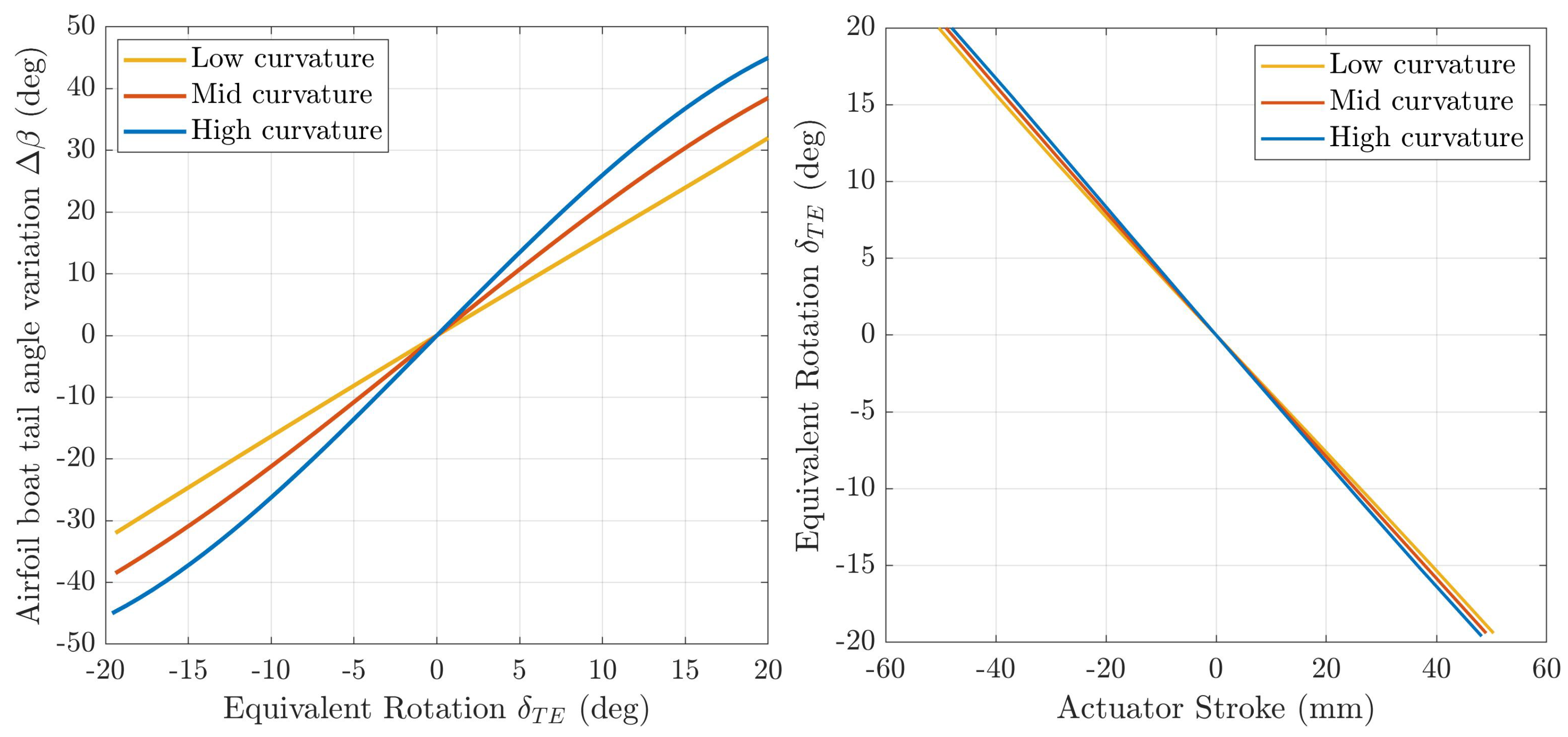
The optimal morphing aileron presented above was obtained by assigning reasonable structural properties to the skin. However, the optimization result can change depending on the skin thickness and the material that the skin is made of. For this reason, a parametric study was carried out with respect to these two parameters. Three different families of aileron shapes, corresponding to three different relationships between the two optimization variables, were defined and they are shown in
Figure 13 (on the left).
The same figure (on the right) shows the corresponding kinematic relationships between the actuator stroke and the morphing trailing-edge deflection in terms of equivalent rotation.
Figure 14 shows the corresponding maximum downward and upward deflections (
of equivalent rotation). The three different families are characterized by three different curvature levels in the trailing-edge region: low curvature, mid curvature and high curvature. Each of these shapes is feasible from the structural and mechanical point of view thanks to the constraints functions described in
Section 4.3: the upper skin is forced to keep its length constant, that is, equivalent to keep the axial stress equal to zero in the upper skin, while the lower skin is free to slide, according to the installation of a linear actuator inside the wing. The optimal deflection presented above belongs to the high curvature family.
The parametric study was carried out by computing the equivalent rotation, which allows each deflection family to achieve the same roll moment as the one produced by the hinged aileron. The high-curvature deflection family needs an equivalent rotation of
, the mid-curvature family an equivalent rotation of
and the low-curvature family an equivalent rotation of
, to achieve the roll moment requirement. For each of these equivalent rotations, the total energy was calculated considering three different values of skin thickness (1 mm, 2 mm and 3 mm) and two different materials for the skin: aluminium alloy and glass fiber composite material (Fabric 0/90 type S high performance). The results, in terms of total energy, are reported in
Figure 15, where they are compared with the energy required to rotate the rigid hinged aileron of
, and calculated starting from the hinge-moment values shown in
Table 1.
In general, it can be stated that the energy required by the morphing aileron to counteract the aerodynamic forces is smaller compared with the energy required by the hinged aileron. This reduction is partially lost due to the strain energy, but the total actuation energy of the morphing aileron is less than the energy needed for the rotation of the hinged aileron, for any considered value of thickness, for any considered material of the skin and for any deflection family. Then, the energy increases with increasing skin thickness when a specific deflection family is considered, and this is valid for any material. In general, however, it cannot be stated that the total energy decreases when the airfoil tail-angle variation increases and the equivalent rotation of the aileron decreases. Simply going from the low-curvature family to the high-curvature family, the total energy decreases if the aluminum alloy is not combined with too-high values of thickness, so long as the structural stiffness of the skin is not too high. Considering the three morphing deflections able to provide the required roll moment for each curvature family,
Figure 16 shows the curvature difference distributions as a function of the arc length, which is strictly related to the strain distribution along the upper and lower skin by Equation (
6), for the downward and upward deflections. As it is logical to expect, the strain level inside the skin is higher for deflections with a greater airfoil tail angle and this explains the greater deformation energy of the higher curvature families in
Figure 15. However, the maximum value of curvature variation is much below the limit value imposed in the optimization constraints.
Considering the three downward deflections able to provide the required roll moment,
Figure 17 shows the aerodynamic comparison between the RW, the maximum rotation of the hinged aileron and the three morphing deflections, in terms of the pressure coefficient distribution around the airfoil placed at
of the aileron span.
The optimal morphing deflections belong to the high-curvature family and it allows to achieve a roll moment equal to the roll moment produced by the hinged aileron, with a double benefit in terms of a smaller equivalent rotation ( instead of ) and a smaller actuation energy: lower in the case of skin made of aluminium alloy and in the case of skin made of fiber glass.
5.3. Preliminary Design of the Morphing Aileron Actuation System
According to the installation of a linear slider connecting the lower skin to the fixed part of the wing, the actuator linear force required to achieve the optimal morphing deflection could be computed as
, where
is the actuator stroke. However, this is only the mean value of the actuation force during actuation, and the maximum linear force should be computed starting from the static force needed to keep the aileron fixed in the undeformed condition, under the corresponding aerodynamic loads. The peak force can be calculated starting from the integral of the force, which must be equal to the total energy
, assuming a linear trend as a function of the actuator stroke. From the equilibrium, the static force that must be applied to the linear slider to keep the aileron fixed in the undeformed condition is equal to 12,690 N. To generate an actuation energy equal to the total energy of 777.8 Nm, as computed in
Section 5.2, the actuation law must be like that shown in
Figure 18.
The maximum linear force required by the hinged aileron can be simply calculated from the maximum value of the hinge moment reported in
Table 1. Starting from the maximum aileron rotation of
and from the position of the hinge axis, it is possible to compute the maximum stroke for the actuator connected to the hinged aileron. The comparison between the design requirements for the actuators to be installed in the hinged and the morphing ailerons are summarized in
Table 2. The maximum linear force required by the morphing aileron is much smaller than the maximum linear force required by the hinged aileron for two main reasons. First of all, the total energy required by the morphing solution is smaller. Then the two different kinematics make the actuator stroke for the morphing solution greater than the stroke for the hinged solution.
The maximum force required by the actuation system to deflect the morphing aileron and achieve the optimal shape is 6000 N which becomes 9000 N when including a safe factor of .
The selection of the most suitable actuator depends on the design requirements that have just been defined above, on the available space inside the wing and the number of actuators to be installed inside the wing. Since the actuation stroke must be constant along the aileron span, the positioning of the actuators should be symmetric about the centreline of the aileron and at least two actuators should be installed inside the wing. Moreover, the total actuation force previously obtained must be multiplied by the safe factor and divided by the number of actuators minus one, to consider the case of a failure. Therefore, at least three actuators must be installed along the aileron span. Looking at the commercially available actuators, an electromechanical linear actuator was selected in order to install four actuators inside the wing. The selected actuator allows to obtain both the positive and negative strokes required to achieve the optimal upward and downward deflections, corresponding to
of equivalent rotation, and perfectly fits the clearance requirements.
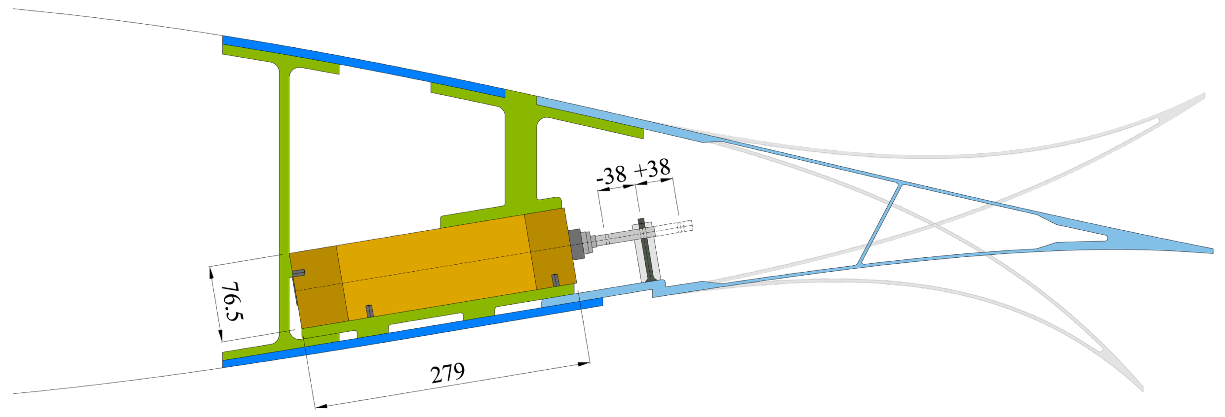
Figure 19 shows the installation of the actuators within each of the four airfoil sections, together with the main measurements and the maximum stroke. Each actuator linear guide is connected to the wing structure at four points: two points along the lower skin, one point on the rear spar and one point on the secondary spar, which defines the portion of deformable skin.
The installation of the four actuators along the aileron span and the relative distances between them are shown in
Figure 20, where it is possible to see the CAD model of the complete actuator which is mounted in parallel, including the linear guide and the piston rod, the parallel unit, and the motor (in red).
According to the actuator design requirements shown in
Table 2, the morphing solution needs 40% less actuation energy and 45% more stroke. The combination of these two factors results in a maximum required force that is less than half of the linear force required by the hinged aileron to achieve the same performance in terms of roll moment. This result has a strong impact on the size and weight of the overall actuation system, which makes the morphing solution much more efficient.
6. Conclusions
An energy-based optimization procedure, based on a parameterization technique able to describe the shape changes in morphing devices, was presented and used for the design of a morphing aileron coupled with the actuation system needed to deform it, while counteracting external aerodynamic loads. The energy-based approach proved to be effective, so it will be integrated into the multi-level and multi-objective procedure adopted by PoliMi for the design of compliant structures and extended to the design optimization of all morphing devices, even when the actuation aspect is not the focal point of the design. Indeed, taking into account the total energy minimization together with other design objectives improves the achieved morphing solutions, making them more feasible.
The optimal morphing aileron that came out from the procedure presented in this paper was compared with the traditional solution mounted on the reference wing. The results showed that the morphing aileron allows achieving the same roll-manoeuvre requirement with three benefits, in terms of smaller equivalent rotation, lower actuation energy and the smaller size and weight of the overall actuation system.
One of the advantages provided by morphing devices is related to the deformation capabilities that allow to continuously change the wing shape without generating any gap. However, the aerodynamic benefits related to the morphing solution should assess using high-fidelity aerodynamic tools, such as RANS simulations, but this task is outside the scope of this paper, which is focused on the design and benefits of the actuation system. Since the effects of the flow separation around the aileron cannot be considered completely negligible in the flight condition considered, the deflection difference between the morphing aileron and the conventional hinged solution could be much greater, as well as the aerodynamic benefits of the morphing solution.
After the aerodynamic assessment, the design and manufacturing of a morphing aileron large demonstrator is planned, to perform a numerical/experimental validation campaign. PoliMi has just concluded a similar activity performed on the full-scale prototype of a morphing droop nose, within the framework of the Clean Sky 2 REG-IADP AirGreen 2 (AG2) European research project. High-lift morphing devices are actuated very slowly, so they are designed without considering dynamic design requirements. In the case of a morphing aileron, the key aspect that is required to be studied is the dynamic interaction between the morphing aileron compliant structure being designed and the actuator used to deflect it. The design requirements of a morphing aileron, in terms of bandwidth, should be met considering the dynamic coupling between the flexible structure and the actuation. The morphing aileron is to be designed in such a way that the actuator provides the required bandwidth and the structure is faster, so the frequency of its first vibration mode is greater than the bandwidth. In such a context, the numerical/experimental validation should guarantee a reliable simulation of the coupling of the compliant structure with the actuation system.
In order to combine the coupling of the compliant structure with the actuation, and the RANS simulations mentioned above, a virtual aeroelastic test has been conceived. It exploits the tools developed at PoliMi in the field of computational aeroservoelasticity, based on high-fidelity CFD simulation. The aerodynamic solver is the open-source code SU2 that is going to be coupled with the commercial software Abaqus within an in-house fluid–structure interaction (FSI) framework. In this way, the tools can exploit Abaqus capabilities in nonlinear structural analyses, which are necessary to correctly represent the morphing-structure behaviour.


