Abstract
Reinforced concrete (RC) walls are designed to carry vertical and horizontal loads which may need to be rehabilitated and strengthened to enhance their load-bearing capacity due to increased loading demands, environmental factors, or lateral forces. This study proposes strengthening RC walls using sustainable engineered cementitious composite (ECC) material reinforced with welded steel mesh (WSM). An experimental program was carried out on six RC walls strengthened using the proposed method to explore the effects of the thickness of the ECC layer, and the number of WSM on their axial performance. The ECC strengthening layer was reinforced with one, two, and three layers of WSM. The thicknesses of the ECC layer varied from 10 mm, 15 mm, and 20 mm. It was found that the proposed strengthening method significantly improved cracking control, elastic stiffness, energy absorption, failure modes, and ultimate load capacity. The strengthening technique improved the ultimate loading capacity between a range of 8% to 41%. Similarly, the energy absorption of the wall increases between a range of 60–175%. In addition, nonlinear finite element models were designed and validated against the experimental data. The validated model was used to perform a parametric study.
1. Introduction
Reinforced concrete (RC) wall is a crucial structural system of building structures that carry vertical and resist lateral forces. However, the durability and performance of RC walls can degrade over time due to factors such as material aging, environmental exposure, and severe loading events like moving loads. This degradation can compromise the structural integrity of buildings, necessitating the strengthening process to recover and upgrade their load-bearing capacity. Moreover, the need for retrofitting and strengthening RC walls has grown in recent years due to stricter building codes and the demand for more resilient structures in the face of increasing natural disasters. Such strengthening involves various techniques aimed at improving their mechanical behavior, enhancing their ability to withstand gravity loads in addition to extending their service life. Researchers have focused on developing and optimizing various strengthening methods that are sustainable, cost-effective, and capable of minimizing disruptions to existing structures during application. Understanding the mechanisms of RC wall failure and the effectiveness of different strengthening strategies is critical for ensuring the safety and longevity of structures in both new construction and rehabilitation projects [1,2,3,4,5,6]. Common strengthening methods include the use of additional steel reinforcement, wrapping of fiber sheets, or increasing the wall’s cross-section. Each of these methods offers unique advantages, depending on the specific needs of the structure, such as increased vertical or lateral capacity, enhanced ductility, or improved confinement. The strengthening process can be applied through externally bonded reinforcement (EBR), or near surface mounted (NSM) [7,8,9].
Significant works on the applications of fiber-reinforced polymer (FRP) in strengthening RC walls have been reported in the literature [2,10,11,12,13,14,15,16]. The ultimate performance of axially loaded reinforced concrete (RC) walls strengthened using glass fiber-reinforced polymer (GFRP) was investigated by Andrea et al. [17]. It was found that significant strength gains can be achieved by wrapping the walls with GFRP. Although the number of transverse plies had little effect on axial strength, it notably improved ductility. The axial compression behavior of a novel composite shear wall was carried out by Wang et al. [18]. It was reported that the axial compression capacity of multi-ribbed composite walls, featuring reactive powder concrete-filled steel tubular columns, improved with increased block strength and tube thickness. Bastami et al. [19] explored the behavior of special RC shear walls under lateral and axial cyclic loads. Jin et al. [1] tested the effects of carbon fiber-reinforced polymer (CFRP) sheets for strengthening of RC walls in shear. The results show that CFRP sheets improved the energy absorption and failure modes of the tested RC walls.
Engineered cementitious composite (ECC) is a sustainable building material increasingly used for rehabilitating RC structures. ECC offers significant improvements in tensile and compressive strengths, as well as ductility [20,21,22,23,24]. ECC offers superior ductility and crack control, which extend the durability of concrete structures [25,26,27,28]. Hossain et al. [29] investigated ECC modular framed shear wall systems under lateral cyclic loading. It was reported that ECC significantly enhanced the shear capacity of the infill wall and the overall framed shear system. Studies on ECC shell-RC columns under axial compression carried out by Ding et al. [30] demonstrated improvements in both ductility and energy absorption. Zeng et al. [31] found that adding ECC layers to RC columns increased load-bearing capacity by 53%, mitigating brittle failure. Cui et al. [32] examined the seismic performance of precast wall-beam joints with ECC post-cast zones, showing that a finite element analysis method accounting for ECC properties and reinforcement slip achieved high accuracy and was suitable for engineering applications. Ding et al. [33] conducted an analytical study on the seismic behavior of ECC shell-RC columns, analyzing how design parameters such as ECC height, shell thickness, and material properties impact seismic performance through finite element analysis. Hu et al. [34] investigated the application of ECC in RC-coupled shear walls numerically and provided recommendations for its effective use, focusing on its tensile properties and appropriate application range in traditional RC structures.
Incorporating welded steel wire mesh (WSM) or glass fiber wire mesh (GFWM) has also been applied in retrofitting the RC structures to further improve the tensile properties of NSM concrete or composite layers such as ECC. Erfan et al. [35] examined the compressive performance of RC walls using expanded steel wire mesh (ESWM) and GFWM reinforcement. Results show that expanded steel wire mesh reinforcement improved ductility, while glass fiber mesh provided better performance in terms of first cracking load, serviceability load, load-bearing capacity, and energy absorption. Hamoda et al. [28,36] examined the applications of WSM and GFWM in strengthening RC deep beams. It was found that the number of WSM and GFWM affects the performance of RC deep beams.
Regardless of the extensive research carried out on RC walls strengthened with CFRP sheets, their poor fire performance and high cost still hinder their wide application in strengthening RC walls. Further studies should be conducted to explore other alternatives of sustainable materials for strengthening RC walls. The use of ECC reinforced with WSN can be an excellent sustainable approach to strengthening RC walls due to their ease of construction, cost, and excellent fire performance compared to CFRP. However, research on various strengthening techniques for RC walls using flowable ECC reinforced with/without WSM arranged in both orthogonal directions is still limited. This study is concerned with an experimental and numerical investigation into the strengthening of RC walls under gravity loads using an ECC layer, with and without WSM reinforcement in both orientations. Finite element models (FEMs) were designed and validated with the test results. A parametric study was also conducted to explore additional influencing factors.
2. Experimental Program
2.1. Specimens’ Details
All RC walls had identical dimensions with a height (h) of 750 mm and a width (b) of 400 mm, with a thickness (t) of 80 mm as shown in Figure 1. The reinforcement arrangement of the steel reinforcements (vertical and lateral) ensures the structural integrity of the RC wall. The adopted reinforcement layout was chosen to ensure stable and controlled failure mechanisms. All walls were reinforced with vertical and horizontal reinforcement as shown in Figure 1a. The vertical reinforcement consisted of two bars with a diameter of 16 mm located at each of the two small sides along with two bars with 12 mm located at each large side. It should be noted that the diameter of the corner bars was deliberately designed to be large compared to the specimen thickness to avoid premature yielding of longitudinal reinforcement. All the specimens had sufficient cover concrete to tackle durability issues of concrete, and no adverse effects related to bar congestion or cover splitting were observed during experiment. The horizontal reinforcement consists of deformed bars with 8 mm diameter provided with standard 135° end hooks, in accordance with conventional confinement and anchorage requirements, with 100 mm spacing along the height of the wall shown in Figure 1a.
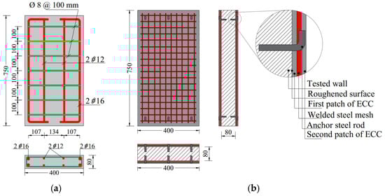
Figure 1.
Geometric and reinforcement details of tested walls: (a) master wall and (b) strengthened walls. (Units: in mm). Note: Schematic illustration (not to scale).
The test variables considered in this study include the thickness of the ECC layer, and the number of welded steel meshes (WSM). Table 1 provides three distinct groups (G1, G2, and G3) with different test wall IDs, studied parameters, ECC layer thickness, and the number of WSM. Group G1 acted as the reference group. Group G2 assesses the impact of different ECC layer thicknesses and a single layer of welded mesh. Group G3 evaluates the effect of increasing the number of welded steel meshes in ECC layers. It should be noted that ECC layer was applied to both faces of the specimens. The reported ECC thickness referred to in Table 1 refers to the thickness of the layer applied on each individual face. Thus, applying ECC will result in a total section thickness increase equal to twice the thickness (80 mm + 2 × thickness of ECC layer listed in Table 1).

Table 1.
Details of the tested walls.
The master group (G1) comprised two walls were: W0, WD0-E10. This group serves as the master or control group. The reference wall (W0) did not feature any strengthening. The strengthened wall (WD0-E10) had an ECC layer with a thickness of 10 mm with no WSM as an additional reinforcement. The second group (G2) focused on the effect of applying a strengthening process through the EBR technique using an ECC layer with different thicknesses reinforced with/without one layer of WSM. This group included W0, WD0-E10, WD1-E10, and WD1-E15 as shown in Table 1. Along with two walls, W0 and WD0-E10, described in the master group; the two walls WD1-E10 and WD1-E15 were strengthened using an ECC layer with thicknesses of 10 mm and 15 mm, respectively, reinforced with one WSM for both walls. The third group (G3) investigated the effect of ECC layers reinforced with varying numbers of WSM. This group included three walls: WD1-E20, WD2-E20, and WD3-E20, together with the master wall W0. The ECC layer was set with a constant thickness of 20 mm for all walls except that it was reinforced with one, two, and three WSM for walls WD1-E20, WD2-E20, and WD3-E20, respectively.
2.2. Material Properties
Two concrete types were used in this study. One of them was the normal concrete (NC) type used for constructing all walls, while the other type was ECC employed for strengthening layers. As mentioned earlier, ECC strain-hardening behavior under tension with multiple fine cracking, which is essential for controlling crack width and enhancing torsional resistance for the proposed strengthening scheme. Table 2 provides the mix proportion and compressive strength of the two types. It should be noted that excessive fiber volume and ultra-dense matrix can cause a reduction in workability, resulting in limited applicability for the strengthening scenarios. Based on the trials, the adopted mix design of ECC balances between the fiber volume and optimized matrix composition in order to achieve a better flowability and ease of placement around welded steel mesh and existing concrete surfaces. Therefore, the selected ECC mixture balances between the practicality and mechanical properties desired for strengthening purposes. The diameter of the PP was 39 µm and a length of 10 mm. The tensile strength and the elastic modulus were 950 MPa, and 44.5 GPa [37].
Table 2.
Mix proportion and compressive strength of the used concretes.
For each concrete type, three cylinders of 150 mm × 300 mm were tested to obtain the compressive strength of concrete (fc′) in accordance with ASTM C39/C39M [38]. Uniaxial tensile tests were carried out to measure the tensile strength of concrete as shown in Figure 2. The compressive strength of NC and ECC was 32 MPa and 67 MPa, respectively. Figure 3a,c presents the compressive stress–strain relationship for the two types of concrete along with the simplified curves used for the numerical modeling. The tensile stress–strain relationship of NC and ECC is shown in Figure 3. The tensile strength of NC and ECC was 3 and 4.5 MPa, respectively.
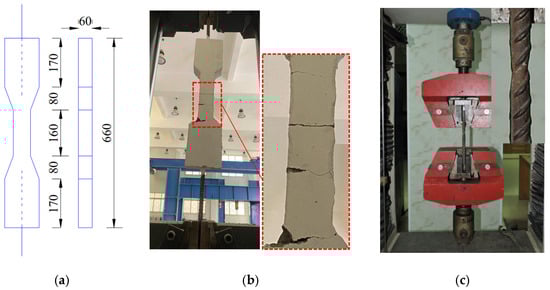
Figure 2.
Direct tensile tests: (a) dimensions, (b) ECC, and (c) steel bar.
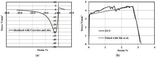
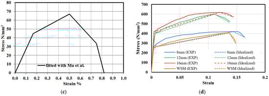
Figure 3.
Stress–strain curves of: (a) normal concrete, (b) ECC under tension, (c) ECC under compression, and (d) steel elements.
Table 3 summarizes the material properties of the steel elements obtained from the direct tensile test shown in Figure 2. The uniaxial tensile stress–strain curves of the steel elements are shown in Figure 3d. The yield/ultimate strengths were measured as 260/425, 402/599, 417/620, and 245/405 for steel bars with a diameter of 8 mm, 12 mm, 16 mm, and WSM with 4 mm diameter, respectively. Figure 3d also represents simplified curves for the steel materials used for numerical modeling.
Table 3.
Properties of steel elements.
2.3. Strengthening Procedure
After 28 days of curing, the strengthening of all the RC walls was implemented in the steps described in Figure 4. Firstly, in order to ensure good bonding of the wall’s surface to the strengthening materials, the outer surface was grained in inclined intersected paths as shown in Figure 4a. Secondly, 90° bent steel bars with 10 mm diameter set as shear connectors were embedded with chemical epoxy in the adapted wall’s surfaces as shown in Figure 4b,c. Thirdly, the welded steel mesh shown in Figure 4d was assembled just over the wall’s surface covering the whole area as shown in Figure 4e. The fourth step was to recover the outer surface with ECC filling spaces and cavities Figure 4f. The recovered surface with the new ECC layer reinforced with WSM was finally leveled as shown in Figure 4g.
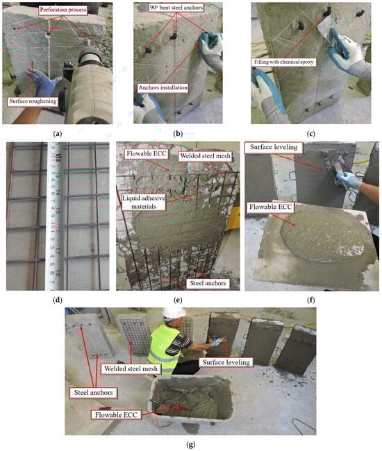
Figure 4.
Strengthening of the samples: (a) surface adapting, (b) installation of steel anchors, (c) epoxy application for anchors, (d) the used welded steel mesh, (e) strengthening elements, (f) the used flowable ECC and (g) surface leveling.
2.4. Testing Setup and Procedure
The experiment was conducted at Kafr El-Sheikh University, Egypt. Figure 5 illustrates the test setup of the samples. The specimens were painted in white paint for a better visualization. The hydraulic machine could exert forces up to 2500 kN on each tested wall. Rectangular caps were used to attach to both ends to facilitate a uniform load distribution as shown in Figure 5. A Linear Variable Displacement Transducer (LVDT) was used to record vertical measurements as shown in Figure 5. The walls were incrementally loaded to collapse during testing, with continuous monitoring of response. At each load stage, cracks were observed for reference, and vertical displacement readings were logged electronically.
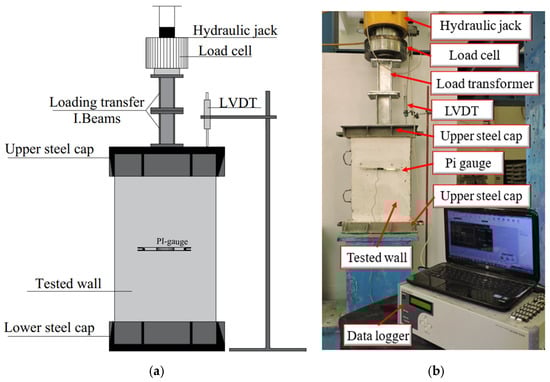
Figure 5.
Test set-up and details of the instrumentations: (a) schematic of tested wall and (b) image of the wall during the test.
3. Test Results and Discussion
3.1. Crack Pattern and Failure Mode
Figure 6, Figure 7 and Figure 8 provide an analysis of the failure modes and crack patterns for the three groups tested under static monotonic loading up to collapse.
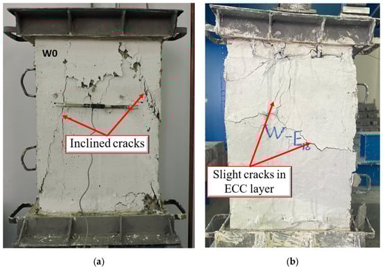
Figure 6.
The failure mode of the master group: (a) wall W0 and (b) wall WD0-E10.
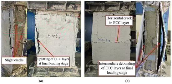
Figure 7.
Failure modes of group G2: (a) wall WD1-E10 and (b) wall WD1-E15.
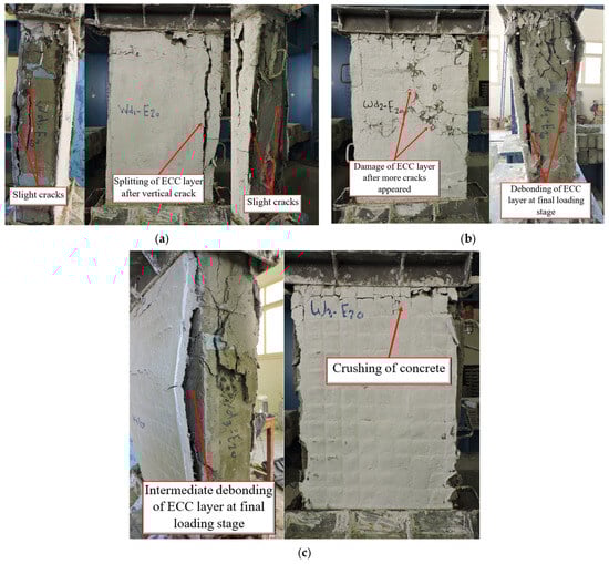
Figure 8.
Failure modes of group G3: (a) wall WD1-E20, (b) wall WD2-E20, and (c) wall WD3-E20.
For the master group, including walls W0 and WD0-E10, the crack pattern is shown in Figure 6. W0 without an ECC layer shows the inclined splitting cracks indicating the diagonal tension occurred at the failure as shown in Figure 7a. These cracks extend through the wall’s body, suggesting that this wall undergoes significant cracking with the minimum reinforcement ratio. W0 failed suddenly with splitting cracks followed by concrete crushing at an ultimate load (Pu) of 683 kN. The other wall strengthened with a non-reinforced ECC layer with a 10 mm thickness (i.e., WD0-E10) presented a crack pattern and failure mode shown in Figure 6b. The crack pattern can be described as slight hair cracks observed in the ECC layer. The cracks are localized, and no wider cracks seem to propagate extensively. This was expected to be due to the superior strain-hardening in addition to the tightened crack ECC could significantly impress. The wall WD0-E10 could not absorb any given load beyond an ultimate load of 721 kN.
The comparison between W0 and WD0-E10 shows that the presence of the ECC layer delayed the onset of significant damage compared to W0. However, the absence of welded steel mesh reinforcement means the cracks are restrained by the ECC layer but still show slight damage. The ECC layer provided an improvement in crack control but is not sufficient to prevent all failure modes.
The crack pattern and failure mode for group G2 can be seen in Figure 7. This group involved walls of WD1-E10 and WD1-E15 together with master walls W0 and WD0-E10 tested earlier. The second group aimed to investigate the effect of an additional ECC layer with different thicknesses reinforced with one mesh of WSM. Wall WD1-E10 with a 10 mm ECC layer reinforced with one WSM. The crack pattern of these walls can be seen in Figure 7a. The crack pattern showed slight cracks and some splitting of the ECC layer at the final loading stage. The ECC layer, along with the welded mesh, appears to provide substantial crack control, with no major cracks observed until the ultimate load stage. The presence of WSM embedded in the 10 mm thickness of the ECC layer augmented the structural mechanism by delaying the failure and controlling the cracks more effectively than that of group G1. The cracks are less severe, and the splitting of the ECC layer occurs only at higher loads leading to failure. Wall WD1-E10 presented an ultimate load of 784 kN. The other specimen WD1-E15 strengthened with a 15 mm ECC layer strengthened with one layer of WSM. As shown in Figure 7b, a horizontal crack appeared in the ECC layer, and intermediate de-bonding of the ECC layer was observed at the collapse. The additional ECC layer with 15 mm thickness provided better confinement, but horizontal cracking and de-bonding are signs of the ECC layer reaching its ultimate strength with a load of 807 kN. The welded mesh inside the thicker ECC layer resisted the progression of splitting cracks; however, de-bonding until higher loads were observed. Despite the thicker ECC layer, the specimen still showed horizontal cracking, but the failure was more controlled compared to the thinner ECC layers with 10 mm reinforced with/without one WSM (i.e., WD0-E10 and WD1-E10). The failure mode can briefly be described as a splitting crack associated with the de-bonding of the ECC layer.
The third group G3 studied the impact of ECC layer thickness with different WSM numbers which delivered as a key parameter herein this group. Crack patterns and failure modes can be seen in Figure 8a–c for walls WD1-E20, WD2-E20 and WD3-E20 with one, two and three WSM, respectively. Wall WD1-E20 with 20 mm ECC layer reinforced with one WSM showed splitting of the ECC layer after the appearance of vertical cracks. Although the steel mesh provided additional augment, the cracks led to partial de-bonding of the ECC layer at the failure. The presence of WSM reduced crack propagation but did not eliminate it completely. This wall failed at an ultimate load of 832 kN due to a splitting crack followed by de-bonding of the strengthening thickness. Wall WD2-E20 with a 20 mm ECC layer reinforced with two WSM exhibited more significant damage to the ECC layer after the appearance of the initial hair cracks. These cracks were more distributed, but the presence of extra welded meshes allowed the wall to endure larger loads before the collapse. This may lead to the better contribution of increasing the number of WSM as an additional reinforcement of the overall performance. This wall resisted an ultimate load of Pu of about 887 kN due to damaging the ECC layer followed by NC crushing and de-bonding of the ECC layer. The last wall, WD3-E20, with a 20 mm ECC layer and three WSM displayed an intermediate de-bonding of the ECC layer associated with the crushing of concrete as failure mode as shown in Figure 9. The increased reinforcement prevented severe crack propagation initially, but de-bonding and material crushing occurred due to the limitations of the ECC–concrete bond under extreme loading. The wall of WD3-E20 achieved the largest ultimate load which was 964 kN failing due to intermediate de-bonding with NC crushing.
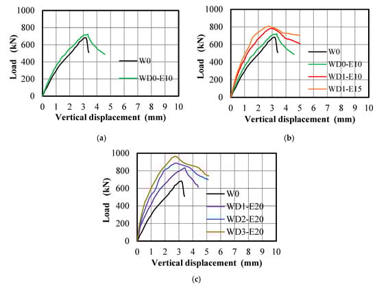
Figure 9.
Load–vertical displacement: (a) group G1, (b) group G2, and (c) group G3.
The increase in ECC layer thickness and the number of WSM (as seen in group G3) significantly improved the crack resistance and load-bearing capacity of the walls. The incorporation of ECC layers and welded steel meshes significantly enhanced the load-bearing capacity of walls. For group G3 specimens, especially those with several mesh layers (i.e., WD2-E20 and WD3-E20), displayed improved resistance to crack propagation and delayed failure. Moreover, the crack propagation was minimal, especially in specimens with more than one layer of reinforcement.
3.2. Load–Vertical Displacement Relationship and Dissipated Energy
In the given Figure 9a–c the load–vertical displacement for the three groups (G1, G2, and G3) of wall specimens was compared. Table 4 provides the ultimate displacement value (Δu) measured at the ultimate load value in addition to the absorbed energy (E) for all walls. The absorbed energy is calculated as the area under the load–displacement curves up to the maximum load [39]. Each group represents different experimental configurations, including varying ECC layer thickness and the inclusion of welded steel meshes.
Table 4.
Summary of the results of the tested walls.
The first group G1 acted as the control comparison, W0 had the lowest load-bearing capacity. However, wall WD0-E10, with a 10 mm non-reinforced ECC layer, improved performance over W0 by about 60%. The non-reinforced ECC layer increased both the peak load and the absorbed energy, as manifested by the higher stiffness and the area under the load–displacement curve shown in Figure 9a. Moreover, W0 showed earlier failure with a lower displacement value, while WD0-E10 reached higher displacement before failure, reflecting the benefits of the ECC layer in enhancing ductility.
The second group G2 which investigated the effect of the ECC layer reinforced with/without one layer of WSM exhibited load–displacement can be seen in Figure 9b. It can be reported that a thicker ECC layer (i.e., 15 mm in WD1-E15) upgraded both the load capacity and the absorbed energy compared to W0 and WD1-E10. Table 4 illustrated that WD1-E15 absorbed energy more than double that of wall W0, showing a significant enhancement due to a larger ECC layer. This resulted in higher ultimate capacity and greater ductility. The specimens with different ECC layers with one WSM presented much higher displacements before failure, indicating greater ductility compared to W0. In this context, increasing thickness from 10 mm (i.e., WD1-E10) to 15 mm (i.e., WD1-E15) further delayed the failure and upgraded both stiffness and energy absorption capacity. Comparing group G2 against G1 emphasized that both WD1-E10 and WD1-E15 behaved with superior performance compared to WD0-E10, as the ECC layer thickness increased, leading to greater energy absorption.
The third group G3 at which the RC walls were strengthened with 20 mm thickness of ECC reinforced with various WSM presented a load–displacement response depicted in Figure 9c. This group reflected further enhancement in structural performance. Table 4 shows that WD3-E20 (with three meshes) absorbed the highest energy gaining the largest ultimate capacity among all groups. Also, walls WD1-E20 and WD2-E20 (with one and two meshes, respectively) qualified this group to be outperformed compared to the others. The addition of steel meshes increased stiffness and energy absorption significantly due to the combined effect of the ECC layer in conjunction with the WSM. The vertical displacement at failure decreased slightly with increasing mesh count, as the additional reinforcement increased stiffness, thus limiting deformation. However, the overall displacement remained high compared to W0 due to the ECC layer’s inherent ductility.
Briefly, the comparison between the three groups revealed that specimens of G3 outperformed all counterparts of G1 and G2 in terms of both absorbed energy and load-bearing capacity, proving that the combined use of ECC and welded meshes was highly effective. Increasing the number of WSM led to better performance since the three layers of WSM could significantly enhance the energy consumed by about 2.75 times.
3.3. Ultimate Capacity
Table 4 summarizes the ultimate load (Pu) observed experimentally from all tested walls. For the master group G1, wall W0, which served as the benchmark wall for comparison, presented an ultimate load of 683 kN. However, the use of a non-reinforced 10 mm ECC layer as experimented in wall WD0-E10 grew Pu by approximately 8%. This may demonstrate that even a basic 10 mm ECC layer without any mesh reinforcement augmented the wall’s load-bearing capacity due to the improved ductility and strain-hardening behavior of ECC materials. The structural benefits of ECC are more related to crack resistance, energy absorption, and ductility; however, a significant increase in load capacity can be obtained with the presence of WSM.
The impact of different ECC layer thicknesses with the introduction of one WSM on the ultimate capacity has been studied in the second group, G2. Table 4 emphasized that employing 10 mm or 15 mm thicknesses of ECC layer reinforced one WSM could increase the NC wall by about 15% to 18%. This reveals that the introduction of a mesh augments the composite action, as the mesh helps to distribute the load more evenly, increases the stiffness, and delays the onset of cracking. This highlighted the combined effect of ECC reinforced with welded steel mesh. While increasing the ECC thickness enhances the wall’s ability to resist loads, the addition of WSM has a more significant impact. Therefore, the combination of ECC with one welded mesh provides a structural system with improved toughness and load-bearing capacity.
The third group used a 20 mm ECC layer reinforced with different numbers of welded steel meshes (one, two, and three meshes, for WD1-E20, WD2-E20, and WD3-E20). The thicker 20 mm ECC layer combined with mesh reinforcement has a significant positive contribution to Pu. The performance of G3 clearly emphasized that the number of WSM significantly impacted the behavior of the strengthened RC walls. As the number of meshes increased, the ultimate load capacity increased. The specimens with one or two meshes (i.e., WD1-E20 and WD2-E20, respectively) already showed a 22% and 30% increase in Pu compared to the baseline wall W0 as shown in Table 4. However, the ECC layer with 20 mm thickness reinforced with three WSM presented the highest Pu achieved by WD3-E20 recording about a 41% increase over the non-strengthened wall W0. This group confirmed that combining a thicker ECC layer with multiple meshes gained a synergistic reflection allowing the RC walls to carry higher loads before reaching Pu.
It should be noted that while the application of ECC layers increases the thickness of the specimens, the enhancement in compressive capacity cannot be attributed solely to the increase in cross-sectional area. This is because the strain-hardening behavior of ECC and the presence of embedded steel mesh delay crack localization, limits lateral dilation, and promotes a more uniform stress distribution across the section, which lead to an increase in both ultimate load and average compressive stress.
To further investigate the effects of the increase in the specimen’s thickness due to the application of the ECC layer, Table 4 shows the calculated average compressive stress achieved by the specimen at the ultimate load. It is seen that the control specimen exhibited a higher average compressive stress at the ultimate load when failure occurred compared to the strengthened specimens. This exhibited the brittle behavior of the unstrengthened concrete of the control specimen, where failure occurred after rapid stress localization On the other hand, the strengthened walls had enlarged cross-sections than the control wall and exhibited improved confinement due to the ECC layer and embedded mesh, resulting in more distributed stress transfer and delayed damage localization which resulted in the failure occurred at a lower average compressive stress but at a significantly higher total load, reflecting a transition from brittle to more ductile failure mode.
4. Numerical Analysis
The experimented walls were modeled numerically using the ABAQUS software program Abaqus 14 [40]. To ensure the credibility of finite element models (FEMs), the numerical results were validated against the experimental counterparts.
4.1. Constitutive Laws of Concrete and Steel
The Concrete Damage Plasticity (CDP) model was applied to characterize both NC and ECC materials, incorporating isotropic damage, tensile plasticity, and isotropic compression, which simulate the nonlinear performance of concrete in both tension and compression [7,41,42].
The stress–strain curves used for modeling NC and ECC concrete are illustrated in Figure 3 [43,44]. The measured stress–strain curves of steel elements were simplified for numerical modeling, as shown in Figure 3d. Several finite element method (FEM) simulations were conducted with varying sensitive parameters to determine the most suitable values.
For FEM calibration, numerous trials were conducted to determine the appropriate values for the CDP model’s sensitive parameters, including the ratio of biaxial to uniaxial compressive strengths (fbo/fco), dilation angle (ψ), the ratio of tensile stress to the compressive meridian (Kc), eccentricity (e), and the viscosity parameter (μ). The CDP parameters for NC were as follows: 1.16, 29°, 0.67, 0.10, and 0.00, respectively, which closely aligned with previous studies [21,45]. For ECC, the parameters were largely similar to NC, except for the dilation angle and viscosity, which were about 34° and 0.000001, respectively, consistent with previous research [27,46].
4.2. Setting Up Model
All concrete parts and the supports were modeled using an eight-node element (C3D8R) as shown in Figure 10, whereas the steel bars were modeled using a two-node and linear truss element (T3D2), as shown in Figure 10. However, the 90° bent bar anchors were introduced as solid parts using the C3D8R element type.
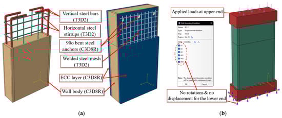
Figure 10.
Finite element model: (a) modeling for all parts and (b) loading and boundary conditions.
The interaction of steel reinforcements and the NC was the designed embedded element mechanism available in Abaqus, which allows a full bond between them in which the steel reinforcements were selected as the embedded truss elements inside the NC wall acted as the host region.
The ECC–NC interface surface was defined through two procedures. The first was surface-to-surface contact assumed to define the ECC–NC interface surface with a small differential friction coefficient of 0.3 employed in the tangential directions to display the de-bonding [47]. This mechanism was achieved by selecting the wall’s surface as the master surface, while the ECC strengthening surface was the slave rival. The second procedure was to employ the embedded anchors to bond the two surfaces. The constructed model rested on a thick steel plate with larger stiffness that acted as supporting plates on the upper and lower surfaces, simulating fixed boundary conditions at the bottom surface as shown in Figure 10b. Lastly, based on the sensitivity analysis, the size of the mesh was selected as 9 mm.
4.3. Verifications of FEM
The accuracy of the developed FEMs is compared with experimental results for validation purposes. The comparison was made in terms of comparing the numerically visualized crack patterns with the experimental results shown in Figure 11, the load–displacement responses illustrated in Figure 12, and the ultimate loads are summarized in Table 5.
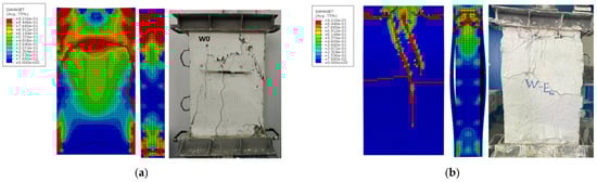
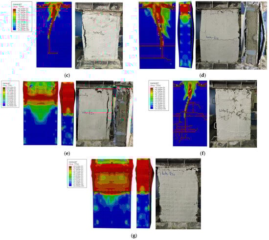
Figure 11.
Comparisons of the test and numerical results: (a) W0, (b) WD0-E10, (c) WD1-E10, (d) WD1-E15, (e) WD1-E20, (f) WD2-E20, (g) Wd3-E20.
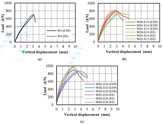
Figure 12.
Experimental and numerical load–displacement relationships for all tested walls: (a) group G1, (b) group G2, and (c) group G3.
Table 5.
Comparison between test and FEM prediction.
The average ratio between the FEM and test results was approximately 0.97 for the cracking stage and 0.98 for the ultimate stage, with corresponding coefficients of variation (CoV) of 0.001 and 0.001, respectively. Consistent with experimental observations, the numerical models successfully predicted sudden splitting cracks as the primary cause of wall failure, as demonstrated by models WD0-E10 and WD1-E10 (Figure 11b,c). Additionally, unexpected de-bonding of the ECC strengthening layer was observed in wall WD1-E-15, following the appearance of a sudden brittle crack with horizontal localization as shown with red color in Figure 11d. In a similar context, model WD2-E20 exhibited a pattern of closely spaced random cracks, reflecting the crack-tightening characteristics of ECC, as shown in Figure 11f. Moreover, the significance of a 20 mm thick ECC layer reinforced with three WSM was demonstrated in model WD3-E-20, as shown in Figure 11g. Excessive stresses were concentrated at the upper mid-height of the wall. This led to the deterioration of the ECC strengthening layer, indicating its capacity to bear higher loads.
These findings suggest that the developed models accurately simulate the experimental failure modes of the tested walls under vertical static monotonic loading. Figure 12 provides a comparison of the load–displacement responses for all the tested walls, showing that the FEMs closely align with the experimental outcomes.
5. Parametric Study
The validated FEM has been extended to better understand the reinforced NC wall strengthened with various configurations of ECC layers. It is noted that the configurations of anchor bolt incorporated here are different from those tested specimens. During the test, anchor bolts were selected based on constructability for the sample size to ensure adequate bonding between the ECC/UHPECC ferrocement layer and the concrete. However, in the parametric study, it aimed to evaluate the effect of the various configurations of ECC layers with various anchor distributions. Thus, the influence of anchorage parameters can be observed in a more generalized manner, allowing systematic variation in bolt number and distribution beyond the constraints of the experimental setup. The parametric study focuses on three techniques and three variables, including the strengthening configuration, number and configuration of anchors, and the ECC strengthening layer thickness with one WSM. The studied thickness varied between 8 mm, 12 mm, and 16 mm, giving strengthening thickness of (0.1 tw, 0.15 tw, and 0.2 tw, respectively). Figure 13 shows the schematic details of the parametric study for the three groups. The first group applied reinforced ECC jacket strips of the mentioned thicknesses, anchored to the NC wall as shown in Figure 13a. The second group applied a full ECC jacket with the same thicknesses, secured by anchors placed along the outer surface’s perimeter, including shorter sides (Figure 13b). The third group used a full ECC jacket along the outer surface’s perimeter, including shorter sides of the same thicknesses, bonded to the wall’s surface with evenly distributed anchors across the entire surface, as shown in Figure 13c. It should be noted that the ECC layer was applied on the shorter sides to provide continuous confinement and encircling of the wall cross-section.
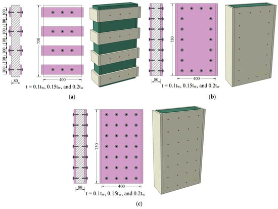
Figure 13.
Walls in parametric study analysis; (a) partial strengthening with anchors, (b) full strengthening with outer anchors, and (c) full-strengthening-full-surface anchors distribution.
Conversely, the objective of the parametric study was to investigate the influence of anchorage parameters in a more generalized manner, allowing systematic variation in bolt number and distribution beyond the constraints of the experimental setup.
Figure 14 shows the numerical cracking and failure patterns for RC walls under different strengthening techniques and thicknesses. The partial strengthening technique managed to contain crack propagation, though some splitting cracks remained, as illustrated by vertical red lines in Figure 14a. The full-strengthening technique with outer anchors, shown in Figure 14b, controlled excessive stress by distributing it throughout the strengthened RC wall. Stress concentration and damage were observed in the middle and upper zones, though less severe than with partial rivals. Increasing the thickness improved stress distribution, but concentrated damage still appeared in the upper-third zone. The full-strengthening technique with surface-wide anchoring, shown in Figure 14c, further reduced damage intensity compared to outer anchoring, as expected. Surface-wide anchoring ensured more even stress distribution, resulting in minimal damage areas, better load distribution, and superior performance compared to other configurations. The combination of a thicker ECC layer (0.20 tw) and full surface anchoring delivered the best performance overall, delaying the collapse stage. Furthermore, the results show that variations in anchor configuration mainly affected local stress transfer and interface behavior, with limited influence on the global torsional response.
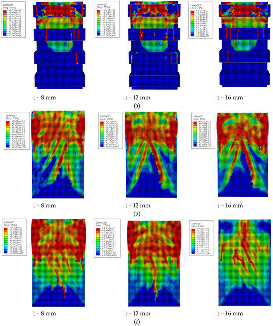
Figure 14.
Numerical failure patterns for walls in the parametric study: (a) walls with partial strengthening with anchors, (b) walls with full strengthening with outer anchors, (c) walls with full strengthening and full surface anchors.
Figure 15 summarizes the effect of strengthening methods studied in parametric study on the ultimate capacity. As seen in Figure 15, the ultimate load capacity increased as the ECC layer thickness grew from strengthening cross-sectional area from 0.1 tw to 0.2 tw. The improvement ranged from 5% to 28% for a thickness of 0.1 tw and from 13% to 50% for a thickness of 0.1 tw. This indicated that thicker ECC layers not only bear more load but also show a greater improvement in performance. The partial strengthening technique produced only a modest improvement of about 5–13%, likely due to the incomplete coverage of the strengthened area. This may suggest that while strengthening localized areas with anchors can improve performance, it is not optimal for significantly increasing load-bearing capacity. The second technique improved the ultimate capacity of the NC wall by about 21–32%, showing a notable improvement in loading capacity. Anchors placed around the outer perimeter provided more uniform distribution, enhancing structural integrity compared to the previous method. The full-area-full-anchors distribution increased the ultimate capacity by up to 50%, making it the most effective strengthening method. In this context, the effect of anchors distributed across the entire surface contributed significantly to improving the wall’s load-bearing capacity transferring the applied load into the whole strengthening parts.
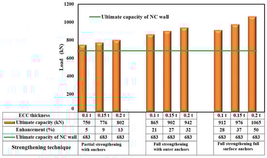
Figure 15.
Ultimate capacities for all walls modeled in the parametric study.
6. Conclusions
This study explores experimentally and numerically the performance of RC walls strengthened with ECC reinforced with/without WSM. The studied variables were: ECC layer thickness, and the number of WSM. Numerical models were also developed by using ABAQUS and their predictions were compared against the test results to validate their accuracy. A parametric study has been extended to investigate the influence of anchor placement, ECC layer thickness, and configuration on structural performance. The following observations and conclusions are drawn from this study:
- The experimental results of the proposed strengthening method demonstrated a better contribution to the ultimate capacity compared to the non-confined (NC) walls. The effect of ECC thickness combined with a number of WSM appeared with a significant effect on the ultimate capacity since increasing ECC thickness from 10 mm to 20 mm could upgrade the ultimate load from 8% to 18%. However, a more considerable contribution was gained with the use of an ECC layer with a thickness of 20 mm reinforced with three layers of WSM recording an increase of 41% in ultimate load.
- Test results show that the application of multiple layers of steel mesh embedded in ECC is effective. However, in real application, sufficient ECC thickness needs to be provided to ensure proper mesh embedment, adequate concrete cover, and reliable bond between layers. Thus, in practice, attention should be provided on both ECC thickness and mesh configuration for constructability and interface performance.
- The incorporation of thicker ECC layers and WSM significantly increased absorbed energy. Specifically, walls with thicker ECC layers and multiple WSM (such as WD3-E20) displayed superior performance, absorbing the highest energy about 2.7 times. The addition of welded steel meshes improved both stiffness and ductility, as demonstrated by the higher ultimate displacements before failure.
- The predictions made by the FEMs closely align with the corresponding test results, with an average prediction ratio calculated as 0.97 for the ultimate stage and 0.98 for its corresponding deflection.
- The parametric study demonstrates that the effectiveness of the ECC-based strengthening system is closely related to its proportion relative to the thickness of the original specimen. Increasing the ECC thickness resulted in enhanced torsional capacity, stiffness, and ductility of RC walls. Among the techniques, the full area strengthening method with full anchoring configuration proved to be the most effective, as it ensured uniform stress distribution and minimized damage, offering superior structural integrity compared to partial strengthening or outer-perimeter anchoring.
Author Contributions
Conceptualization, A.H.; Methodology, A.H. and M.G.; Software, A.H.; Validation, A.H. and M.G.; Formal analysis, A.H. and M.G.; Investigation, A.H. and M.G.; Data curation, A.H., M.A., M.G. and A.A.A.; Writing—original draft, A.H., M.G. and M.A.; Writing—review and editing, A.A.A. and S.F.; Visualization, A.H., M.G., M.A. and A.A.A.; Funding, A.H. and A.A.A.; Project administration, A.H. and A.A.A. All authors have read and agreed to the published version of the manuscript.
Funding
The authors wish to express their sincere gratitude to the first author for personally funding this research project. The Ongoing Research Funding Program (ORF-2026-343) supported by King Saud University, Riyadh, Saudi Arabia, is acknowledged.
Data Availability Statement
The original contributions presented in the study are included in the article, further inquiries can be directed to the corresponding author.
Acknowledgments
The authors extend their deep appreciation to the laboratory technicians at Kafrelsheikh University for their invaluable assistance during the testing phase. During the preparation of this work the authors used ChatGPT-5.2 in order to improve language and readability. After using this tool, the authors reviewed and edited the content as needed and take full responsibility for the content of the publication.
Conflicts of Interest
The authors declare no conflicts of interest.
References
- Jin, L.; Zhang, B.; Chen, F.; Miao, L.; Du, X. Experimental investigation on the size-dependent CFRP shear contribution in CFRP-strengthened RC shear wall. Eng. Struct. 2024, 307, 117800. [Google Scholar] [CrossRef]
- Jin, L.; Zhang, B.; Chen, F.; Du, X. CFRP-strengthened shear walls: Combined effects of CFRP and reinforcement ratio. Int. J. Mech. Sci. 2024, 282, 109634. [Google Scholar] [CrossRef]
- Al-Salloum, Y.; Abbas, H.; Elsanadedy, H.; Siddiqui, N.; Almusallam, T. Compression behavior of RC wall-like columns strengthened using NSM/CFRP system without shape modification. Structures 2023, 57, 105158. [Google Scholar] [CrossRef]
- Alsayed, S.; Almusallam, T.; Ibrahim, S.; Al-Hazmi, N.; Al-Salloum, Y.; Abbas, H. Experimental and numerical investigation for compression response of CFRP strengthened shape modified wall-like RC column. Constr. Build. Mater. 2014, 63, 72–80. [Google Scholar] [CrossRef]
- Liu, M.; Yuan, G.; Shu, Q.; Zhang, Y.; Lu, L. Experimental and numerical investigation on the seismic behaviors of RC shear walls with multiple post-openings before and after strengthening by steel plates. Eng. Struct. 2023, 279, 115552. [Google Scholar] [CrossRef]
- Sakr, M.A.; El-khoriby, S.R.; Khalifa, T.M.; Nagib, M.T. Modeling of RC shear walls strengthened with ultra-high performance fiber reinforced concrete (UHPFRC) jackets. Eng. Struct. 2019, 200, 109696. [Google Scholar] [CrossRef]
- Hamoda, A.; Emara, M.; Abadel, A.A.; Sennah, K. Influence of shear strengthening of reinforced normal concrete beams incorporating sustainable materials. Struct. Concr. 2024, 25, 2714–2731. [Google Scholar] [CrossRef]
- Hamoda, A.; Shahin, R.I.; Ahmed, M.; Abadel, A.A.; Baktheer, A.; Yehia, S.A. Strengthening of reinforced concrete columns incorporating different configurations of stainless-steel plates. Structures 2024, 64, 106577. [Google Scholar] [CrossRef]
- Hamoda, A.A.; Eltaly, B.A.; Ghalla, M.; Liang, Q.Q. Behavior of reinforced concrete ring beams strengthened with sustainable materials. Eng. Struct. 2023, 290, 116374. [Google Scholar] [CrossRef]
- Altin, S.; Anil, Ö.; Kopraman, Y.; Kara, M.E. Hysteretic behavior of RC shear walls strengthened with CFRP strips. Compos. B Eng. 2013, 44, 321–329. [Google Scholar] [CrossRef]
- Aslani, K.; Kohnehpooshi, O. Structural behavior of FRP-strengthened reinforced concrete shear walls with openings using finite element method. Adv. Struct. Eng. 2018, 21, 1072–1087. [Google Scholar] [CrossRef]
- Hernoune, H.; Benabed, B.; Kanellopoulos, A.; Al-Zuhairi, A.H.; Guettala, A. Experimental and numerical study of behaviour of reinforced masonry walls with NSM CFRP strips subjected to combined loads. Buildings 2020, 10, 103. [Google Scholar] [CrossRef]
- Konthesingha, K.; Masia, M.; Petersen, R.; Page, A. Experimental evaluation of static cyclic in-plane shear behavior of unreinforced masonry walls strengthened with NSM FRP strips. J. Compos. Constr. 2015, 19, 04014055. [Google Scholar] [CrossRef]
- Lima, M.; Doh, J.-H.; Fragomeni, S. New design chart for CFRP strengthened RC walls with opening in one-way action. Structures 2020, 24, 253–265. [Google Scholar] [CrossRef]
- Lima, M.M.; Doh, J.-H.; Hadi, M.N. Experimental study on RC walls with opening strengthened by externally bonded CFRP. J. Compos. Constr. 2019, 23, 04019008. [Google Scholar] [CrossRef]
- Lima, M.M.; Doh, J.-H.; Miller, D. Experimental study of RC walls with opening strengthened by CFRP. In Proceedings of the 23rd Australasian Conference on the Mechanics of Structures and Materials, Byron Bay, Australia, 9–12 December 2014; pp. 421–426. [Google Scholar]
- Prota, A.; Manfredi, G.; Cosenza, E. Ultimate behavior of axially loaded RC wall-like columns confined with GFRP. Compos. B Eng. 2006, 37, 670–678. [Google Scholar] [CrossRef]
- Wang, S.; Zhu, Q.; Zhao, J.-H.; Zhang, D.-F.; Feng, Z.-D.; Hu, J.-Y. Performance of multi-ribbed composite wall incorporating reactive powder concrete-filled steel tubular columns under axial compression. Structures 2024, 64, 106528. [Google Scholar] [CrossRef]
- Bastami, M.; Salehi, M.; Ghorbani, M.; Moghadam, A.S. Performance of special RC shear walls under lateral cyclic and axial loads. Eng. Struct. 2023, 295, 116813. [Google Scholar] [CrossRef]
- Ghalla, M.; Bahrami, A.; Badawi, M.; Mlybari, E.A. Novel sustainable techniques for enhancing shear strength of RC beams mitigating construction failure risk. Ain Shams Eng. J. 2024, 15, 103017. [Google Scholar] [CrossRef]
- Hamoda, A.A.; Ahmed, M.; Abadel, A.A.; Ghalla, M.; Patel, V.I.; Liang, Q.Q. Experimental and numerical studies of circular precast concrete slender columns with intermediate connection filled with high-performance concrete. Structures 2023, 57, 105204. [Google Scholar] [CrossRef]
- Emara, M.; Ghalla, M.; Hu, J.W.; Badawi, M.; Mlybari, E.A.; Ahmed, S.O. Enhancement of cantilevered RC beams exhibiting inadequate lap spliced reinforcement using sustainable reinforced ECC layers. Constr. Build. Mater. 2024, 428, 136272. [Google Scholar] [CrossRef]
- Cai, J.; Pan, J.; Xu, L.; Li, G.; Ma, T. Mechanical behavior of RC and ECC/RC composite frames under reversed cyclic loading. J. Build. Eng. 2021, 35, 102036. [Google Scholar] [CrossRef]
- Hamoda, A.; Emara, M.; Ahmed, M.; Abadel, A.A.; Patel, V.I. Flexural Behavior of Precast Rectangular Reinforced Concrete Beams with Intermediate Connection Filled with High-Performance Concrete. Buildings 2024, 14, 2823. [Google Scholar] [CrossRef]
- Li, T.; Deng, M.; Ma, Y.; Zhang, Y. In-plane behavior of URM wall with openings strengthened with ECC subjected to cyclic load. Structures 2021, 34, 2765–2776. [Google Scholar] [CrossRef]
- Dong, J.; Zheng, S.; Zhang, Z.; Liu, H.; Li, Y. Experimental study on seismic performance of RC beam-CFST column joint combination using ECC. Eng. Struct. 2024, 312, 118188. [Google Scholar] [CrossRef]
- Hamoda, A.; Shahin, R.; Ahmed, M.; Abadel, A.; Yehia, S. Flexural behavior of normal concrete circular beams strengthened with ECC and stainless steel tube. Mag. Concr. Res. 2024, 77, 171–188. [Google Scholar] [CrossRef]
- Hamoda, A.; Ghalla, M.; Yehia, S.A.; Ahmed, M.; Abadel, A.A.; Baktheer, A.; Shahin, R.I. Experimental and numerical investigations of the shear performance of reinforced concrete deep beams strengthened with hybrid SHCC-mesh. Case Stud. Constr. Mater. 2024, 21, e03495. [Google Scholar] [CrossRef]
- Hossain, K.; Yeganeh, A. Reinforced ECC-UHPC-SCC composite modular framed shear wall systems under lateral cyclic loading. Structures 2024, 63, 106350. [Google Scholar] [CrossRef]
- Ding, M.; Xu, W.; Wang, J.; Chen, Y.; Zhou, D.; Hou, L.; Sun, Y. Experimental and numerical investigation on axial compression behaviour of prefabricated ECC shell–reinforced concrete column. Case Stud. Constr. Mater. 2024, 21, e03562. [Google Scholar] [CrossRef]
- Zeng, J.-J.; Liang, Q.-J.; Cai, W.-J.; Liao, J.; Zhou, J.-K.; Zhu, J.-Y.; Zhang, L. Strengthening RC square columns with UHP-ECC section curvilinearization and FRP confinement: Concept and axial compression tests. Eng. Struct. 2023, 280, 115666. [Google Scholar] [CrossRef]
- Cui, T.; He, H.; Cheng, S. Seismic performance research on precast wall-beam out-of-plane joint with ECC post-cast zone. Eng. Struct. 2022, 266, 114488. [Google Scholar] [CrossRef]
- Ding, M.; Xu, W.; Wang, J.; Chen, Y.; Fang, R. Analytical study on seismic performance of ECC shell-RC column and its plastic hinge forming mechanism. Structures 2023, 58, 105489. [Google Scholar] [CrossRef]
- Hu, X.-W.; Ding, R.; Zhang, Z.-Y.; Fan, J.-S. Numerical study on optimized application of engineered cementitious composites in RC coupled shear wall structures. J. Build. Eng. 2024, 86, 108869. [Google Scholar] [CrossRef]
- Erfan, A.M.; Abd Elnaby, R.M.; Elhawary, A.; El-Sayed, T.A. Improving the compressive behavior of RC walls reinforced with ferrocement composites under centric and eccentric loading. Case Stud. Constr. Mater. 2021, 14, e00541. [Google Scholar] [CrossRef]
- Hamoda, A.; Shahin, R.; Abadel, A.A.; Sennah, K.; Ahmed, M.; Yehia, S.A. Shear strengthening of normal concrete deep beams with openings using strain-hardening cementitious composites with glass fiber mesh. Structures 2024, 71, 107994. [Google Scholar] [CrossRef]
- Hamoda, A.; Abadel, A.A.; Ahmed, M.; Wang, V.; Vrcelj, Z.; Liang, Q.Q. Punching shear performance of reinforced concrete slab-to-steel column connections incorporating ECC and UHPECC. Eng. Struct. 2025, 322, 119145. [Google Scholar] [CrossRef]
- ASTM C39/C39M; Standard Test Method for Compressive Strength of Cylindrical Concrete Specimens. ASTM International: West Conshohocken, PA, USA, 2021.
- Hamoda, A.; Ahmed, M.; Abadel, A.A.; Alghamdi, H.; Baktheer, A.; Attia, M.M.; Emara, M. Experimental investigations and design of precast concrete-filled steel corrugated sheet slender columns with intermediate connection. Struct. Concr. 2025, 27, 193–210. [Google Scholar] [CrossRef]
- Hibbitt, K.; Sorensen, I. ABAQUS Theory Manual, User Manual and Example Manual; Simulia: Providence, RI, USA, 2000. [Google Scholar]
- Hamoda, A.; Ahmed, M.; Ghalla, M.; Liang, Q.Q.; Abadel, A.A. Flexural performance of precast circular reinforced concrete members with intermediate connection filled with ultra-high-performance-concrete. Case Stud. Constr. Mater. 2023, 19, e02386. [Google Scholar] [CrossRef]
- Hamoda, A.; Ahmed, M.; Sennah, K. Experimental and numerical investigations of the effectiveness of engineered cementitious composites and stainless steel plates in shear strengthening of reinforced concrete beams. Struct. Concr. 2023, 24, 2778–2799. [Google Scholar] [CrossRef]
- Carreira, D.J.; Chu, K.H. Stress-strain relationship for plain concrete in compression. J. Am. Concr. Inst. 1985, 82, 797–804. [Google Scholar] [CrossRef]
- Ma, H.; Zhang, Z.; Ding, B.; Tu, X. Investigation on the adhesive characteristics of Engineered Cementitious Composites (ECC) to steel bridge deck. Constr. Build. Mater. 2018, 191, 679–691. [Google Scholar] [CrossRef]
- Hamoda, A.; Hossain, K. Numerical assessment of slab–column connection additionally reinforced with steel and CFRP bars. Arab. J. Sci. Eng. 2019, 44, 8181–8204. [Google Scholar] [CrossRef]
- Sennah, K.; Hamoda, A.; Abadel, A.; Yehia, S.; Shahin, R. Shear strengthening of simply-supported deep beams with openings incorporating combined steel-reinforced engineered cementitious composites and externally bonded carbon fibre-reinforced polymer sheets. Mag. Concr. Res. 2024, 77, 154–170. [Google Scholar] [CrossRef]
- Feng, J.; Fang, S.; Chen, M.; Fang, Z.; Liang, W. Effect of joint width on shear behaviour of wet joints using reactive powder concrete with confining stress. Eng. Struct. 2023, 293, 116566. [Google Scholar] [CrossRef]


Disclaimer/Publisher’s Note: The statements, opinions and data contained in all publications are solely those of the individual author(s) and contributor(s) and not of MDPI and/or the editor(s). MDPI and/or the editor(s) disclaim responsibility for any injury to people or property resulting from any ideas, methods, instructions or products referred to in the content. |
© 2026 by the authors. Licensee MDPI, Basel, Switzerland. This article is an open access article distributed under the terms and conditions of the Creative Commons Attribution (CC BY) license.