Abstract
Numerical simulation of the electrical conductivity of carbon fiber-reinforced asphalt concrete is essential for understanding its electrical behavior, yet research in this area remains limited. This study prepared six groups of Marshall specimens with carbon fiber (CF) contents of 0.1 wt%, 0.2 wt%, 0.3 wt%, 0.4 wt%, 0.5 wt%, and 0.6 wt%. The resistivity and asphalt concrete (AC) impedance spectra were measured to analyze the effect of fiber content on electrical performance. Nyquist diagrams were fitted to establish an equivalent circuit model, and a representative volume element (RVE) finite element model was developed. The Generalized Effective Medium (GEM) equation was employed to fit the resistivity data. The results show that the resistivity exhibits a two-stage characteristic—an abrupt decrease followed by stabilization, with an optimal CF content range of 0.2–0.4 wt%. Among the equivalent circuit parameters, the contact resistance (R1) and tunneling resistance (R2) significantly decreased, the growth of interface capacitance (C1) slowed, the constant phase element ZQ increased, and the non-monotonic change of volume resistance (R3) reflected the heterogeneity of the internal void distribution of the material. The finite element numerical solution for resistivity, derived from the GEM equation, aligns well with experimental values, validating the proposed simulation approach.
1. Introduction
Ice and snow accumulation on road surfaces can reduce the tire–pavement adhesion coefficient by over 75%, leading to at least a 10% increase in traffic accidents [1,2]. Conductive pavement technology has emerged as an effective active electro-thermal de-icing solution, with various forms including conductive cement concrete [3], conductive asphalt concrete pavement [4], conductive surface overlay [5], and embedded heating pipe systems [6]. Among these, conductive asphalt concrete offers superior driving comfort, ease of maintenance, uniform ice melting, excellent durability, and broad application prospects [7,8]. By incorporating conductive materials, it maintains original road performance while acquiring electro-thermal conversion capability through current-induced heating effects, significantly enhancing winter road travel safety [9,10,11].
Commonly employed conductive materials for pavements include graphite, steel fibers, graphene, and carbon fibers. Graphite tends to agglomerate in the asphalt matrix, resulting in unstable conductive networks [12,13]. Steel fibers exhibit excellent electrical and mechanical properties [14,15,16] but are susceptible to oxidation, which increases resistivity and degrades conductive performance over time [17]. While graphene possesses outstanding electrical characteristics, its high cost limits large-scale engineering applications [18,19]. In contrast, carbon fibers with a resistance value of approximately 10−3 Ω [20] offer the advantages of high strength, high modulus, low density, excellent conductivity, and good dispersion stability [21,22]. They also demonstrate remarkable chemical stability, are insoluble in water, exhibit low oxidation rates in natural environments, and maintain stable performance over extended periods. Moreover, carbon fibers show excellent compatibility with the asphalt concrete matrix, facilitating the formation of an ideal structural and electrical network [23,24]. Beyond significantly improving fatigue life and crack resistance of asphalt concrete [25,26], carbon fiber addition enhances conductive performance [27,28] and enables intelligent functionalities such as self-healing and self-heating [29,30].
Previous studies indicate that combining multiple conductive additives can synergistically enhance asphalt concrete performance. Huang et al. [31] employed graphene-carbon fiber composites, observing significant resistivity reduction alongside improved stability and maximum flexural strain. Wang et al. [32] achieved a volume resistivity of 4.1 Ω·m using 3 vol% carbon fibers (6 mm) and 15 vol% graphite, while maintaining crack resistance. Liu et al. [33] prepared conductive asphalt concrete with 0.3% carbon fibers (5 mm) and 40% graphene, reporting a decrease in resistivity ∞ to 835Ω, along with increase of 4%, 18%, and 78% in Marshall stability, splitting strength, and dynamic stability, respectively. Wang et al. [34] discovered that a conductive asphalt concrete with a carbon fiber mixture ratio of (3 mm:6 mm:9 mm = 2:6:2) exhibited higher piezoresistive response sensitivity and stress/strain sensitivity, with a resistivity of 35 Ω·m. Fu et al. [35] improved conductivity by incorporating 0.4% carbon fibers and 2% carbon powder, enhancing dynamic stability by 75.6%.
Despite the promising potential of carbon fiber-reinforced conductive asphalt concrete, research on its conductive mechanism faces several challenges. Existing studies indicate that the conductive network formed by carbon fibers is the key factor determining electrical performance [36,37]. However, the specific formation mechanism, key influencing factors, and quantitative relationship with macroscopic properties remain unclear. Current microstructural characterization techniques offer limited accuracy in revealing the true internal structure, while traditional experimental methods are time-consuming and cannot effectively capture dynamic microstructural changes during conduction [38]. Furthermore, most theoretical analyses rely on simplified models that ignore material heterogeneity, resulting in significant deviations between predictions and experimental data [39].
This study conducted systematic electrical resistivity and impedance spectroscopy tests to analyze the average resistivity and AC impedance spectra of carbon fiber-reinforced asphalt concrete. The influence of carbon fiber content on electrical properties was thoroughly investigated. Through equivalent circuit modeling, key parameters, including contact resistance, tunneling resistance, interfacial capacitance, volume resistance, and total impedance, are characterized to determine the optimal carbon fiber content. Furthermore, an RVE model of carbon fiber-reinforced asphalt concrete was developed using finite element software. Experimental resistivity values were fitted with the GEM equation, validating the reliability and accuracy of the proposed numerical model.
2. Test Materials and Specimen Preparation
2.1. Raw Materials
The base asphalt used was AH-70# road asphalt (Sinopec Qilu Petrochemical Company, Zibo, China), the physical properties of which are listed in Table 1. The asphalt concrete, incorporating 9 mm short-cut carbon fibers (Songhu Shenjian Technology Co., Ltd., Dongguan, China) as the conductive phase, was prepared using limestone aggregates (0–3, 3–5, 5–10, and 10–16 mm) (Gongyi Yuanheng Water Purification Material Factory., Zhengzhou, China) and limestone mineral powder (Gongyi Yuanheng Water Purification Material Factory, Zhengzhou, China). The relevant technical specifications are provided in Table 2. Copper foil tape (Suzhou Hengyun Packaging Materials Co., Ltd., Suzhou, China) serves as the electrode material due to its thin profile, adhesive backing, and excellent conductivity.

Table 1.
Asphalt binder properties.
Table 2.
Technical indexes of limestone aggregate.
2.2. Marshall Specimen Design and Preparation
The AC-13-graded asphalt concrete, due to its good smoothness, low cost and convenient construction, is widely used in the surface layers of various grades of roads [40,41]. The aggregate-to-binder ratio was 1.2, with the asphalt content standing at 5.19% of the aggregate weight.
Carbon fibers tend to agglomerate in asphalt concrete, worsening conductive properties. When CF content exceeds 0.3 wt% of the asphalt mixture mass, fiber dispersion uniformity declines, affecting conductive properties; beyond 0.6 wt%, low-temperature performance is significantly compromised [42]. Therefore, six CF contents—0.1 wt%, 0.2 wt%, 0.3 wt%, 0.4 wt%, 0.5 wt%, and 0.6 wt%—were selected. Here, CF-0.1% represents a specimen with a carbon fiber content of 0.1 wt%. A dry-mixing process with a total mixing time of 270 s was employed. Aggregates and carbon fibers were mixed for 90 s, followed by liquid asphalt (90 s) and, finally, limestone powder filler (90 s) [43]. The fabrication process is shown in Figure 1. In addition, the pavement performance of the mix proportion adopted in this study has been verified by other relevant tests conducted by the research group, and it has been confirmed to meet the specification requirements [40].
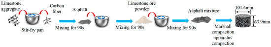
Figure 1.
Fabrication of Marshall specimens of carbon fiber asphalt concrete.
2.3. Test Method
2.3.1. Resistivity Test
The double-electrode method was employed at a 15 °C room temperature. Copper foil strips ensured electrical contact, and a VC8246A digital multimeter (Dongguan Shengli Testing Equipment Co., Ltd., Dongguan, China) measured resistances below 40 × 106 Ω. After measuring the resistance, the resistivity of the sample was obtained according to the second Ohm’s law in Equation (1):
where ρ is the resistivity (Ω·m), R is the measured resistance (Ω), L is the electrode distance (m), and S is the conductive area of the electrodes (m2).
2.3.2. Impedance Test
The ideal resistor follows Ohm’s law, maintaining a constant resistance value that is independent of frequency. However, the behavior of real-world circuit components is often complex. Therefore, this paper introduces the concept of impedance and constructs an equivalent circuit model, as shown in Figure 2. In the equivalent circuit model, elements such as resistance (R), capacitance (C), and constant-phase-angle components (Q/CPE) are commonly used to establish the model. Using the Zsimpwin (v3.6) software for spectral fitting, parameters such as the resistance, capacitance, characteristic frequency, and dispersion coefficient of the equivalent circuit can be extracted.
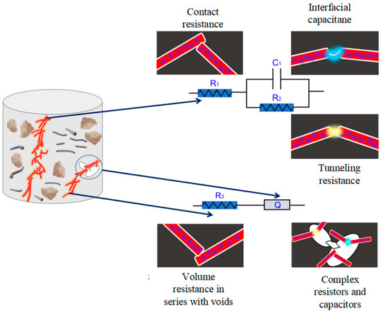
Figure 2.
Equivalent circuit model.
Due to the geometric structure of the conductive filler and the size and spatial distribution of the voids within the asphalt concrete, overlapping and misalignment of CF and CF clusters are prone to occur [44]. Therefore, in this study, a new equivalent circuit component model, R1(C1R2(QR3)), considering the void effect was constructed, as shown in Figure 3. The impedance formulas are as shown in Equations (2) and (3):
where ZQ denotes the equivalent resistance and capacitance (CPE, denoted by Q) induced by the complex void structure, j . ω = 2 πf is the angular frequency, and Y0 represents capacitance or resistance. When n = 1, Q characterizes ideal capacitance with C = Y0. When n = 0, Q characterizes ideal resistance with R = 1/Y0. When 0 < n < 1, Q exhibits resistive–capacitive coupling characteristics. R1 represents the contact resistance of carbon fiber, while R2 and C1 denote the breakdown resistance and interfacial capacitance of the carbon fiber/asphalt binder/carbon fiber structure, respectively. R3 represents the volume resistance in series with the void in the current direction; Z denotes the total impedance of the equivalent circuit.
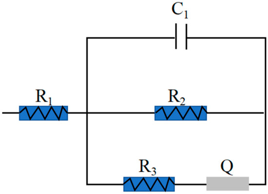
Figure 3.
New equivalent circuit diagram.
3. Test Results and Analysis
3.1. Asphalt Concrete Resistivity
The resistivity of asphalt concrete with different carbon fiber contents is shown in Figure 4. At 0.1 wt% CF content, resistivity was 171.56 Ω∙m, six orders of magnitude lower than ordinary asphalt concrete (107–109 Ω∙m) [45]. This reduction occurs because, at low fiber content values, fibers disperse as discrete clusters, hindering effective conductive path formation. At 0.2 wt%, resistivity dropped to 13.25 Ω∙m, representing a reduction of one order of magnitude, and at 0.3 wt%, the resistivity further dropped to 3.79 Ω∙m, though this decrease is less than one order of magnitude. The carbon fiber content of CF-0.3% approaches the percolation threshold, with conductive paths gradually increasing, marking the material transition from being an insulator to a conductor. When the carbon fiber content is 0.5 wt%, resistivity reaches a relatively low level of 3.19 Ω∙m, with a slight upward trend likely due to excessive fiber aggregation introducing internal defects. The optimal resistivity is achieved within 0.2 wt% to 0.4 wt%. Consequently, the CF-0.5% and CF-0.6% specimens were excluded from subsequent impedance tests.
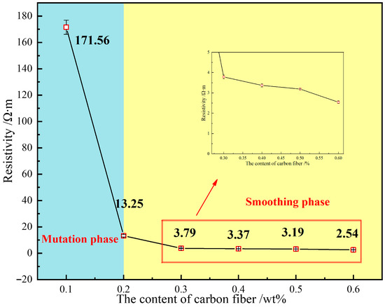
Figure 4.
Relationship between electrical resistance and carbon fiber content.
The comprehensive average resistivity curve reveals a two-stage process—an abrupt decrease followed by stabilization. In the abrupt decrease stage, a slight increase in carbon fiber content by 0.1 wt% leads to a dramatic reduction in resistivity. For example, the resistivity of CF-0.2% is only 7.72% of that of CF-0.1%. In the stabilization stage, CF influence diminishes considerably. At this stage, with CF values of 0.3 wt%, 0.4 wt%, 0.5 wt%, and 0.6 wt%, the resistance values are 2.21%, 1.96%, 1.86%, and 1.48% of that of CF-0.1%, respectively. Thus, the CF content increase enhances conductivity, exhibiting characteristic “abrupt decrease stabilization” behavior.
3.2. Analysis of AC Impedance Spectrum: Nyquist Diagram
Figure 5 presents Nyquist diagrams for different CF contents. As CF content increases from 0.1 wt% to 0.2 wt%, the impedance spectrum real part decreases by 1–2 orders of magnitude, and the capacitive arc significantly shrinks. Beyond 0.2 wt%, the resistivity change rate stabilizes, aligning with typical conductive asphalt concrete impedance response behavior.
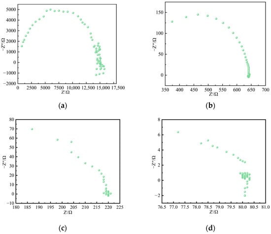
Figure 5.
Electrochemical impedance spectroscopy fitting curves for CF. (a) CF-0.1%; (b) CF-0.2%; (c) CF-0.3%; (d) CF-0.4%.
3.3. AC Impedance Spectrum Analysis: Equivalent Circuit Fitting
Figure 6 compares experimental AC impedance spectra with equivalent circuit-fitted values. At 0.1 wt% and 0.2 wt% CF content, the fitted curve in the high-frequency region lay above the measured data. This deviation can be attributed to inductive effects that reduced the fitting accuracy, leading to a mismatch between the simulated and experimental results in the Nyquist plot. As CF content increases, the deviation between the fitted values and the test values gradually decreased. This was because, at higher carbon fiber contents, the conductive grid was composed of fibers, and the carbon fibers provided a convenient path for charge migration, thereby improving the conductivity. The AC impedance spectrum test curves and fitted curves are smooth and match well with the proposed equivalent circuit model, with chi-square values below 1 × 10⁻³, confirming the model’s capability to describe carbon fiber asphalt concrete electrical properties.
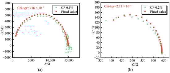
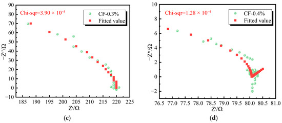
Figure 6.
Electrochemical impedance spectroscopy fitting curves for CF. (a) CF-0.1%; (b) CF-2%; (c) CF-3%; (d) CF-4%.
3.4. Reliability Analysis of Equivalent Circuit Models
Figure 7 illustrates the variations in electrical parameters derived from the equivalent circuit model R1(C1R2(QR3)). As CF content increases from 0.1 wt% to 0.4 wt%, contact resistance R1 decreases by 37.4%, 85.2%, and 90.0%, respectively. This reduction can be attributed to the increased spatial density of fibers within the asphalt matrix, which promotes the formation of a denser three-dimensional conductive network and enhances the probability of effective physical contact between fibers. When the carbon fiber content increases from 0.3 wt% to 0.4 wt%, the R1 decline becomes more moderate (from 85.2% to 90.0%), indicating that at 0.3 wt% CF content, the direct contact of fibers with the grid approaches saturation, and the marginal benefit of the new fibers for forming new contact points gradually decreases. The tunneling resistance R2 showed a more significant downward trend, decreasing by 97.6%, 99.1%, and 99.9%, respectively. At low CF content (0.1 wt%), large average fiber spacing and inter-fiber spacing result in high tunneling resistance and insulating behavior. As CF content increases, average fiber spacing decreases rapidly, exponentially increasing electron tunneling probability and drastically reducing R2 by orders of magnitude. Thus, R2 change is the core dominant factor governing the abrupt increase in composite conductivity near the percolation threshold. Additionally, resistance R3 shows a non-monotonic change of “decrease → increase → decrease”, since, during the heating or increase of the electric field process of asphalt concrete, it successively experiences an increase in ion mobility, resulting in a decrease in resistance, an increase in asphalt expansion, and a widening of the gap between conductive particles, thus increasing resistance and local carbonization or breakdown and forming new conductive channels—resulting in a decrease in resistance again, thereby causing the non-monotonic change of R3 [46]. Regarding the capacitance, C1, variation, in the 0.1–0.2 wt% range, C1 increases slightly due to large CF gaps and limited interface capacitors. At 0.2–0.3 wt% (seepage stage), the CF spacing decreases, promoting a significant increase in the number of interface capacitors, and the capacitance is connected in parallel to form more CF clusters, resulting in a significant increase in C1. At 0.3–0.4 wt%, the conductive network stabilizes, with excess capacitance converting to conductive pathways, causing C1 to decrease.
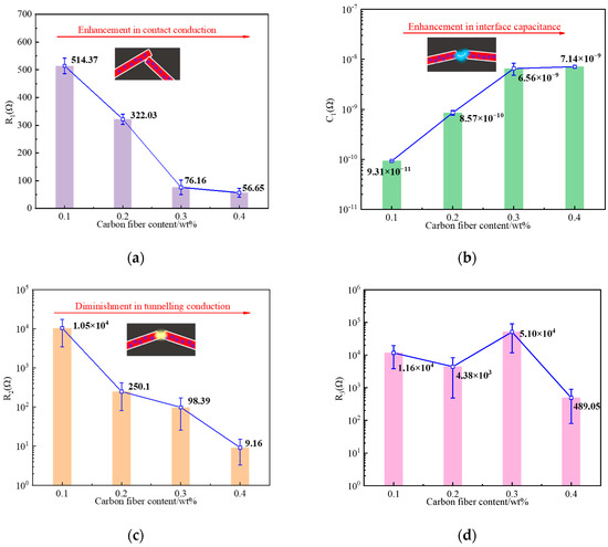
Figure 7.
R1 (C1R2 (QR3)) equivalent circuit model-fitting electrical parameter changes. (a) R1; (b) C1; (c) R2; (d) R3.
4. Numerical Simulation Analysis of Conductive Properties
4.1. Construction of the REV Model
Carbon fiber-reinforced conductive asphalt concrete is a multiphase composite material whose electrical conduction behavior is influenced by multiple factors, including inter-fiber contact resistance, interfacial tunneling and capacitive effects, pore series resistance, and morphology-dependent resistive–capacitive coupling. Based on resistivity and impedance test results, conductive performance is primarily governed by the percolation network formed through fiber contacts. Therefore, in constructing the three-dimensional microscale representative volume element (RVE) model, emphasis is placed on the percolation effect, while secondary factors, such as tunneling, capacitance, and polarization, are neglected. The following simplified assumptions are adopted [44,45]: (1) Fibers are randomly distributed in rigid contact. (2) Composite resonances and dielectric polarization are ignored, meaning we only consider resistive characteristics.
On the Digmat-FE platform (v2017), two different structures were used to establish RVE models for replacing carbon fiber asphalt concrete: one simulating carbon fibers as randomly embedded inclusions (length-to-diameter ratio = 40) [47], and the other simulating the asphalt mortar matrix (as shown in Figure 8).
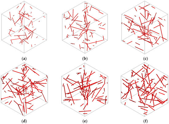
Figure 8.
The RVE geometric model of CF. (a) CF-0.1%; (b) CF-0.2%; (c) CF-0.3%; (d) CF-0.4%; (e) CF-0.5%; (f) CF-0.6%.
According to the RVE model, the electrical properties of carbon fiber asphalt concrete are analyzed using finite element analysis. Both carbon fiber and asphalt mortar matrix element types are tetrahedral current transmission elements (SOLID232) with 10 nodes, with each node having one voltage degree of freedom. It is assumed that the carbon fiber and the asphalt mortar matrix are isotropic materials, and only the resistive properties are considered. The resistivity of the carbon fiber is set at 1 × 10⁻⁵ Ω·m, and the resistivity of the asphalt mortar matrix is set at 1 × 10⁴ Ω·m [47,48].
4.2. Analysis of Current Density Contour Map
Figure 9 illustrates the current density distribution of carbon fibers along the voltage direction. As CF content increases from 0.1 wt% to 0.6 wt%, the current density distribution becomes progressively more uniform. The conductive network evolves from a sparse partial connection to a dense continuous structure, continuously enhancing electrical conductivity. In the low-content range (0.1–0.3 wt%), conductivity improvement is pronounced. Beyond 0.3 wt%, although conductivity continues to increase, the rate of improvement slows compared to that in the low-content stage. This indicates the existence of a critical range of carbon fiber content at which the efficiency of conductivity enhancement transitions from rapid to gradual.
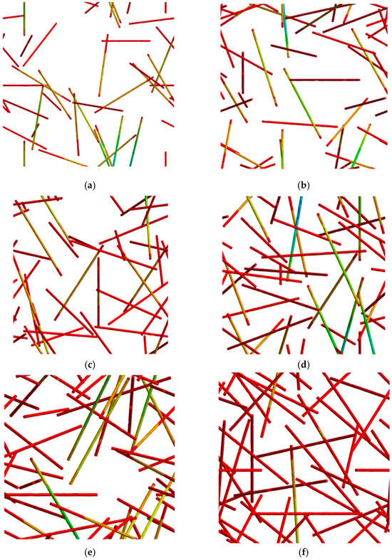
Figure 9.
Cloud map of the current density of CF. (a) CF-0.1%; (b) CF-0.2%; (c) CF-0.3%; (d) CF-0.4%; (e) CF-0.5%; (f) CF-0.6%.
4.3. Resistivity Analysis Based on the REV Model
When calculating the effective resistivity of conductive multiphase composites using the finite element analysis (FEA) method, the electrical loss P is first computed, from which the effective resistivity ρeff of the composite is derived. The corresponding expressions are given in Equations (4) and (5) [47,49]. To further determine the percolation threshold and elucidate the underlying conduction mechanism, an appropriate resistivity model must be selected to fit the FEA numerical results. This enables the derivation of a theoretical equation that describes the effective resistivity.
The GEM equation integrates effective medium theory and seepage theory. It can accurately describe the seepage behavior of composite materials and is widely used for fitting analysis of experimental data. Each parameter in this equation has a clear physical meaning, which is convenient for judging the rationality of the fitting results. The GEM resistivity calculation equation is shown in Equations (6) and (7) [49]. It is worth noting that the GEM equation belongs to a typical implicit function form, which cannot be explicitly expressed, and the setting of the initial value t in the fitting process is rather difficult. If the initial value is not selected properly, it is likely to cause the iterative process to fail to converge or the fitting error to be large. Compared with most current mathematical analysis software, 1Stopt (v1.5) does not require manual presetting of initial values. This software can automatically generate initial approximations and find the optimal solution based on the global optimization algorithm, thereby achieving better fitting results. Therefore, in this paper, the 1Stopt (v1.5) software is used to fit the experimental data with the GEM equation.
where U is applied voltage (V), L is the RVE model length along the loading direction (m), S is the loading area (m2), ρ1 is the resistivity of medium one (Ω·m), ρeff is the effective resistivity of the composite material (Ω·m), f1 is the volume fraction of medium one, and fc is the seepage threshold of the composite material.
Figure 10 compares the simulated and experimental resistivity values of asphalt concrete with varying carbon fiber contents. As shown, resistivity progressively decreases with increasing CF content, with reasonable agreement between simulated and experimental measurements. The GEM equation resistivity values are 272.36 Ω·m, 15.39 Ω·m, 3.56 Ω·m, 1.56 Ω·m, 1.26 Ω·m, and 1.01 Ω·m at 0.1 wt%, 0.2 wt%, 0.3 wt%, 0.4 wt%, 0.5 wt%, and 0.6 wt% CF content, respectively, with a fitted percolation threshold of 0.296 wt%. The experimental values are 171.56 Ω·m, 13.25 Ω·m, 3.79 Ω·m, 3.37 Ω·m, 3.19 Ω·m, and 2.54 Ω·m. Some deviations between experimental and simulated values are observed, which can be attributed to two main factors. First, for every 10-fold increase in the aspect ratio of carbon fibers, the number of unit cells required in the representative volume element (RVE) model increases by approximately 3000 times. Due to constraints in computational memory and time, the maximum aspect ratio in this simulation was limited to 40. Second, the model considers only the resistive properties of the carbon fibers and asphalt mortar matrix, without accounting for the influence of dielectric characteristics [47].
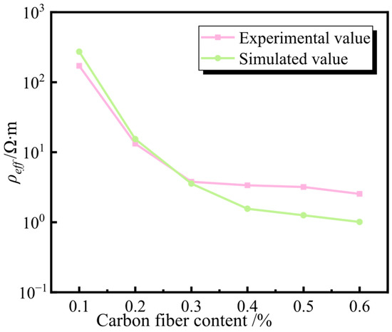
Figure 10.
Fitting curve of the GEM equation for CF.
5. Conclusions
This study employed carbon fibers as conductive fillers to develop modified asphalt concrete composites. Electrical properties were systematically examined through resistivity measurements and impedance spectroscopy. An RVE model numerically simulated conductive behavior, with simulation results compared and analyzed using experimental data. The key conclusions are as follows:
- (1)
- Carbon fiber incorporation significantly enhances asphalt concrete’s electrical conductivity. Resistivity exhibits “abrupt decline stabilization”, as well as a two-stage change, with the increase in the dosage. At 0.1 wt%, it was 171.56 Ω∙m, and it dropped sharply to 13.25 Ω∙m at 0.2 wt%. After exceeding 0.3 wt%, it tended to stabilize. At low dosages, the dispersion of the fibers was poor, and the conductive pathways were insufficient; at around 0.2 wt%, the percolation threshold was reached, and the tunneling effect dominated. After exceeding 0.3 wt%, the conductive network tended to perfect, but the fibers were prone to agglomeration, resulting in a slight increase in resistance. Overall, the optimal dosage range was 0.2–0.4 wt%.
- (2)
- Carbon fiber addition significantly modifies the conduction mechanism. As doping content increases from 0.1 wt% to 0.2 wt%, a pronounced percolation transition occurs with decrease in impedance real part of 1–2 orders of magnitude, indicating initial formation of a conductive network. Beyond 0.3 wt%, resistivity stabilizes, and the Nyquist plot evolves from single to double capacitive arcs, reflecting a conduction mechanism shift from interface polarization to Ohmic conduction. The established equivalent circuit model shows good agreement with experimental data. A slight deviation caused by inductive response is observed in the high-frequency region at low doping contents (0.1–0.2 wt%), while excellent fitting accuracy is achieved at higher doping levels. These results fully demonstrate that the model can accurately describe the electrical properties and their evolution in carbon fiber-reinforced asphalt concrete at different stages.
- (3)
- Based on impedance tests and microstructure characteristics, a new equivalent circuit model R1(C1R2(QR3)) characterizes the conductive mechanism. With increasing content, conductive behavior shows a two-stage evolution. At 0.1–0.2 wt%, the tunneling effect dominates and ZQ decreases, indicating that the capacitive behavior is approaching the ideal level; at 0.2–0.4 wt%, percolation gradually replaces tunneling, with continuous network formation and CF direct contact dominance. R1 and R2 significantly decrease, the C1 growth rate slows, and ZQ increases. R3 non-monotonic change reflects void distribution heterogeneity.
- (4)
- The resistivity values calculated based on the GEM equation are relatively close to the experimental values. Both show consistent trends with the variation in carbon fiber (CF) content. Additionally, the calculated flow threshold of 0.296 wt% is very close to the experimental flow threshold of 0.3 wt%, verifying the validity of this model. Simulation deviations mainly result from fiber aspect ratio limitations and dielectric property simplifications. This study provides a theoretical basis for conductive asphalt concrete ratio design and performance prediction.
Author Contributions
Y.Y.: Investigation, Software, Formal Analysis, Writing—Original Draft, Writing—Review and Editing. L.H.: Investigation, Software, Writing—Original Draft, Writing—Review and Editing. P.X.: Investigation, Writing—Review and Editing. B.L.: Conceptualization, Methodology, Supervision, Writing—Review and Editing. H.Z.: Supervision, Writing—Review and Editing. All authors have read and agreed to the published version of the manuscript.
Funding
The authors would like to acknowledge the support received from the National Natural Science Foundation of China (52268043).
Data Availability Statement
The original contributions presented in this study are included in the article. Further inquiries can be directed to the corresponding authors.
Conflicts of Interest
The authors declare no conflict of interest.
References
- Yehia, S.; Tuan, C.Y.; Ferdon, D.; Chen, D. Conductive concrete overlay for bridge deck deicing: Mixture proportioning, optimization, and properties. Aci Mater. J. 2000, 97, 172–181. [Google Scholar]
- Zhao, X.J.; Zhao, Y.M.; Zheng, M.L. Enhancing the efficiency of ice-resistant materials in asphalt road Surfaces: A comprehensive performance analysis. Coatings 2024, 141, 14010037. [Google Scholar] [CrossRef]
- Lu, D.; Leng, Z.; Lu, G.Y.; Wang, D.Y.; Huo, Y.L. A critical review of carbon materials engineered electrically conductive cement concrete and its potential applications. Int. J. Smart Nano Mater. 2023, 14, 189–215. [Google Scholar] [CrossRef]
- Lu, D.; Jiang, X.; Leng, Z.; Huo, Y.; Wang, D.; Zhong, J. Electrically conductive asphalt concrete for smart and sustainable pavement construction: A review. Constr. Build. Mater. 2023, 406, 133433. [Google Scholar] [CrossRef]
- Wang, T.; Fassbender, S.; Dong, W.; Schulze, C.; Oeser, M.; Liu, P. Sensitive surface layer: A review on conductive and piezoresistive pavement materials with carbon-based additives. Constr. Build. Mater. 2023, 387, 131611. [Google Scholar] [CrossRef]
- Liu, K.; Fu, C.; Xie, H.; Wang, F.; Wang, X.; Bai, H. Design of electric heat pipe embedding schemes for snow-melting pavement based on mechanical properties in cold regions. Cold Reg. Sci. Technol. 2019, 165, 102806. [Google Scholar] [CrossRef]
- Arabzadeh, A.; Notani, M.A.; Zadeh, A.K.; Nahvi, A.; Sassani, A.; Ceylan, H. Electrically conductive asphalt concrete: An alternative for automating the winter maintenance operations of transportation infrastructure. Compos. Part B Eng. 2019, 173, 106985. [Google Scholar] [CrossRef]
- Wang, C.; Liu, L.; Yuan, H.; Luo, S.; Han, X. Fabrication and heat conduction performance investigation of a heat insulation conductive bonding layer for asphalt pavements. Constr. Build. Mater. 2020, 253, 119191. [Google Scholar] [CrossRef]
- Wang, C.; Fan, Z.; Shu, C.; Han, X. Preparation and performance of conductive tack coat on asphalt pavement. Constr. Build. Mater. 2020, 251, 118949. [Google Scholar] [CrossRef]
- Yousafzai, A.K.; Sutanto, M.H.; Khan, M.I.; Yaro, N.S.A.; Baarimah, A.O.; Khan, N.; Memon, A.M.; Sani, A. Systematic literature review and scientometric analysis on the advancements in electrically conductive asphalt technology for smart and sustainable pavements. Transp. Res. Rec. 2025, 2679, 33–67. [Google Scholar] [CrossRef]
- Anis, M.; Abdel-Raheem, M. A review of electrically conductive cement concrete pavement for sustainable snow-removal and deicing: Road safety in cold regions. Transp. Res. Rec. 2024, 2678, 50–71. [Google Scholar] [CrossRef]
- Sun, S.; Han, B.; Jiang, S.; Yu, X.; Wang, Y.; Li, H.; Ou, J. Nano graphite platelets-enabled piezoresistive cementitious composites for structural health monitoring. Constr. Build. Mater. 2017, 136, 314–328. [Google Scholar] [CrossRef]
- Gholampour, A.; Kiarnahalleh, M.V.; Tran, D.N.H.; Ozbakkaloglu, T.; Losic, D. From graphene oxide to reduced graphene oxide: Impact on the physiochemical and mechanical properties of graphene-cement composites. ACS Appl. Mater. Interfaces 2017, 9, 43275–43286. [Google Scholar] [CrossRef] [PubMed]
- Chanklin, W.; Laowongkotr, J.; Chibante, L.P.F. Electrical property validation of percolation modeling in different polymer structures of carbon-based nanocomposites. Mater. Today Commun. 2018, 17, 153–160. [Google Scholar] [CrossRef]
- Tang, Z.; Wang, D.; Li, Y.; Huang, P.; Fu, S. Modeling the synergistic electrical percolation effect of carbon nanotube/graphene/polymer composites. Compos. Sci. Technol. 2022, 225, 109496. [Google Scholar] [CrossRef]
- Sun, Y.; Bao, H.; Guo, Z.; Yu, J. Modeling of the electrical percolation of mixed carbon fillers in polymer-based composites. Macromolecules 2009, 42, 459–463. [Google Scholar] [CrossRef]
- Cleven, S.; Raupach, M.; Matschei, T. Electrical resistivity of steel fibre-reinforced concrete-influencing parameters. Materials 2021, 14, 14123408. [Google Scholar] [CrossRef]
- Shamsaei, E.; de Souza, F.B.; Yao, X.; Benhelal, E.; Akbari, A.; Duan, W. Graphene-based nanosheets for stronger and more durable concrete: A review. Constr. Build. Mater. 2018, 183, 642–660. [Google Scholar] [CrossRef]
- Udumulla, D.; Ginigaddara, T.; Jayasinghe, T.; Mendis, P.; Baduge, S. Effect of graphene oxide nanomaterials on the durability of concrete: A review on mechanisms, provisions, challenges, and future prospects. Materials 2024, 17, 17102411. [Google Scholar] [CrossRef]
- Wu, S.P.; Mo, L.T.; Shui, Z.H.; Chen, Z. Investigation of the conductivity of asphalt concrete containing conductive fillers. Carbon 2005, 43, 1358–1363. [Google Scholar] [CrossRef]
- Arabzadeh, A.; Sassani, A.; Ceylan, H.; Kim, S.; Gopalakrishnan, K.; Taylor, P.C. Comparison between cement paste and asphalt mastic modified by carbonaceous materials: Electrical and thermal properties. Constr. Build. Mater. 2019, 213, 121–130. [Google Scholar] [CrossRef]
- Jahanbakhsh, H.; Karimi, M.M.; Naseri, H.; Nejad, F.M. Sustainable asphalt concrete containing high reclaimed asphalt pavements and recycling agents: Performance assessment, cost analysis, and environmental impact. J. Clean. Prod. 2020, 244, 118837. [Google Scholar] [CrossRef]
- Durmaz, A.C.; Morova, N. Investigation of performance properties of milled carbon fiber reinforced hot mix asphalt. Mater. Sci.-Medzg. 2024, 30, 87–95. [Google Scholar] [CrossRef]
- Nejad, F.M.; Vadood, M.; Baeetabar, S. Investigating the mechanical properties of carbon fibre-reinforced asphalt concrete. Road Mater. Pavement Des. 2014, 15, 465–475. [Google Scholar] [CrossRef]
- Abtahi, S.M.; Sheikhzadeh, M.; Hejazi, S.M. Fiber-reinforced asphalt-concrete—A review. Constr. Build. Mater. 2010, 24, 871–877. [Google Scholar] [CrossRef]
- Notani, M.A.; Nejad, F.M.; Khodaii, A.; Hajikarimi, P. Evaluating fatigue resistance of toner-modified asphalt binders using the linear amplitude sweep test. Road Mater. Pavement Des. 2019, 20, 1927–1940. [Google Scholar] [CrossRef]
- Arabzadeh, A. The Influence of Different Mixture Design Variables on Thermal Fatigue Cracking of Asphalt Concrete Pavements. Master’s Thesis, Middle East Technical University, Ankara, Turkey, 2015. [Google Scholar]
- Arabzadeh, A.; Güler, M. Influence of mixture design variables on thermal coefficient of asphalt concrete. In Proceedings of the Conference on Advances in Civil Engineering, Istanbul, Turkey, 21–25 October 2014; pp. 1–6. [Google Scholar]
- Ren, X.; Sha, A.; Li, J.; Jiang, W.; Jiao, W.; Wu, W.; Ling, X. Carbon fiber powder in sustainable asphalt pavements: Improving microwave self-healing capacity and low-temperature performance. J. Clean. Prod. 2024, 440, 140828. [Google Scholar] [CrossRef]
- Yoo, D.; Kim, S.; Kim, M.; Kim, D.; Shin, H. Self-healing capability of asphalt concrete with carbon-based materials. J. Mater. Res. Technol. 2019, 8, 827–839. [Google Scholar] [CrossRef]
- Huang, W.; Yang, Y.; Song, P. Study on properties of graphene-carbon fiber conductive asphalt concrete. J. Road Eng. 2021, 46, 144–149. [Google Scholar]
- Wang, Y.; Chen, X.; Lu, H.; Xiao, R.; Hu, W.; Jiang, X.; Zhou, H.; Huang, B. Laboratory investigation on electrical and mechanical properties of asphalt mixtures for potential snow-melting and deicing pavements. Constr. Build. Mater. 2024, 413, 134901. [Google Scholar] [CrossRef]
- Liu, X.; Liu, W.; Wu, S.; Wang, C. Effect of carbon fillers on electrical and road properties of conductive asphalt materials. Constr. Build. Mater. 2014, 68, 301–306. [Google Scholar] [CrossRef]
- Wang, Z.; Feng, Z.; Cui, Q.; Guang, G.; Li, X. Evaluation of piezoresistive response and mechanical performance of self-sensing asphalt concrete mixed with different lengths of carbon fiber. Constr. Build. Mater. 2025, 462, 139942. [Google Scholar] [CrossRef]
- Fu, X.; Wang, N.; Wu, J.; Liu, Y.; Zhang, H.; He, Q.; Wang, Y.; Zhang, M.; Feng, H.; Wang, J. Electrical and mechanical performance of carbon fiber-carbon fiber powder conductive asphalt concrete. Mater. Res. Express 2025, 12, 085604. [Google Scholar] [CrossRef]
- Paschen, S.; Bussac, M.N.; Zuppiroli, L.; Minder, E.; Hilti, B. Tunnel junctions in a polymer composite. J. Appl. Phys. 1995, 78, 3230–3237. [Google Scholar] [CrossRef]
- Bao, W.S.; Meguid, S.A.; Zhu, Z.H.; Weng, G.J. Tunneling resistance and its effect on the electrical conductivity of carbon nanotube nanocomposites. J. Appl. Phys. 2012, 111, 093726. [Google Scholar] [CrossRef]
- Cui, Q.; Feng, Z.; Shen, R.; Li, X.; Wang, Z.; Yao, D.; Li, X. Piezoresistive response of self-sensing asphalt concrete containing carbon fiber. Constr. Build. Mater. 2024, 426, 136121. [Google Scholar] [CrossRef]
- Doghri, I.; Tinel, L. Micromechanical modeling and computation of elasto-plastic materials reinforced with distributed-orientation fibers. Int. J. Plast. 2005, 21, 1919–1940. [Google Scholar] [CrossRef]
- Lei, B.; Li, X.H.; Guo, Y.P.; Qu, F.L.; Zhao, C.Y.; Tam, V.; Wu, V.C.; Li, W.G. Recycling of copper tailing as filler material in asphalt paving mastic: A sustainable solution for mining waste recovery. Case Stud. Constr. Mater. 2024, 20, 03237. [Google Scholar] [CrossRef]
- Zhang, K.; Yang, B.C.; Zhu, Y.F.; Xie, W.; Li, P.L.; Zhang, W. Exploring mechanical properties and cracking behavior of AC-13 and OGFC-16 aggregate-segregated asphalt mixtures. Case Stud. Constr. Mater. 2024, 21, 03631. [Google Scholar] [CrossRef]
- Wang, Y.; Tan, Y.; Liu, K.; Xu, H. Preparation and electrical properties of conductive asphalt concretes containing graphene and carbon fibers. Constr. Build. Mater. 2022, 318, 125875. [Google Scholar] [CrossRef]
- Feng, X.; Zha, X.; Cheng, J. Preparation and performance of PAN-based carbon fiber conductive asphalt concrete. Zhongguo Gonglu Xuebao (China J. Highw. Transp.) 2012, 25, 27–32. [Google Scholar]
- Chen, F.; Balieu, R. A state-of-the-art review of intrinsic and enhanced electrical properties of asphalt materials: Theories, analyses and applications. Mater. Des. 2020, 195, 109067. [Google Scholar] [CrossRef]
- Wu, S.P.; Mo, L.T.; Shui, Z.H.; Xuan, D.X.; Xue, Y.J.; Yang, W.F. An improvement in electrical properties of asphalt concrete. J. Wuhan Univ. Technol.-Mat. Sci. Edit. 2002, 17, 69–72. [Google Scholar]
- Li, W.G.; Guo, Y.P.; Zhang, X.R.; Dong, W.K.; Li, X.H.; Yu, T.; Wang, K.J. Development of self-sensing ultra-high-performance concrete using hybrid carbon black and carbon nanofibers. Cem. Concr. Compos. 2024, 148, 105466. [Google Scholar] [CrossRef]
- Dong, S.F.; Zhang, L.Q.; Li, Z.; Jiang, H.F.; Han, B.G. The micro-mechanism and mechanical properties of the biomass composites reinforced with plant fiber. J. Funct. Mater. 2015, 46, 11021–11026. (In Chinese) [Google Scholar]
- Sun, S.R.; Dong, D.L.; Luo, J.Q.; Xu, Y.; Liu, W.; Xu, K.L. Reinforced polypropylene composites based on Digimat-RVE. Trans. China Pulp Paper 2021, 36, 44–51. (In Chinese) [Google Scholar]
- Niu, J.W.; Wang, Y.Y.; Ding, S.Q.; Jiang, H.F.; Han, B.G. Numerical simulation on electrical property of carbon nanotube cement-based composites. J. Funct. Mater. 2015, 46, 1032–1036. (In Chinese) [Google Scholar]


Disclaimer/Publisher’s Note: The statements, opinions and data contained in all publications are solely those of the individual author(s) and contributor(s) and not of MDPI and/or the editor(s). MDPI and/or the editor(s) disclaim responsibility for any injury to people or property resulting from any ideas, methods, instructions or products referred to in the content. |
© 2026 by the authors. Licensee MDPI, Basel, Switzerland. This article is an open access article distributed under the terms and conditions of the Creative Commons Attribution (CC BY) license.