Abstract
This study presents an experimental and numerical investigation into the mechanical behavior of corrugated steel–concrete composite bridge decks with composite dowel shear connectors. Four full-scale specimens were fabricated and subjected to flexural tests to obtain and analyze the load–deflection and load–strain curves. A finite element model was developed and validated against the experimental results. The validated model was subsequently applied to analyze the load-carrying process and to perform parametric sensitivity analysis. The effects of the concrete strength grade, steel strength, corrugated steel plate thickness, concrete slab thickness, and corrugated steel plate height on the ultimate bearing capacity were evaluated. The results indicate that corrugated steel–concrete composite bridge decks were subjected to concrete shear failure. The ultimate bearing capacity of the bridge deck reached approximately 3.36 times the design value, demonstrating a high safety reserve. Throughout the entire flexural failure process, the shear connectors performed effectively, with only minimal relative slip observed at the steel–concrete interface. At the instance of failure, only partial areas of the corrugated steel plate yielded. To fully exploit the structural potential, the key design parameters require rational coordination.
1. Introduction
Steel bridges and steel–concrete composite bridges offer significant technical advantages. These include high strength, light weight, high prefabrication levels, and recyclability. These characteristics allow them to better meet the demands of modern transportation infrastructure development. They represent a key choice for advancing the bridge construction industry towards industrialization, digitalization, and sustainability [1,2,3,4,5]. Currently, the bridge decks for these structures primarily use either concrete decks or orthotropic steel decks. However, concrete decks are prone to transverse penetrating cracks. These cracks are induced by factors like thermal stress, shrinkage, and creep. Other issues include reinforcement corrosion and joint water leakage. These defects collectively accelerate durability deterioration [6,7,8]. Orthotropic steel decks also face several challenges. Fatigue crack propagation often occurs in weld zones. Stress concentration is problematic at the curved cutouts connecting U-ribs to the deck plate. Furthermore, insufficient composite action between the pavement layer and the steel plate can lead to interlayer debonding [9,10,11,12]. These problems result in a substantial increase in long-term maintenance costs for both types of bridge decks.
In contrast, the corrugated steel–concrete composite bridge deck has been proposed to address these shortcomings [13,14,15]. It can effectively mitigate the issues of cracking, fatigue, and durability deficiencies associated with both orthotropic steel decks and concrete decks. Moreover, due to its inherent stiffness, it can serve directly as the permanent formwork during construction. This characteristic makes it particularly advantageous for rapid bridge erection, especially in scenarios with challenging installation, limited hoisting conditions, or spatial constraints.
Yang [16] and Liu [17] conducted experimental and numerical analysis on the ultimate bearing capacity and interfacial shear performance of corrugated steel–concrete composite bridge decks with stud shear connectors. The results indicated that the corrugated steel–concrete composite deck exhibited high load bearing capacity, and its interfacial shear resistance significantly influenced the bearing capacity. Dou [18] evaluated the flexural performance of steel–concrete composite bridge decks with stud–perfobond leiste shear connectors through bending tests and conducted a parameter sensitivity analysis on the shear connectors. Cheng [19] and Kim [20] performed flexural tests on corrugated steel composite decks with composite dowels and perfobond rib (PBL) shear connectors, respectively, and each established a theoretical model for calculating the ultimate bearing capacity. Through push-out tests, Kong [21] compared and analyzed the structural characteristics and shear performance of PBL and composite dowel shear connectors in corrugated steel–concrete composite bridge decks. The results demonstrated that composite dowel shear connectors were more suitable for such decks. Liu [22] investigated the mechanical performance of steel grid ultra-high-performance concrete (UHPC) composite bridge decks by employing punching shear tests and finite element modeling. An improved calculation method for punching shear capacity was proposed, and the results demonstrated close agreement between the calculated values and experimental data. Wang [23] evaluated the lateral load-carrying performance of steel–concrete composite wall-frame structures through experiments and numerical simulations. The results indicated that the use of composite walls can significantly enhance the lateral capacity of the overall structure. In another study, Huang [24] evaluated the fatigue performance of corrugated steel–concrete composite bridge decks with composite dowel shear connectors through experimental investigation, and pointed out that the thickness of the concrete slab had a significant influence on the fatigue performance of the composite deck. Zhang [25], via experiments and finite element analysis, indicated that the stress amplitude at the plate-to-rib welded joints in corrugated steel–concrete composite bridge decks was reduced by more than 90% compared to orthotropic steel decks. Both studies suggested that corrugated steel–concrete composite bridge decks exhibited excellent fatigue performance. Current research primarily focuses on the ultimate bearing capacity and fatigue performance of corrugated steel–concrete composite bridge decks with specific dimensions, while studies on parameter sensitivity remain limited. However, parameter sensitivity analysis is crucial for the refinement and economic efficiency of bridge deck engineering design.
This paper investigated the failure process and conducted a parameter sensitivity analysis of corrugated steel–concrete composite bridge decks through experimental and numerical simulations. The primary objectives were to reveal the local deformation characteristics of the structure under critical conditions and explore the influence patterns of key parameters on the overall structural mechanical performance, thereby providing corresponding design recommendations. Four composite deck specimens were constructed and subjected to flexural tests, from which load–deflection curves, load–strain curves, and load–slip curves were obtained. Additionally, a finite element model was established to analyze the stress distribution in the corrugated steel plate, shear connectors, and concrete slab during the failure process. A sensitivity analysis was performed on key parameters, including steel strength grade, concrete strength grade, steel plate thickness, concrete slab thickness, and corrugated steel plate height. This study contributes to the engineering design of corrugated steel–concrete composite bridge decks.
2. Experimental Program
2.1. Design of Specimens
The corrugated steel–concrete composite bridge deck used a corrugated steel plate as the bottom plate of the system. Shear connectors were welded to the troughs of the corrugated plate. Transversal reinforcement was then placed through these shear connectors. Subsequently, ordinary deck reinforcement was tied, and concrete was finally cast to form an integral component. Typically, the bridge deck was subjected to more critical loading conditions in the transverse direction. Unlike conventional orthotropic steel decks, the corrugated steel–concrete composite deck exhibited greater stiffness and superior mechanical performance along the direction of the corrugations. Therefore, the deck was installed on the main girders with its corrugations oriented in the transverse direction. This means that the direction of the corrugations was perpendicular to the traffic direction. Figure 1 shows the scheme of the examined decks. Figure 2 shows the traffic direction of the composite bridge deck.
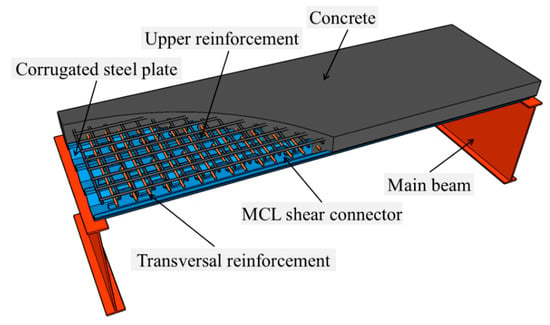
Figure 1.
Schematic diagram of the corrugated steel–concrete composite bridge deck.
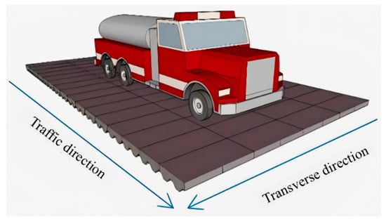
Figure 2.
Schematic of traffic direction for the composite bridge deck.
Figure 3 shows the structural dimensions of the corrugated steel–concrete composite bridge deck specimen. Following the design from the reference [26], four full-scale corrugated steel composite bridge decks, designated as Deck-1 through to Deck-4, were fabricated to study their flexural performance. The proposed steel–concrete composite bridge deck is primarily applied to steel plate girder bridges and steel truss girder bridges. In steel plate girder bridges and steel truss girder bridges, the spacing of the main girders typically ranges from 2 to 6 m, with 3 m being the most commonly used span. Therefore, the specimen design is based on the span lengths and structural parameters of the corrugated steel–concrete composite bridge deck commonly employed in practical engineering. All specimens shared the same dimensions with a corrugated steel bottom plate thickness of 6 mm, differing only in the distance between the loading points and the support points.

Figure 3.
Dimensions of the composite bridge deck specimens (unit: mm): (a) front view; (b) top view; and (c) side view.
The specimen design was primarily based on the Chinese highway bridge design codes [27,28]. Based on the axle weight and tire contact area dimensions specified for the highway-class I vehicle load in the codes, and considering the most unfavorable loading positions along with an impact factor of μ = 1.3, the design bending moment was calculated. Based on the plane section assumption and the ideal elasto-plastic constitutive models for steel and concrete, the flexural capacity of the cross-section was estimated. The initial selection of geometric parameters for the cross-section aimed to ensure that its ultimate flexural capacity significantly exceeded the design bending moment, thereby exploring its strength reserve. The spacing and detailing of shear connectors were determined primarily according to their shear resistance capacity and the principle of ensuring full composite action at the steel–concrete interface. For the finalized specimen cross-section, two critical verifications were conducted: the flexural capacity and the shear resistance capacity of the shear connectors. The specimen design was governed by flexural strength.
Figure 4 shows the type and structural dimensions of the shear connectors used in the bridge deck. The MCL shape composite dowel shear connector features a semi-open design, consisting of an upper steel dowel and a lower dowel base. Due to its configuration, it facilitates the installation of penetrating reinforcement and exhibits favorable mechanical performance [29,30]. After the concrete was cast and cured, a concrete dowel was formed, which worked together with the steel dowel and the penetrating reinforcement to resist shear forces. The shear connector had a thickness of 14 mm and a length of 3000 mm, while the transversal reinforcement had a diameter of 16 mm and a length of 940 mm.

Figure 4.
Structural dimensions of MCL shape shear connector.
Figure 5 illustrates part of the specimen fabrication process. The MCL shape composite dowel shear connectors were produced by splitting a steel plate into two parts using single-wire cutting. The corrugated steel bottom plate was formed using a computer-numerical-controlled (CNC) bending machine. The shear connectors were then welded to the troughs of the corrugated steel plate. The semi-finished specimens, welded in the factory, were transported to the site for tying the ordinary reinforcement, followed by concrete casting and curing.
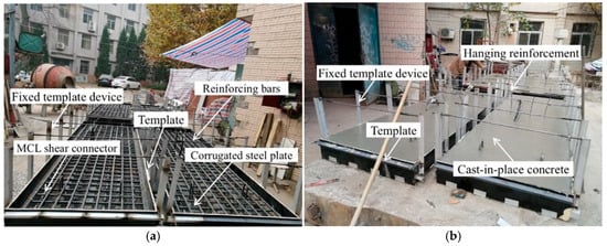
Figure 5.
Specimen fabrication process: (a) Setting formwork and binding reinforcement; and (b) concrete casting.
2.2. Load and Test Program
Figure 6 shows the test setup for specimen loading. A 2000 kN hydraulic jack was used for load application. The loading was applied in a two-point symmetric configuration. The two-point symmetric loading scheme was adopted to create a pure bending region between the two loading points. Within this region, the bending moment reaches its maximum constant value, while the shear force remains zero. This stress state is most effective for investigating the fundamental flexural behavior, failure mechanism, and ultimate bending capacity of the composite section itself, as it avoids interference from complex shear-bending coupling effects. The load was first transferred from the jack to a spreader beam, then to two transverse transfer beams, and finally to the specimen. The transfer beams were designed with sufficient stiffness to ensure a uniform load distribution across the specimen width. They were also made wide enough to prevent local bearing failure at the loading points, which could compromise the test results. To simulate the mechanical behavior of the bridge deck under varying combinations of bending moment and shear force, different shear spans were set for the four deck specimens: 1200 mm, 1000 mm, 800 mm, and 600 mm for Deck-1 through to Deck-4, respectively. These shear span ratios essentially cover the load-bearing range of common bridge deck structures.
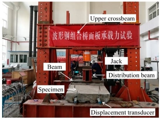
Figure 6.
Load setup of specimens.
Figure 7 illustrates the schematic of the stepwise loading procedure. Prior to loading, the loading and support positions were verified. Upon confirmation, preloading was initiated. Preloading served to eliminate the influence of inelastic deformation on the test results and allowed for the operational check of all loading instruments and measuring devices. After preloading was completed, the specimen was unloaded, and all instruments and measurement devices were reset to zero. The preloading cycle was repeated three times, with the load applied during each cycle set at 30% of the estimated ultimate load. Formal loading followed a graded incremental scheme. During the elastic stage, a larger load increment of 20 kN was employed to enhance testing efficiency and clearly define the stiffness line. Upon entering the nonlinear stage, a smaller load increment of 10 kN was adopted to capture, with higher density, the load levels corresponding to key behavioral transitions, such as concrete crack propagation and steel yielding. A holding period of 2 min was maintained after the application of each load stage. This duration allowed for stress redistribution within the structure, facilitated the full development of cracks for observation and mapping, and ensured that readings from all sensors (particularly displacement and strain gauges) stabilized, thereby guaranteeing the accuracy and consistency of data acquisition. As the specimen approached failure, a continuous slow-rate loading method was adopted to ensure the accuracy of the test data.

Figure 7.
Schematic of stepwise loading.
2.3. Measurement Content and Point Arrangement
Figure 8 shows the layout of measurement points on the specimen. The test measurements mainly included: (1) Vertical deflection of the corrugated steel composite deck. Two displacement transducers, DC1 and DC2, were installed at the bottom of the corrugated steel plate at the mid-span section to measure vertical deflection. This provided the deflection curve of the deck under load, allowing for analysis of stiffness degradation as cracks developed. (2) Relative slip between the corrugated steel bottom plate and the concrete slab. Due to differing deformations of the steel and concrete under load, four displacement transducers (DE1-1, DE1-2, DE2-1, DE2-2) were placed at both ends of the specimen to measure relative slip and evaluate the longitudinal shear performance of the MCL shape composite dowel shear connectors. (3) Strain distribution of the bridge deck. Strain gauges CT1, CT2, CM1, CM2, CB1, and CB2 were used to measure the strain in the concrete slab at the mid-span section. Gauges SB1–SB4 were installed at the troughs of the corrugated steel bottom plate, ST1–ST3 at the crests of the corrugated steel top plate, and SM1–SM6 on the web at the mid-height of the corrugated steel plate.

Figure 8.
Arrangement of measurement points.
2.4. Material Properties
Concrete test blocks were cast during specimen fabrication and cured under the same conditions as the main specimens. According to the testing methods specified in the code [31] for mechanical properties of concrete, the average compressive strength of the concrete cube samples was measured to be 54.5 MPa. Figure 9 and Table 1 show the geometry and dimensions of the steel plate mechanical property test specimens. The preparation and testing procedures followed the standard for metallic materials-tensile testing at room temperature [32]. The corresponding test results are provided in Table 2.
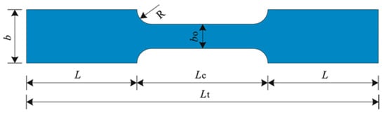
Figure 9.
Structural dimensions of mechanical property test specimens.

Table 1.
Specimen Geometry and Dimensions for Steel Mechanical Property Tests (unit: mm).
Table 2.
Material properties of steel.
3. Experimental Results Analysis
3.1. Failure Mode
Figure 10a illustrates the failure mode of the specimens. During the initial loading stage, no significant phenomena were observed in the specimen. Displacement gauges installed at the mid-span section indicated initial deflection of the composite deck slab, while the gauges positioned on both sides of the deck showed no notable change. The corrugated steel bottom plate and the concrete worked together through shear connectors to resist the applied loads. During loading, intermittent cracking sounds were first heard from inside the specimens, indicating the initiation of internal cracks in the concrete. However, no visible signs or noticeable deformation were observed on the surface of the specimen. Subsequently, visible cracks appeared near the external loading points and propagated obliquely upward from the bottom. At this stage, the deflection began to increase at an accelerating rate. The cracks extended diagonally near the loading points, penetrating from the bottom to the top. Local crushing of concrete was also observed at some loading points. After reaching its ultimate bearing capacity, the deck slab began to show a decline in load resistance while the deflection continued to increase rapidly. During this stage, both the growth in deflection and the decrease in load occurred at a high rate. All four specimens exhibited a similar failure process, characterized primarily by concrete shear failure. However, since shear failure is generally not preferred in practical design, further optimization of the detailing of this composite deck remains necessary in future studies. To ensure sufficient ductility and early warning capacity under ultimate limit states, a preferable design objective is to promote a more ductile flexural failure mode. This can be achieved by refining the specimen design in two aspects: adjusting the reinforcement layout of the concrete slab and fine-tuning the geometric parameters of the composite section. Based on the existing longitudinal reinforcement, increasing the density of shear stirrups or adding diagonal bars within the shear span—particularly between the loading point and supports—is recommended. This directly enhances the concrete’s resistance to principal tensile stress. It delays the propagation of diagonal cracks and shifts the failure mode towards the mid-span pure bending region. Alternatively, increasing the thickness of the concrete slab can provide greater space for arranging shear reinforcement. Optimizing the height of the corrugated steel plate is another viable approach.


Figure 10.
Failure characteristics of specimens: (a) cracks at the loading points; (b) crushed concrete; (c) cracks in the pure bending region; and (d) relative slip at the slab ends.
Figure 10b shows the crack distribution in the pure bending region of the specimens. After diagonal cracks formed near the loading points, additional cracks developed uniformly within the pure bending zone as the load increased. The observed diagonal cracks were relatively wide and long. In the mid-span pure bending region, where only bending moment acts, the cracks were predominantly vertical, fine, and relatively short. At ultimate load, the crack patterns in the pure bending zone were essentially identical across all four specimens. The crack spacing corresponded closely to the spacing of the ordinary reinforcement, indicating that crack formation in this region is closely related to the distribution of the reinforcing bars.
Figure 10c presents the relative slip between the corrugated steel plate and the concrete slab at the specimen ends. In the early loading stages, the steel and concrete acted as a fully composite section with no measurable relative slip. As loading progressed, displacements were recorded by transducers DE1-1(2) and DE2-1(2) installed at both ends, though no visually detectable slip was observed. At ultimate load, relative slip was measured in all four decks, with average values of 0.94 mm, 0.92 mm, 1.09 mm, and 1.16 mm, respectively. Given the very small magnitude of slip at failure, the composite action between the corrugated steel plate and the concrete slab remained reliable throughout the test. This demonstrates that the MCL-type composite dowel shear connectors provide effective shear resistance, ensuring robust interaction and force compatibility between the steel and concrete components.
In corrugated steel–concrete composite bridge decks, the concrete slab is subject to dual restraint from the bottom corrugated steel plate and the shear connectors, which significantly inhibits its free shrinkage deformation. Consequently, complex secondary internal forces and potential damage are induced within the structure. When concrete undergoes shrinkage or temperature drop, its intended free shrinkage deformation is substantially restrained by the bottom corrugated steel plate and the shear connectors. This restraint generates tensile stress within the concrete slab and shear stress at the steel–concrete interface [33]. This restraining effect may lead to two primary consequences: First, micro-cracks may develop within the concrete slab even before loading, reducing its initial stiffness and tensile strength. Second, accumulated shear stress at the interface may weaken the bond or even cause local debonding, adversely affecting the collaborative performance of the shear connectors under load [34].
3.2. Load-Deflection Curves
Figure 11 shows the load–deflection curves of the specimens. Table 3 summarizes the test results at key characteristic stages throughout the loading process. In the table, Pcr denotes the load at which cracks first appeared on the side surface of the concrete slab; Py represents the load when the corrugated steel bottom plate yielded; δy is the mid-span deflection corresponding to the yield load; Pu is the ultimate load capacity of the deck; and δu is the mid-span deflection at the ultimate load.
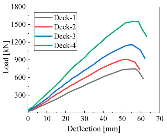
Figure 11.
Load–deflection curves.
Table 3.
Results of flexural tests on composite bridge deck specimens.
As shown in Figure 11 and Table 3, at the ultimate load Pu, the average mid-span bending moment for the four specimens was approximately 458.2 kN·m. According to the axle load and wheel contact area specified for standard vehicle loads in the design code [24,25], and considering the most unfavorable loading position for a simply supported one-way slab with an impact factor μ of 1.3, the calculated mid-span bending moment was 136.5 kN·m for a calculated span Lc of 3000 mm. The results in Table 3 indicate that the ultimate load-carrying capacity of the tested bridge deck was about 3.36 times the design value, demonstrating a high reserve of strength. It can also be observed that the cracking moment was approximately 1.58 times the design load, confirming that the deck remained entirely within the elastic range under service conditions, which reflects favorable in-service performance. The maximum deflections of the four specimens were 1/53, 1/57, 1/54, and 1/51 of the calculated span length, respectively, all significantly exceeding the code-specified limits. This indicates that this type of bridge deck possesses good ductility.
3.3. Load–Strain Curves
Figure 12a shows the load–strain curves for the upper, middle, and lower measurement points on the side surface of the concrete slab in each specimen. Since the trends of the load–strain curves at the same measurement location were consistent and their values were essentially equal, the curves in the figure represent the average values for each point. For all specimens, the concrete at the upper measurement points was in compression. Throughout the elastic loading stage, the load–strain relationship of the concrete remained linear. As loading continued, the rate of compressive strain development at these points accelerated further, and the slope of the load–strain curves began to decrease. At the middle measurement points of all specimens, the strain initially increased, then decreased, and finally shifted from compressive strain to tensile strain. The corresponding loads at which this strain transition occurred were 352.9 kN, 423.0 kN, 546.6 kN, and 731.9 kN for the four specimens, respectively. At this stage, fine cracks began to appear at the bottom edge of the concrete in each specimen, causing partial concrete at the bottom to cease carrying load. As a result, the neutral axis of the deck shifted upward, moving from its initial position below the middle measurement points to a location above them. The concrete at the lower measurement points of all specimens was in tension, and the tensile strain developed rapidly with increasing load.

Figure 12.
Load–strain curves of (a) the side surface of the concrete slab; and (b) the corrugated steel plate.
Figure 12b shows the load–strain curves for the crest, web, and trough of the corrugated steel plate in each specimen. When the applied loads reached approximately 508 kN, 589 kN, 758 kN, and 1025 kN for the four specimens, respectively, yielding began at the trough of the corrugated steel plate. With further increase in load, the slope of the load–strain curve for the trough gradually decreased, indicating the onset of stiffness degradation in the deck. At ultimate load, the entire trough region had fully yielded. When the applied loads reached about 640 kN, 800 kN, 990 kN, and 1350 kN for the four specimens, respectively, yielding initiated in the web of the corrugated steel plate. The yielding of the web lagged behind that of the trough, demonstrating that yielding progressed gradually from the bottom upward. In contrast, strain development at the crest was relatively slow, and the slope of the load–strain curve remained steep. Even when the load reached its ultimate value, the strain at the crest had not yet attained the yield strain of the steel.
4. Numerical Analysis
4.1. Finite Element Model and Validation
Numerical simulation was carried out using the finite element software ABAQUS 2022. The solver used for the analysis was Dynamic and Explicit, considering both geometric and material nonlinearity. The dynamic explicit algorithm of this solver primarily employs quasi-static analysis. This algorithm does not require equilibrium iterations, resulting in fast computational speed. When the time step size is sufficiently small, no convergence issues arise. Figure 13 shows the finite element model. The computational model consisted of seven parts: concrete, composite dowel shear connectors, corrugated steel bottom plate, penetrating reinforcement, ordinary reinforcement, bearing blocks, and supports. The materials in the model were primarily defined as concrete, steel plate, and reinforcement. The Explicit solver was employed for the finite element analysis. Displacement-controlled loading was applied. To prevent stress concentration, rigid bearing plates were placed at the loading locations. A reference point (“RP”) was defined at the center of each rigid bearing plate, and a prescribed displacement of −70 mm was applied to these reference points. The lowest-order mode of a structure determines its response in static problems. Therefore, the required time for the static response of a structure can be estimated based on its natural vibration period or frequency. It is widely accepted that when the loading duration is set to be at least 10 times the natural vibration period, the solution can be ensured to be quasi-static. To improve computational efficiency, the loading rate was increased so that the analysis time (set to 0.5 s in this model) was shorter than the actual duration of the static test. The amplitude of the loading curve was defined using a Smooth Step function to ensure a smooth application of the load.

Figure 13.
The finite element mode.
The corrugated steel bottom plate, concrete structure, and composite dowel shear connectors were modeled using eight-node 3D solid elements (C3D8R). Ordinary reinforcement and penetrating reinforcement were modeled with two-node 3D truss elements (T3D2). The concrete material was specified as C50, the steel plate as Q345, and the reinforcement as HRB400. Steel bearing blocks and hinge supports were modeled as rigid bodies [35]. Contact interactions were employed to simulate the interface between steel and concrete. The tangential behavior of the contact interface was defined using a penalty friction formulation, with a friction coefficient set to 0.2. This value references the commonly adopted simplified treatment for steel–concrete interfaces in the numerical simulation of composite structures [36,37], aiming to reasonably simulate the transfer of frictional shear forces at the interface after minor slippage occurs. The penetrating reinforcement and ordinary reinforcement were tied to the concrete using an embedded region constraint.
The concrete damaged plasticity (CDP) model was adopted to describe the mechanical behavior of concrete. Typically, the flow potential eccentricity (e), the biaxial/uniaxial compressive strength ratio (σb0/σc0), and the ratio of the second stress invariant on the tensile meridian (K) were set to their default values of 0.1, 1.16, and 0.6667, respectively. Through iterative calibration, the dilation angle ψ was set to 36°, and the viscosity parameter μ was set to 0.0005 to match the test results.
The stress–strain relationship under compression is expressed by Equation (1):
where fc is the mean peak compressive stress; η = εc/εcp; εcp is the compressive strain corresponding to the peak compressive stress (2200 με); and αa (1.9) and αd (1.94) are regression parameters.
The elastic modulus for the transversal reinforcement, corrugated steel plate, and shear connectors was uniformly set as 206 GPa. The yield strength and ultimate strength of the corrugated steel plate and shear connectors were 400 MPa and 510 MPa, respectively, while those of the transverse stiffeners were 440 MPa and 600 MPa, respectively. The steel materials were modeled using the Von Mises isotropic yield criterion and a bilinear isotropic hardening rule to simulate initial yielding and post-yield hardening behavior.
The stress–strain relationship of the steel is expressed by Equation (2):
where Es is the elastic modulus of the steel, ε is the strain of the steel, εy is the yield strain of the steel, fy is the yield stress of the steel, εu is the ultimate strain of the steel, and k is the slope of the hardening stage of the steel, with k = 1.2 GPa.
Figure 14 shows the mesh of the finite element model. To balance computational accuracy, efficiency, and solution stability, a global element size of 20 mm was adopted, with a minimum local element size of 5 mm. Before meshing, each component of the model was appropriately partitioned to ensure that the resulting elements were predominantly hexahedral in shape. During meshing, the Element Shape was set to Hex, the Technique to Sweep, the Algorithm to Medial axis, and the option “Minimize the mesh transition” was enabled.
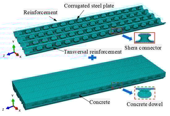
Figure 14.
Depiction of the finite element model.
A mesh sensitivity analysis was conducted based on specimen Deck-2 to determine an appropriate global element size for the finite element model. Three global mesh sizes—10 mm, 20 mm, and 30 mm—were selected and denoted as NAL-10, NAL-20, and NAL-30, respectively. Figure 15 presents the simulated load–deflection curves. The results of the NAL-10 and NAL-20 curves were similar and slightly lower than those of the NAL-30 curve. Considering both computational efficiency and analysis accuracy, a global element size of 20 mm was ultimately selected for the finite element model.
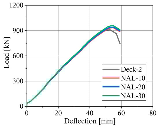
Figure 15.
Mesh sensitivity analysis results.
Figure 16a shows a comparative analysis of the load–deflection curves from the finite element analysis and flexural tests. The finite element analysis results demonstrated good agreement with the experimental outcomes in terms of both the overall trend of the curves and the values of the ultimate load. Figure 16b presents a comparative analysis of the finite element load–strain curve and the experimental results for specimen Deck-2. The finite element analysis results also aligned well with the test data, validating the accuracy of the finite element model.

Figure 16.
Comparison of experimental and numerical results: (a) load–deflection curves; and (b) load–strain curves.
4.2. Load-Carrying Process Analysis
The finite element model based on the bending test of specimen Deck-2 was used to analyze and study the failure process. Three key points on the load–deflection curve from the finite element analysis results were selected for detailed investigation. The study focused on the stress states in specific regions of the corrugated steel plate, shear connectors, and concrete slab when the load reached three critical stages: 0.3Pu, 0.72Pu, and Pu (ultimate load). This approach aims to reveal the local deformation characteristics and failure mechanisms of the structure under critical conditions.
Figure 17a shows the stress distribution in key areas of the corrugated steel plate under a load of 0.3Pu. The corrugated steel plate remained entirely within the elastic stage. The peak tensile stress occurred near the loading points, with a maximum value of approximately 35 MPa. Figure 17b presents the stress distribution in key areas of the corrugated steel plate under a load of 0.72Pu. At this stage, portions of the corrugated steel plate had entered the plastic stage. Figure 17c illustrates the stress distribution in key areas of the corrugated steel plate when the load reached Pu. The overall stress level in the steel plate was significantly higher compared to the previous two stages. Throughout the loading process, all regions of the corrugated steel plate exhibited noticeable tensile stresses. These tensile stresses were primarily concentrated in the pure bending region and gradually diminished within the shear span. The internal stress distribution of the corrugated steel plate showed a distinct difference between the troughs and crests. Stress concentration was evident in the trough regions, which sustained much higher tensile stresses than the crests. From the trough to the crest, the tensile stress gradually decreased. The stress levels among different troughs were generally similar, though the two central troughs experienced slightly higher stresses with a larger area of high-stress distribution. As loading progressed and the deck deformed further, the neutral axis shifted upward. This led to a relative increase in tensile stress at the crests, resulting in a more complex local stress distribution.

Figure 17.
Stress distribution of the corrugated steel plate under the load of (a) 0.3Pu; (b) 0.72Pu; and (c) Pu.
Figure 18a shows the stress distribution of the composite dowel shear connectors under a load of 0.3Pu. The local maximum tensile stress was approximately 160 MPa, which is well below the yield strength of the steel. Therefore, all shear connectors remained in the elastic stage at this load level, with no plastic deformation or premature failure observed. Figure 18b illustrates the stress distribution of the composite dowel shear connectors under a load of 0.72Pu. At this stage, the stress in the shear connectors increased significantly. However, the stress development in the pure bending region was lower than that in the shear span, indicating that the shear forces in the shear span were primarily resisted by the shear connectors. Localized regions within the shear span entered the plastic stage, but the overall plastic zone remained small, suggesting that the shear connectors continued to transfer shear effectively. Figure 18c presents the stress distribution of the composite dowel shear connectors when the load reached Pu. Within the stress concentration zones in the shear-bending region, the local peak tensile stress exceeded the material yield strength. Moreover, the extent of the high-stress zones continued to expand, forming a distinct plastic zone on one side of the shear connectors.
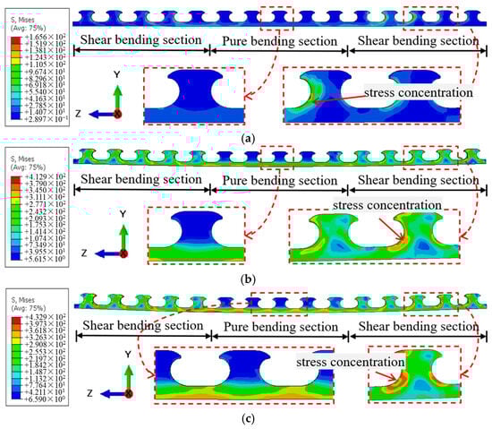
Figure 18.
Stress distribution of the shear connector under the load of (a) 0.3Pu; (b) 0.72Pu; and (c) Pu.
Figure 19a–c shows the tensile damage distribution in the concrete under loads of 0.3Pu, 0.7Pu, and Pu, respectively. At the load level of 0.3Pu, tensile damage was primarily concentrated near the loading points and was relatively minor. In the shear span, the concrete dowel and the steel dowel of the shear connector underwent mutual squeezing and shearing due to longitudinal shear forces, creating a deformation trend that put the concrete in this region under tension. At 0.7Pu, under the influence of positive bending moment, the damaged area at the bottom of the concrete in the pure bending segment increased significantly, leading to a corresponding rise in the number of cracks. The interaction zone between the concrete dowel and the steel dowel of the shear connector within the shear span also expanded, resulting in a larger area of damage. Under the Pu load, the regions exhibiting tensile damage, particularly in the pure bending segment and the shear span near the loading points, showed a marked increase compared to the 0.3Pu and 0.72Pu stages. At this point, the concrete dowel had essentially ceased to function effectively.

Figure 19.
Damage distribution in concrete under the load of (a) 0.3Pu; (b) 0.72Pu; and (c) Pu.
4.3. Parametric Analysis
Based on the finite element model of specimen Deck-2, a parameter analysis was conducted. The parameter ranges were selected with reference to the literature [19,38] and code [27,28].
Figure 20a shows the influence of steel strength on the load–deflection curve. The steel strength grades employed were Q235, Q345, Q390, Q420, and Q460. The yield strength of steel significantly affects the ultimate load. When the steel strength grade decreased from Q345 to Q235, the ultimate load decreased by approximately 18.8%. When the steel strength grade increased from Q345 to Q390, the ultimate load increased by approximately 11.2%. Therefore, with the increase in steel strength, the ultimate load rises. When the steel strength grade further increased from Q390 to Q460, the ultimate load only rose by about 6.0% compared to that of Q345. Thus, once the steel strength exceeds a certain threshold, the growth in ultimate load becomes less pronounced, and the failure stage is notably shortened. This is due to the mismatch between the steel and concrete strength, which prevents the full utilization of the steel’s plastic capacity and leads to a more brittle failure process in the structure.
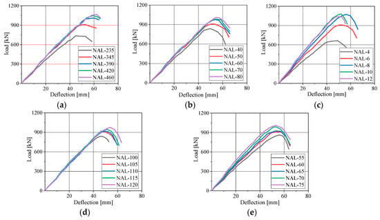
Figure 20.
The load–deflection curves were affected by: (a) steel strength; (b) concrete strength; (c) corrugated steel plate thickness; (d) concrete slab thickness; and (e) the height of the corrugated steel plate.
Figure 20b shows the influence of concrete strength on the load–deflection curve. The concrete strength of the composite bridge deck slabs varied from 40 to 80 MPa with an interval of 10 MPa. The effect of concrete grade on the ultimate load-carrying capacity of the deck was only observable to a certain extent. Although increasing the concrete strength can enhance the bearing capacity of the deck to some degree, the structural performance of the corrugated steel plate does not improve correspondingly, which makes it difficult to fully utilize the strength advantage brought by the concrete.
Figure 20c illustrates the influence of corrugated steel plate thickness on the load–deflection curve. The thickness of the corrugated steel plate varied from 4 to 12 mm with an interval of 2 mm. The effect of plate thickness on the ultimate bearing capacity of the structure was relatively complex. When the thickness of the corrugated steel plate was reduced from 6 mm to 4 mm, the ultimate load decreased by approximately 27.0%. When the thickness was increased from 6 mm to 8 mm, the ultimate load increased by approximately 18.1%. Therefore, as the plate thickness increased, the local stiffness improved, leading to a slight initial enhancement in the ultimate load. When the thickness of the corrugated steel plate increased from 8 mm to 10 mm, the ultimate load only increased by approximately 1.1%. When the thickness further increased from 10 mm to 12 mm, the ultimate load actually decreased by about 4.7%. Therefore, when the plate thickness continued to increase, the overall load-carrying capacity of the deck decreased instead. This occurred because, initially, thickening the corrugated steel plate helped improve the plastic behavior of the steel, delaying the onset of plasticity in the material and thereby retarding cracking in the concrete structure. However, excessively thick plates caused the neutral axis to shift upward, reducing the effective cross-sectional area of concrete in compression. As a result, the concrete prematurely ceased to function, ultimately leading to the overall failure of the deck.
Figure 20d shows the influence of concrete slab thickness on the load–deflection curve. The thickness of the concrete slab varied from 100 to 120 mm with an interval of 5 mm. The effect of changes in concrete slab thickness on the ultimate load-carrying capacity and deflection of the structure was relatively straightforward. As the thickness of the concrete slab increased, the overall load-carrying capacity of the structure exhibited an approximately linear upward trend. However, because increasing the concrete slab thickness also brings about an increase in self-weight, the improvement in load-carrying capacity resulting solely from increasing the slab thickness is not pronounced.
Figure 20e illustrates the influence of the height of the corrugated steel plate on the load–deflection curve. The height of the corrugated steel plate varied from 55 to 75 mm with an interval of 5 mm. When the corrugation height decreased from 65 mm to 55 mm, the ultimate load decreased by approximately 7.0%. When the corrugation height increased from 65 mm to 70 mm, the ultimate load increased by approximately 6.8%. As the height of the corrugated steel plate increased, its sectional moment of inertia improved significantly, which helps to utilize the tensile performance of the steel and enhances local stiffness, thereby initially increasing the ultimate load-carrying capacity of the structure. When the corrugation height increased from 70 mm to 75 mm, the ultimate load only rose by approximately 2.1%. This is because as the height continues to increase, the trough region of the corrugated steel plate inevitably sustains higher tensile stresses, which can easily lead to uneven stress distribution across the section. This uneven distribution causes premature cracking in the concrete, resulting in a non-monotonic trend in the overall load-carrying capacity. Therefore, a moderate height of the corrugated steel plate should be selected in design.
4.4. Design Recommendation
The experimental findings indicate that the ultimate bearing capacity of the corrugated steel–concrete composite deck was approximately 3.36 times its design value (based on Chinese highway bridge load codes), demonstrating a substantial safety reserve. This exceeds the typical safety factors prescribed in many international codes, suggesting that conventional design approaches for composite beams, which often employ simplified models, might be overly conservative for this efficient structural form.
Furthermore, the observed concrete shear failure mode highlights a key design consideration. While some advanced standards (e.g., AISC specifications) acknowledge the combined shear contribution of steel and concrete, our parametric analysis revealed more complex interactions. For instance, increasing the steel plate thickness did not monotonically improve capacity due to shifts in the neutral axis. This indicates that the unique composite action in corrugated decks, mediated by shear connectors, requires tailored design guidance beyond simplified code equations.
Since the ultimate failure is governed by concrete shear, special attention must be given to the shear reinforcement design in the concrete slab. It is recommended to increase shear reinforcement (e.g., stirrups) in potential shear-span regions to promote a more ductile flexural failure mode. A synergistic combination of parameters should be pursued. The use of steel grades higher than Q345 should be avoided, as it yields diminishing returns on ultimate capacity and may compromise ductility. The thickness of the corrugated steel plate had an optimal range; excessive thickness can precipitate undesirable concrete crushing failures. The fact that the steel at the crest of the corrugation remained elastic at failure suggests underutilization. To improve economic efficiency, the corrugation height can be appropriately increased to raise the sectional moment of inertia and achieve a more uniform stress distribution.
It should be noted that this study was limited to the simply supported one-way slab loading mode and did not encompass all possible support conditions, such as continuous beams or cantilever beams. In future research, additional specimens will be fabricated to evaluate the mechanical performance of the bridge deck under different support conditions and loading configurations.
5. Conclusions
In this study, experimental and numerical analyses were conducted to evaluate the mechanical properties of corrugated steel–concrete composite bridge decks with composite dowel shear connectors. The following conclusions were drawn:
- (1)
- The flexure tests indicate that all four specimens were subjected to concrete shear failure. During the loading process, the relative slip between the concrete slab and the corrugated steel plate was minimal, resulting in a reliable composite action.
- (2)
- The load–deflection curves for all specimens exhibited similar trends. At the ultimate load, the average mid-span bending moment of the four specimens was approximately 458.2 kN·m, which is about 3.36 times the design value, indicating that this type of bridge deck possesses high load-bearing capacity. Furthermore, the maximum deflection significantly exceeded the design value, confirming its favorable ductility.
- (3)
- A finite element model was developed, which accurately predicted the load–deflection curves and load–strain curves for the corrugated steel–concrete composite bridge decks. The finite element model was used for the load-carrying process and parametric analysis.
- (4)
- The plastic stage of the specimen commenced at the valleys of the corrugated steel plate near the loading points. Subsequently, the yielded zones propagated both longitudinally and transversely. At the ultimate load, only the valleys and portions of the webs had yielded, while the peaks of the corrugated plate remained elastic. The load-bearing capacity of the bridge deck was influenced by parameters including the steel grade, concrete grade, thickness of the steel plate and concrete slab, and the depth of the corrugated steel plate. In engineering design, these parameters must be rationally coordinated to fully exploit the structural potential.
Author Contributions
Methodology, F.K., R.B., J.H., M.L. and Z.W.; Software, F.K. and R.B.; Validation, J.H.; Resources, F.K., R.B., M.L. and Z.W.; Writing—review & editing, R.B., M.L. and Z.W. All authors have read and agreed to the published version of the manuscript.
Funding
This work was supported by the Transportation Technology Innovation Program Project of Shandong Province, China (Grant No. 2024B110-04), the Key R&D Program of Shandong Province, China (Grant No. 2024CXGC010321), the Department of Transportation Research Project of Shaanxi Province, China (Grant No. 2025-89K), and the Natural Science Foundation Project of Shandong Province, China (Grant No. ZR2025QC553).
Data Availability Statement
The original contributions presented in the study are included in the article, further inquiries can be directed to the corresponding author.
Conflicts of Interest
The authors declare no conflicts of interest.
References
- He, G.; Shao, X.D.; Wu, S.W.; Cao, J.; Cai, W.; Zhao, X. Large-scale experimental study on the mechanical behavior of a steel-UHPC composite truss arch under high compressive stress state after cyclic construction. Eng. Struct. 2025, 330, 119881. [Google Scholar] [CrossRef]
- Yang, H.B.; Wang, P.; Karakas, Ö.; Qian, H. State-of-the-art of fatigue performance and estimation approach of orthotropic steel bridge decks. Structures 2024, 70, 107729. [Google Scholar] [CrossRef]
- Chen, Y.T.; Zhang, Y.C.; Yu, M.F.; Hu, X.; He, W.; Qin, K.; Zhu, Y.; Wei, X. Structural Design and Mechanical Behavior Investigation of Steel–Concrete Composite Decks of Narrow-Width Steel Box Composite Bridge. Buildings 2024, 14, 912. [Google Scholar] [CrossRef]
- Miao, L.C.; Chen, Z.Y.; Song, J.L.; Zhang, Q.; Cui, C.; Li, J. Numerical study on the effects of the mechanical degradation of UHPC layer and stud connectors on the fatigue performance of steel-UHPC composite bridge decks. Eng. Struct. 2025, 332, 110069. [Google Scholar] [CrossRef]
- Huang, Y.F.; Chen, L.J.; Wang, Q.; Liu, W.; Han, D.; Wu, Q. Transverse bending and tensile performance of studs in composite twin-I girder bridge. Structures 2025, 73, 108362. [Google Scholar] [CrossRef]
- Shanmugasundaram, N.; Praveenkumar, S.; Ashwin, K.P.S. Structural behavior of engineered cementitious composite substrate slab overlays for bridge deck and pavement applications. Constr. Build. Mater. 2025, 459, 139736. [Google Scholar] [CrossRef]
- Shi, Z.; Yang, S.L.; Pu, Q.H.; Zhang, Y. Fatigue performance of orthotropic steel decks in long-span cable-stayed steel-box girder railway bridges. J. Bridge Eng. 2019, 24, 04019035. [Google Scholar] [CrossRef]
- Xing, G.H.; Chang, Z.Q.; Bai, Z.Q. Flexural behaviour of RC beams strengthened with near-surface-mounted BFRP bars. Mag. Concr. Res. 2018, 70, 570–582. [Google Scholar] [CrossRef]
- Cheng, B.; Ye, X.H.; Ye, X.E.; Cao, X.; Mbako, D.D.; Cao, Y. Experimental study on fatigue failure of rib-to-deck welded connections in orthotropic steel bridge decks. Int. J. Fatigue 2017, 103, 157–167. [Google Scholar] [CrossRef]
- Lyu, Z.L.; Jiang, X.; Qiang, X.H. State-of-the-art review on fatigue strengthening solutions in orthotropic steel bridge decks. Structures 2025, 79, 109597. [Google Scholar] [CrossRef]
- Luo, P.J.; Zhang, Q.H.; Bao, Y.; Bu, Y. Fatigue performance of welded joint between thickened-edge U-rib and deck in orthotropic steel deck. Eng. Struct. 2019, 181, 699–710. [Google Scholar] [CrossRef]
- Jiang, F.; Fu, Z.Q.; Ji, B.H.; Wan, L. Fatigue life evaluation of deck to U-rib welds in orthotropic steel deck integrating weldment size effects on welding residual stress. Eng. Fail. Anal. 2021, 124, 105359. [Google Scholar] [CrossRef]
- Kong, F.L.; Huang, P.M.; Han, B.; Wang, X.; Liu, C. Experimental study on behavior of corrugated steel-concrete composite bridge decks with MCL shape composite dowels. Eng. Struct. 2021, 227, 111399. [Google Scholar] [CrossRef]
- Pang, X.D.; Zhang, D.Q.; Yu, C.X.; Liu, C.; Kong, F. Mechanical performance analysis of corrugated steel composite bridge deck. J. Hebei Univ. Eng. (Nat. Sci. Ed.) 2023, 40, 70–76. (In Chinese) [Google Scholar]
- Fu, Z.Q.; Wang, Y.X.; Ji, B.H.; Jiang, F. Effects of multiaxial fatigue on typical details of orthotropic steel bridge deck. Thin Wall Struct. 2019, 135, 137–146. [Google Scholar] [CrossRef]
- Yang, D.; Li, G.; Zhang, J.; Yuan, Y.; Au, F.T. Shear connector performance analysis for composite bridge deck with corrugated steel sheeting. Adv. Struct. Eng. 2025, 28, 1218–1232. [Google Scholar] [CrossRef]
- Liu, S.M.; Zhang, H.; Ding, H.S.; Ren, P. Study on the interface shear performance of corrugated steel-UHPC composite bridge decks with stud shear connectors. KSCE J. Civ. Eng. 2025, 29, 100286. [Google Scholar] [CrossRef]
- Dou, R.F.; Zhao, J.; Shi, L.H.; Weng, D.; Zhou, D.; Zhao, W. Experimental study on the flexural behavior of steel–concrete composite bridge decks withstud–PBL shear connectors. Buildings 2026, 16, 104. [Google Scholar] [CrossRef]
- Chen, Z.Y.; Zhang, Q.H.; Bao, Y.; Deng, P.; Wei, C.; Li, M. Flexural behavior of corrugated steel-UHPC composite Bridge decks. Eng. Struct. 2021, 246, 113066. [Google Scholar] [CrossRef]
- Kim, H.Y.; Yeong, Y.J. Ultimate strength of a steel–concrete composite bridge deck slab with profiled sheeting. Eng. Struct. 2021, 32, 534–546. [Google Scholar] [CrossRef]
- Kong, F.L.; Huang, P.M.; Mei, K.H.; Wang, T. Experimental study of load bearing performance of modified clothoid shape composite dowels. Bridge Constr. 2020, 50, 43–48. (In Chinese) [Google Scholar]
- Liu, S.M.; Wang, P.; Ren, P.F.; Ding, H. Research on the Punching Shear Performance of Steel Grid–UHPC Composite Bridge Decks. Buildings 2025, 15, 3398. [Google Scholar] [CrossRef]
- Wang, Y.T.; Uy, B.; Li, D.X.; Thai, H.-T.; Mo, J.; Khan, M. Behaviour and design of coupled steel-concrete composite wall-frame structures. J. Constr. Steel Res. 2023, 208, 107984. [Google Scholar] [CrossRef]
- Huang, P.M.; Li, X.L.; Mei, K.H.; Zhao, Y. Fatigue tests of composite decks with MCL connectors. Adv. Steel Constr. 2022, 18, 793–803. [Google Scholar]
- Zhang, Z.; Tian, C.K.; Deng, E.F.; Peng, X.; Hu, H.-Y.; Li, F.-R. Fatigue performance and optimal design of corrugated steel–concrete composite bridge deck. Structures 2023, 48, 427–437. [Google Scholar] [CrossRef]
- Huang, P.M.; He, J.L.; Kong, F.L.; Mei, K.; Li, X. Experimental study on the bearing capacity of PZ shape composite dowel shear connectors with elliptical holes. J. Hebei Univ. Eng. (Nat. Sci. Ed.) 2023, 40, 40–76. [Google Scholar] [CrossRef]
- JTG D60-2015; General Specifications for Design of Highway Bridges and Culverts. People’s Transportation Publishing House: Beijing, China, 2015.
- JTG 3362-2018; Specifications for Design of Highway Reinforced Concrete and Prestressed Concrete Bridges and Culverts. People’s Transportation Publishing House: Beijing, China, 2018.
- Kopp, M.; Wolters, K.; Classen, M.; Hegger, J.; Gündel, M.; Gallwoszus, J.; Heinemeyer, S.; Feldmann, M. Composite dowels as shear connectors for composite beams-Background to the design concept for static loading. J. Constr. Steel Res. 2018, 147, 488–503. [Google Scholar] [CrossRef]
- Lacki, P.; Derlatka, A.; Kasza, P.; Gao, S. Numerical study of steel–concrete composite beam with composite dowels connectors. Comput. Struct. 2021, 255, 106618. [Google Scholar] [CrossRef]
- GB/T 50081-2019; Standard for Test Methods of Concrete Physical and Mechanical Properties. Ministry of Housing and Urban-Rural Development of the People’s Republic of China: Beijing, China, 2019.
- GB/T 228.1-2021; Metallic Materials-Tensile Testing-Part 1: Method of Test at Room Temperature. National Steel Standardization Technical Committee: Beijing, China, 2021.
- Al-musawi, H.; Figueiredo, F.P.; Guadagnini, M.; Pilakoutas, K. Shrinkage properties of plain and recycled steel–fibre-reinforced rapid hardening mortars for repairs. Constr. Build. Mater. 2019, 197, 369–384. [Google Scholar] [CrossRef]
- Daneshvar, D.; Deix, K.; Robisson, A.; Shafei, B. Investigation of drying shrinkage effects on sloped concrete-concrete composites. In Computational Modelling of Concrete and Concrete Structures, Proceedings of the EURO-C 2022 Conference, Vienna, Austria, 23–26 May 2022; CRC Press: Boca Raton, FL, USA, 2022; pp. 634–639. [Google Scholar]
- Zhuang, B.Z.; Liu, Y.Q.; Wang, D.L. Shear mechanism of Rubber-Sleeved Stud (RSS) connectors in the steel-concrete interface of cable-pylon composite anchorage. Eng. Struct. 2020, 223, 111183. [Google Scholar] [CrossRef]
- Luo, Y.B.; Hoki, K.; Hayashi, K.; Nakashima, M. Behavior and strength of headed stud-SFRCC shear connection. II: Strength evaluation. J. Struct. Eng. 2016, 142, 04015113. [Google Scholar] [CrossRef]
- Farid, B.; Boutagouga, D. Parametric study of I-shaped shear connectors with different orientations in push-out test. Fract. Struct. Integr. 2021, 15, 24–39. [Google Scholar] [CrossRef]
- Hu, S.; Su, Q.T.; Wu, C. Study on the section optimization of the orthotropic steel-composite bridge deck. Struct. Eng. 2015, 31, 131–137. (In Chinese) [Google Scholar]


Disclaimer/Publisher’s Note: The statements, opinions and data contained in all publications are solely those of the individual author(s) and contributor(s) and not of MDPI and/or the editor(s). MDPI and/or the editor(s) disclaim responsibility for any injury to people or property resulting from any ideas, methods, instructions or products referred to in the content. |
© 2026 by the authors. Licensee MDPI, Basel, Switzerland. This article is an open access article distributed under the terms and conditions of the Creative Commons Attribution (CC BY) license.