Abstract
Real-time monitoring and early warning of foundation pits are critical for geotechnical safety. However, the rainfall-induced hydro-mechanical coupling effects on water-rich sandy excavations remain poorly understood. The impact of rainstorms on excavation stability demands urgent investigation. This study examines the response of a deep excavation at Beijing Daxing Airport during the “31.7” extreme rainfall event using a multi-sensor monitoring network and numerical simulations. Results reveal that excavation-induced displacement features a neutral point at 0.4–0.6H (H = slope height), with retaining pile displacements reaching 0.14%He (He = excavation depth). Extreme rainfall events elevate the groundwater table, triggering a rise in pore-water pressure within the soil mass. This process can induce excessive displacement in the excavation, posing a substantial threat to its overall stability. It is recommended to set the critical groundwater rise threshold for Beijing at 15% of the slope height (H) and to provide a 20% axial load-bearing safety margin for support systems in rainfall-prone areas. The safety threshold established in this study will serve as a scientific basis for early warning systems of excavation safety during extreme weather events.
1. Introduction
In recent years, under the backdrop of global warming, extreme weather events have significantly intensified worldwide [1,2]. According to the China Meteorological Administration, since 2010, extreme precipitation has accounted for 27% of all extreme weather events in China, ranking first among extreme climate events [3]. On 31 July 2023, influenced by the remnant circulation of Typhoon Doksuri moving northward, Beijing experienced a catastrophic “31.7” rainstorm. The highest recorded rainfall in the city occurred at Wangjiayuan Reservoir in Changping, measuring 744.8 mm, marking the greatest instrumentally recorded rainfall in Beijing in the past 140 years [4,5]. Following the extreme rainfall, the groundwater level rose, soil moisture content increased, and the hydraulic properties of unsaturated soils changed [6,7,8,9,10], markedly reducing the contribution of matric suction [11,12] to soil shear strength and posing substantial risks to structural safety. Despite the availability of various analytical models for rainfall-induced seepage in foundation pits [13,14,15], comprehensive monitoring and numerical simulation studies remain imperative.
Research on foundation pit engineering has a long history, yielding well-established findings. Liu et al. [16] proposed an analytical method accounting for multilayer soil to assess excavation-induced disturbances to adjacent buildings. Zhang and Zhao et al. [17,18] developed failure analysis models for existing structures near excavation sites. Lyu [19] established a quantitative formulation for ground settlement analysis that considers the effects of foundation pit dewatering. Furthermore, Harahap and Zhou et al. [20,21] conducted valuable numerical investigations into the interaction between deep excavations and supporting structures. As evidenced by the foregoing research, effective groundwater management is crucial during foundation pit excavation, with most studies concentrating on dewatering strategies [22,23,24]. However, studies on foundation pit responses to rainfall, particularly under extreme weather conditions leading to groundwater level rise, remain scarce. In theoretical studies, Shahrokhabadi et al. (2019) [25] developed an analytical framework incorporating soil pressure variations induced by transient infiltration, while Huang et al. (2019) [26] examined rainfall effects on pile-supported retaining structures using the Richards equation and earth pressure theory. In numerical simulations and experimental studies, several researchers have made significant contributions. For example, Wang et al. (2021) [27] developed a two-dimensional numerical model to study a large metro station on a composite soil-rock foundation under heavy rainfall conditions, and Dong et al. (2017) [28] examined the infiltration characteristics of gravelly soils under rainfall through one-dimensional and two-dimensional seepage tests, proposing three permeability formulas expressed by relevant indicators.
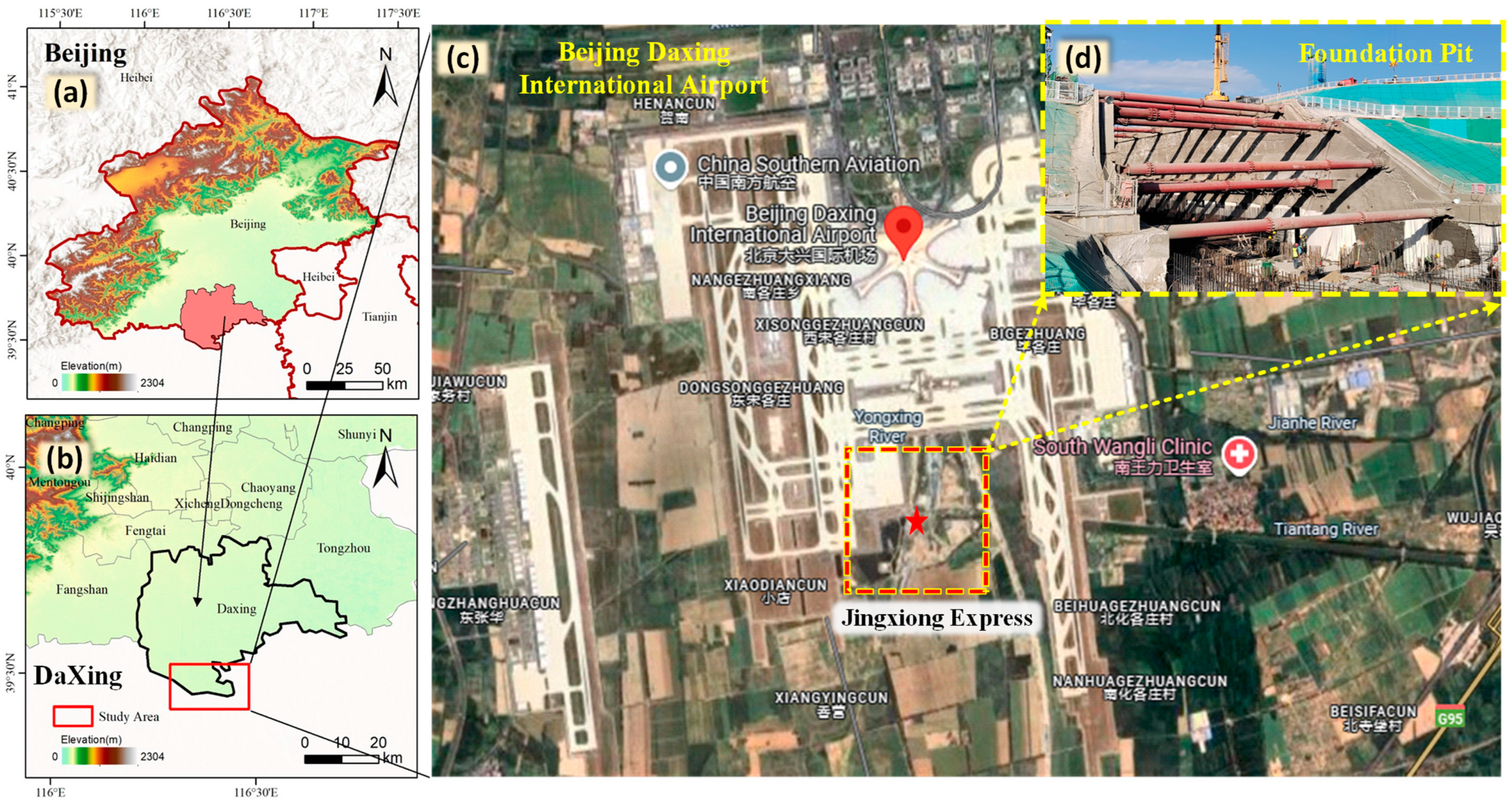
In summary, foundation pit engineering is inherently high-risk, region-specific, and operates with limited safety margins [29,30,31,32]. Therefore, mitigating the effects of extreme weather on foundation pit projects is a pressing challenge in the engineering field. However, there remains a lack of field-validated numerical analyses integrating multi-sensor monitoring data with hydro-mechanical coupling under real extreme rainfall events. Moreover, in the context of intensifying global climate change, monitoring excavations during rare extreme weather events is becoming increasingly crucial. To address this issue, this study investigates a foundation pit project in Beijing’s Daxing District (Figure 1), following the “31.7” catastrophic rainstorm. Using field monitoring data collected before and after the rainstorm, a three-dimensional numerical model incorporating hydro-mechanical coupling effects was developed. The model was employed to investigate the effects of rainfall on soil displacement and support structure deformation, with a critical groundwater level proposed as a hazard threshold. The findings of this research provide both technical guidance and theoretical support for the construction and safe support of deep foundation pit projects under extreme weather conditions.
Figure 1.
Plan view of foundation pit location. (a) Beijing area. (b) Daxing District. (c) Location of foundation pit.
2. Engineering Overview
2.1. Engineering Background
The Xiong’an New Area to Beijing Daxing International Airport Express (Jingxiong Express) is a regional rapid transit line traversing Beijing, Langfang (Hebei Province), and Xiong’an New Area. The mainline section between K155+900 and K156+500 spans 600 m and is located within the third open-cut segment between Yongqing Linkong Station and Daxing Airport Station. The foundation pit adopts a support system consisting of bored piles with a cement mixing pile curtain for groundwater cutoff, with excavation depth (He = excavation depth) ranging from approximately 10.4 to 19.4 m. In some sections, a sloped excavation method or a combination of Φ800 bored piles (spaced at 1400/1600 mm) with cement mixing piles is employed. The excavation boundary is more than 120 m from the operational Jingxiong Intercity Airport Tunnel No. 2 on the west. The surrounding site is open, and the plan view of the alignment is shown in Figure 1.
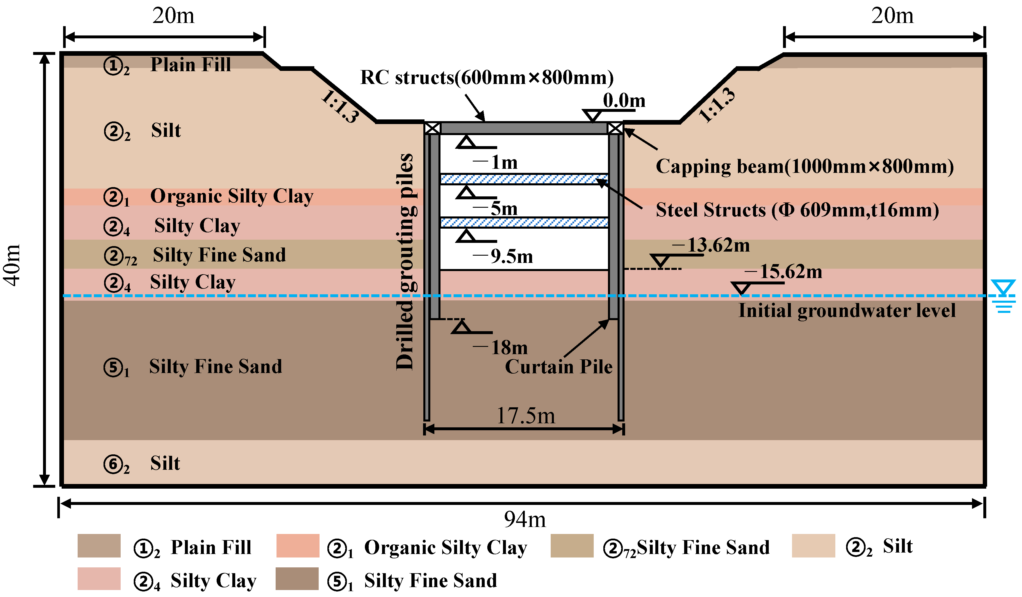
This study selects section 10-10 at YK156+130 along the mainline as a representative site for analysis. The cross-sectional conditions and primary geological strata at this location are shown in Figure 2. The enclosure structure consists of Φ800 bored piles spaced at 1400 mm, while the groundwater cutoff curtain is formed by Φ650 cement mixing piles spaced at 450 mm.
Figure 2.
Profiles of the deep excavation.
2.2. Geological and Hydrogeological Conditions
The project is located in the North China Plain, predominantly characterized by alluvial plains. The terrain is flat and open, with ground elevations ranging from approximately 19.03 to 33.76 m, and a gentle slope from northwest to southeast. All soil parameters used in this research were determined exclusively through direct in situ field testing. The engineering properties of the various geotechnical layers are detailed in Table 1.
Table 1.
Foundation soil layer parameters.
The groundwater in this project is classified as phreatic water. Detailed groundwater level data were acquired from drilling investigations conducted using an SH-30 drill rig in May 2021. The initial observed groundwater depth ranges from 5.30 to 20.60 m, with an elevation of 9.23 to 16.35 m. The stable groundwater depth varies from 4.80 to 20.40 m, with an elevation of 10.13 to 17.15 m. The groundwater is primarily distributed within the silty fine sand layer (②7) and the silt layer (②2). The shallowest groundwater depth is found within the Tiantang River channel, while the deepest is located in the spoil heap area of the site.
3. Field Monitoring
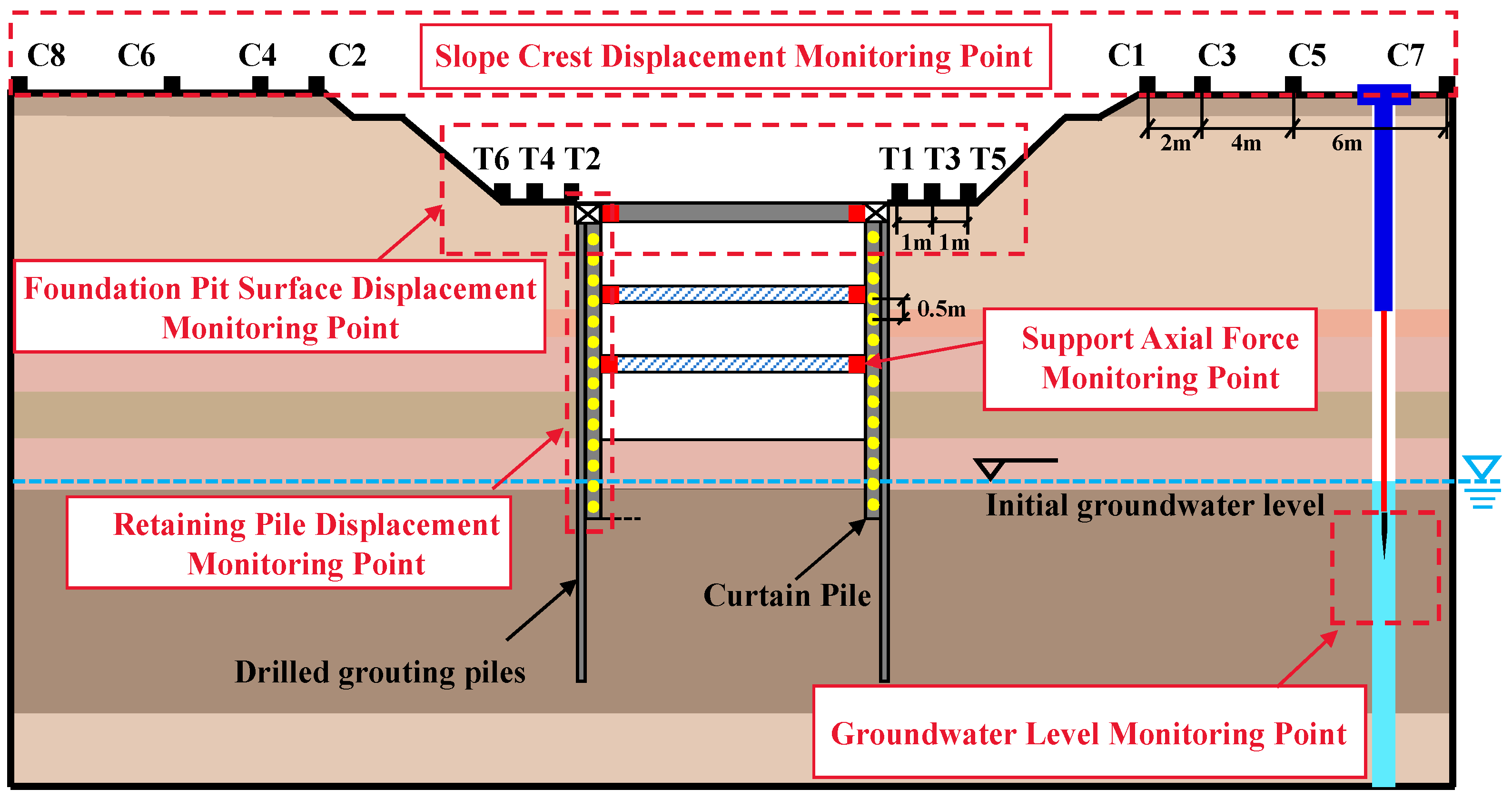
This study employs a comprehensive monitoring system to track key parameters of a deep foundation pit in the Beijing Daxing Airport area during construction. The monitored variables comprise: (1) slope crest settlement at eight locations (C1–C8); (2) foundation pit surface settlement at six points (T1–T6); (3) lateral deformation of retaining piles, measured at 0.5 m intervals along the pile shaft; (4) internal support forces, gauged at both ends of each strut; and (5) groundwater levels, monitored at 5 m intervals along the alignment. The monitoring items, instrument locations, required instrumentation, and measurement accuracy for the excavation are summarized in Table 2.
Table 2.
Monitoring Items, Instruments, and Accuracy.
The objective is to assess the impact of staged excavation and groundwater level rise following rainfall on foundation pit stability. The overall layout of monitoring instruments is shown in Figure 3.
Figure 3.
Sectional view of foundation pit monitoring points.
3.1. Slope Crest and Surface Settlement
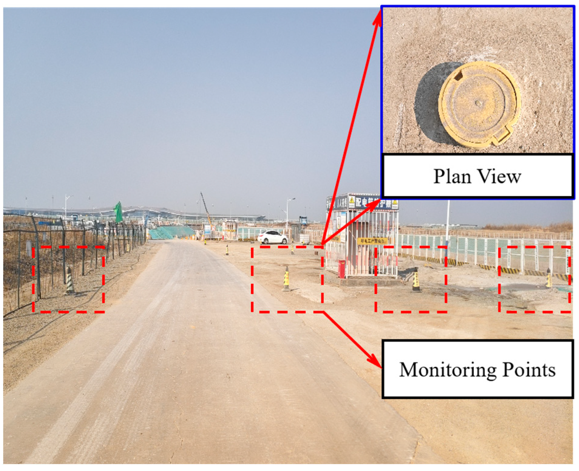
A total of eight settlement monitoring points (C1~C8) were symmetrically installed along the cross-section of the slope crest, with horizontal spacings of 2 m, 4 m, and 6 m.
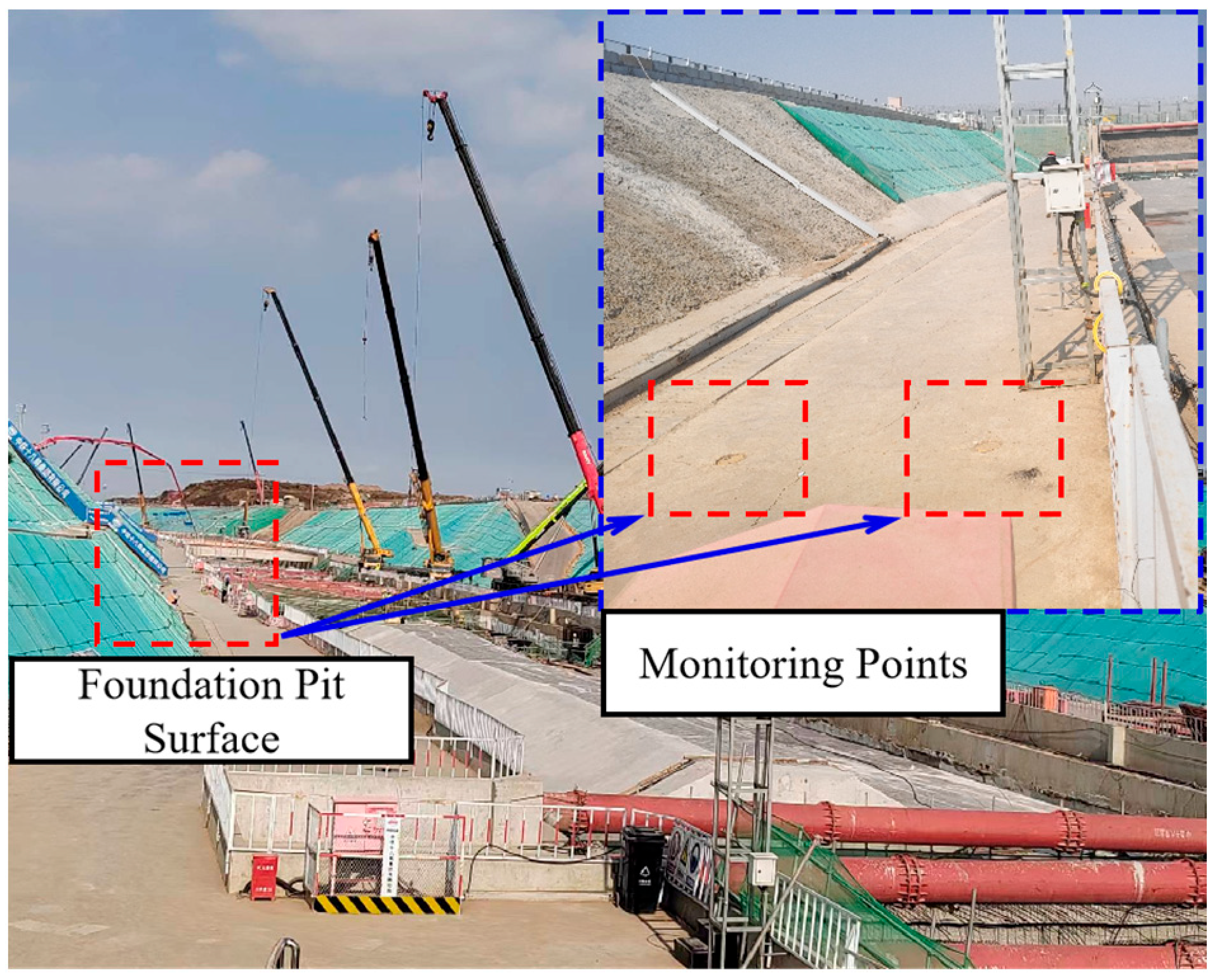
Additionally, six settlement monitoring points (T1~T6) were placed on the foundation pit surface at 1 m intervals. The monitoring layout is illustrated in Figure 4 and Figure 5.
Figure 4.
Slope crest monitoring point.
Figure 5.
Foundation pit surface monitoring point.
3.2. Support Monitoring System
The support system in this project consists of the retaining structure and internal supports.
3.2.1. Monitoring of Retaining Piles
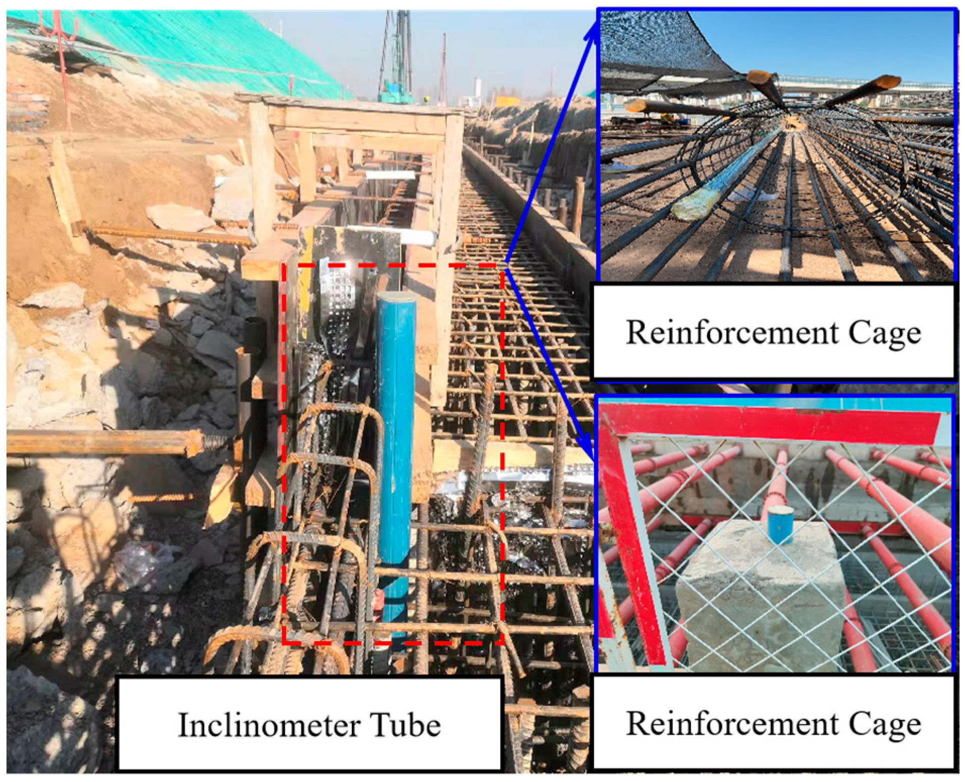
As shown in Figure 6, inclinometer tubes were embedded within the reinforcement cages of the retaining piles to measure lateral deformation after pile casting. Monitoring points were marked at 0.5 m intervals along the pile depth.
Figure 6.
Monitoring layout of retaining pile.
3.2.2. Monitoring of Supports
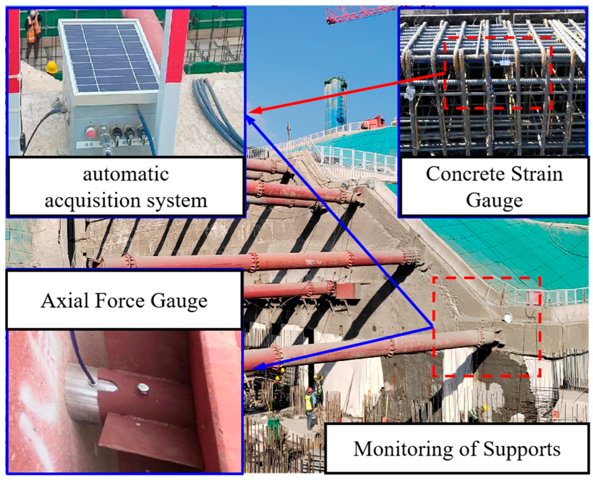
The internal support system consists of a concrete support at the top of the foundation pit and two layers of steel struts. An automatic axial force acquisition system was installed on the struts to monitor their force distribution. The installation of axial force gauges is detailed in Figure 7.
Figure 7.
Monitoring layout of retaining supports.
3.3. Groundwater Level Monitoring
Automated groundwater level monitoring was employed in this study. The monitoring wells were drilled using a geological drilling rig with a borehole diameter of 110 mm. A Φ48 mm filter pipe was installed inside the borehole, and a monitoring probe was used to track groundwater level fluctuations. The layout of the groundwater monitoring points is shown in Figure 8.
Figure 8.
Water level well and water level monitoring.
4. Hydro-Mechanical Coupled 3D Numerical Model
4.1. Model Description
This study utilizes the FLAC3D 6.0 finite difference software to develop a three-dimensional numerical model of section 10-10 at YK156+130 along the Jingxiong Express. The stratigraphic conditions were generalized to represent the geological characteristics of this section accurately.
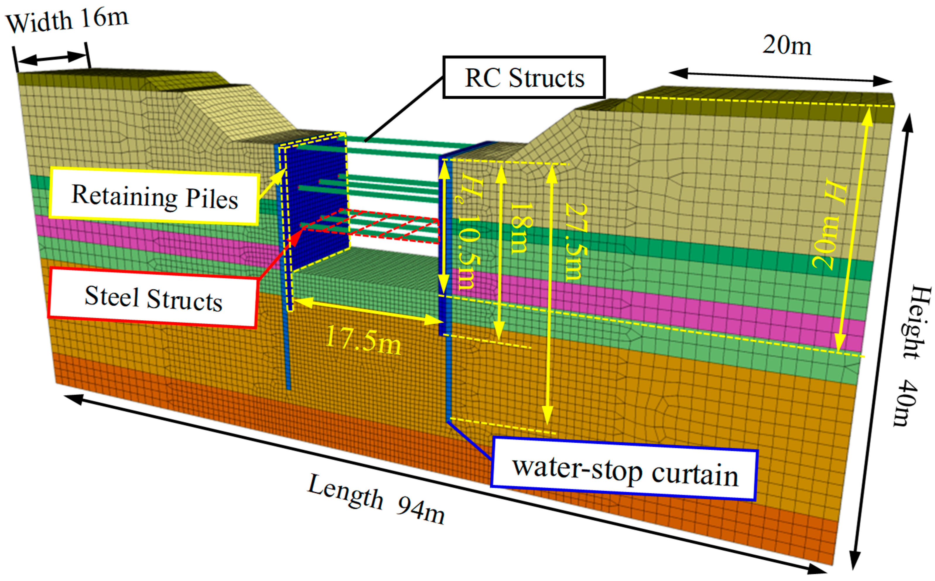
At section 10-10, the foundation pit is supported by both concrete and steel bracing. The first concrete support is a 600 × 800 mm2 concrete brace at 8 m intervals, while the second and third supports are Φ609 × 16 mm steel pipe braces at 4 m intervals. A calculation model unit with a depth of 16 m was created, with each unit containing two concrete braces and three steel braces. To account for the foundation pit’s influence range, the distance from the pit edge to the model’s long boundary is set to three times the maximum excavation depth. The model dimensions are 94 m × 16 m × 40 m (length × width × height).
According to the FLAC3D User Manual and related equivalent calculation methods [28,33], the water-stop curtain, constructed with P.O 42.5 cement-soil mixing piles of length 27.5 m, can be equivalently represented as a retaining wall with a width of 0.65 m. The bored piles, made of C30 reinforced concrete, can be equivalently modeled as retaining walls with a width of 0.8 m. The 3D numerical model of the foundation pit, retaining structure, and supports is shown in Figure 9.
Figure 9.
Geometry and mesh of the numerical model.
For the model mesh, a refined grid with an element size of 0.5 m is applied within one excavation width on both sides, transitioning to a coarser grid of 1.0 m beyond this zone. Regarding the stress field simulation, fixed displacement boundaries are prescribed at the model’s sides and bottom. For post-rainfall seepage analysis, the lateral boundaries are defined as permeable, with pore water pressures fixed at the cross-section. The solution convergence is set to a force imbalance tolerance of 1 × 10⁻⁵.
4.2. Hydro-Mechanical Coupling Method
To investigate the behavior of unsaturated soils under excavation and groundwater rise, the Biot consolidation theory is adopted to account for hydro-mechanical coupling [33], and groundwater flow is described using Darcy’s law.
- The governing equation for the saturated–unsaturated groundwater flow can be formulated as follows:
—the total head;
—the permeability of soils;
—the specific moisture capacity;
—the volumetric moisture content;
—the degree of saturation;
—is the specific storage.
- 2.
- For the specific storage , the compressibility of soil particles can be neglected for simplification, yielding:
—the ratio of the volume of voids to the total volume;
—the water density;
—the gravitational acceleration
—the compression modulus of the air–water mixture
- 3.
- The hydraulic boundary conditions are defined as follows:
—the value of inflow;
—the vector components of the total discharge;
—the outward pointing normal vector components on the boundary.
4.3. Support Beam Elements
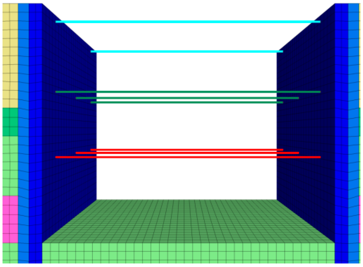
For the concrete and steel supports installed in the foundation pit of this project, the Beam structural element in FLAC3D was used for modeling. The connection between the structural elements and the soil is represented as a Link rigid connection, which constrains the horizontal displacement and rotation of the steel supports and the foundation pit sidewalls. The parameter values for the structural elements and the structure are shown in Table 3 and Figure 10.
Table 3.
Parameter values for support structural elements.
Figure 10.
Structural elements.
4.4. Soil Parameters and Constitutive Models
The constitutive models for soil include various types such as the elastic model, elastoplastic model, hardening strain model, and small strain model [34,35,36]. The accurate determination of geotechnical parameters is crucial for the precision of numerical simulations. Although some studies suggest that the HS (Hardening Soil) model is suitable for simulating foundation pit excavation [33,37], this model requires numerous parameters and specialized tests for determination [38,39,40], which may affect the accuracy of the research because improper determination of these parameters may compromise the reliability of the results. Therefore, in cases where the basic soil parameters can be precisely determined, this study uses the typical Mohr-Coulomb constitutive model for numerical analysis.
Given the inherent variability and uncertainty of soil parameters, values for this study were sourced from in situ tests, with final selections based on sensitivity analyses to ensure reasonable and conservative estimates [21,33]. While the dilatancy angle plays a non-negligible role in sandy soils, a value of ψ = 3° is adopted for the analysis. This selection is based on prior sensitivity studies and accounts for the significant presence of a thick clay layer within the excavation depth [41]. For the retaining structure, the elastic model is used for the numerical analysis. The material parameters for the soil and supports are shown in Table 1, Table 2 and Table 3.
4.5. Model Assumptions and Limitations
The numerical model incorporates several necessary simplifying assumptions to balance computational efficiency with engineering practicality:
- Isotropic Soil Behavior: The soil is assumed to exhibit isotropic deformation under stress. While this assumption may overestimate the overall soil stiffness, it is considered a reasonable and common simplification for this study, which focuses on global vertical settlement rather than localized, detailed deformations.
- Neglect of Time-Dependent Consolidation Effects: The model employs the Mohr-Coulomb elastoplastic constitutive model and does not account for time-dependent behaviors such as creep and consolidation. Consequently, the predicted deformations are instantaneous. This simplification primarily affects the accuracy of long-term deformation predictions. Given that this research concentrates on the short-term excavation response under extreme rainfall, where time-dependent effects are not the controlling factor, this simplification is deemed acceptable.
- Quasi-Static Groundwater Conditions: The groundwater level is assumed to rise steadily with each rainfall time step, and the pore-water pressure distribution is simplified as steady-state. This approach may underestimate the potential instability associated with infiltration in the unsaturated zone and the redistribution of pore-water pressure. However, as the model assumes saturated soil conditions, the methodology adopted is applicable and effective for assessing the controlling influence of the overall groundwater rise on the global stability of the slope.
4.6. Numerical Simulation Setup
This study primarily simulates the deformation effect on the foundation pit and support structure during layered excavation and after excavation, under conditions of extreme rainfall causing a rise in groundwater level. The working conditions for the study are set as shown in Table 4.
Table 4.
Numerical simulation working conditions.
4.6.1. Layered Excavation Working Condition Setup Steps
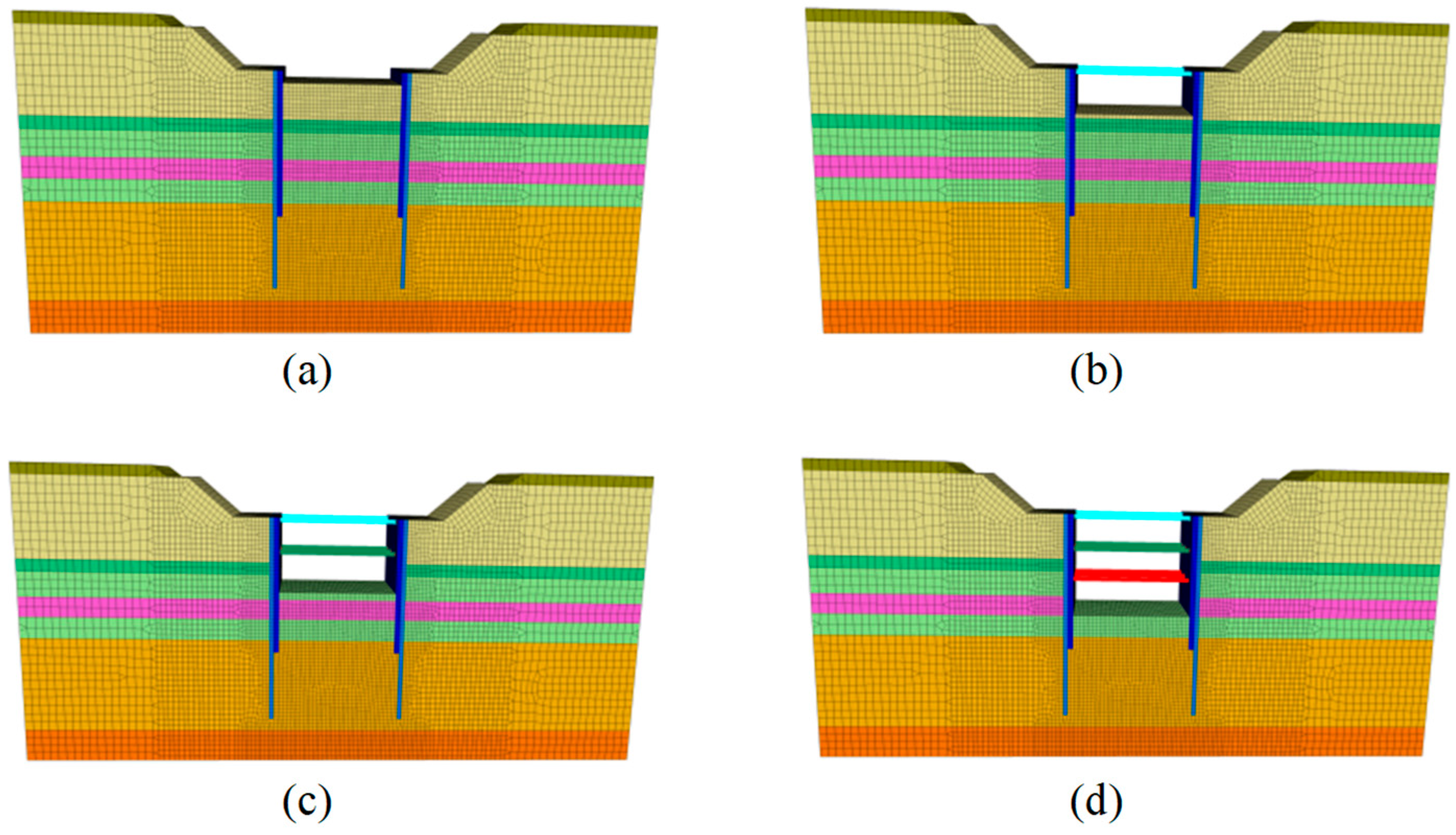
The excavation stages in the numerical simulation are shown in Figure 11.
Figure 11.
Foundation pit excavation simulation. (a) 1st-Excavation. (b) 2nd-Excavation. (c) 3ed-Excavation. (d) 4th-Excavation.
Step 1: Establish the structural model, assign constitutive models to soil layers, diaphragm walls, and water-stop curtains, and balance the initial geostatic stress.
Step 2: Eliminate the displacement and rate fields corresponding to the initial geostatic stress field. In FLAC 3D, the command “initial” can be used to zero the displacement.
Step 3: Excavate the first layer of soil from the foundation pit, setting the bottom elevation to −13.62 m, thus the top of the foundation pit will be at 0 m. Excavate to −1.49 m and compute the structural force balance.
Step 4: Apply the first concrete support using the Beam element, assign elastic constitutive parameters to the material, excavate the pit to −5.45 m, and compute the structural force balance.
Step 5: Apply the second steel pipe support using the Beam element, assign elastic constitutive parameters to the material, excavate the pit to −9.97 m, and compute the structural force balance.
Step 6: Apply the third steel pipe support using the Beam element, assign elastic constitutive parameters to the material, excavate the pit to the bottom elevation of −13.62 m, and compute the structural force balance.
4.6.2. Groundwater Level Rise Setup Steps
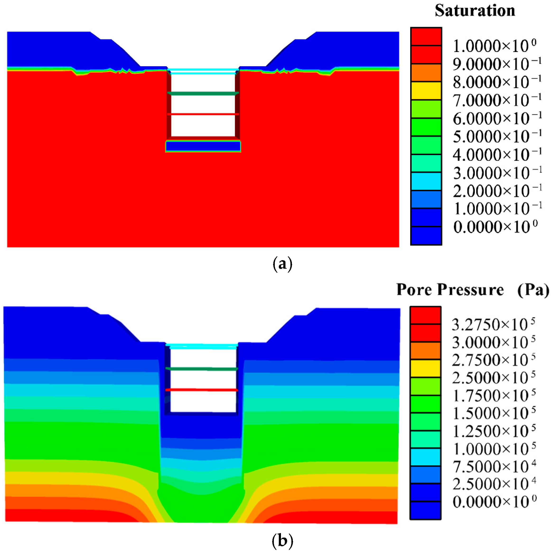
Step 1: Establish the structural model and assign constitutive models to soil layers, diaphragm walls, and water-stop curtains. As shown in Figure 12,the initial water level is set according to the construction drawing section, with the water level on the outside of the water-stop curtain at an elevation of 13.2 m, and the groundwater level at the bottom of the foundation pit set 2 m below the excavation bottom.
Figure 12.
Initial groundwater level contour map (a) Initial Soil Saturation (b) Initial Groundwater Pressure (Pa).
Step 2: Simulate the rise of the groundwater level by 1 m outside the water-stop curtain and perform hydraulic coupling calculations.
Step 3: Simulate the rise of the groundwater level by 2 m outside the water-stop curtain and perform hydraulic coupling calculations.
Step 4: Simulate the rise of the groundwater level by 3 m outside the water-stop curtain and perform hydraulic coupling calculations.
5. Results and Analyses
5.1. Excavation-Induced Response During Layered Construction
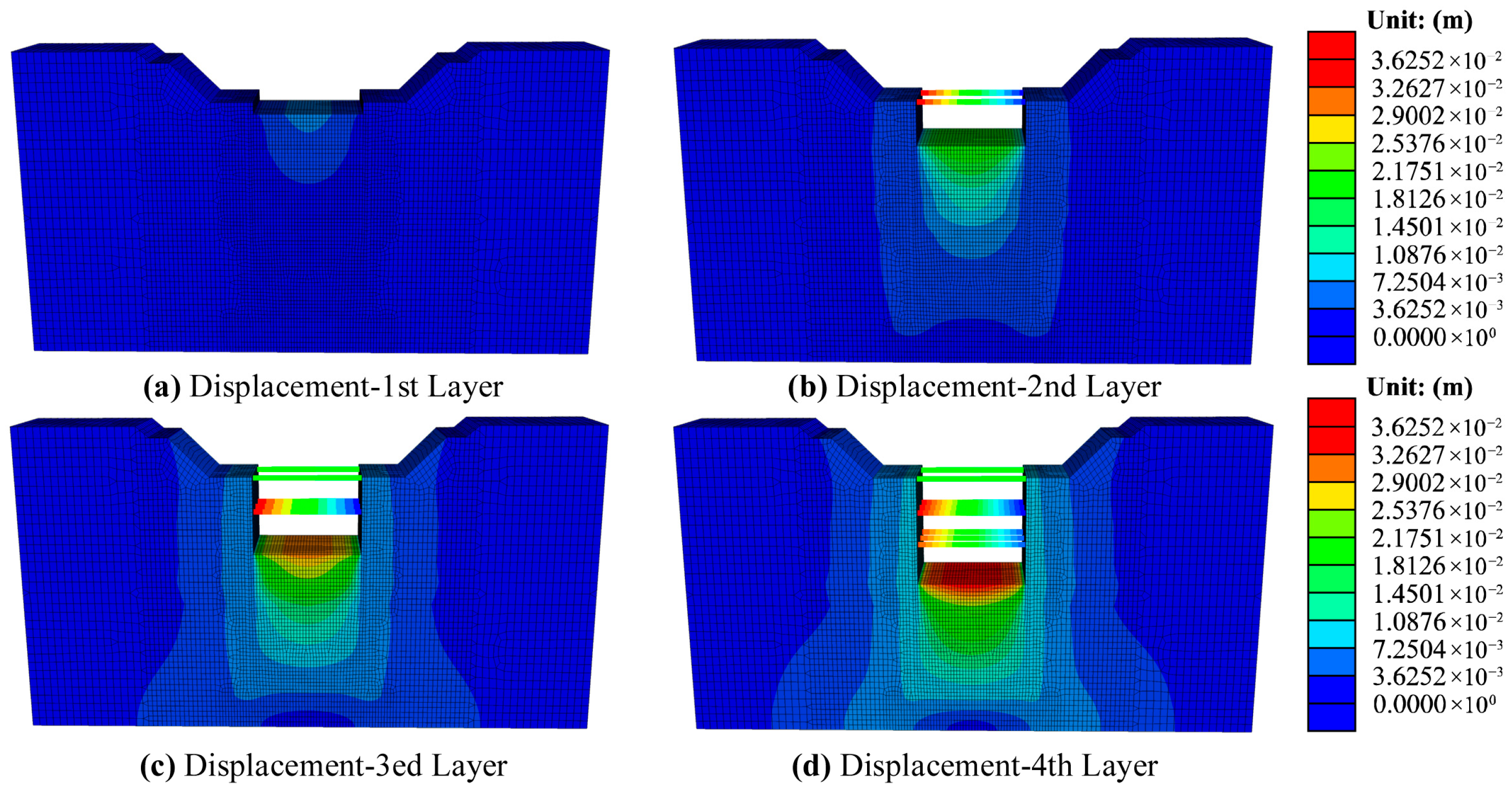
The displacement at each stage of the segmented excavation are shown in Figure 13. From the displacement contour maps, it is evident that after layered excavation, the soil at the bottom of the foundation pit exhibits an upward heave. When the excavation depth reaches twice the excavation depth, soil displacement significantly decreases. Therefore, this study suggests that the displacement influence range of the water-rich sandy foundation pit in this region can be approximately defined as twice the foundation pit width, measured from the center of the pit.
Figure 13.
Displacement contours for staged excavation. (a) 1st Layer. (b) 2nd Layer. (c) 3ed Layer. (d) 4th Layer (m).
5.1.1. Ground Surface Uplift–Subsidence Transition
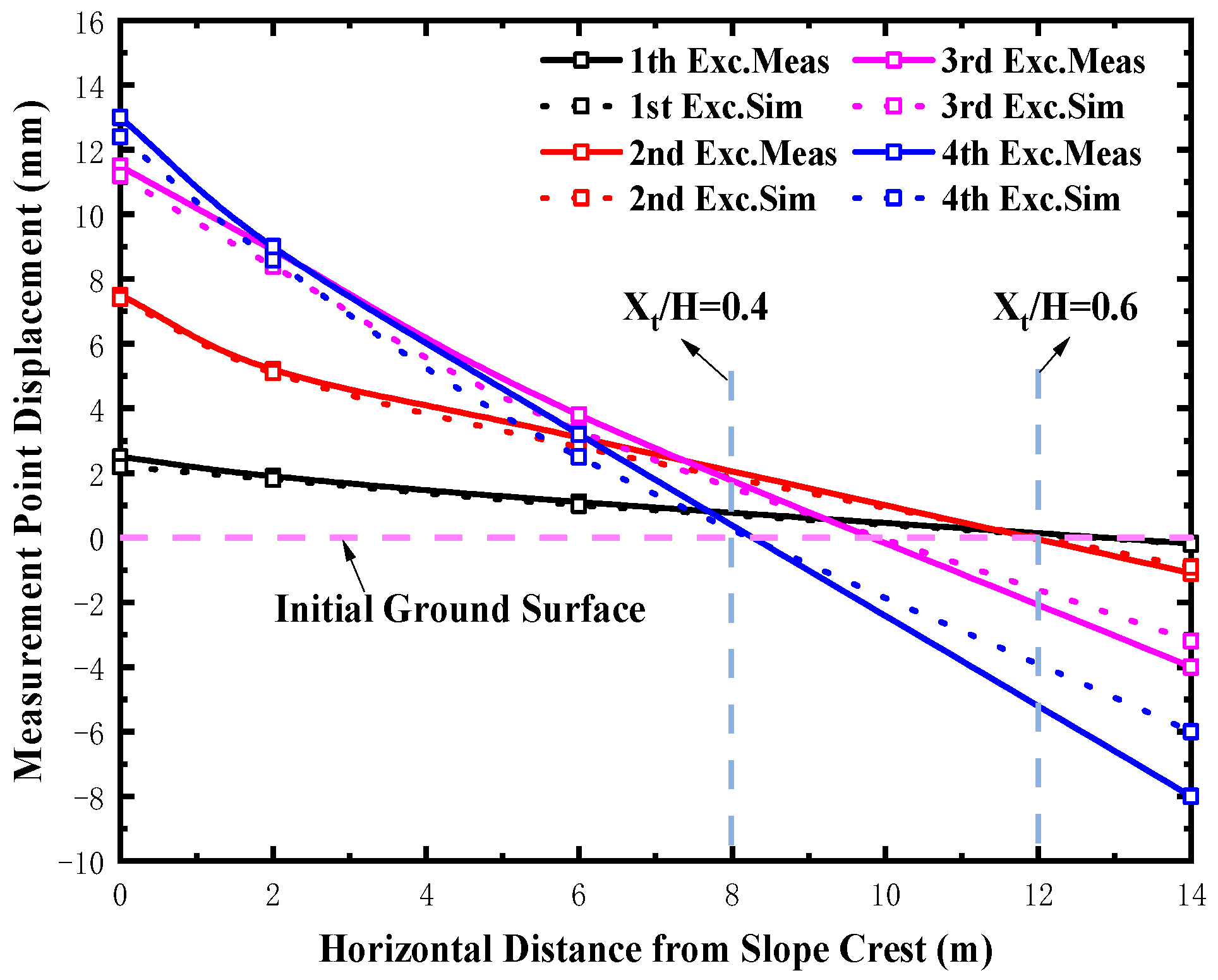
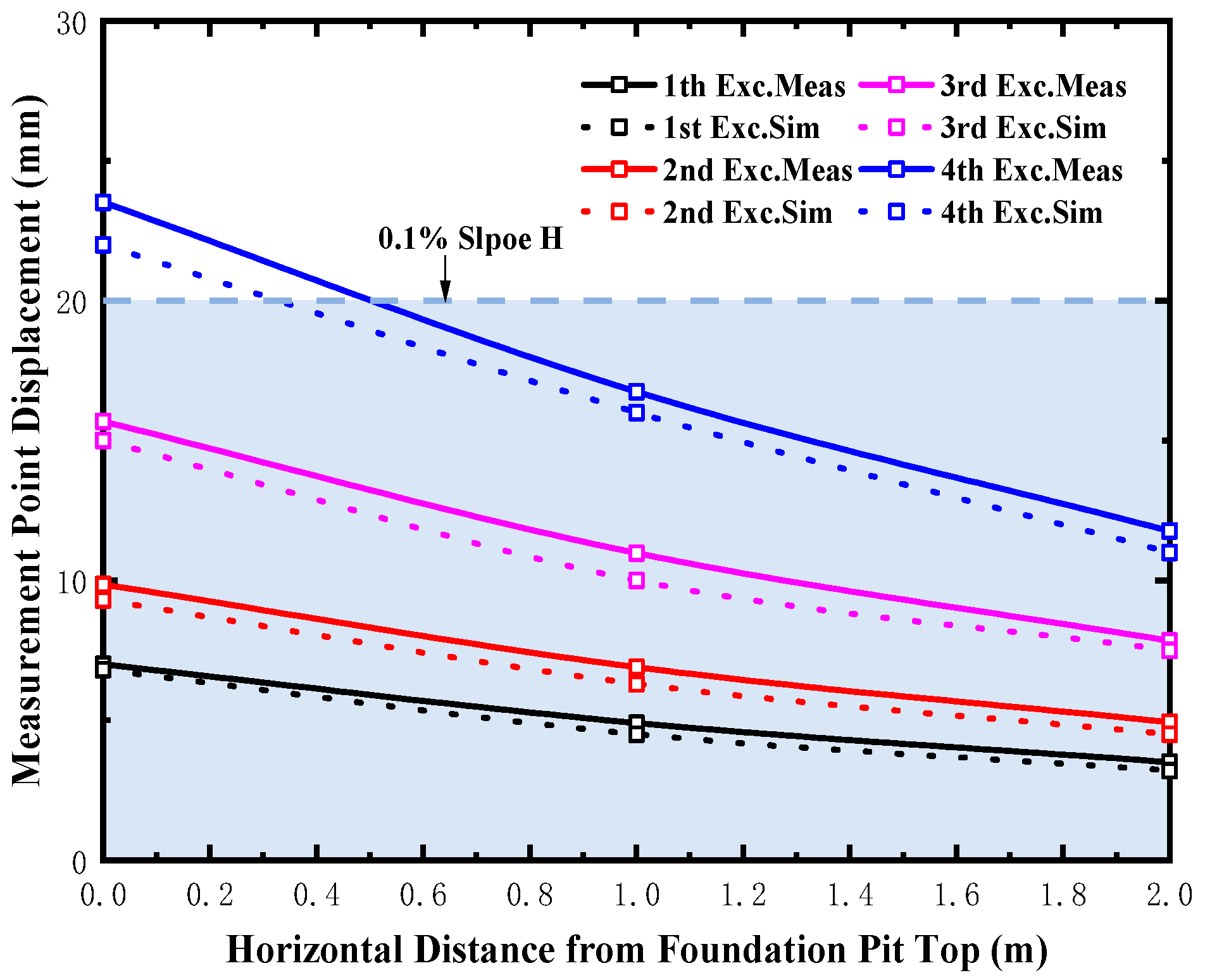
By analyzing the vertical displacement of the slope soil at positions 0~14 m from the crest, it was found that the numerical simulation results align well with the monitoring data. Figure 14 shows that defining the slope height H as the distance from the crest to the excavation bottom, increased excavation depth induces heave near the crest and settlement farther away. A displacement inflection point occurs at a distance Xt from the crest, marking the transition from heave to settlement. According to this study, for a water-rich sandy foundation pit undergoing staged excavation, the critical disturbance is observed when the ratio H/Xt ranges between 0.4 and 0.6.
Figure 14.
Calculated vs. Measured Displacement of slope crest.
5.1.2. Excavation Surface Deformation Pattern
As shown in Figure 15, the study reveals that after foundation pit excavation, the surrounding soil exhibits an upward heave trend, with noticeable vertical uplift at the secondary platform surface. The uplift displacement increased from 7 mm during the first excavation to 23 mm after the fourth excavation. The maximum uplift displacement δhm, relative to the slope height H, is approximately 0.1%H.
Figure 15.
Calculated vs. Measured Displacement of foundation pit surface.
5.1.3. Retaining Structure Deformation Behavior
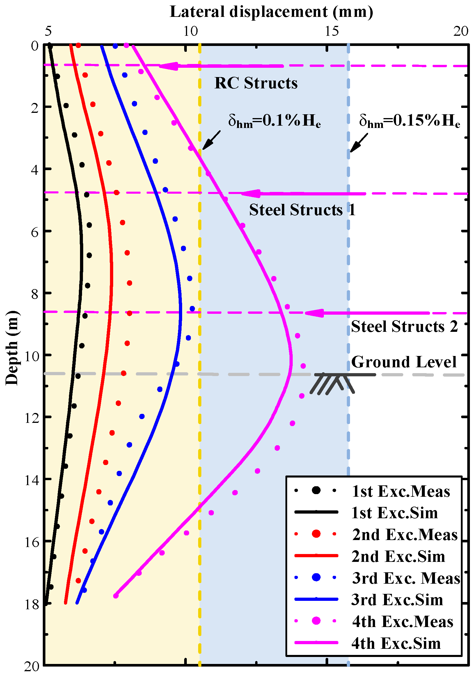
As shown in Figure 16, with the layered excavation of the foundation pit, the bending deformation of the retaining piles gradually increases, and the final maximum deformation reaches δhm = 14.7 mm. The ratio of δhm to the slope height He is 0.14%, which is smaller than the 0.2% threshold for maximum deformation. The maximum deformation occurs at the lower side of the pile base, and the depth at which the maximum displacement occurs increases with the excavation depth.
Figure 16.
Calculated vs. Measured Displacement of retaining structure.
5.1.4. Strut Force Variation and Quantification
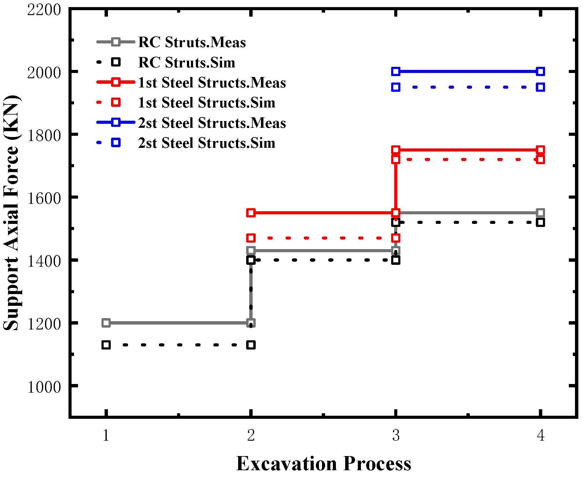
As shown in Figure 17, the study indicates that the axial force in the foundation pit supports gradually increases with excavation. Upon excavation completion, the axial force of the concrete support is the lowest at 1550 kN, representing a 19% increase from the initial value. The axial force of the second steel support on the lower side of the foundation pit reaches a maximum of 2000 kN. This result aligns well with the lateral deformation trend of the retaining piles, demonstrating good consistency.
Figure 17.
Numerical and Measured Support Axial Force during layered excavation.
5.2. Excavation Behavior and Failure Prediction Under Extreme Rainfall
This study examines the displacement and structural response of the foundation pit slope and supports when the groundwater level outside the water-stop curtain rises incrementally by 3 m from the initial level of 13.2 m (with the pit bottom elevation set at 0 m) after excavation reaches the excavation bottom. Notably, field monitoring after actual rainfall recorded a maximum groundwater rise of 2 m; therefore, this study utilizes numerical simulation to predict the potential effects of a 3 m groundwater rise.
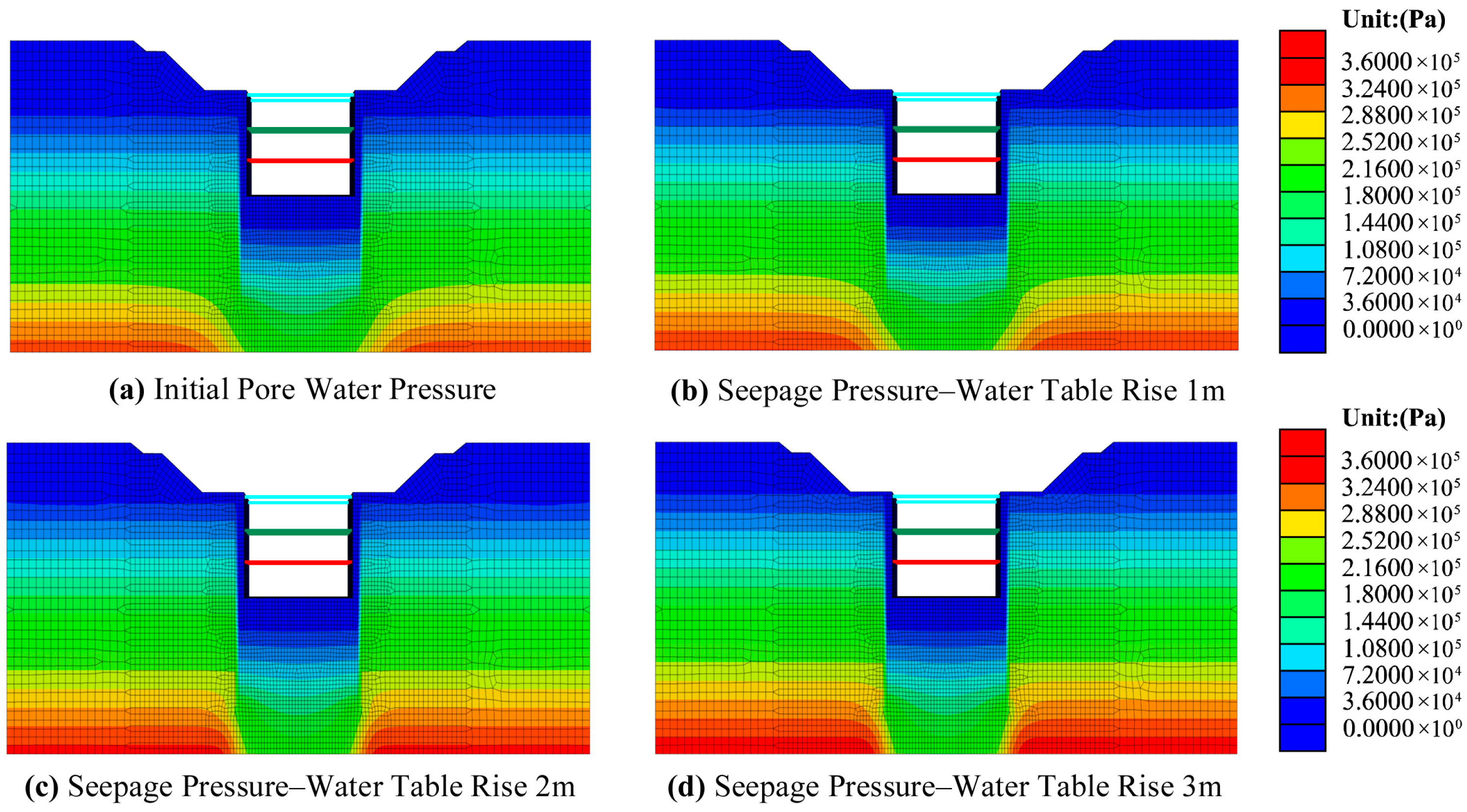
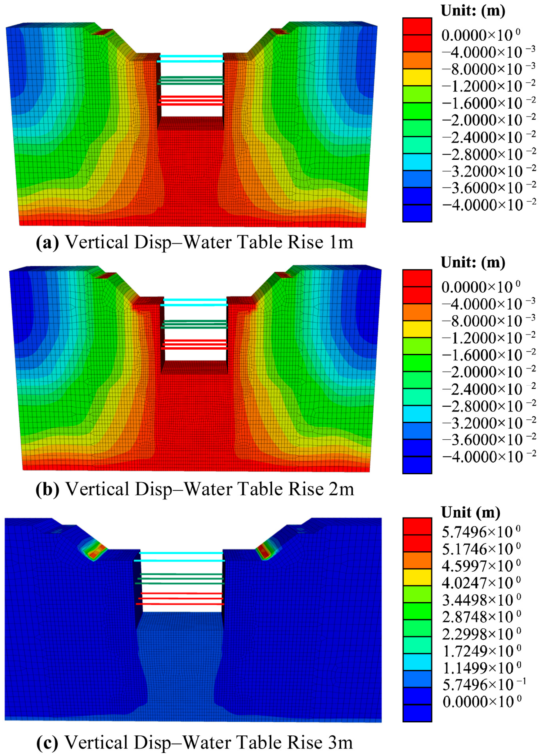
As shown in Figure 18 and Figure 19, numerical simulation results indicate that as the groundwater level rises, soil displacement and slope settlement increase, raising the risk of slope failure. As the groundwater level rises, increased soil saturation weakens matric suction, reducing soil strength. When the active earth pressure in the foundation pit exceeds the passive resistance, failure occurs [32,43,44].
Figure 18.
Seepage Contour Map for groundwater level rise of 0~3 m, (a) 0 m, (b) 1 m, (c) 2 m, (d) 3 m.
Figure 19.
Displacement for Groundwater Level Rise of 1~3 m (a), 1 m, (b) 2 m, (c) 3 m.
Figure 19c shows that when the groundwater level reaches 3 m, slope failure occurs at the toe of the secondary slope. Based on the research findings of this project, we recommend setting the warning threshold for groundwater level rise in deep foundation pit engineering in Beijing at 15%H.
5.2.1. Ground Surface Uplift–Subsidence Transition
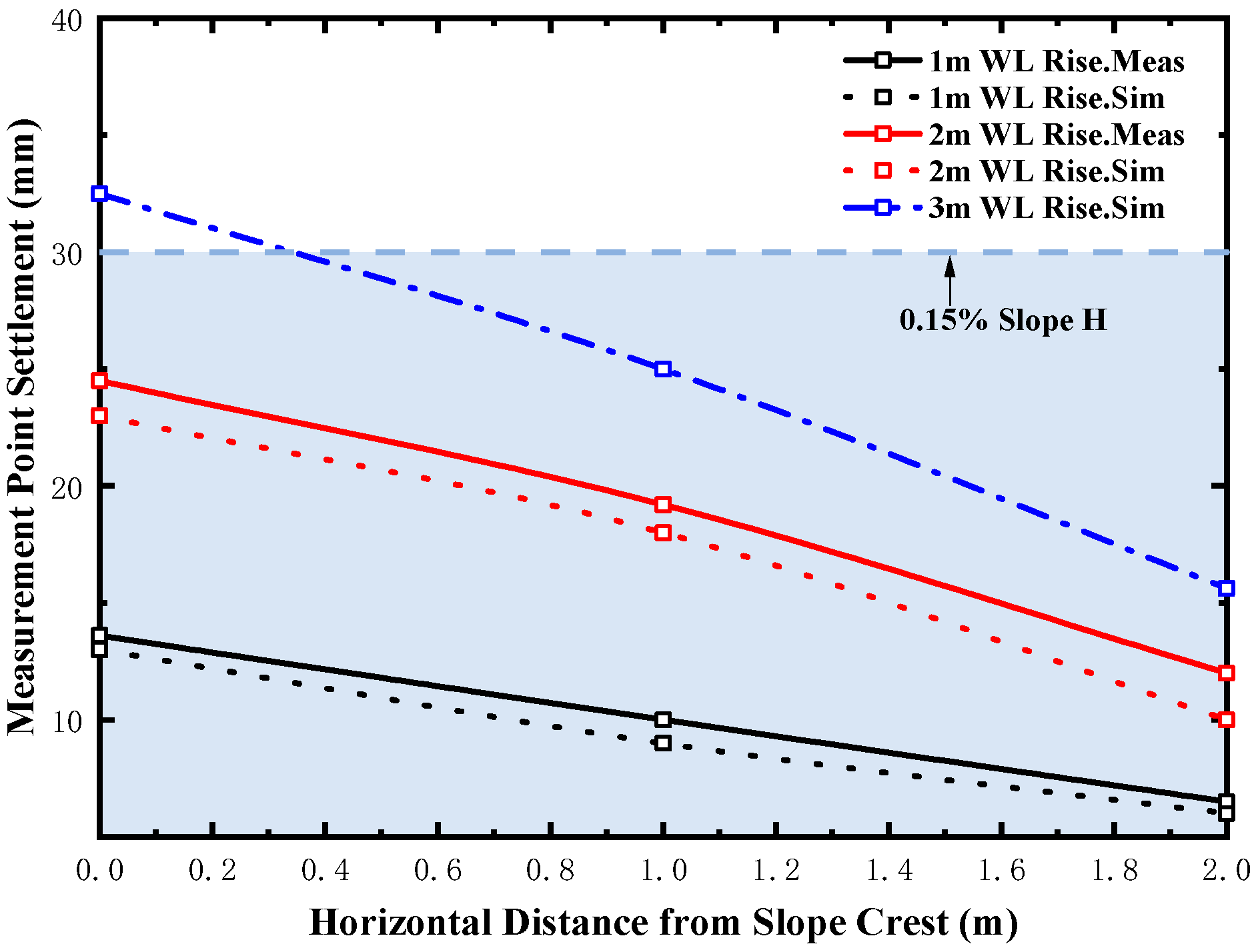
As shown in Figure 20, groundwater level rise induces settlement at the slope crest, with settlement magnitude decreasing as the distance increases. The rate of decrease gradually stabilizes. When the groundwater level rises by 3 m, the maximum settlement at the slope crest reaches 41.5 mm, approximately 0.2%H, where H represents the height from the slope crest to the foundation pit bottom.
Figure 20.
Calculated vs. Measured Displacement of slope crest under water table rise.
This study attributes the settlement to the groundwater rise, which increases soil saturation, reduces the contribution of matric suction to soil strength [12], and decreases the effective stress in the soil.
5.2.2. Excavation Surface Deformation Pattern
As shown in Figure 21, settlement at the top of the foundation pit increases with rising groundwater levels. The settlement magnitude gradually decreases with increasing distance from the pit. When the groundwater level rises by 1~2 m, surface settlement reaches 13.6 mm and 24.5 mm, respectively, representing an 80% increase. Numerical simulations predict that a 3 m groundwater rise will result in a settlement of 32.5 mm, marking a further 30% increase compared to the 2 m level. The findings indicate that when the groundwater level rises by 3 m, the settlement increment at the pit surface approaches 0.15%H.
Figure 21.
Calculated vs. Measured Displacement of excavation surface under water table rise.
5.2.3. Retaining Structure Deformation Behavior
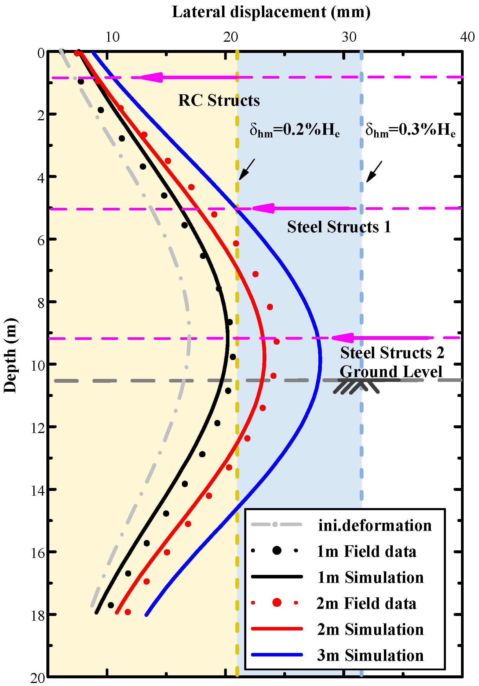
As shown in Figure 22, results indicate that the displacement of the retaining piles progressively increases with the rise of the groundwater level. When the groundwater level rises to 2 m, the maximum displacement of the retaining piles, δhm, reaches 24.9 mm, with a δhm/He ratio of 0.24%, which is consistent with the range of 0.2% to 0.5% reported by Ou et al. [45]. Numerical simulations predict that when the groundwater level rises to 3 m, δhm will reach 28 mm. Moreover, at a groundwater level of 3 m, the maximum displacement occurs near the bottom of the excavation, with δhm increasing by 90% compared to the non-rainfall condition. These findings align well with existing research results [33].
Figure 22.
Calculated vs. Measured displacement of the retaining structure under water table rise.
5.2.4. Strut Force Variation and Redundancy
As shown in Figure 23, the study indicates that the axial force in the foundation pit supports increases significantly with the rise in groundwater level, with a maximum increase of 16%. Numerical simulation results show that when the groundwater level rises by 3 m, the axial force of the concrete support increases from 1550 kN to 1800 kN, a 16% increase; the axial force of the second steel support increases from 2180 kN to 2500 kN, a 15% increase; and the first steel support experiences the smallest increase, rising from 1980 kN to 2200 kN, an 11% increase.
Figure 23.
Numerical vs. Measured Support Axial Force under water table rise.
6. Discussion
6.1. Excavation Settlement
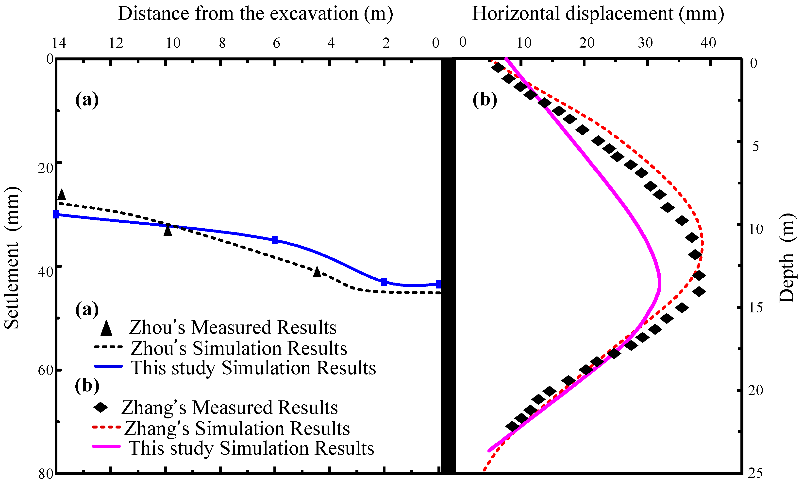
Analysis of this study reveals that the rise in groundwater level due to rainfall is a critical factor triggering excavation deformation. A comparison with a numerical case study of a multi-layered soil excavation with a similar depth of 14 m [21] shows that the maximum settlement at the excavation center falls within the range of 35–40 mm in both cases, and the settlement values decrease gradually from the center towards the periphery (Figure 24a). This result confirms that the coupled hydro-mechanical simulation is a viable method for excavation analysis.
Figure 24.
Comparison results numerical simulations and two published case records. (a) Zhou’s Results and the Present Study. (b) Zhang’s Results and the Present Study.
6.2. Impact of Rainfall on Supporting Structures
Rainfall has a pronounced effect on the lateral displacement of support piles, potentially increasing it by more than 50%. This result concurs with that reported from another excavation case in clay. The maximum lateral displacement of the retaining piles is typically observed at two-thirds of the pile depth, rather than at the top, a pattern which agrees with existing literature [33] (Figure 24b). Therefore, rational bracing design is an effective measure to mitigate the deformation of supporting structures under rainstorms [8]. Previous studies also suggest that the soil-nailing method can effectively control lateral excavation displacement [46]. In addition, scientific methods for testing the bearing capacity of supporting piles can benefit from the adoption of emerging technologies [47].
6.3. Mechanisms of Rainfall-Induced Excavation Response
Several mechanisms explain the increased excavation deformation and supporting structure forces. Under extreme rainfall conditions, fine particle migration in sandy soils reduces the soil permeability and increases pore water pressure, leading to a significant increase in soil displacement. This phenomenon has also been observed in studies on rainfall-induced slope failures [14]. Simultaneously, the reduction in soil matric suction due to rainfall infiltration makes excavations more prone to failure [34].
6.4. Engineering Application
Given the low cohesion and high sensitivity of the water-rich sandy stratum in this case, the proposed 15%H critical water level rise offers greater conservatism when applied to clay or gravelly soil sites [42]. For the foundation pit with larger width, the safety index needs to be further conservatively estimated. This study’s steady-state seepage-based approach is applicable to regions with stable or slowly varying water tables; for areas experiencing seasonal drought-rainfall cycles, transient coupled analysis is necessary to establish appropriate thresholds.
7. Conclusions
This study investigates the behavior of a Beijing excavation under a rare typhoon rainfall by integrating field monitoring with FLAC3D coupled simulations. The work examines the patterns of surface settlement, structural deformation, and internal forces, thereby proposing a safety threshold for hazard prevention. As evidenced by favorable comparisons with prior studies, the presented findings are reliable. The specific results are as follows:
- (1)
- This study quantitatively evaluates foundation pit deformation. During staged excavation, the ground surface at the slope crest exhibits an uplift near the excavation and settlement farther away, with a critical transition occurring within the range of Xt/H = 0.4~0.6. The findings also indicate that after excavation, the maximum uplift at the pit surface is approximately 0.1%H. When the groundwater level rises by 3 m (15%H), the maximum settlement at the slope crest reaches 0.2%H, while the maximum settlement at the pit surface approaches 0.15%H.
- (2)
- During excavation, the maximum deflection of the retaining piles δhm is approximately 0.14% of He, with the greatest lateral deformation occurring in the lower portion of the retaining pile. When the groundwater level rises, support axial forces increase by up to 16% and the maximum lateral displacement δhm of the retaining piles increases by 90%, with the largest displacement observed near the excavation bottom.
- (3)
- For foundation pits in high rainfall risk areas, the support system should incorporate a 20% safety margin, and the design should include reinforcement measures to mitigate the significant increase in lateral deflection.
- (4)
- This study used numerical simulations to predict a critical water rise height of 15%H in water-rich sand excavations, offering guidance for rain-related reinforcement in sandy soils. For excavations in different soil types, the critical hazardous height may vary.
- (5)
- In the study of pit seepage problems, it is crucial to select a constitutive model that more accurately reflects the loading and unloading processes of the soil. This paper simplifies the problem through a combination of field monitoring and numerical simulation. The Mohr-Coulomb model served as a pragmatic choice for this study due to the difficulty in determining accurate soil parameters during rainstorms. While its limitations are recognized, they are offset by its operational simplicity under current constraints. We advocate for future model refinement using the Hardening Soil (HS) or HS-Small model when a richer set of high-quality geotechnical parameters becomes available.
Author Contributions
Conceptualization, W.Z., J.L. and S.X.; methodology, W.Z. and J.L.; software, W.Z.; validation, J.L.; formal analysis, J.L.; investigation, J.L.; resources, J.L.; data curation, J.L.; writing—original draft, W.Z.; writing—review and editing, S.X.; visualization, W.Z.; supervision, J.L.; project administration, J.L.; funding acquisition, J.L. All authors have read and agreed to the published version of the manuscript.
Funding
This research was funded by Science and Technology Project of Hebei Education Department (No. CXY2023020). The financial support is greatly appreciated.
Data Availability Statement
Data will be supplied upon request.
Conflicts of Interest
The authors declare no conflicts of interest.
References
- Ripple, W.J.; Wolf, C.; Gregg, J.W.; Johan, R.; Mann, M.E.; Naomi, O.; Lenton, T.M.; Stefan, R.; Newsome, T.M.; Xu, C. The 2024 state of the climate report: Perilous times on planet Earth. BioScience 2024, 74, 812–824. [Google Scholar] [CrossRef]
- Hansen, J.; Ruedy, R.; Sato, M.; Lo, K. Global surface temperature change. Rev. Geophys. 2010, 48, RG4004. [Google Scholar] [CrossRef]
- Yuan, Y.F.; Liao, Z.; Zhou, B.Q. High-impact regional extreme events in China under intensified global warming and attribution research progress. Clim. Change Res. 2025, 21, 44–55. [Google Scholar]
- Ma, H.; Wang, F. Inventory of shallow landslides triggered by extreme precipitation in July 2023 in Beijing, China. Sci. Data 2024, 11, 1083. [Google Scholar] [CrossRef]
- Zhao, D.; Xu, H.; Li, Y.; Yu, Y.; Duan, Y.; Xu, X.; Chen, L. Locally opposite responses of the 2023 Beijing–Tianjin–Hebei extreme rainfall event to global anthropogenic warming. npj Clim. Atmos. Sci. 2024, 7, 38. [Google Scholar] [CrossRef]
- Ray, R.L.; Jacobs, J.M.; de Alba, P. Impacts of unsaturated zone soil moisture and groundwater table on slope instability. J. Geotech. Geoenviron. Eng. 2010, 136, 1448–1458. [Google Scholar] [CrossRef]
- Yang, H.Q.; Zhang, L.; Xue, J.; Zhang, J.; Li, X. Unsaturated soil slope characterization with Karhunen–Loève and polynomial chaos via Bayesian approach. Eng. Comput. 2019, 35, 337–350. [Google Scholar] [CrossRef]
- Liu, C.; Ji, F.; Zheng, G.; Liu, T.; Liu, Y. Measurement and mechanism of influences of rainfall on supporting structures of foundation pits in soft soils. Chin. J. Geotech. Eng. 2020, 42, 447–456. [Google Scholar] [CrossRef]
- Ng, C.W.W.; Zhou, C.; Chiu, C.F. Constitutive modelling of state-dependent behaviour of unsaturated soils: An overview. Acta Geotech. 2020, 15, 2705–2725. [Google Scholar] [CrossRef]
- Yang, H.Q.; Zhang, L.; Pan, Q.; Phoon, K.K.; Shen, Z. Bayesian estimation of spatially varying soil parameters with spatiotemporal monitoring data. Acta Geotech. 2021, 16, 263–278. [Google Scholar] [CrossRef]
- Wang, L.; Zhou, F.; He, M.; Liu, H. Contribution of Osmotic Suction to Suction Stress for Unsaturated Saline Clay and Its Suction Stress Characteristic Curve. J. Geotech. Geoenviron. Eng. 2025, 151, 04024143. [Google Scholar] [CrossRef]
- Liu, K.; Yin, J.H.; Chen, W.B.; Feng, W.Q.; Zhou, C. The stress–strain behaviour and critical state parameters of an unsaturated granular fill material under different suctions. Acta Geotech. 2020, 15, 3383–3398. [Google Scholar] [CrossRef]
- Tan, M.; Vanapalli, S.K. Numerical studies of foundation behavior subjected to combined loading considering hydrostatic and transient flow conditions in unsaturated soils. Int. J. Geomech. 2025, 25, 04024316. [Google Scholar] [CrossRef]
- Wang, Y.; Ye, F.; Li, Y.; Jin, L.; Xiao, Q.; Fu, W. Seepage response along with fine particle migration of a loose soil slope under rainfall infiltration. Int. J. Geomech. 2025, 25, 04024327. [Google Scholar] [CrossRef]
- Mangushev, R.A.; Nikiforova, N.S. Technological Settlements of the Surrounding Buildings during the Construction of Deep Pit Fences. Soil Mech. Found. Eng. 2023, 60, 15–21. [Google Scholar] [CrossRef]
- Liu, J.; Shi, C.; Cao, C.; Lei, M.; Wang, Z. Improved analytical method for pile response due to foundation pit excavation. Comput. Geotech. 2020, 123, 103609. [Google Scholar] [CrossRef]
- Zhang, X.; Yang, J.; Zhang, Y.; Gao, Y. Cause investigation of damages in existing building adjacent to foundation pit in construction. Eng. Fail. Anal. 2018, 83, 117–124. [Google Scholar] [CrossRef]
- Zhao, Y.L.; Cao, M.R.; Abi, E. Settlement Behavior Analysis of Adjacent Existing Buildings Induced by Foundation Pit Construction in River Basin. Buildings 2025, 15, 1991. [Google Scholar] [CrossRef]
- Lyu, H.M.; Shen, S.L.; Wu, Y.X.; Zhou, A.N. Calculation of groundwater head distribution with a close barrier during excavation dewatering in confined aquifer. Geosci. Front. 2021, 12, 791–803. [Google Scholar] [CrossRef]
- Harahap, S.E.; Ou, C.Y. Finite element analysis of time-dependent behavior in deep excavations. Comput. Geotech. 2020, 119, 103300. [Google Scholar] [CrossRef]
- Zhou, H.Z.; Zheng, G.; He, X.P.; Wang, E.Y.; Guo, Z.Y.; Nie, D.Q.; Ma, S.K. Numerical modelling of retaining structure displacements in multi-bench retained excavations. Acta Geotech. 2020, 15, 2691–2703. [Google Scholar] [CrossRef]
- Yuan, Y.; Xu, Y.S.; Shen, J.S.; Wang, B.Z.F. Hydraulic conductivity estimation by considering the existence of piles: A case study. Geomech. Eng. 2018, 14, 467–477. [Google Scholar] [CrossRef]
- Li, K.; Chen, S.; Pei, R.; Chen, J. Theoretical prediction study on drawdown and surface settlement induced by dewatering and excavation in unconfined aquifers. Comput. Geotech. 2025, 179, 107041. [Google Scholar] [CrossRef]
- Xue, X.L.; Sun, H.Y.; Zeng, C.F.; Chen, H.B.; Zheng, G.; Xu, C.J.; Han, L. Why pile-supported building settled continuously after water level was stabilized during dewatering: Clues from interaction between pile and multi aquifers. J. Hydrol. 2024, 638, 131539. [Google Scholar] [CrossRef]
- Shahrokhabadi, S.; Vahedifard, F.; Ghazanfari, E.; Foroutan, M. Earth pressure profiles in unsaturated soils under transient flow. Eng. Geol. 2019, 260, 105218. [Google Scholar] [CrossRef]
- Huang, C.; Wang, X.; Zhang, M.; Zhou, H.; Liang, Y. Supporting characteristics of soldier piles for foundation pits under rainfall infiltration. Adv. Civ. Eng. 2019, 2019, 1053576. [Google Scholar] [CrossRef]
- Wang, Y.; Zhang, Y.; Li, M.; Qi, Y.; Ma, T. A numerical investigation of the deformation mechanism of a large metro station foundation pit under the influence of hydromechanical processes. Geofluids 2021, 2021, 5536137. [Google Scholar] [CrossRef]
- Dong, H.; Huang, R.; Gao, Q.F. Rainfall infiltration performance and its relation to mesoscopic structural properties of a gravelly soil slope. Eng. Geol. 2017, 230, 1–10. [Google Scholar] [CrossRef]
- Soomro, M.A.; Xiong, S.; Mangi, N.; Mangnejo, D.A.; Darban, S.A. Enhancing foundation bearing capacity in waterlogged ground for sustainable building construction. Geomech. Eng. 2024, 39, 407–423. [Google Scholar] [CrossRef]
- Ng, C.W.W.; Yung, S.Y. Determination of the anisotropic shear stiffness of an unsaturated decomposed soil. Géotechnique 2008, 58, 23–35. [Google Scholar] [CrossRef]
- Zhai, Q.; Rahardjo, H.; Satyanaga, A.; Dai, G. Estimation of unsaturated shear strength from soil–water characteristic curve. Acta Geotech. 2019, 14, 1977–1990. [Google Scholar] [CrossRef]
- Hoy, M.; Doan, C.B.; Horpibulsuk, S.; Suddeepong, A.; Udomchai, A.; Buritatum, A.; Arulrajah, A. Investigation of a large-scale waste dump failure at the Mae Moh mine in Thailand. Eng. Geol. 2024, 329, 107400. [Google Scholar] [CrossRef]
- Zhang, X.Q.; Li, M.G.; Chen, J.J. Hydro-mechanical analysis of a braced foundation pit affected by rainfall and excavation in unsaturated soils. Acta Geotech. 2022, 17, 5675–5690. [Google Scholar] [CrossRef]
- Wang, D.; Wang, G.F.; Lu, L.H.; Cao, Z.L.; Xu, Q.W. Suitable constitutive model of pit in thick alluvial clay along Huanghe River. Civ. Environ. Eng. 2019, 41, 36–47. [Google Scholar] [CrossRef]
- Ye, G.L.; Ye, B. Investigation of the overconsolidation and structural behavior of Shanghai clays by element testing and constitutive modeling. Undergr. Space 2016, 1, 62–77. [Google Scholar] [CrossRef]
- Hamidi, A.; Tourchi, S.; Kardooni, F. A critical state based thermo-elasto-plastic constitutive model for structured clays. J. Rock Mech. Geotech. Eng. 2017, 9, 1094–1103. [Google Scholar] [CrossRef]
- Zhang, W. Influence of groundwater drawdown on excavation responses—A case history in Bukit Timah granitic residual soils. J. Rock Mech. Geotech. Eng. 2018, 10, 856–864. [Google Scholar] [CrossRef]
- Kouretzis, G.P.; Sheng, D.; Wang, D. Numerical simulation of cone penetration testing using a new critical state constitutive model for sand. Comput. Geotech. 2014, 56, 50–60. [Google Scholar] [CrossRef]
- Huang, A.J.; Wang, D.Y.; Wang, Z.X. Rebound effects of running tunnels underneath an excavation. Tunn. Undergr. Space Technol. 2006, 21, 399. [Google Scholar] [CrossRef]
- Xu, Z.H.; Wang, W.D. Selection of soil constitutive models for numerical analysis of deep excavations in close proximity to sensitive properties. Rock Soil Mech. 2010, 31, 258–264. [Google Scholar] [CrossRef]
- Karthik, A.V.R.; Manideep, R.; Chavda, J.T. Sensitivity analysis of slope stability using finite element method. Innov. Infrastruct. Solut. 2022, 7, 184. [Google Scholar] [CrossRef]
- Wang, X.; Xiao, J.; Zhang, T.; Lin, Y. Effect analysis of supporting structure and surface settlement on deep foundation pit by rainstorm: A case study in Zhengzhou. Water 2022, 14, 3654. [Google Scholar] [CrossRef]
- Han, M.; Chen, X.; Jia, J. Analytical solution for displacement-dependent 3D earth pressure on flexible walls of foundation pits in layered cohesive soil. Acta Geotech. 2024, 19, 5249–5275. [Google Scholar] [CrossRef]
- Liu, W.; Tong, L.; Li, H.; Wang, Z.; Sun, Y.; Gu, W. Multi-parameter intelligent inverse analysis of a deep excavation considering path-dependent behavior of soils. Comput. Geotech. 2024, 174, 106597. [Google Scholar] [CrossRef]
- Ou, C.Y.; Hsieh, P.G.; Chiou, D.C. Characteristics of ground surface settlement during excavation. Can. Geotech. J. 1993, 30, 758–767. [Google Scholar] [CrossRef]
- Alkhdour, A.; Yasin, A.A.; Tiutkin, O. Rational design solutions for deep excavations using soil nail wall systems. Min. Miner. Deposits 2023, 17, 110–118. [Google Scholar] [CrossRef]
- Lukpanov, R.E.; Yenkebayev, S.B.; Tsigulyov, D.V. Assessment of the bearing capacity of piles in soil, determined by static and dynamic load tests. Eng. J. Satbayev Univ. 2021, 143, 252–260. [Google Scholar] [CrossRef]
Disclaimer/Publisher’s Note: The statements, opinions and data contained in all publications are solely those of the individual author(s) and contributor(s) and not of MDPI and/or the editor(s). MDPI and/or the editor(s) disclaim responsibility for any injury to people or property resulting from any ideas, methods, instructions or products referred to in the content. |
© 2025 by the authors. Licensee MDPI, Basel, Switzerland. This article is an open access article distributed under the terms and conditions of the Creative Commons Attribution (CC BY) license (https://creativecommons.org/licenses/by/4.0/).