2. Materials and Methods
For processing Portland cement, a vortex mill model 297 was used (Regionmettrans Co., Nizhny Novgorod, Russia); the methodology and operating modes of the vortex mill are presented in work [
15]. Cylindrical ferromagnetic bodies with the following characteristics were used for processing mineral powders: length L = 21 mm, diameter D = 2.5 mm, weight of 0.8 g, material-steel. To perform mathematical calculations, the ANSYS software package version 2020 was used.
The main advantages of the vortex mill are low specific energy consumption: the energy consumption of the vortex mill used in operation is 5 kWh, the volume of the working chamber is 3485 cm3. In addition, the use of metal cylinders as grinding media does not lead to wear of the working chamber of the device.
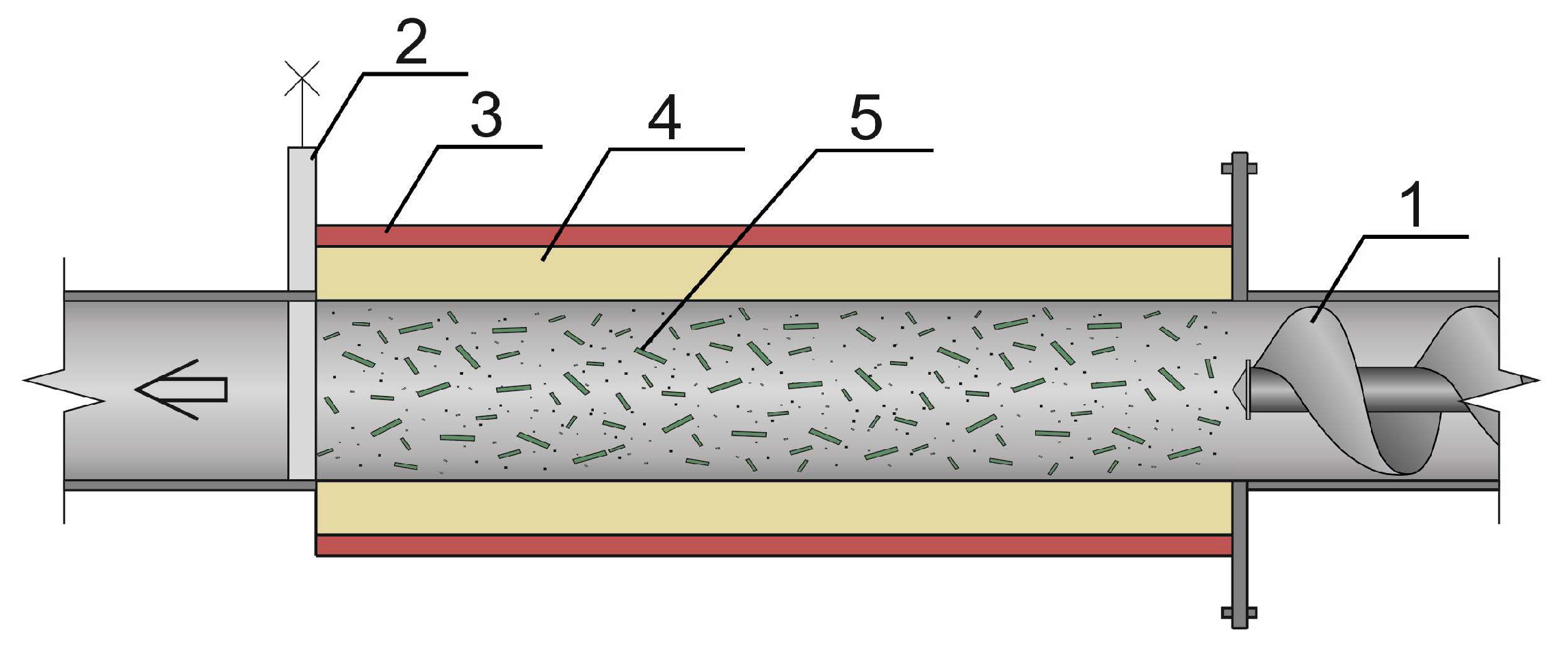
The diagram of a vortex mill is shown in
Figure 1. Grinding in a vortex mill is based on the physical principle of a rotating electromagnetic field that rotates metal (steel) ferromagnetic bodies. These grinding bodies, in the process of their movement, affect the crushed material.
Portland cement CEM I 42.5 N from “Novotroitsk Cement Plant” OJSC (Novotroitsk, Russia), compliant with EN 197-1 [
26], was used as the mineral binder. It had the following mineralogical composition: C
3S—64–65%, C
2S—11–13%, C
3A—5–6%, C
4AF—14–15%, with an initial specific surface area of 375.5 m
2/kg.
The specific surface area and average particle size were estimated using a PSH-9 dispersion analysis device (New technology Co., Moscow, Russia), the principle of which is based on the Kozeny-Carman method. The gas permeability of the powder layer is determined by the duration of air filtration through it under a fixed initial and final vacuum in the working volume of the device. To calculate the specific surface area and average particle size, the specific gravity (density) of the powder material, the mass of the powder, and the height of its layer in the cuvette are used. The PSH-9 device has a measurement range for specific surface area from 200 to 60,000 cm2/g, particle size from 0.1 to 250 μm, and a measurement error of ±1.5%.
The particle size distribution and average particle size (davg) of the studied mineral powders were determined using a Partica LA-950V2 laser particle analyzer from “Horiba (Kyoto, Japan)”. During the measurement, ultrasonic treatment was applied for particle deagglomeration. The medium in which the particle distribution was determined was ethyl alcohol33. The amount of powder for one test was 0.5–1.0 g, and the amount of dispersing liquid was 50–75 mL. The analyzer’s principle of operation is based on laser diffraction, which posits that the angle of light scattered by a particle depends on its size. Large particles scatter light at small angles, and conversely, small particles scatter it at large angles. The intensities and angles of the scattered light, obtained from a collection of suspended particles, are converted into particle size distribution. The analyzer can determine particle sizes in the range from 10 nm to 3 mm.
Optical studies of the obtained cement stone samples were carried out using a Philips XL-30 scanning electron microscope (Philips, Amsterdam, The Netherlands).
The specific surface area of the cement stone fracture was determined by the BET method based on nitrogen adsorption under the following sample degassing conditions: time—3 h; temperature—150 °C; vacuum—2 Pa.
3. Results
To describe the motion of ferromagnetic bodies, equations for the position coordinates or velocity of the particles and their angular rotation speed are used. As a first approximation, we will neglect the cylindrical shape of the ferromagnetic bodies and write the equation of motion for a spherical ferromagnetic particle under the action of a magnetic force
, without considering aerodynamic resistance:
where
—is the velocity of the ferromagnetic body;
is the mass of the ferromagnetic body.
The expression for the magnetic force in a general form is given as [
27,
28]:
where
—is the volume of the ferromagnetic body, m
3;
—is the specific magnetic susceptibility of the ferromagnetic body’s substance, m
3/kg;
B is the magnetic field induction, T; grad
B is the gradient of the magnetic field induction. In a general case, the motion of ferromagnetic bodies occurs in a magnetic field that is non-uniform in radius and angle (3). Assuming that only the radial non-uniformity of the magnetic field induction is considered, we write the vector Equation (1) as:
By changing the variable from time
t to the independent variable radius
r, Equation (3) can be written as a single equation:
The solution of (4) gives the dependence of the particle velocity
on the radius
r:
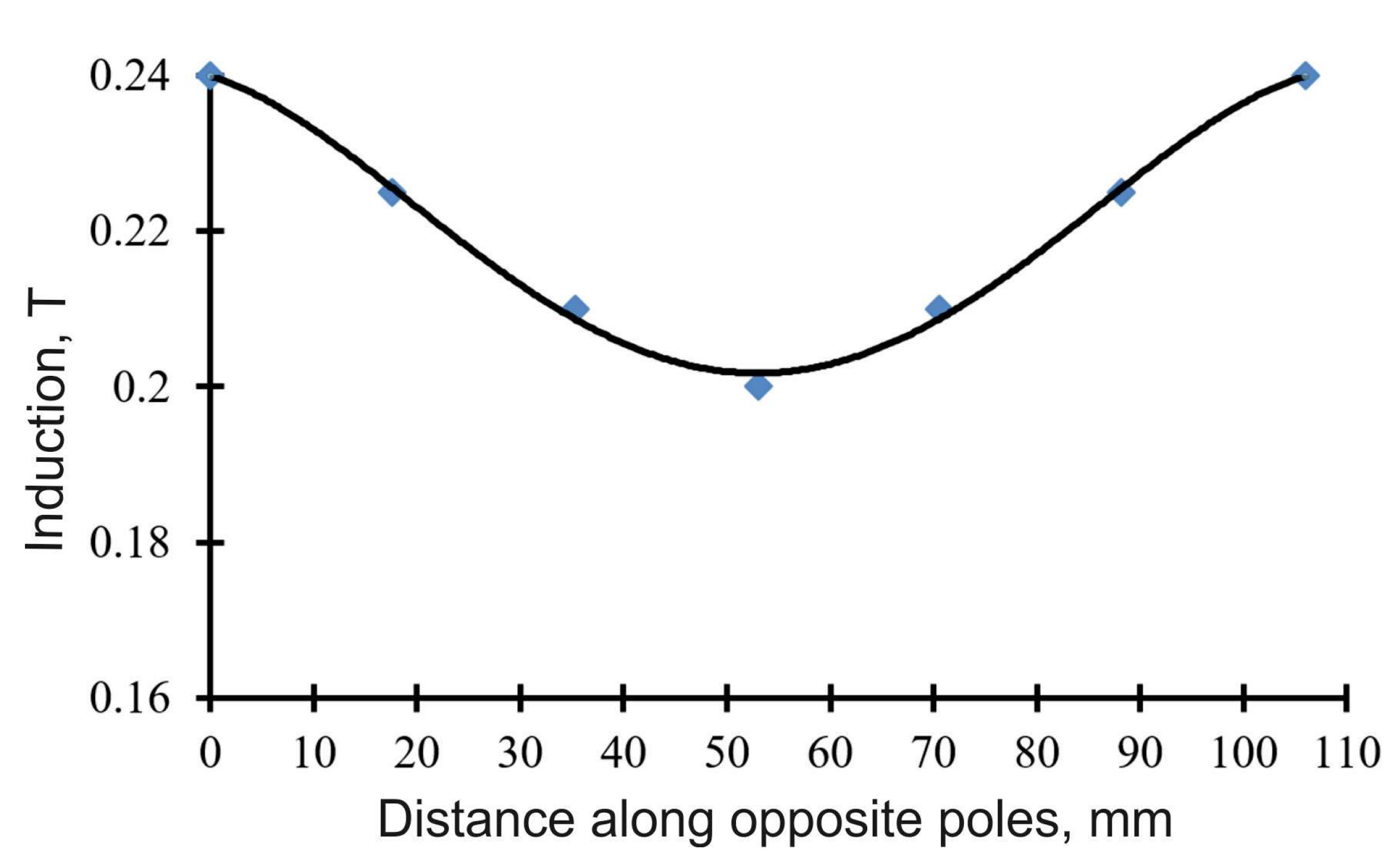
To calculate the velocity of the ferromagnetic bodies using Formula (5), we determine the gradient of the magnetic field induction from the experimental curve (
Figure 2). The decrease in magnetic induction from the walls to the center of the chamber can be represented as a linear function. Then the rate of change in the magnetic field induction along the coordinate
r can be calculated:
where
—are the values of magnetic induction at the center of the working chamber and at its walls. The specific magnetic susceptibility
is represented as:
where χ—is the magnetic susceptibility of the ferromagnetic body’s substance;
is the density of the ferromagnetic body’s substance, kg/m
3.
The magnetic susceptibility of the substance χ is calculated as the ratio of the substance’s magnetization
Js to the magnetic field strength
H:
The magnetic field strength is related to the magnetic induction by the formula:
For a magnetic induction value of B = 0.22 T, the field strength will be H = 1.75·10
5 A/m. Finally, the value of the specific magnetic susceptibility, considering the presented characteristics, will be
. The magnetic field force acting on the ferromagnetic body will be equal to:
In work [
2], this characteristic was not evaluated, but the maximum impact force of a ferromagnetic body was determined using barium titanate sensors. According to the data from that study, the impact force of a ferromagnetic body varies in the range of 20–90 H, depending on the size ratio of the ferromagnetic bodies and their quantity in the working chamber of the vortex mill.
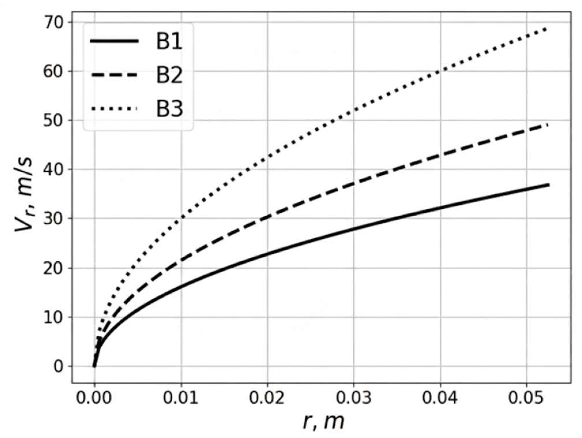
Figure 3 shows the velocity distribution of a ferromagnetic particle along the radius for different gradients of magnetic field induction. Variant B2 corresponds to the distribution of magnetic field induction B shown in
Figure 2, which was obtained experimentally. Variants B1 and B3 correspond to values of
T and
T.
The results presented in
Figure 3 demonstrate that the velocities of ferromagnetic bodies reach values of 50 m/s closer to the edge of the vortex mill’s working chamber. The time for particles to travel from the center of the working chamber to the wall and back is approximately 0.005 s, and the particle velocity during impact with the chamber wall can reach 50 m/s. It should be noted that the obtained velocity values were calculated without considering the influence of the medium’s aerodynamic resistance on the motion of the ferromagnetic particles. In the case of their movement in an unfilled chamber, the resistance of the air medium is generally negligible compared to the magnetic force. For a chamber filled with the processed material, such resistance may be significant.
The change in the velocity of a ferromagnetic body (FB) depending on its location in the chamber is non-linear: the FB’s velocity increases rapidly in the central zone of the working chamber, and then the growth rate gradually decreases. However, as it approaches the outer edge of the apparatus’s working chamber, the FB’s velocity can reach 50 m/s. The simulation established that the FB accelerates towards the working chamber wall, acquiring maximum velocity, rebounds, and moves back towards the center of the chamber. The velocity of the FB characterizes the effect of their impact on the particles of the processed material. To establish the minimum velocity sufficient for the destruction of the processed material particles, a model of a particle’s impact on an FB was developed (using the finite element method in the Ansys version 2020 software package). The problem was solved by minimizing the functional of the quadratic residual between the calculated and experimental data—the dependence of the average particle diameter on the processing duration. The results of calculating the maximum stresses at the moment of a particle’s impact with a ferromagnetic body are shown in
Figure 4, and the dependence of the maximum compressive stresses on the average particle diameter is given in
Table 1.
Based on the data in
Figure 4, the compressive strength limit Rb, of a Portland cement particle can be determined by assuming that when the diameter reaches a critical value
the particle ceases to fracture. Then the compressive strength limit is 237 MPa. Numerical experiments were conducted at different impact velocities of the ground material particles against the FB. For this, an impact velocity was set, and considering the results obtained above for the strength limit of Portland cement particles, the particle diameter was selected such that the condition of equality between the particle’s strength limit and the maximum compressive stress was met, i.e.,:
The critical diameter is the minimum particle diameter at which it does not fracture at a given velocity.
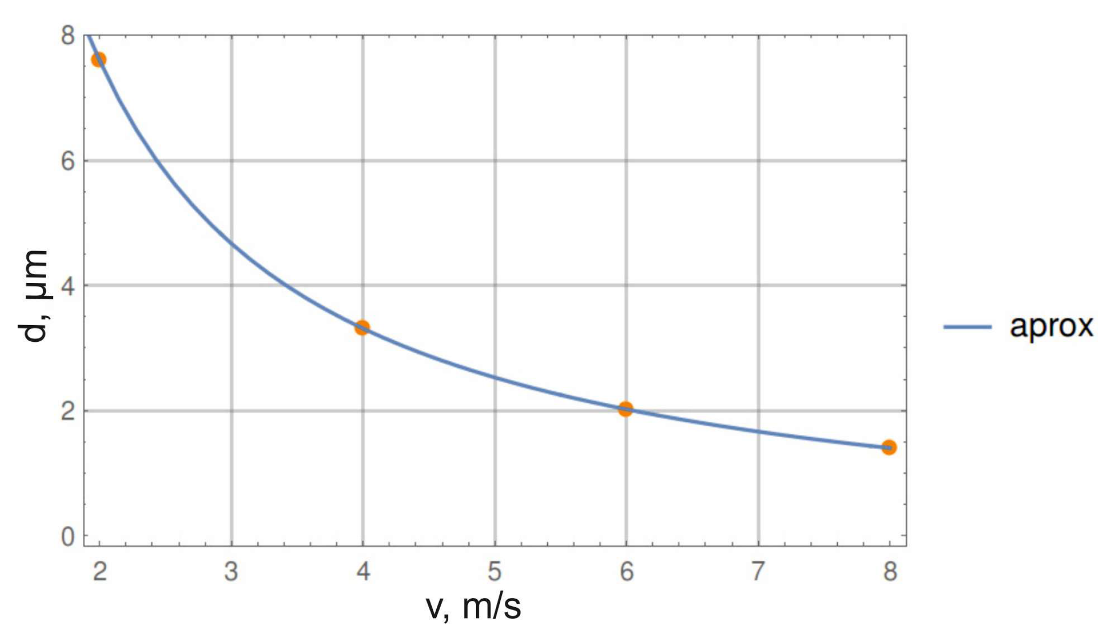
Figure 5 shows the results of these investigations.
The results obtained are well described by a function of the form:
with the following coefficient values:
a = 9.1·10
−3 μm;
b = 1.0;
c = 8.14·10
−4 μm·s/m. Consequently, the minimum diameter of a Portland cement particle that can be achieved
nm.
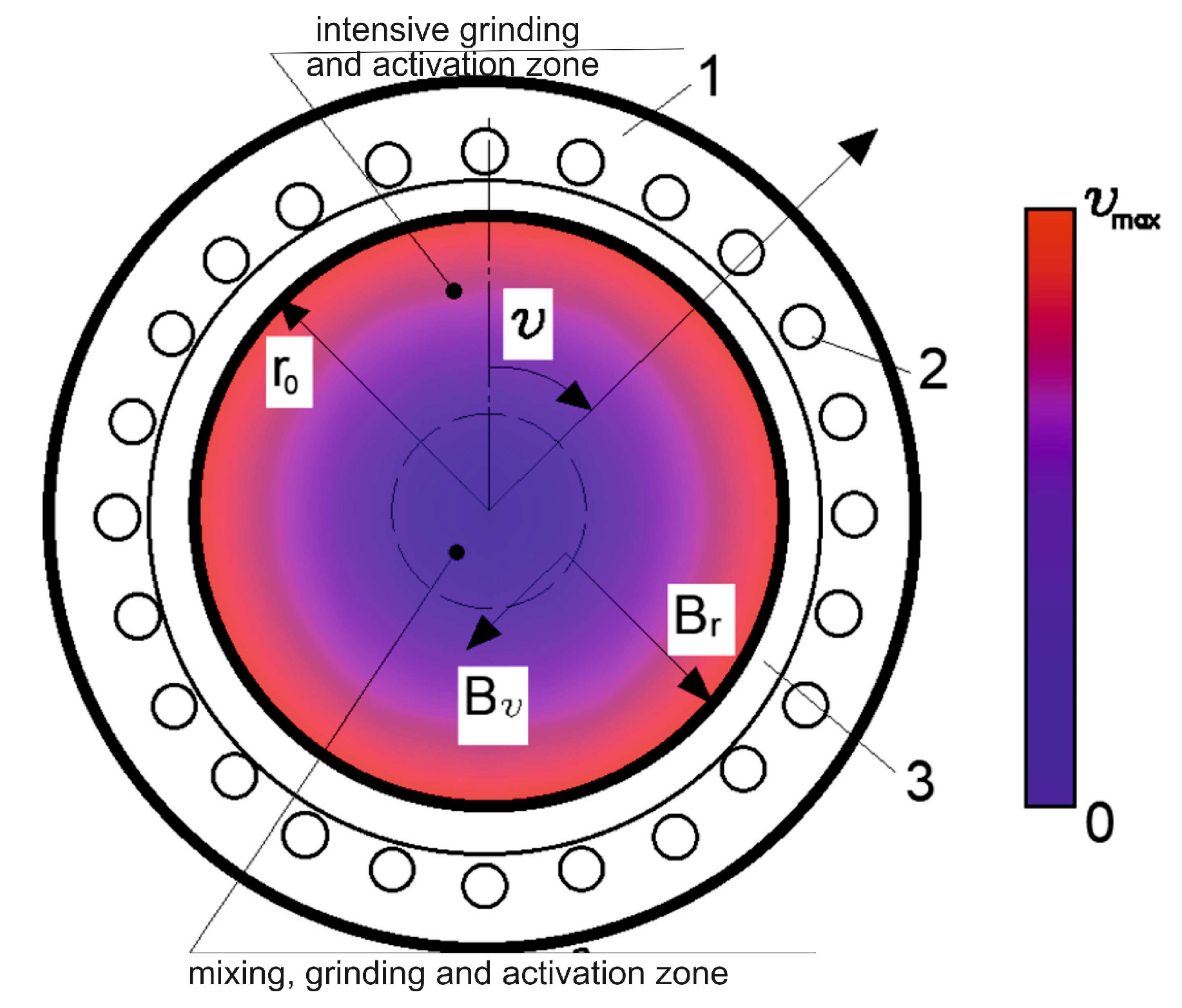
Thus, it was revealed that for the destruction of Portland cement particles, the minimum FB velocity should be 6 m/s, and considering the calculation condition—the immobility of the processed material particle—based on the velocity distribution scheme, the minimum FB velocity should be no less than 12 m/s. This result forms the basis for the zoning of the vortex mill’s working chamber (
Figure 6): (1) a zone of mixing, grinding, and particle surface activation, where the velocity range of ferromagnetic bodies is 0–12 m/s, and where the formation of the first group of ground particles with diameters greater than 1.0 μm occurs; (2) a zone of intensive grinding and particle surface activation (FB velocity range is 12–50 m/s).
Under the action of the magnetic force, the FBs move at high speed within the working volume of the vortex mill, colliding with particles of the processed material. As a result, these particles begin to move, colliding with each other, with the FBs, and with the wall of the vortex mill’s working chamber. Some of these collisions lead to the destruction (grinding) of the processed material particles. As the number of collisions increases, the number of fragmented particles grows. Furthermore, the interaction of particles with each other and their collisions with FBs lead to the transformation of the structure and properties of the surface layer of the processed material particles, which differ from their initial state [
28,
29]. This transformed substance can influence the structure formation of the building material in the initial period.
The number of collisions between all objects (processed material particles and ferromagnetic bodies) in the mill’s working chamber over a given processing period is very large. From the total set of collisions, an estimate can be made of the number of collisions that lead to the grinding of the processed material particles. For this, we consider a model of a particle splitting into
parts (
). In this case, the condition of equality of the volumes of the particle and its parts is valid:
where
is the initial particle diameter;
—is the particle diameter after processing for a duration of
. Each stage of a particle’s destruction into
parts we will call a disintegration cycle. After
disintegration cycles, the particle diameter will be:
The surface area of the resulting particles will be:
where
—is the initial surface area of the particle.
From the last equation, the number of particle disintegration cycles by time
can be determined:
The number of collisions that led to particle destruction can be estimated by the formula:
where
—is the initial number of processed material particles, equal to:
here
and
—are the mass and density of the processed material.
At several time steps
o of the apparatus’s operation, the specific surface area of the processed material
is determined by the Blaine method [
29] (
Table 2). Based on the obtained values of
, the values of
were calculated.
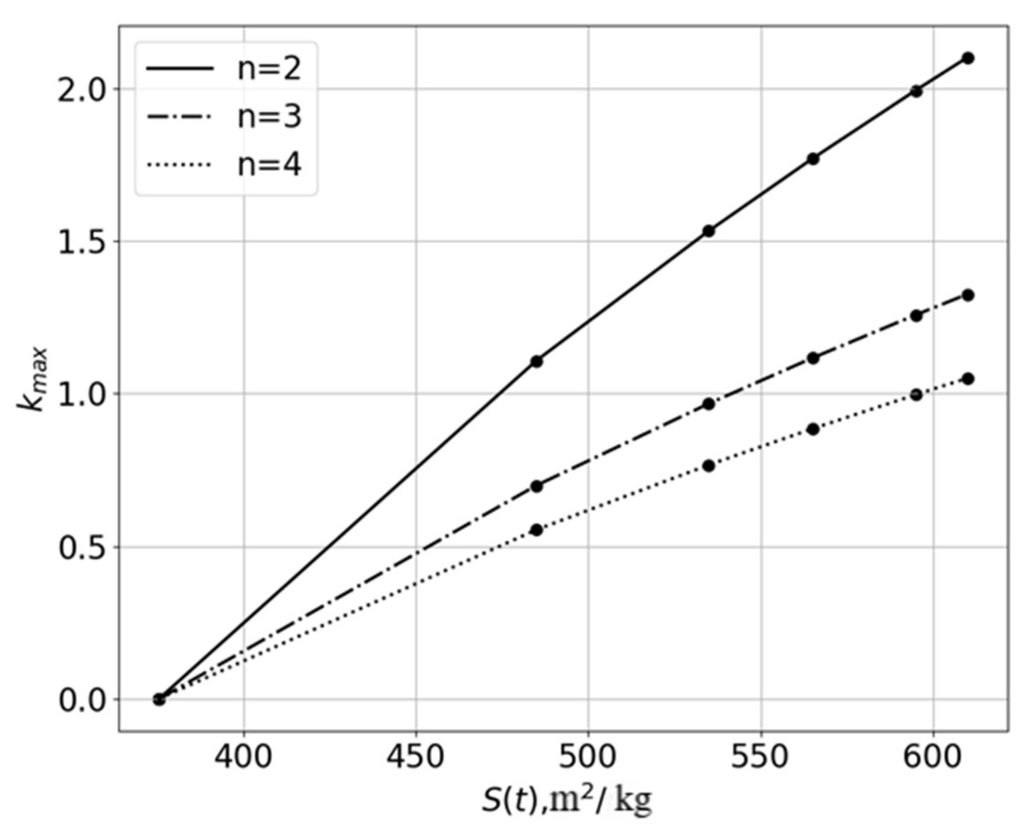
The dependence
for various values of
n is shown in
Figure 7. It can be seen that the number of disintegration cycles of Portland cement particles, calculated by Formula (18), is not an integer. This indicates that the value
calculated from experimental data characterizes the weighted average value of this quantity. Hence, the value
can be represented as:
where
is the nearest minimum integer number of disintegration cycles;
is the fraction of particles. Thus, from the data in
Figure 7 it follows that when the number of parts into which a Portland cement particle splits is
n = 2 the number of disintegration cycles slightly exceeds
2.1. From this, the fraction of Portland cement particles that disintegrated
2 times is:
and the remaining fraction of particles (10%) disintegrated more than two times.
Similarly, calculations can be made for other values of n. Naturally, as n—the number of parts into which a Portland cement particle fractures—increases, the number of its particles that break once () increases. For example, at n = 3 the fraction of particles destroyed once is , and at n = 4, it is .
Figure 8 shows the normalized
particle size distributions of Portland cement powder before processing (
t = 0) and after 8 min of processing in the vortex mill. Not only a quantitative but also a qualitative difference between the distributions is observed. The initial unimodal distribution of the processed material transforms into a bimodal one. This means that the ground particles are divided into two distinct groups with their own modes. Along with the group of larger particles, a separate group of highly ground particles appears. This character of grinding is determined by the impact force of the FBs on the Portland cement particles, which in turn depends on their velocity. From the FB velocity distribution shown in
Figure 3, it can be concluded that the highest velocities, and consequently, the greatest disintegration of some Portland cement particles, are expected in the annular zone of the working chamber located near its walls. The largest tangential gradients of magnetic field induction are also expected closer to the boundaries of the working chamber.
Figure 8 also shows a theoretical distribution obtained from the initial experimental one by applying a binary splitting model (
n = 2) of Portland cement particles over two disintegration cycles
. It is evident that such a model describes the distribution of ground particles in the first group of larger particles quite well. That is, the theoretical model of binary splitting can be quite applicable for an approximate description of the grinding process in a vortex mill. At the same time, the proposed splitting model does not allow for obtaining the second group of highly ground particles, for which the number of disintegrations is
. In addition, it should be noted that the proposed particle splitting model is based on the representation of particles as spherical. For real particles, the ratio of surface area to volume is greater than for spherical particles (
).
The correlation of the presented model of the particle size distribution of Portland cement powder is shown in
Figure 8, where the green curve (obtained according to the model) well describes the experimental distribution (red). The standard deviation was 0.74. Along with the a priori unknown number of parts after a single fracture, an important question is determining the critical diameter of Portland cement particles, below which their destruction will not occur.
The influence of the FB movement speed on the diameter of Portland cement particles at which they destruct has been determined. It has been established that at an FB speed of ~6 m/s, the critical diameter of Portland cement is ~2 μm, and ~0.19 μm at a speed of ~50 m/s. These values are consistent with the data presented in
Figure 8, where the minimum diameter of a ground Portland cement particle is ~0.1 μm. At the same time, from
Figure 8 it is clear that Portland cement particles with a diameter of ~1.0 μm correspond to the transition boundary from the group of smaller ground particles to the group of larger ones. This boundary is consistent with an FB speed of ~12 m/s. This velocity value can be used to estimate the fraction of collisions leading to particle destruction.
The number of collisions leading to the destruction of Portland cement particles is a constant value, independent of
n. Thus, according to experimental data (
Table 2 and
Figure 8),
. The calculation will be carried out only with respect to Portland cement particles (the number of FBs is not taken into account). Let us assume that all Portland cement particles are uniformly distributed in the space of the apparatus’s working chamber. In this case, the average distance between the centers of the particles will be equal to:
where
—is the volume of the working chamber.
A particle will cover this distance (neglecting the geometric dimensions of the particles) in a time equal to:
(here
is the critical velocity; it is taken as
m/s). We also assume that only a fraction of the particles,
. participate in collisions. The collision frequency will be inversely proportional to
, and the number of collisions will be proportional to the number of particles participating in collisions. Hence, the total number of collisions during the processing time
will be:
Using the obtained formula, as well as Formula (21), we determine the fraction of collisions that lead to particle destruction:
Estimates show that even at the fraction of collisions leading to particle destruction is insignificant, amounting to . With an increase in the number of colliding particles (fraction ) the efficiency of the destruction process () decreases, as the value of increases, while the number of collisions leading to particle destruction, , remains unchanged. For instance, when increases to 0.01% the collision efficiency decreases by an order of magnitude to .
The energy of destruction of material particles
can be estimated by the magnitude of the change in particle dispersion of the processed material:
where
—is the surface tension of the processed material before mechanomagnetic treatment;
—is the change in surface area during mechanomagnetic treatment. In practice, when determining E_dest, it is sufficient to determine the specific surface area of the processed mineral component using the Blaine method, and the value of
—taking into account the mass of the material
and the duration of processing in a vortex mill:
where
—is the specific surface area of the mineral component (material) according to the Blaine method;
—is the duration of processing.
According to the calculations obtained, the energy that leads to the destruction of material particles is up to 26 joules, which is about 0.01% of the total energy spent on activation.
From this, we can identify both the main functions of the FBs and the main mechanisms of destruction and activation of the processed material particles in the vortex mill. The following types of interactions are possible:
- (1)
FB—processed material particle;
- (2)
Processed material particle—processed material particle;
- (3)
Processed material particle—VLA working chamber wall;
- (4)
FB—FB;
- (5)
FB—apparatus working chamber wall.
Of the presented types of interactions, only the first three lead to the destruction and change in the surface properties of the processed material particles (particle activation). The characteristic that serves as a criterion for separating the processes of particle destruction and activation is the velocity of the FB. Thus, it can be concluded that FBs, under the action of magnetic force, move with a velocity in a wide range of values—from 0 to 50 m/s—and set the particles of the processed material in motion, causing their destruction. Based on the results obtained, the presence of two main zones of grinding for mineral components in the working chamber of the apparatus can be assumed:
- (1)
A zone of mixing, grinding, and activation of particles, in which the velocity range of the ferromagnetic bodies is 0–12 m/s, where the formation of the first group of ground particles with diameters greater than 1.0 μm occurs;
- (2)
A zone of intensive grinding and activation of particles (the velocity range of the ferromagnetic bodies is 12–50 m/s).
It should also be noted that a significant portion of collisions leads to physical processes such as heating, thermal radiation, and the transformation of the surface layer substance into an active substance [
30,
31]. As the size of the processed material particles decreases, the probability of their destruction upon collision will decrease due to their reduced mass and increased strength.
A key task for the use of the vortex mill in the real industrial sector is to optimize its efficiency in processing powder materials [
32,
33]. From the results obtained and previous research [
25,
28], let us define the main factors affecting the processing efficiency of mineral powder materials. The grinding and activation process is primarily influenced by the magnitude of the magnetic force, which is proportional to the magnetic field induction and its gradient. Both quantities are characteristics of the electromagnetic field and can be optimized by selecting the type of vortex mill and managing its parameters. The processing of powder media in a vortex mill includes two interrelated aspects:
- (1)
Mechanical aspect: setting the ferromagnetic bodies in motion and their influence on the particles of the processed material, as well as the types of interactions between ferromagnetic bodies, processed material particles, and the VLA working chamber wall. The choice of size, shape, and concentration of ferromagnetic bodies in the working chamber affects the frequency of their collisions with the processed material particles and the efficiency of their grinding and activation, and consequently, the duration of processing;
- (2)
Magnetoplastic aspect: the positive effect of the electromagnetic field on reducing the strength and deformation properties of the processed material [
25]. This effect depends on the properties of the processed material and its heating temperature, which increases during the operation of the VLA. With an increase in the magnetic susceptibility of the processed material, the processing efficiency—grinding and activation of particles—increases.
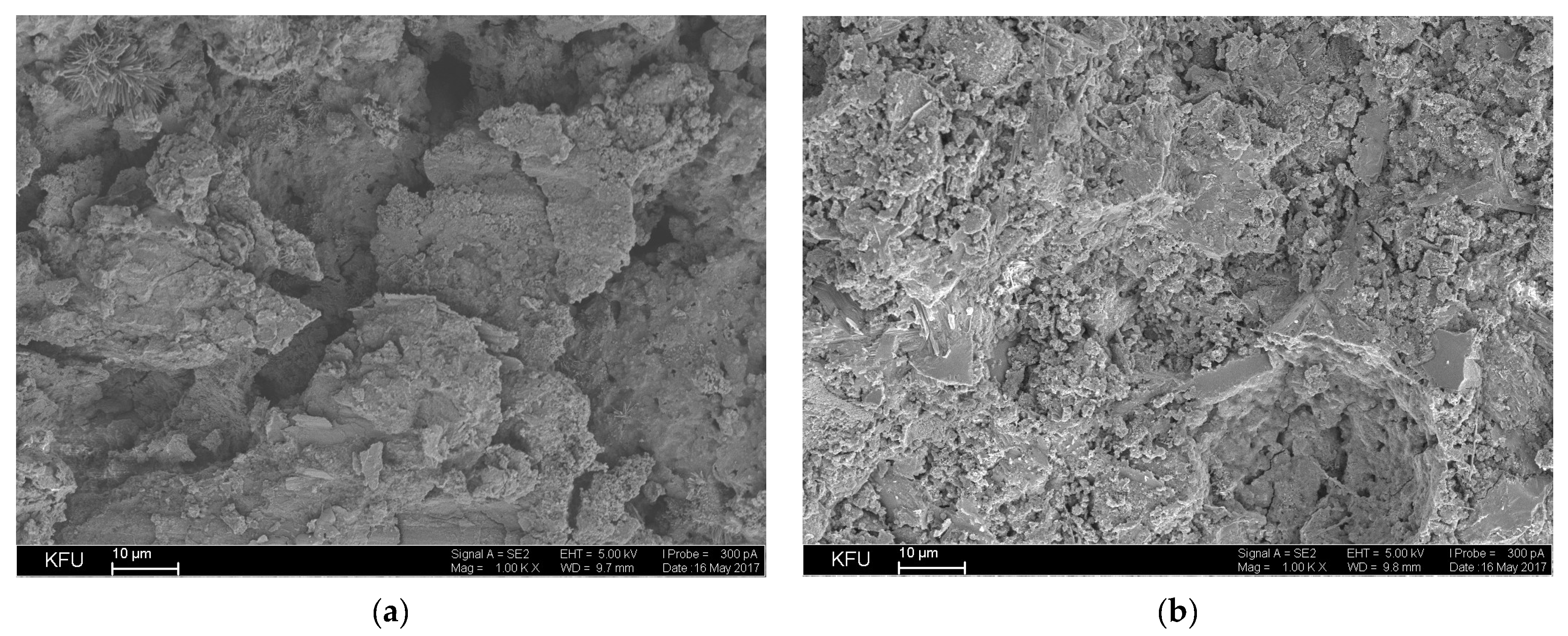
Using the BET method and mercury porosimetry, the characteristics of porosity and specific surface area of the fracture surface of cement stone, obtained at different processing durations in a vortex mill, were determined (
Table 3).
The specific surface area of the new formations in compositions obtained by mechano-magnetic activation increases by 15%, while the total pore volume decreases by 11%, and the average pore diameter decreases by 9%. A decrease in porosity leads to an increase in the density of the resulting samples, which, along with higher dispersity, also leads to an increase in strength. The fractures of the cement stone are shown in
Figure 9.
Thus, based on the data from
Table 3 and
Figure 9, a linear relationship has been established between the processing time of Portland cement in a vortex mill, the increase in the dispersity of Portland cement by the BET method, and the fracture surface of the cement stone (the amount of new formations).
4. Conclusions
A mathematical model of the motion of FBs in a vortex mill was implemented. The dependence of the FB’s velocity on the radial coordinate was calculated for various values of magnetic field induction and its gradient, showing that FBs can accelerate up to 50 m/s.
Based on the measured values of the specific surface area of the ground mineral component, an estimate of the required number of particle crushing cycles was made for different numbers of resulting parts after a single collision. For the case of grinding Portland cement, one to two disintegration cycles are sufficient to obtain the final form of the experimental particle size distribution. This conclusion is also confirmed by modeling the disintegration process using a binary fission approximation over two decay cycles. The theoretical distribution obtained from the initial experimental data agrees well with the measured distribution after 8 min of grinding Portland cement in the vortex mill, especially in the region of larger ground particles. It follows that a simple theoretical model of binary splitting can be quite applicable for an approximate description of the grinding process in a vortex mill.
It has been established that the main factors influencing particle destruction and activation during mechano-magnetic processing in a vortex mill are: (1) the magnitude of magnetic induction; (2) the gradient of magnetic induction (switching frequency of electromagnets); and (3) the magnetic susceptibility of the processed material. These factors determine the magnitude of the magnetic force acting on the FB, which provides its velocity in the working zone. In addition to this, magnetoplastic effects related to the properties of the processed material and its heating temperature, which increases during the operation of the VLA, can have a significant impact. As the magnetic susceptibility of the processed material increases, the processing efficiency—grinding and activation of particles—also increases.
The presence of two main zones for grinding mineral components in the apparatus’s working chamber has been identified: (1) a zone of mixing, grinding, and particle activation, where the velocity of ferromagnetic bodies is between 0 and 12 m/s, leading to the formation of a first group of ground particles with diameters greater than 1.0 μm; (2) a zone of intensive grinding and particle activation (velocity range of 12–50 m/s).
The following has been added to the conclusions section: the resulting mathematical model has a number of assumptions: ferromagnetic bodies, as well as the crushed material, are assumed to be spherical. In addition, the model of motion of ferrimagnetic bodies does not take into account the air resistance and the resistance of the crushed medium, which can make adjustments to the values obtained.
For the industrial implementation of a vortex mill, it is necessary to study the specific production conditions (the amount of necessary Portland cement for a one-time preparation of a concrete mixture) and then draw up a technical specification for the company producing the vortex mill with the required volume of the working chamber. Adjust the operating modes of the device in production.
In order to increase the efficiency of mechanomagnetic activation in a vortex mill, it is necessary to reduce the magnitude of the magnetic field gradient (equalize the magnitude of magnetic induction in the working chamber of the device). This can be achieved by using more powerful and productive inductors, increasing their number, which will increase the volume of the working chamber of the device and increase the overall productivity of the vortex mill. In addition, by changing the gradient of the magnetic field, the mixing zone can be adjusted depending on the tasks set in production: mixing or mainly grinding.
