Abstract
This study proposes a hybrid flexural strengthening technique for reinforced concrete (RC) beams by combining the near-surface mounted (NSM) and externally bonded reinforcement (EBR) methods. In this technique, iron-based shape memory alloy (Fe-SMA) strips are used for the NSM component, while either a carbon fiber reinforced polymer (CFRP) sheet or an Fe-SMA sheet is applied as the EBR component. The proposed hybrid-strengthening method aims to enhance the flexural load capacity and ductility of existing RC beams. To evaluate the effectiveness of the proposed method, numerical models were developed using ABAQUS software and validated against experimental results. A comprehensive numerical investigation was carried out on 52 RC beams, categorized into six groups with various hybrid-strengthening configurations. In addition, the effect of the prestressing of NSM Fe-SMA strips and the prestressing of EBR CFRP or EBR Fe-SMA sheet on the flexural performance of the beams was also examined. The results indicated that the hybrid-strengthening method significantly improved the cracking, yielding, and ultimate load capacities of the beams; however, in most cases, it reduced their deflection. Notably, prestressing the EBR Fe-SMA sheet in beams with higher reinforcement ratios produced a pronounced improvement in ductility.
1. Introduction
Reinforced concrete (RC) is one of the most widely used construction materials. However, RC structures can deteriorate due to factors such as inadequate design, poor construction or maintenance, unforeseen loading conditions, and aging []. These factors can lead to significant structural issues, including cracks, deformations, and steel reinforcement corrosion []. RC beams, as one of the primary structural members of buildings and bridges, are designed to undergo rapid bending during their service life. As a result, there is a growing demand for effective methods to strengthen and rehabilitate RC beams to ensure their longevity and safety [,,]. The selection of an appropriate strengthening method depends on the specific type and extent of damage in the RC beam. Commonly used flexural strengthening methods for RC beams include externally bonded reinforcement (EBR) [,] and near-surface mounted (NSM) [,] techniques.
Carbon fiber reinforced polymer (CFRP) is a commonly used material for flexural strengthening of RC beams, available as sheets, fabric, or rods [,,]. CFRP offers exceptional properties, including a high strength-to-weight ratio, high durability, high tensile strength, and resistance to corrosion and fire. Typically, a CFRP sheet is attached to the tension face (soffit) of the RC beam using the EBR or NSM techniques. However, the effectiveness of this strengthening method is influenced by several factors, including the number and orientation of CFRP layers, the dimensions and mechanical properties of the CFRP, the concrete surface preparation quality, and the design of intermediate and/or end anchorage systems [,,]. The performance and failure mechanisms of CFRP-strengthened RC beams are complex and depend on the interaction between the CFRP and the existing concrete substrate. Recent research has identified several critical failure modes, including CFRP rupture, concrete crushing, intermediate crack-induced debonding, and end peeling []. To mitigate premature debonding, various anchorage techniques have been developed, including mechanical clamping devices, CFRP U-wraps, and hybrid systems [,,]. A significant challenge is that typically only a limited tensile capacity (10–20%) of the CFRP is utilized prior to the failure of the RC beams. To address this limitation and utilize a higher tensile capacity of the CFRP sheets, prestressing techniques are often employed []. Prestressing CFRP can significantly enhance crack resistance and reduce deflection in the RC beam, which is beneficial for the service limit state [,]. Beams strengthened with the CFRP prestressing system exhibit less deflection and curvature at failure compared to non-prestressed CFRP-strengthened beams [,,]. Furthermore, prestressing improves the ductility of the strengthened beams compared to non-prestressed strengthened beams []. Finally, various factors, including adhesives, the prestressing technique, the level of prestressing, and the anchorages system, affect the failure mode of beams strengthened with CFRP. These factors must be taken into account during the design process.
Mostofinejad et al. [,] proposed an externally bonded reinforcement on grooves (EBROG) technique, an alternative flexural strengthening technique using CFRP. In this technique, unlike the conventional surface preparation in the EBR technique, longitudinal grooves are created on the soffit of the RC beam and filled with epoxy. This modification significantly enhances the ultimate load of the strengthened beam compared with the EBR technique due to higher stress transfer to the CFRP sheet. Similar to other strengthening methods, prestressing the CFRP is found to be effective in improving the crack resistance, yield, and ultimate load of the RC beam, though it still reduces the ductility of the beam [].
In recent years, the application of iron-based shape memory alloys (Fe-SMAs) for strengthening RC beams has received significant attention due to distinctive advantages, primarily centered on their self-prestressing capability and ability to ensure a ductile failure mode [,,,,,]. The characteristics of the Fe-SMAs include shape memory effect, superelasticity, durability, wider thermal hysteresis, cost-effectiveness, and corrosion resistance.
Similar to CFRP strengthening, EBR, Externally Unbonded (EUB), NSM, and cover replacement techniques can be employed to strengthen RC beams with Fe-SMA plates, strips, and bars []. The key to the performance of Fe-SMA systems is the utilization of the shape memory effect, where the alloy, prestrained in the factory, is installed, anchored, and then activated on-site, typically by heating using an infrared heater or a propane torch. The full recovery stress is generated after the Fe-SMA cools []. This self-prestressing eliminates the need for mechanical jacking and anchoring equipment required for traditional systems. The process induces a compression force along the strip’s length, which generates a constant negative moment and results in a cambering effect (upward displacement) in the beam []. Studies confirmed the feasibility of using Fe-SMA strips for prestressed strengthening [,,]. Shahverdi et al. [] investigated the flexural performance of RC beams strengthened with Fe-SMA strips using the NSM technique. The Fe-SMA strips were prestressed using the electrical resistance heating method. The Fe-SMA strips improved the flexural performance of the beams; however, prestressing the Fe-SMA strips further increased the cracking, yield, and ultimate loads of the RC beams [,]. Strengthening RC beams by prestressing Fe-SMA strips using an externally unbonded technique also exhibited ductile behavior and significantly improved the cracking and ultimate loads [,]. Comparatively, RC beams strengthened with prestressed Fe-SMA strips exhibited much better ductility and energy absorption capability than those prestressed with CFRP strips [,].
In terms of serviceability and stiffness, Fe-SMA demonstrates superior performance compared to CFRP. Activated Fe-SMA bars or plates effectively produce prestresses that significantly increase the resistance to bending deformations []. Experimental studies show that Fe-SMA plates significantly reduced cracking, improved elastic stiffness (by 6.3–24%), and increased characteristic loads compared to unstrengthened beams [,]. Under identical initial pre-stretch conditions, attaching Fe-SMA plates was found to be more conducive to improving beam stiffness compared to using CFRP tendons []. The prestressing action increases the cracking load; for instance, specimens with Fe-SMA plates exhibited cracking loads 48–113% greater than non-activated specimens. This improved performance results in better crack control, making Fe-SMA more suitable for improving the resilience of concrete beams compared to CFRP tendons []. Regarding load-bearing capacity, increasing the reinforcement ratio of Fe-SMA improves the load at the service limit state, ultimate load, and post-cracking stiffness []. Increases in Fe-SMA plate thickness and recovery stress generally enhance initial negative deflection, stiffness, crack load, and ultimate load []. Specifically, studies show that increasing the prestress level of Fe-SMA plates resulted in an 87.5% increase in crack load and a 70% increase in ultimate load compared to a reference beam []. However, applying prestress without activation resulted in markedly weaker performance []. For RC T-beams, increasing the Fe-SMA rebar diameter (e.g., from 6 mm to 12 mm) resulted in a 65% increase in ultimate load capacity []. The comparative analysis with CFRP highlights Fe-SMA’s strength in ductility and failure modes. While CFRP often results in brittle failure (e.g., strip rupture or debonding), Fe-SMA strengthened beams typically exhibit ductile failure due to yielding of internal steel and subsequent concrete crushing [,]. One study comparing large-scale RC beams found that the Fe-SMA reinforced beam exhibited ductile failure, while the prestressed CFRP counterpart experienced brittle failure []. Fe-SMA strips show a very ductile behavior in tension with large strains at failure, allowing for a ductile structural behavior of the strengthened element. Table 1 summarizes some of the recent studies on flexural strengthening using Fe-SMA and CFRP materials through different strengthening methods.
Previous studies have reported inconsistent trends regarding the flexural capacity and ductility of RC beams strengthened with CFRP and Fe-SMA materials. These variations mainly stem from differences in the mechanical interaction between the strengthening material and concrete substrate, as well as differences in bond-slip behavior, prestressing levels, and loading histories. For example, while some studies reported significant ductility loss in CFRP-strengthened beams due to brittle debonding or rupture [], others observed enhanced ductility when mechanical anchorage or hybrid configurations were adopted [,,]. Similarly, for Fe-SMA systems, variations in activation temperature, recovery stress, and bond characteristics significantly affect the prestress level and flexural response []. Mechanistically, higher recovery stress in Fe-SMA enhances initial stiffness and cracking load but may reduce post-yield ductility if the bond interface is too rigid []. These differences explain the conflicting observations in the previous studies and highlight the need for systematic hybrid approaches that balance stiffness and ductility through optimized prestressing and bonding mechanisms.
Despite these research efforts, a significant gap remains in the literature regarding the development and comprehensive evaluation of hybrid strengthening techniques that combine NSM Fe-SMA strips with EBR using either CFRP or Fe-SMA sheet to simultaneously enhance both the load capacity and ductility of RC beams. While CFRP excels in improving ultimate strength, it often compromises ductility, and Fe-SMA enhances ductility but may not achieve the same ultimate capacity as CFRP. Furthermore, the synergistic effects of prestressing both NSM and EBR components in a hybrid configuration have not been systematically investigated across various configurations.
To address this gap, this study proposes a novel hybrid strengthening method that integrates NSM Fe-SMA strips with EBR CFRP or Fe-SMA sheet, evaluating their combined effects on the flexural performance of RC beams through finite element (FE) analysis. For this purpose, 52 RC beams divided into six groups with various hybrid strengthening configurations are considered. In the following section, the details of the experimental tests on RC beams from the reference [], as well as the strengthening configurations, are described. Following this, the detailing of RC beams with various hybrid strengthening configurations is explained. Following this, the modelling details of the beams using the ABAQUS FE software (Version 2022) [] are described, and the beam models are validated against the experimental results. This validation served as a benchmark for assessing the structural performance of beams under consistent boundary and loading conditions. A comprehensive comparative study between the different strengthening configurations is provided. Accordingly, the findings presented herein are intended to demonstrate the comparative behavior and potential of the proposed hybrid technique rather than to generalize the results across all design configurations.

Table 1.
Summary of Flexural Strengthening of RC beam Studies using Fe-SMA and FRP.
Table 1.
Summary of Flexural Strengthening of RC beam Studies using Fe-SMA and FRP.
| Reference | Method | Material | Prestressing | Observations | Limitations/ Recommendations |
|---|---|---|---|---|---|
| Abouali et al. [] | NSM strips | Fe-SMA and CFRP strips | Self-activated | Fe-SMA showed a better ductile performance than CFRP | NSM Fe-SMA is efficient for strengthening beams with a low steel reinforcement ratio. |
| Michels et al. [] | EUB with end anchorage | Fe-SMA strips (compared to unstressed CFRP) | Self-activated | Proposed new strengthening method with easy and fast installation; Very ductile behaviour; End anchorage mitigates possible prestressing losses that are small. | Relaxation and fatigue issues require future investigation. |
| Rojob and El-Hacha [] | NSM with end anchorage | Fe-SMA bars | Self-prestressed | Enhanced flexural capacity of beams at service and ultimate conditions; Increased ductility. | Smooth Fe-SMA bars cause debonding with the groove materials; Investigation for the freezing-and-thawing cycles and under sustained loading should be conducted. |
| Hong et al. [] | NSM | Fe-SMA strips (compared to CFRP) | Self-activated | Eliminate the need for hydraulic jacks for prestressing; Prestressing caused chambering effect; | Prestress loss due to creep/shrinkage can be easily recovered by re-applying electric resistance heating. |
| Raad and Parvin [] | NSM rods | Coupled CFRP-Fe-SMA and GFRP-Fe-SMA | Self-activated | Coupled GFRP-Fe-SMA rods had higher ductility than the CFRP-Fe-SMA; Coupling CFRP or GFRP with Fe-SMA leads to higher ductility; Coupling reduces the number of cracks | Design criteria should be established to find an optimum value for coupling the materials |
| Qiang et al. [] | EUB | Fe-SMA plates (compared to CFRP tendons) | Prestressed (Self-activated) | Reduced cracking; Improved stiffness (6.3% to 24% increase); Superior performance and better crack control compared to CFRP under identical initial tensile force. | Prestressing level has a limited effect on the elastic stiffness; CFRP was less advantageous for stiffness and characteristic loads. |
| Kusuma et al. [] | Bottom or Side NSM | GFRP strips | None | Increase in ultimate capacity: 62.5% to 87.5%; High flexural capacity; Offers a higher long-term economy. | Strengthened beams failed by GFRP strip breaking or concrete cover detachment. |
| Alkhairo et al. [] | EUB with End-anchorage | SMA strips | Self-prestressing | Ultimate capacity enhanced by 22% to 66%; Service load improved by 28% to 95%; Exhibited very ductile behavior | Additional SMA layers have less impact on strengthening performance. Generated prestressing force is influenced by ambient temperature; Requires advanced activation techniques. |
| Khalil et al. [] | EBR (Embedded in concrete layer) | Fe-SMA bars | Prestressed | Restressing has less effect on beams with higher concrete compressive strength; Improved ductility by approx. 45%; Larger diameter bars improved strength by 65% and ductility by 47%. | Future experimental tests are required to validate the method. |
2. Methodology
2.1. Experimental Study
This section briefly explains the experimental database used for the validation of the FE beam models. Mostofinejad and Moghaddas [] studied the flexural behavior of RC beams strengthened using the EBR and EBROG methods. Twelve RC beams with a cross-section of 120 × 140 mm2 were cast and tested in the laboratory. These beams were divided into four groups with different reinforcement ratios. From these groups, two RC beams from each of Group C and Group B were selected based on the reinforcement ratio and failure mechanism for finite element model validation and comparative analysis in this study. As shown in Table 2, these four RC beams included two reference beams and two RC EBROG-CFRP strengthened beams. Beams in Group B had two 8 mm diameter tensile reinforcements, while those in Group C had three. An 8 mm diameter steel bar with a spacing of 30 mm was used for stirrups in all beams to prevent shear failure. For EBROG strengthened beams, CFRP wrap with a length of 850 mm and a width of 40 mm and 100 mm was used for Group B and Group C beams, respectively. With this arrangement, the failure mechanism of Group B resulted in FRP rupture after steel yield, while Group C’s failure mechanism was concrete crushing after steel yield, based on ACI 440.2R-08 code [].

Table 2.
Details of the RC beams [].
Concrete with a compressive strength of 30 MPa was used for all RC beams. Bars with an 8 mm diameter and yield and ultimate strengths of 340 MPa and 702 MPa, respectively, were used for the main reinforcement. Beams in Group B had 2 grooves on the tension face of the beam, each with a depth and width of 10 mm and 8 mm, respectively, while beams in Group C had 3 grooves of the same size. The grooves were filled with adhesive (Epoxydur C31), and then a CFRP wrap was attached to the soffit of the beams using adhesive (Epoxydur C300). Table 3 presents the material properties of the CFRP and adhesives used for strengthening the beams.

Table 3.
Material properties of CFRP and adhesive [].
A hydraulic jack with a capacity of 2500 kN was used to perform four-point tests on the beams. As shown in Figure 1, the beams were simply supported at the ends, and two displacement-controlled loads were applied to the beams at 50 mm from the center. The displacement was recorded at the mid-span of the beams using linear displacement transducers (LVDTs).

Figure 1.
(a) Schematic detailing of the RC beams, and (b) the test setup (unit: mm) [].
2.2. Detail of Beams
In this research, 52 RC beams with various strengthening configurations were considered to evaluate the effectiveness of different hybrid flexural strengthening methods through the numerical study. In the hybrid strengthening method, Fe-SMA strips were used for the NSM component, while a CFRP sheet or a Fe-SMA sheet was used for the EB component, as illustrated in Figure 2. Similar to the experimental study, the beams were categorized into Group B and Group C based on the reinforcement ratio and the number of grooves. The thickness of the CFRP sheet was 0.12 mm [], and the thickness of the Fe-SMA sheet was 1.5 mm []. The length of the CFRP sheet and Fe-SMA strip was 850 mm. In addition, the prestressing effect of NSM Fe-SMA strips, as well as the EBR CFRP or Fe-SMA sheet on the flexural performance of the beams, was investigated. The CFRP sheet was prestressed to 20% of its nominal ultimate strain, and a 2% pre-strain was considered for prestressing the Fe-SMA. It should be noted that a constant prestressing force was applied to all strengthened beams. Table 4 provides the details of the beam groups for numerical modeling.

Figure 2.
Details of the reinforcements and strengthening of the RC beams (unit: mm). (a) Longitudinal profile. (b) Cross-section.

Table 4.
Details of the beam models (unit: mm).
2.3. Finite Element Modeling
2.3.1. General Modeling
The plain concrete, grout, Fe-SMA strip, and Fe-SMA sheet were modeled using the three-dimensional (3D) solid element. The steel reinforcements were modeled using the 2D wire element. The CFRP sheet was modeled using the shell element. The simply supported boundary and loading conditions from the laboratory experiment were applied in the FE modeling. As illustrated in Figure 3a, one support was modeled as pinned conditions, where all translational degrees of freedom were restrained (U1 = U2 = U3 = 0). The other support was modeled as a roller, where the vertical and out-of-plane movement were restrained (U2 = U3 = 0), while the longitudinal movement was allowed. The load was applied through two rigid analytical plates placed 50 mm from the center of the beam according to the experimental setup. A kinematic coupling constraint was used to evenly distribute the displacement-controlled load applied from a central reference point, ensuring precise load application to the surface of the concrete beam. The prestressing of CFRP was defined as 20% of its ultimate nominal strain in the predefined field. The prestressing of Fe-SMA strips and sheet was considered as the initial stress in the predefined field, equal to the recovery stress of 387 MPa in the axial direction. Following the assignment of the prestressing forces, an initial step without any loadings was defined to achieve self-equilibrium without any additional loading.
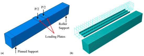
Figure 3.
(a) Loading and boundary conditions, and (b) mesh detailing of beam FE models.
2.3.2. Constitutive Modeling of Materials
Concrete
The concrete material was modeled using Concrete Damaged Plasticity (CDP). The CDP model combines concepts of plasticity and damage mechanics to accurately represent the progressive degradation of concrete due to cracking and crushing []. It accounts for the differences in tension and compression behavior, capturing the reduction in stiffness and strength as the material undergoes damage. It simulates the irreversible degradation of the modulus of concrete due to cracking by combining multiple hardening plasticity and isotropic damaged elasticity. Young’s modulus of 29 GPa and Poisson’s ratio of 0.15 were used to define the linear elastic and isotropic behavior of concrete. The nonlinear behavior of concrete was defined in terms of inelastic strain and corresponding yield stress. To simulate the uni-axial compressive stress–strain curve of concrete, the following equation was used []:
where is the compressive stress of concrete, is the compressive strain of concrete, is the peak compressive strength of concrete, is the strain corresponding to the peak compressive strength, and n is the empirical coefficient that controls the shape of the stress–strain curve, which is calculated as:
To simulate the uniaxial tensile behavior of cracked concrete, the exponential model of Belarbi and Hsu [] was employed for post-cracking behavior, as shown in Figure 4. The compressive and tensile strengths of the concrete in Group B were 43.6 MPa and 4.36 MPa, respectively, while those in Group C were 41.4 MPa and 4.14 MPa, respectively []. The viscosity parameter was set to the optimal level to maximize accuracy and minimize computational time. Table 5 shows the CPD parameters used in FE modeling, chosen based on well-established values for normal-strength concrete. These parameters were validated by accurately reproducing the load–deflection behavior observed in the experimental control beams. A dilation angle of 35° was used to capture the volumetric expansion of concrete under compression, and a viscosity parameter of 0.001 was applied to stabilize the numerical solution in the post-peak softening phase without significantly affecting the outcomes. The uniaxial compressive response was defined using Equations (1) and (2) up to the peak stress, after which it followed a linear decline to zero stress at a crushing strain of 0.0035. For tensile behavior, the Belarbi and Hsu model was used to describe the pre-cracking response, transitioning into a linear tension-softening phase characterized by a fracture energy of 0.1 N/mm to represent post-cracking behavior.
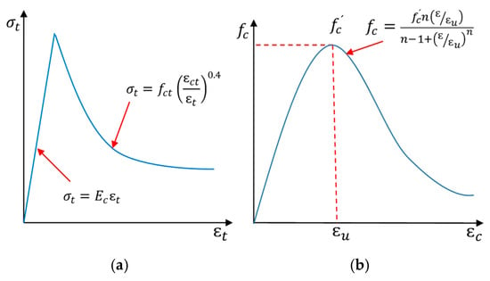
Figure 4.
Concrete response under uniaxial (a) tension, and (b) compression loads [].

Table 5.
The concrete parameters of the CDP model.
Steel
The elastic-perfectly plastic material model was employed to simulate the behaviour of steel material. The steel material used in the FE model for the reinforcements, including stirrups and tension bars of beams, had an elastic modulus of 207 GPa, and yield and ultimate strengths of 340 MPa and 702 MPa, respectively [].
CFRP
The CFRP material is assumed to exhibit orthotropic linear elastic behavior to accurately capture the anisotropic nature of the material. This means the material has different elastic properties depending on the direction of loading (longitudinal, transverse, and thickness). CFRP material properties, such as Young’s modulus and Poisson’s ratio, are defined for each direction. To predict failure, the Hashin failure criterion [] is employed. This popular approach for modeling failure initiation in FRPs considers five distinct failure modes: fiber compression and tension, matrix material failure, and inter-laminar shear stress [,]. Hashin’s failure criterion explains the failure modes of FRP by considering the failure of fibers and matrix, which can be obtained as follows:
Tensile failure of fibers (:
Compression failure of fibers (:
Tensile failure of matrix (:
Compression failure of the matrix (:
where and are the normal stresses in the longitudinal and transverse planes, XT and XC are the longitudinal tensile and compressive strengths, YT and YC are the transverse tensile and compressive strengths, SL and ST are the longitudinal and transverse shear strengths, and is the shear stress in the X plane, respectively. These limits facilitate the determination of the failure initiation and subsequent damage progression. This approach allows the model to capture the potential failure of the CFRP based on its material properties and the applied loading conditions. The mechanical properties of CFRP and the specific stress limits used in the model are detailed in Table 6 [].

Table 6.
CFRP material properties [].
Iron-Based Shape Memory Alloy
To accurately model the behavior of Fe-SMA, the mechanical properties of Fe-SMA were taken from a tensile coupon test conducted by Rosa et al. []. A standard round-bar coupon specimen made of Fe-17Mn-5Si-10Cr-4Ni-1(V, C) (ma,-%) SMA was subjected to uniaxial strain loading until fracture, based on ASTM E8/E8M guideline []. A bar of the same size was modelled and validated against the experimental results in this section. The Fe-SMA bar was modelled using 3D solid elements and meshed with C3D8R-type elements with continuum stress/displacement. The Fe-SMA had an elastic modulus of 184 GPa, a Poisson’s ratio of 0.359, and offset yield stresses, σp at 0.01% and σp at 0.2% of 267 MPa and 450 MPa, respectively. In addition, it had an ultimate stress of 950 MPa and an engineering fracture strain (Ꜫfrac) of 0.49. The isotropic hardening of stress–strain data from the coupon test was used to model the Fe-SMA. In addition, the ductile damage model with damage evolution for Fe-SMA was defined based on the relationship between fracture strain and stress triaxiality. This material model helped reduce mesh dependency in FE software. Figure 5 compares the results of the FE analysis with the experiment. As shown in this figure, the Fe-SMA bar fractured at the reduced section of the bar with high-stress concentration. The overall trend of the stress–strain curves from both the FE analysis and experiment matched each other. The ultimate stress of the bar from the FE analysis was 922 MPa at a strain of 0.1346, while it was 928 MPa at a strain of 0.1341 from the experiment, indicating a negligible difference of 6%. The verified stress–strain curve of the Fe-SMA with the same material model was used for the RC-beam models strengthened with the Fe-SMA.
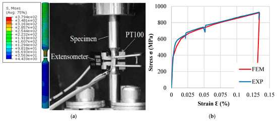
Figure 5.
Comparison of FE analysis and experimental results [] of the not-activated Fe-SMA bar. (a) Failure mechanism. (b) Stress–strain curves.
The offset method is used for prestressing (activating) the Fe-SMA. The intersecting slope of Young’s modulus (E) of Fe-SMA was offset by 2% of the strain (which is the recovery strain) []. Initially, the prestressing (the recovery stress of 387 MPa) was directly applied to the Fe-SMA, followed by the altered true stress–strain curve of the Fe-SMA shown in Figure 6 for the beams strengthened with the prestressed Fe-SMA.
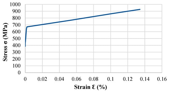
Figure 6.
Stress–strain curve of the prestressed (activated) Fe-SMA used in FE modeling.
Grout
The grooves were filled with SikaGrout-311, a flowable and expanding grout manufactured by Sika. The grout had a compressive strength of 90 MPa, a tensile strength of 3.2 MPa, and an elastic modulus of 37.2 GPa []. The CDP was also used for modeling the behavior of the grout material.
Adhesive
The bond behavior of the concrete-CFRP and concrete-SMA sheets was modeled using the traction-separation criterion []. The cohesive elements were placed along the bond interface, allowing the simulation to capture the progressive damage and ultimate failure of the adhesive bond. The slip and debonding of the CFRP and Fe-SMA sheets were assumed to arise from the cohesive failure of the adhesive. This approach captures the complex interaction between the concrete substrate and the composite materials. The cohesive zone model was employed to simulate the bond-slip relationship and debonding process. In this model, the bond interface is characterized by an initial linear elastic response followed by a softening phase that represents damage initiation and propagation. The triangular traction-separation model assumes an initial linear elastic behavior, where the traction is proportional to the separation distance between the bonded surfaces, as shown in Figure 7. The parameters defining this behavior include the maximum nominal stress (traction) and the corresponding separation at the onset of damage.
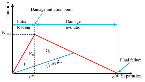
Figure 7.
Traction-separation model of the adhesive element [].
The adhesive material used to bond the concrete-CFRP and concrete-SMA sheets was a two-part epoxy resin, known for its high strength and durability. To define such behavior, the elasticity and shear moduli of the adhesive were used in the transverse and longitudinal directions, followed by damage initiation and evolution, and finally complete separation. The concrete-FRP and concrete-SMA interfaces were modeled using the bond-slip formulation of Lu et al. []. The pre-damage elastic behavior could be modeled as []:
where n, s, t are three perpendicular directions, one normal and two tangents to the surface. denotes the normal stress of the adhesive, and ts and tt are its shear stresses. Moreover, δn, δs, and δt represent the separations corresponding to n, s, and t directions, respectively. Lastly, Knn, Kss, and Ktt denote the elastic stiffness of the adhesive in the normal, first, and second shear directions. The cohesive behavior model was employed to simulate the mechanical contact of the adhesive. The initiation of adhesive damage was modeled using the quadratic traction criterion, using the following equation:
where is the normal traction strength (maximum nominal stress) of the adhesive, and and are the shear traction strengths (maximum nominal stress) in the first and second tangent directions, respectively. Upon initiation of the damage, the adhesive normal and/or shear stresses decrease until the ultimate failure occurs (i.e., final adhesive layer separation). This phase is referred to as damage evolution and follows the fractural energy (Gc) equation:
where is the critical fracture energy in the normal direction (tensile), and are the critical fracture energies in the first and second shear directions, respectively, is the fracture energy under mixed-mode loading (), is a reference energy release rate for normalization purposes , and η is the power law parameter for mixed-mode failure, taken as 1.45.
To define the cohesive zone model, a complete set of parameters is needed for elastic behavior, damage initiation, and damage evolution. The Knn, Kss, and Ktt characterize the elastic response. The onset of damage follows the first criterion from (Equation (8)), relying on the peak tractions. Mixed-mode fracture energies govern damage evolution in the model. All relevant parameters for the two adhesives, derived from manufacturer data [] and literature [], are shown in Table 7.

Table 7.
Mechanical properties of the interface (layup).
2.3.3. Interaction
The interaction between steel and concrete was simulated using the embedded constraint. The interaction between the grout and Fe-SMA strips was simulated using the tie constraint. The contact surface between the grout and the concrete beam was modeled with the tie constraint, considering fully bonded behavior. In addition, it was assumed that there is a perfect bond between the Fe-SMA sheet and the concrete, as well as between the CFRP sheet and the concrete. A cohesive traction-separation layer was directly modeled to represent the adhesive epoxy layer between the concrete face and the exterior bonded CFRP or Fe-SMA sheets. The nonlinear bond-slip and potential debonding behavior of the adhesive are captured in this cohesive zone by laws of damage initiation and evolution. The tie constraints were used only to bring the cohesive components into contact with the adjacent surfaces (i.e., connecting the cohesive layer to the concrete and to the CFRP/Fe-SMA sheet) to ensure compatible displacements across the interfaces. The risk of interfacial debonding was consequently not ignored; it was modeled using cohesive elements rather than the fully bonded interface assumption.
2.3.4. Mesh Discretization
For the plane concrete, grout, Fe-SMA strips, and Fe-SMA sheet, 3D eight-node solid brick elements (C3D8R) with three translational degrees of freedom (DOFs) per node were used. This element employs a reduced integration algorithm to prevent solution locking during iterative procedures. Two-node truss elements (T3D2) were used for the transverse and longitudinal reinforcements. The CFRP sheet was simulated using four-node shell elements with reduced integration (S4R) and hourglass control. Finally, the concrete-CFRP interface (adhesive phase) and groove adhesive were modeled using eight-node three-dimensional cohesive elements (COH38D). A mesh convergence study was performed to identify the optimal element size for analysis, balancing accuracy and computational efficiency. Element sizes ranging from 6 mm to 20 mm were tested. The optimal mesh size of 8 mm, where solution convergence was achieved with minimal computational cost, was determined (see Figure 3b). Furthermore, the numerical instabilities, such as hourglassing and anomalous stiffness in reduced-integration elements (C3D8R, S4R), were thoroughly examined to ensure the accuracy and reliability of the FE results. All the models were also monitored in the artificial hourglass energy (ALLAE), and it did not exceed 2.76% of the total internal strain energy (ALLIE) at the end of the ultimate load, which is within the accepted limit of 5% [].
2.4. Numerical Validation
To confirm the accuracy of the FE beam models, the results in terms of load–displacement curves and crack patterns were compared with those from the experimental study []. Figure 8 shows the load–displacement curves of the reference and EBROG strengthened beams from the experimental and FE analyses. As shown in this figure, the overall trend of the curves at the yield and ultimate stages from the FE analysis closely matches the experimental curves. The ultimate load of the reference beam in Group B from the experiment and numerical analysis was 35.18 kN and 34.19 kN, respectively, indicating a 2.8% difference. The ultimate load of the EBROG strengthened beam (B-CF-G2) from the FE analysis and experiment was 46.15 kN and 44.14 kN, respectively, showing about a 4.5% difference. Furthermore, the ultimate load of the reference beam in Group C from numerical and experimental analyses was 45.74 kN and 44.50 kN, respectively (about a 2.7% difference). The ultimate load of the EBROG strengthened beam (C-CF-G2) from the numerical and experimental analyses was 67.2 kN and 66.95 kN, respectively (about a 1% difference).
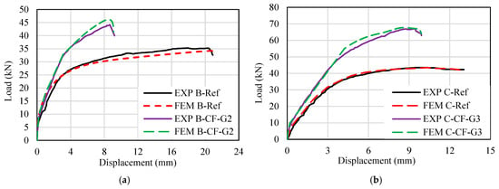
Figure 8.
Comparison of the load–displacement curves of beams from the numerical analysis and experiment study. (a) Group B beams. (b) Group C beams.
3. Results and Discussion
3.1. Crack Pattern and Failure Mode
Due to the large number of beams, only one representative beam from each configuration within Group C was selected for analysis of crack patterns and failure modes. Figure 9 presents the tensile crack patterns of the selected beams at the failure stage. The reference beam exhibited dominant flexural cracking, originating at the bottom surface (soffit), primarily within the mid-span region. These cracks propagated vertically upwards towards the center of the beam. Eventually, the reinforcement of the reference beam yielded, and the beam failed due to concrete crushing on the top surface directly under the indicated load points. Figure 9b,c shows the crack patterns of C-CF-G3-S12 and C-SMA-G3-S12 beams. These beams were strengthened with NSM non-prestressed Fe-SMA strips and EBR CFRP or Fe-SMA sheet without prestressing. While these beams’ failure modes were similar to that of the reference beam (failed due to concrete crushing after steel yielding), their crack patterns were different. Both of these beams exhibited a larger number of fine, closely spaced flexural cracks in the mid-span, along with diagonal shear cracks, compared with the reference beam. In addition, fewer major cracks reached the top of these beams, indicating improved crack control. Figure 9d,e shows crack patterns of strengthened beams with prestressed Fe-SMA strips and EBR non-prestressed CFRP (C-CF-G3-PS12) or Fe-SMA sheet (C-SMA-G3-PS12). Prestressing the Fe-SMA strip reduced the tensile stresses in the concrete, ultimately reducing the crack numbers in the beams. The failure mode of the C-CF-G3-PS12 beam was also similar to the reference beam; however, in the C-SMA-G3-PS12 beam, failure occurred due to concrete crushing after the yielding of the steel reinforcements and the Fe-SMA strip. Figure 9f,g show crack patterns of strengthened beams with non-prestressed Fe-SMA strips and EBR prestressed CFRP (C-PCF-G3-S12) or Fe-SMA sheet (C-PSMA-G3-S12). The failure mode of the C-PCF-G3-S12 beam was similar to the reference beam, whereas the failure mode of the C-PSMA-G3-S12 beam was due to concrete crushing after yielding of the steel reinforcement and the Fe-SMA strip. In addition, prestressing the CFRP sheet or Fe-SMA sheet improved the crack patterns of the beams compared with those of non-prestressed beams.
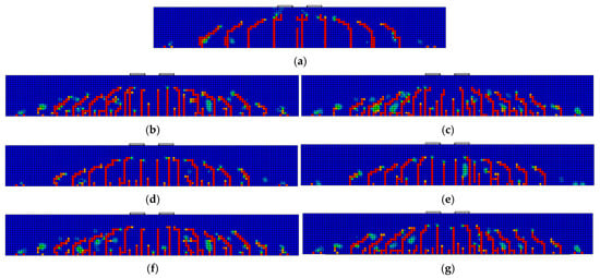
Figure 9.
Crack patterns (tensile damage) of the select RC beams at the failure stage. (a) C-Ref. (b) C-CF-G3-S12. (c) C-SMA-G3-S12. (d) C-CF-G3-PS12. (e) C-SMA-G3-PS12. (f) C-PCF-G3-S12. (g) C-PSMA-G3-S12.
Table 8 provides a quantitative comparison of key crack parameters at service load, including maximum crack width, average crack spacing, and cumulative cracked length. The reference beam, C-Ref, exhibited a maximum crack width of 0.24 mm, approaching the commonly adopted 0.3 mm limit. All strengthened beams demonstrated improved crack control, showing reduced crack widths and more uniformly distributed cracking. Prestressing the NSM Fe-SMA strips in C-CF-G3-PS12 and C-SMA-G3-PS12 beams led to the greatest reduction in maximum crack width (to 0.074 mm and 0.087 mm, respectively), representing a reduction of over 66% compared to the reference beam. Prestressing the EBR sheet in C-PCF-G3-S12 and C-PSMA-G3-S12 beams also reduced the maximum crack width to below 0.1 mm. Comparing beams with prestressed EBR CFRP and Fe-SMA sheet, both materials performed similarly well in controlling the maximum crack width at service load, with prestressed CFRP sheet in C-PCF-G3-S12 beam (0.085 mm) marginally outperforming prestressed Fe-SMA sheet in C-PSMA-G3-S12 beam (0.093 mm). All strengthened beams exhibited decreased average crack spacing and increased cumulative cracked length compared to the reference beam. This indicates a transition from a few wide cracks to many finely distributed micro-cracks, which benefits durability and serviceability. Beams with prestressed components, especially those with prestressed EBR sheet, exhibited the smallest average crack spacing, indicating a more uniform, finer crack distribution.

Table 8.
Comparison of crack parameters of select RC beams at service load.
3.2. Load-Deflection Behavior
To facilitate the discussion in this section, the results have been re-grouped into three major categories based on three hybrid-strengthening configurations. For the sake of comparison, in all the groups, the results of the reference beams and the beam strengthened using the EBORG method are also included. In this section, the load versus mid-span deflection curves of the beams are presented. In addition, the key performance responses of the beams strengthened using the hybrid-strengthening method were evaluated in terms of the load and displacement at the initial cracking (Pcr, Dcr), the yield (Py, Dy), and the ultimate load (Pu, Du), as well as the ductility, which are discussed and presented in tabular form. To calculate the yield displacement and force from the load–displacement curves, the equivalent elastic-plastic energy absorption method was used [].
3.2.1. NSM Strengthened Beams with Non-Prestressed Fe-SMA Strips and EBR Non-Prestressed CFRP or Fe-SMA Sheet
Figure 10 shows the load-deflection curves of beams strengthened with NSM non-prestressed Fe-SMA strips and EBR CFRP or Fe-SMA sheet without prestressing. As shown in this figure, both reference beams (in Groups B and C) had the lowest ultimate load with larger deformation compared to all strengthened beams in this category. Comparatively, the strength of the reference beam in Group C was higher than that of Group B, owing to its higher reinforcement ratio; however, it exhibited lower ductility.
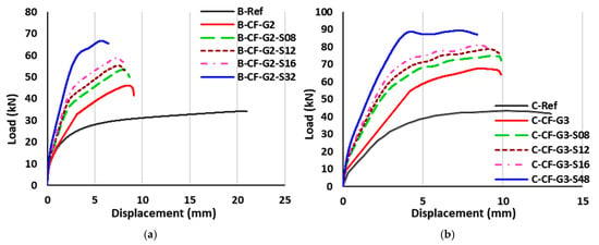
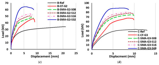
Figure 10.
Load-deflection curves of beams strengthened with NSM non-prestressed Fe-SMA strips and EBR non-prestressed CFRP or Fe-SMA sheet. (a) Group B1. (b) Group C1. (c) Group B2. (d) Group C2.
Strengthening beams with NSM Fe-SMA strips, along with the CFRP and Fe-SMA sheet, significantly improved the stiffness of the beams. In all groups of beams, as the cross-sectional area of the Fe-SMA strips increased, the strength of the beam increased; however, the ductile behavior of the beam reduced. Specifically, the plastic stage in the load-deflection curve of the beam substantially reduced as the cross-sectional area of NSM Fe-SMA strips increased, regardless of the EBR configurations. In both Group B and Group C, the hybrid-strengthened beams with NSM Fe-SMA strips and EBR Fe-SMA sheet showed better ultimate load and flexural performance compared to the hybrid-strengthened beams with NSM Fe-SMA strips and EBR CFRP sheet.
Figure 11 summarizes the key parameters for beams strengthened with NSM non-prestressed Fe-SMA strips and EBR CFRP or Fe-SMA sheet without prestressing. The hybrid strengthening improved the cracking load, ranging from 19% to 43%, and cracking displacement from 40% to 92% (maximum increase observed within each group). The maximum cracking load of 14.47 kN was observed for C-CF-G3-S48. Similarly, the yield load significantly increased in all hybrid-strengthened beams. Comparatively, the yield force in hybrid-strengthened beams with CFRP sheet was slightly higher than that of those with Fe-SMA sheet. In Groups B1 and B2, the yielding load of beams increased from 39% to 101%. Meanwhile, in Groups C1 and C2, the yielding load increment is from 71% to 108%. The ultimate load of hybrid-strengthened beams with CFRP sheet in Group B was slightly higher than that of the same hybrid-strengthened beams with Fe-SMA sheet. For instance, the ultimate load of B-CF-G2-S32 was 65.5 kN, which was 9% higher than that of B-SMA-G2-S32. The increment in ultimate load of hybrid-strengthened beams with CFRP sheet ranged from 46% to 109%, which was slightly higher than that of the same hybrid-strengthened beams with Fe-SMA sheet ranged from 37% to 106%. Nonetheless, the effect of the EBR CFRP sheet or Fe-SMA sheet on the ultimate displacement of strengthened beams was insignificant. The maximum ultimate load ranged from 50 kN to 65.5 kN for Group B beams strengthened with NSM Fe-SMA strips and CFRP sheet, and from 72 kN to 87 kN for Group C beams with the same strengthening configuration. Furthermore, the ultimate load of beams strengthened with NSM Fe-SMA strips and Fe-SMA sheet in Group B ranged from 47 kN to 60 kN, while for Group C beams, it ranged from 73 kN to 86 kN. The ductility of the strengthened beams increased as the Fe-SMA strip area increased. The ductility of most hybrid-strengthened beams was lower than the reference beams. The use of EBR Fe-SMA sheet improved the ductility of the hybrid-strengthened beams than the EBR CFRP sheet. This is mainly attributed to the mechanical characteristics of the Fe-SMA, which is a highly ductile material, and as the overall use of Fe-SMA increased in hybrid-strengthened beams, the ductility of the beams also increased for beams with smaller reinforcement ratios. Typically, the hybrid-strengthened beams with an overall lower area of Fe-SMA NSM reinforcement ratio failed due to rupture of the CFRP sheet (B-CF-G2-S08, B-CF-G2-S12, and B-CF-G2-S16), as the CFRP material significantly contributed to the load resistance of the hybrid strengthening system. However, the beams with a higher tensile reinforcement ratio and strengthened with a larger area of NSM Fe-SMA failed due to concrete crushing after yielding of the steel reinforcement and Fe-SMA strip.
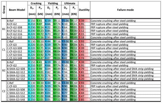
Figure 11.
Characteristic values for NSM strengthened beams with non-prestressed Fe-SMA strips and EBR non-prestressed CFRP or Fe-SMA sheet.
3.2.2. NSM Strengthened Beams with Prestressed Fe-SMA Strips and EBR Non-Prestressed CFRP or Fe-SMA Sheet
Figure 12 shows the load-deflection curves of beams strengthened with NSM prestressed Fe-SMA strips and EBR CFRP or Fe-SMA sheet without prestressing. As shown in this figure, the prestressing of NSM Fe-SMA strips significantly increased the elastic stiffness of the beam and reduced its inelastic behavior. Similar to Section 3.2.1, in all of these groups, as the area of the Fe-SMA strips increased, the stiffness of the beam also increased, while the deformation capacity decreased. In Group C3, the prestressing of Fe-SMA strips resulted in beams having similar force-displacement behavior, except for the C-CF-G3-PS48 beam. This similarity indicates that the effect of prestressing of Fe-SMA strips was more profound than increasing the strip area for beams with a higher reinforcement ratio and strengthened with an EBR CFRP sheet. Comparatively, the beams strengthened with EBR CFRP sheet (Groups B3 and C3) exhibited higher elastic stiffness with relatively lower inelastic deformations compared to the similar beams strengthened with EBR Fe-SMA sheet (Groups B4 and C4).
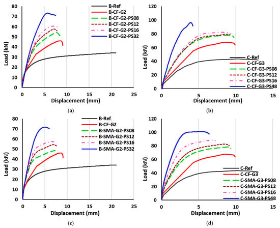
Figure 12.
Load-deflection curves of beams strengthened with NSM prestressed Fe-SMA strips and EBR non-prestressed CFRP or Fe-SMA sheet. (a) Group B3. (b) Group C3. (c) Group B4. (d) Group C4.
Figure 13 presents the key parameters for beams strengthened with NSM prestressed Fe-SMA strips and EBR CFRP or Fe-SMA sheet without prestressing. In the case of prestressed NSM Fe-SMA strips, the hybrid strengthening showed a significant improvement in the cracking load and displacement, with percentages ranging from 30% to 119% and 47% to 208% for cracking load and cracking displacement, respectively. This demonstrates a significant improvement in the cracking load and displacement compared with the respective results of Section 3.2.1, which is attributed to the prestressing of NSM Fe-SMA strips. This enhancement of cracking displacement was more profound for the hybrid-strengthened beams with the EBR CFRP sheet. Notably, the maximum cracking load of 22.2 kN was observed for beam C-SMA-G3-PS48 with the highest area of Fe-SMA strips. Generally, the yield force of beams strengthened with CFRP sheet (Groups B3 and C3) was slightly larger than that of those strengthened with Fe-SMA sheet (Groups B4 and C4). Prestressing the Fe-SMA strips slightly increased the yield force (ranging from 2% to 15%) of the hybrid-strengthened beams compared to similar beams without prestressing. The ultimate load of hybrid-strengthened beams with CFRP sheet in Groups B3 and C3 was found to be quite close to the respective values of the hybrid-strengthened beams with Fe-SMA sheet (Groups B4 and C4). In both cases, the beams of Group C were found to have a much higher ultimate load than the respective beams of Group B. Regarding the displacements at the ultimate load, similar observations to those for the ultimate load values can be made, as the results of Groups B3 and C3 were quite close to the respective results of the Groups B4 and C4, while the values of Group C were significantly higher than the respective values of Group B. The ultimate load ranged from 51 kN to 71.04 kN for Group B beams strengthened with NSM prestressed Fe-SMA strips and EBR CFRP sheet, and from 74.84 kN to 91.6 kN for Group C beams with the same strengthening configuration, values slightly higher than the respective results without prestressing. Similar observations can be made for the ultimate load of beams strengthened with NSM prestressed Fe-SMA strips and EBR Fe-SMA sheet (Group B), which resulted in values in the range of 47.09 kN to 70.48 kN, while for Group C beams, the ultimate load ranged from 76.43 kN to 97.61 kN. It can be observed that the ductility of the beams with the EBR Fe-SMA sheet (in Groups B4 and C4) was higher than the respective results of the beams with the EBR CFRP sheet (in Groups B3 and C3). The highest ductility of the hybrid-strengthened beams was achieved for beam C-SMA-G3-PS48 with a value equal to 2.85. This was attributed to the excellent ductile behavior of the Fe-SMA. The ductility of strengthened beams with EBR CFRP sheet was improved after prestressing the Fe-SMA strips, ranging from 4% to 46%. Group B4 beams strengthened with EBR Fe-SMA sheet also exhibited higher ductility (from 11% to 36%) after prestressing the Fe-SMA strips. However, the ductility of beams in Group C4 showed no changes as compared with Group C2 (with no prestressing). Notably, prestressing the Fe-SMA strips had no effect on the failure mode of the strengthened beams.
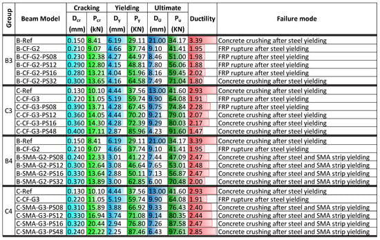
Figure 13.
Characteristic values for NSM strengthened beams with prestressed Fe-SMA strips and EBR non-prestressed CFRP or Fe-SMA sheet.
3.2.3. NSM Strengthened Beams with Non-Prestressed Fe-SMA Strips and EBR Prestressed CFRP or Fe-SMA Sheet
Figure 14 shows the load-deflection curves of beams strengthened with NSM non-prestressed Fe-SMA strips and EBR prestressed CFRP or Fe-SMA sheet. Similar to other hybrid-strengthened beams in other groups, as the area of Fe-SMA strips increased, the strength of the beam also increased, regardless of the configuration of hybrid strengthening. As shown in this figure, the prestressing of the EBR CFRP sheet increased the elastic stiffness of the beams in Groups B5 and C5. However, it slightly reduced the inelastic range of the strengthened beams, especially in Group B5. On the other hand, prestressing the EBR Fe-SMA sheet had a more profound effect on both the elastic and inelastic behavior of the hybrid-strengthened beams. Comparatively, load-deflection curves of beams strengthened with EBR prestressed Fe-SMA sheet showed better ductility compared with load-deflection curves of beams strengthened with EBR prestressed CFRP sheet. Notably, beams with EBR prestressed Fe-SMA sheet in Group C exhibited very good ductile behavior, very similar to the reference beam in Group C. Specifically, the load-deflection curve of the C-PSMA-G3-S12 beam achieved excellent inelastic behavior with higher strength compared to the reference beam.
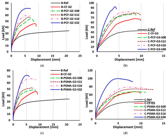
Figure 14.
Load-deflection curves of beams strengthened with NSM prestressed Fe-SMA strips and EBR non-prestressed CFRP or Fe-SMA sheet. (a) Group B5. (b) Group C5. (c) Group B6. (d) Group C6.
Figure 15 summarizes the key parameters for beams strengthened with NSM non-prestressed Fe-SMA strips and EBR prestressed CFRP or Fe-SMA sheet. Prestressing the EBR CFRP sheet or Fe-SMA sheet improved the cracking load of hybrid-strengthened beams, ranging from 30% to 119%, as well as the cracking displacement from 47% to 208%. In general, the cracking load and displacement of beams were enhanced when the EBR CFRP or Fe-SMA sheet was prestressed. Further, the prestressing of the EBR sheet (either CFRP sheet or Fe-SMA sheet) had an insignificant effect on cracking load and displacement compared to that of a similar beam with NSM prestressed Fe-SMA strips. Similar to other hybrid-strengthening configurations, the yield load of the beams significantly increased (ranging from 42% to 127%), while the yield displacement decreased (ranging from 1% to 55%). In Groups B5 and B6, the maximum yield load of 61 kN was observed for B-PCF-G2-S32 and B-PSMA-G2-S32 beams. In Groups C5 and C6, the maximum yield load was 82 kN and 85 kN for C-PCF-G3-S48 and C-PSMA-G3-S48 beams, respectively. Prestressing the EBR CFRP sheet or Fe-SMA sheet had a small impact on the yield load and displacement response of beams compared with the similar beams with the NSM prestressing Fe-SMA strips.
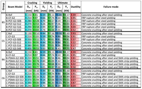
Figure 15.
Characteristic values for NSM strengthened beams with non-prestressed Fe-SMA strips and EBR prestressed CFRP or Fe-SMA sheet.
The maximum ultimate load for Group B5 beams strengthened with NSM Fe-SMA strips and prestressed CFRP sheet ranged from 49.23 kN to 70.91 kN, and from 74.81 kN to 87.75 kN for Group C5 beams with the same strengthening configuration. This means the ultimate load increased in a range of 44% to 108% for Group B5 and 80% to 111% for Group C5, as compared to the respective reference beam in each group. Furthermore, the ultimate load of beams strengthened with NSM Fe-SMA strips and prestressed Fe-SMA sheet in Group B6 ranged from 48.04 kN to 70.65 kN, while for Group C6 beams, it ranged from 66.49 kN to 92.10 kN. With respect to the reference beam in each group, the increase was 41% to 107% for Group B6 and 60% to 121% for Group C6. Like other hybrid-strengthening configurations, the ultimate displacement of the beams was reduced except for beams in Group C6, which showed higher flexibility and ultimate displacement compared to the other beams examined in this section.
Comparatively, the ductility performance of most of the hybrid-strengthened beams with prestressed EBR CFRP or Fe-SMA sheet was found to be higher compared to that of other hybrid-strengthened beams. Specifically, prestressing the EBR Fe-SMA sheet led to enhanced ductility of the strengthened beams, which was attributed to the excellent ductile behavior of Fe-SMA. The ductility of the C-PSMA-G3-S12 and C-PSMA-G3-S48 beams was 3.07 and 3.04, respectively, which was slightly larger than the ductility of the reference beam (C-Ref). It was also found that prestressing the EBR CFRP sheet or Fe-SMA sheet had no effect on the failure mode of the strengthened beams in these groups compared with the corresponding beams in the previous sections.
4. Conclusions
This study proposed a hybrid flexural strengthening technique for RC beams by combining NSM and EBR methods using CFRP and Fe-SMA materials. A numerical model was developed using ABAQUS and validated against the experimental results from Mostofinejad and Moghaddas []. An extensive numerical investigation on the effectiveness of various hybrid strengthening schemes was conducted on 52 RC beams across six groups. In addition, the effect of the prestressing of the NSM material, as well as the prestressing of the EBR material, was thoroughly studied. Based on the results of this research study, the following conclusions can be drawn:
- The proposed hybrid strengthening technique effectively improved the distribution and control of cracks in the beam. Prestressing the Fe-SMA strip reduced the tensile stresses in the concrete, ultimately decreasing the number of cracks in the beams. In addition, prestressing the EBR CFRP or Fe-SMA sheet resulted in more finely distributed cracks, indicating enhanced structural performance and delayed progression to failure.
- The hybrid strengthening technique resulted in a significant enhancement of the cracking load (up to 120%). Notably, the cracking load of beams with the EBR CFRP sheet was better than that of beams with the EBR Fe-SMA sheet due to the higher tensile strength of CFRP. In addition, prestressing the NSM Fe-SMA strips (up to 120%) or the EBR CFRP (up to 64%) or Fe-SMA (up to 119%) sheet enhanced the cracking load and displacement of the beam.
- The hybrid strengthening significantly enhanced the yield load of the beam; however, it reduced the yield displacement of the beam for all strengthening cases. In the absence of prestressing, the yield force in hybrid-strengthened beams with the EBR CFRP sheet (ranging from 49% to 108%) was slightly higher than that of those with the EBR Fe-SMA sheet (ranging from 39% to 105%). In general, the prestressing improved the yield load of the beam, while prestressing the NSM Fe-SMA strips led to a slightly higher yield load (up to 17%) than prestressing the EBR CFRP or Fe-SMA sheet.
- The ultimate load of the hybrid-strengthened beams reached 71kN and 97 kN in Group B and Group C, respectively, which was substantially higher than that of the reference beams (B-Ref: 34 kN and C-Ref: 46 kN). Prestressing either the NSM Fe-SMA strips or the EBR CFRP or Fe-SMA sheet led to a significantly higher ultimate load (ranging from 1 to 18%) compared to the hybrid-strengthened beam without prestressing. However, beams with NSM prestressed Fe-SMA strips exhibited slightly higher ultimate load (up to 14%) compared to beams with EBR prestressed CFRP or Fe-SMA sheet.
- The ductility of the beams decreased by up to 42% after strengthening without prestressing. The ductility of the hybrid-strengthened beams with the EBR Fe-SMA sheet ranged from 2.4 to 3.46, slightly higher than the respective beams with the EBR CFRP sheet (ranging from 2.05 to 2.45), which is attributed to the excellent ductile behavior of the Fe-SMA. Further, the ductility of beams with prestressed EBR CFRP or Fe-SMA sheet was up to 51% higher than that of the beams with NSM prestressed Fe-SMA strips.
- The failure of the hybrid-strengthened beams was found to be similar among all Group B beams, and almost the same failure mode was found for all Group C beams, with the exception of the beam with the lowest reinforcement ratio. The hybrid-strengthened beams with an overall lower area of NSM Fe-SMA reinforcement ratio failed due to the rupture of the CFRP sheet. In addition, the beams with higher tensile reinforcement and with a larger area of NSM Fe-SMA failed due to concrete crushing after yielding of steel/Fe-SMA.
Future research should perform experimental tests on beams strengthened using the proposed method and investigate the influence of other key parameters, such as pre-stressing levels and bond length, on the performance of hybrid-strengthened beams. Additionally, studies should evaluate material utilization efficiency and the load-capacity gain per unit prestress increment to establish the economic feasibility and optimize hybrid-strengthening systems for practical applications. It is important to note that the reported improvements in cracking and ultimate loads reflect analytical trends based on validated FE models rather than direct design values; therefore, further experimental calibration and code-based adjustments are necessary before practical design application. Moreover, integrating computer vision techniques could enhance the validation of crack patterns and failure modes in hybrid-strengthened RC beams. For example, advanced deep learning models such as DeepLab [], effective in semantic segmentation for precise crack detection, and EfficientNet [], known for efficient image classification to predict failure modes, could be adapted to automate the analysis of crack initiation and propagation from beam surface images. These vision-based approaches could provide quantitative data to complement numerical models, improving the understanding of structural behavior under different strengthening configurations.
Author Contributions
Conceptualization, A.J. and M.S.G.; methodology, M.S.G., A.J., and M.R.; software, M.S.G.; validation, M.S.G.; formal analysis, A.J. and M.R.; investigation, A.J.; resources, M.R.; data curation, A.J.; writing—original draft preparation, A.J. and M.S.G.; writing—review and editing, A.J., M.R. and A.L.; visualization, M.S.G.; supervision, A.J. and M.R.; project administration, A.J.; funding acquisition, A.J. and M.R. All authors have read and agreed to the published version of the manuscript.
Funding
This study was supported by Fuzhou University (Grant No. XRC-22046). The authors also acknowledge the support of the Australian Research Council (ARC), under Industrial Transformation Research Hub for Resilient and Intelligent Infrastructure Systems (RIIS) in Urban, Resources, and Energy Sectors (Grant No. IH210100048).
Data Availability Statement
The original contributions presented in the study are included in the article; further inquiries can be directed to the corresponding authors.
Conflicts of Interest
The authors declare no conflicts of interest.
References
- Hanif, M.U.; Ibrahim, Z.; Ghaedi, K.; Hashim, H.; Javanmardi, A. Damage Assessment of Reinforced Concrete Structures using a Model-based Nonlinear Approach—A Comprehensive Review. Constr. Build. Mater. 2018, 192, 846–865. [Google Scholar] [CrossRef]
- Mulk, S.; Usman, M.; Khan, A.; Usman, M.; Javanmardi, A.; Ahmad, A. Damage assessment of reinforced concrete beams using cost-effective MEMS accelerometers. Structures 2022, 41, 602–618. [Google Scholar] [CrossRef]
- Ghaedi, K.; Ibrahim, Z.; Javanmardi, A.; Jameel, M. Finite Element Analysis of a Strengthened Beam Deliberating Elastically Isotropic And Orthotropic CFRP material. J. Civ. Eng. Sci. Technol. 2018, 9, 117–126. [Google Scholar] [CrossRef]
- Alasadi, S.; Ibrahim, Z.; Shafigh, P.; Javanmardi, A. An Experimental and Numerical Study on the Flexural Performance of Over-Reinforced Concrete Beam Strengthening with Bolted-Compression Steel Plates: Part II. Appl. Sci. 2020, 10, 94. [Google Scholar] [CrossRef]
- Ghalehnoei, M.S.; Javanmardi, A.; Izadifar, M.; Koenders, E.; Ukrainczyk, N. Finite Element Analysis of Shear Reinforcing of Reinforced Concrete Beams with Carbon Fiber Reinforced Polymer. Buildings 2023, 13, 1034. [Google Scholar] [CrossRef]
- Hamoush, S.A.; Ahmad, S.H. Debonding of Steel Plate-Strengthened Concrete Beams. J. Struct. Eng. 1990, 116, 356–371. [Google Scholar] [CrossRef]
- Xie, M.; Hoa, S.V.; Xiao, X.R. Bonding Steel Reinforced Concrete with Composites. J. Reinf. Plast. Compos. 1995, 14, 949–964. [Google Scholar] [CrossRef]
- El-Hacha, R.; Rizkalla, S.H. Near-surface-mounted fiber-reinforced polymer reinforcements for flexural strengthening of concrete structures. Struct. J. 2004, 101, 717–726. [Google Scholar]
- Hassan, T.; Rizkalla, S. Investigation of bond in concrete structures strengthened with near surface mounted carbon fiber reinforced polymer strips. J. Compos. Constr. 2003, 7, 248–257. [Google Scholar] [CrossRef]
- Kaiser, H. Strengthening of Reinforced Concrete with Epoxy-Bonded Carbon-Fiber Plastics; ETH: Zürich, Switzerland, 1989. [Google Scholar]
- Garden, H.N.; Quantrill, R.J.; Hollaway, L.C.; Thorne, A.M.; Parke, G.A.R. An experimental study of the anchorage length of carbon fibre composite plates used to strengthen reinforced concrete beams. Constr. Build. Mater. 1998, 12, 203–219. [Google Scholar] [CrossRef]
- Issa, C.A.; AbouJouadeh, A. Carbon Fiber Reinforced Polymer Strengthening of Reinforced Concrete Beams: Experimental Study. J. Archit. Eng. 2004, 10, 121–125. [Google Scholar] [CrossRef]
- Buyle-Bodin, F.; David, E. Use of carbon fibre textile to control premature failure of reinforced concrete beams strengthened with bonded CFRP plates. J. Ind. Text. 2004, 33, 145–157. [Google Scholar] [CrossRef]
- Tan, K.H.; Saha, M.K. Long-Term Deflections of Reinforced Concrete Beams Externally Bonded with FRP System. J. Compos. Constr. 2006, 10, 474–482. [Google Scholar] [CrossRef]
- El-Hacha, R.; Soudki, K. Prestressed near-surface mounted fibre reinforced polymer reinforcement for concrete structures—A review. Can. J. Civ. Eng. 2013, 40, 1127–1139. [Google Scholar] [CrossRef]
- Garden, H.N.; Hollaway, L.C. An experimental study of the influence of plate end anchorage of carbon fibre composite plates used to strengthen reinforced concrete beams. Compos. Struct. 1998, 42, 175–188. [Google Scholar] [CrossRef]
- Spadea, G.; Bencardino, F.; Swamy, R.N. Structural behavior of composite RC beams with externally bonded CFRP. J. Compos. Constr. 1998, 2, 132–137. [Google Scholar] [CrossRef]
- Mukhopadhyaya, P.; Swamy, N.; Lynsdale, C. Optimizing Structural Response of Beams Strengthened. Ournal Compos. Constr. 1998, 2, 87–95. [Google Scholar] [CrossRef]
- Aslam, M.; Shafigh, P.; Jumaat, M.Z.; Shah, S.N.R. Strengthening of RC beams using prestressed fiber reinforced polymers—A review. Constr. Build. Mater. 2015, 82, 235–256. [Google Scholar] [CrossRef]
- Quantrill, R.J.; Hollaway, L.C. The flexural rehabilitation of reinforced concrete beams by the use of prestressed advanced composite plates. Compos. Sci. Technol. 1998, 58, 1259–1275. [Google Scholar] [CrossRef]
- Huang, Y.L.; Wu, J.H.; Yen, T.; Hung, C.H.; Lin, Y. Strengthening reinforced concrete beams using prestressed glass fiber-reinforced polymer—Part I: Experimental study. J. Zhejiang Univ. Sci. 2005, 6A, 166–174. [Google Scholar] [CrossRef]
- Cao, Q.; Zhou, J.; Wu, Z.; Ma, Z.J. Flexural behavior of prestressed CFRP reinforced concrete beams by two different tensioning methods. Eng. Struct. 2019, 189, 411–422. [Google Scholar] [CrossRef]
- Wang, W.; Dai, J.; Harries, K.; Bao, Q. Prestress Losses and Flexural Behavior of Reinforced Concrete Beams Strengthened with Posttensioned CFRP Sheets. J. Compos. Constr. 2012, 16, 207–216. [Google Scholar] [CrossRef]
- Xue, W.; Tan, Y.; Zeng, L. Flexural response predictions of reinforced concrete beams strengthened with prestressed CFRP plates. Compos. Struct. 2010, 92, 612–622. [Google Scholar] [CrossRef]
- Chen, C.; Chen, J.; Zhou, Y.; Sui, L.; Hu, B. Design of ductile H-anchorage for strengthening reinforced concrete beams with prestressed FRP. Constr. Build. Mater. 2021, 307, 124883. [Google Scholar] [CrossRef]
- Mostofinejad, D.; Shameli, S.M.; Hosseini, A. EBROG and EBRIG methods for strengthening of RC beams by FRP sheets. Eur. J. Environ. Civ. Eng. 2014, 18, 652–668. [Google Scholar] [CrossRef]
- Mostofinejad, D.; Moghaddas, A. Bond efficiency of EBR and EBROG methods in different flexural failure mechanisms of FRP strengthened RC beams. Constr. Build. Mater. 2014, 54, 605–614. [Google Scholar] [CrossRef]
- Tehrani, B.N.; Mostofinejad, D.; Hosseini, S.M. Experimental and analytical study on flexural strengthening of RC beams via prestressed EBROG CFRP plates. Eng. Struct. 2019, 197, 109395. [Google Scholar] [CrossRef]
- Rojob, H.; El-Hacha, R. Fatigue performance of RC beams strengthened with self-prestressed iron-based shape memory alloys. Eng. Struct. 2018, 168, 35–43. [Google Scholar] [CrossRef]
- Michels, J.; Shahverdi, M.; Czaderski, C. Flexural strengthening of structural concrete with iron-based shape memory alloy strips. Struct. Concr. 2018, 19, 876–891. [Google Scholar] [CrossRef]
- Abouali, S.; Shahverdi, M.; Ghassemieh, M.; Motavalli, M. Nonlinear simulation of reinforced concrete beams retrofitted by near-surface mounted iron-based shape memory alloys. Eng. Struct. 2019, 187, 133–148. [Google Scholar] [CrossRef]
- Yeon, Y.M.; Hong, K.N.; Lee, S.; Ji, S.W. Numerical study of RC beams strengthened with Fe-Based shape memory alloy strips using the NSM method. Appl. Sci. 2021, 11, 6809. [Google Scholar] [CrossRef]
- Ruiz-Pinilla, J.G.; Montoya-Coronado, L.A.; Ribas, C.; Cladera, A. Finite element modeling of RC beams externally strengthened with iron-based shape memory alloy (Fe-SMA) strips, including analytical stress-strain curves for Fe-SMA. Eng. Struct. 2020, 223, 111152. [Google Scholar] [CrossRef]
- Hong, K.; Lee, S.; Yeon, Y.; Jung, K. Flexural Response of Reinforced Concrete Beams Strengthened with Near-Surface-Mounted Fe-Based Shape-Memory Alloy Strips. Int. J. Concr. Struct. Mater. 2018, 12, 45. [Google Scholar] [CrossRef]
- Forrest, B.T.; El-Hacha, R. Research developments of a novel self-prestressing system for flexural strengthening reinforced concrete structures. Eng. Struct. 2025, 342, 120866. [Google Scholar] [CrossRef]
- Shahverdi, M.; Czaderski, C.; Annen, P.; Motavalli, M. Strengthening of RC beams by iron-based shape memory alloy bars embedded in a shotcrete layer. Eng. Struct. 2016, 117, 263–273. [Google Scholar] [CrossRef]
- Rojob, H.; El-Hacha, R. Self-prestressing using iron-based shape memory alloy for flexural strengthening of reinforced concrete beams. ACI Mater. J. 2017, 114, 523–532. [Google Scholar] [CrossRef]
- Khalil, A.; Elkafrawy, M.; Abuzaid, W.; Hawileh, R.; AlHamaydeh, M. Flexural Performance of RC Beams Strengthened with Pre-Stressed Iron-Based Shape Memory Alloy (Fe-SMA) Bars: Numerical Study. Buildings 2022, 12, 2228. [Google Scholar] [CrossRef]
- Raad, J.; Parvin, A. Iron-based shape memory alloy and fiber reinforced polymers rods for prestressed NSM strengthening of RC beams. Eng. Struct. 2020, 207, 110274. [Google Scholar] [CrossRef]
- Alkhairo, A.; Oukaili, N.; Al-Mahaidi, R. Flexural improvement of reinforced concrete beams strengthened with self-prestressing shape memory alloys. Adv. Struct. Eng. 2024, 27, 195–214. [Google Scholar] [CrossRef]
- Shahverdi, M.; Czaderski, C.; Motavalli, M. Iron-based shape memory alloys for prestressed near-surface mounted strengthening of reinforced concrete beams. Constr. Build. Mater. 2016, 112, 28–38. [Google Scholar] [CrossRef]
- Strieder, E.; Aigner, C.; Petautschnig, G.; Horn, S.; Marcon, M.; Schwenn, M.; Zeman, O.; Castillo, P.; Wan-Wendner, R.; Bergmeister, K. Strengthening of reinforced concrete beams with externally mounted sequentially activated iron- based shape memory alloys. Materials 2019, 12, 345. [Google Scholar] [CrossRef] [PubMed]
- Yeon, Y.M.; Lee, W.; Hong, K.N. Finite Element Analysis of Reinforced Concrete Beams Prestressed by Fe-Based Shape Memory Alloy Bars. Appl. Sci. 2022, 12, 3255. [Google Scholar] [CrossRef]
- Qiang, X.; Liu, Q.; Chen, L.; Jiang, X.; Dong, H. Experimental study on flexural performance of prestressed concrete beams strengthened by Fe-SMA plates. Constr. Build. Mater. 2024, 422, 135797. [Google Scholar] [CrossRef]
- Sun, Y.; Dong, Z.; Zhu, H.; Wu, G.; Sun, Z.; Sun, X.; Ghafoori, E. Investigation on effective prestress in Fe-SMA bars and flexural behaviour of damaged T-shaped RC beams strengthened by NSM method. Structures 2025, 72, 108289. [Google Scholar] [CrossRef]
- Qiang, X.; Yang, R.; Jiang, X. Failure analysis and design recommendations on prestressed concrete beams strengthened with Fe-SMA plates. Struct. Concr. 2025, 1–27. [Google Scholar] [CrossRef]
- Khalil, A.; Elkafrawy, M.; Hawileh, R.; AlHamaydeh, M.; Abuzaid, W. Numerical Investigation of Flexural Behavior of Reinforced Concrete (RC) T-Beams Strengthened with Pre-Stressed Iron-Based (FeMnSiCrNi) Shape Memory Alloy Bars. J. Compos. Sci. 2023, 7, 258. [Google Scholar] [CrossRef]
- Chang, X.; Wang, X.; Liu, C.; Huang, H.; Zhu, Z.; Wu, Z. Parametric analysis on the flexural behaviour of RC beams strengthened with prestressed FRP laminates. Structures 2023, 47, 105–120. [Google Scholar] [CrossRef]
- Mouring, S.E.; Barton, O.; Simmons, D.K. Reinforced concrete beams externally retrofitted with advanced composites. Adv. Compos. Mater. 2001, 10, 139–146. [Google Scholar] [CrossRef]
- Lamanna, A.J.; Bank, L.C.; Scott, D.W. Flexural strengthening of reinforced concrete beams using fasteners and fiber-reinforced polymer strips. ACI Struct. J. 2001, 98, 368–376. [Google Scholar] [CrossRef]
- Hsu, C.T.T.; Punurai, W.; Bian, H.; Jia, Y. Flexural strengthening of reinforced concrete beams using carbon fibre reinforced polymer strips. Mag. Concr. Res. 2003, 55, 279–288. [Google Scholar] [CrossRef]
- Papalou, A.; Triantafillou, T.C. Analytical and experimental study of flexural strengthening of RC members using mechanically fastened FRP strips. Adv. Compos. Lett. 2011, 20, 27–32. [Google Scholar] [CrossRef]
- SIMULIA. ABAQUS 6.14 Analysis User’s Manual. Abaqus 6.14 Documentation; Hibbitt, Karlsson and Sorensen, Inc.: Providence, RI, USA, 2019. [Google Scholar]
- Kusuma, Y.; Rashmi, T.; Anand, V.N.; Balaji, N.C. An experimental study on flexural performance of RC beams strengthened by NSM technique using GFRP strips for a resilient infrastructure system. Mater. Today Proc. 2022, 52, 1959–1967. [Google Scholar] [CrossRef]
- Bakis, C.E.; Balaguru, P.N.; Bank, C.A.B.L.C.; Benmokrane, A.B.B.; Blaszak, G.J.; Brown, J.V.L.B.G.L.; Dolan, T.I.C.C.W.; Duthinh, D.; Faza, R.M.E.S.S.; Gale, E.R.F.D.M. Guide for the Design and Construction of Externally Bonded FRP Systems for Strengthening Concrete Structures; ACI Committee: Farmington Hills, MI, USA, 2002. [Google Scholar]
- Shahverdi, M.; Michels, J.; Czaderski, C.; Motavalli, M. Iron-based shape memory alloy strips for strengthening RC members: Material behavior and characterization. Constr. Build. Mater. 2018, 173, 586–599. [Google Scholar] [CrossRef]
- Hanif, M.U.; Ibrahim, Z.; Ghaedi, K.; Javanmardi, A.; Rehman, S. Finite Element Simulation of Damage In RC Beams. J. Civ. Eng. 2018, 9, 50–57. [Google Scholar] [CrossRef]
- Popovics, S. A numerical approach to the complete stress-strain curve of concrete. Cem. Concr. Res. 1973, 3, 583–599. [Google Scholar] [CrossRef]
- Belarbi, A.; Hsu, T.T.C. Constitutive Laws of Reinforced Membrane Elements with High Strength Concrete. ACI Struct. J. 1995, 92, 562–573. [Google Scholar]
- Hashin, Z. Failure criteria for unidirectional fiber composites. J. Appl. Mech. Trans. ASME 1980, 47, 329–334. [Google Scholar] [CrossRef]
- Hashin, Z.; Rotem, A. A Fatigue Failure Criterion for Fiber Reinforced Materials. J. Compos. Mater. 1973, 7, 448–464. [Google Scholar] [CrossRef]
- Ahmad, A.; Khan, Q.u.Z.; Raza, A. Reliability analysis of strength models for CFRP-confined concrete cylinders. Compos. Struct. 2020, 244, 112312. [Google Scholar] [CrossRef]
- Rosa, D.I.H.; Hartloper, A.; de Castro e Sousa, A.; Lignos, D.G.; Motavalli, M.; Ghafoori, E. Experimental behavior of iron-based shape memory alloys under cyclic loading histories. Constr. Build. Mater. 2021, 272, 121712. [Google Scholar] [CrossRef]
- ASTM E8/E8M-16a. Standard Test Methods for Tension Testing of METALLIC Materials; ASTM International: West Conshohocken, PA, USA, 2016. [Google Scholar]
- Aktas, M.; Sumer, Y. Nonlinear finite element analysis of damaged and strengthened reinforced concrete beams. J. Civ. Eng. Manag. 2014, 20, 201–210. [Google Scholar] [CrossRef]
- Lu, X.Z.; Teng, J.G.; Ye, L.P.; Jiang, J.J. Bond—Slip models for FRP sheets/plates bonded to concrete. Eng. Struct. 2005, 27, 920–937. [Google Scholar] [CrossRef]
- Park, P. State-of-the Art Report Ductility evaluation from labratory and analytical testing. In Proceedings of the Ninth World Conference on Earthquake Engineering, Kyoto, Japan, 2–9 August 1988; pp. 605–616. [Google Scholar]
- Song, Z.; Zou, S.; Zhou, W.; Huang, Y.; Shao, L.; Yuan, J.; Gou, X.; Jin, W.; Wang, Z.; Chen, X.; et al. Clinically applicable histopathological diagnosis system for gastric cancer detection using deep learning. Nat. Commun. 2020, 11, 4294. [Google Scholar] [CrossRef] [PubMed]
- Kabir, H.; Wu, J.; Dahal, S.; Joo, T.; Garg, N. Automated estimation of cementitious sorptivity via computer vision. Nat. Commun. 2024, 15, 9935. [Google Scholar] [CrossRef]
Disclaimer/Publisher’s Note: The statements, opinions and data contained in all publications are solely those of the individual author(s) and contributor(s) and not of MDPI and/or the editor(s). MDPI and/or the editor(s) disclaim responsibility for any injury to people or property resulting from any ideas, methods, instructions or products referred to in the content. |
© 2025 by the authors. Licensee MDPI, Basel, Switzerland. This article is an open access article distributed under the terms and conditions of the Creative Commons Attribution (CC BY) license (https://creativecommons.org/licenses/by/4.0/).
