Abstract
Grain size plays a decisive role in governing the interface evolution and mechanical properties of ultra-thin metal composite foils. This study systematically investigates this relationship in roll-bonded C7701/Ti/C7701 (Cu-Ni-Zn alloy) composite foils. By controlling the initial grain size via pre-annealing, we demonstrate that a moderate grain size (~7–8 μm) optimally regulates a sequential “bonding–diffusion–intermetallic compound (IMC) formation” process at the interface. This results in a continuous, thin IMC layer and the best strength–ductility synergy (e.g., UTS ~217.5 MPa, elongation ~4.15%). In contrast, excessively fine or coarse grains lead to thick, brittle IMCs or interfacial defects, respectively, degrading performance. The mechanism by which grain size influences performance is revealed through a sequential mechanism of “bonding–diffusion–intermetallic compound formation.”
1. Introduction
Ultra-thin metal composite foils, which synergize the properties of dissimilar materials, have garnered significant interest for applications in flexible electronics, biomedical devices, and micro-electromechanical systems due to their superior functional and structural performance, offering advantages such as a high flexural stiffness-to-weight ratio and excellent yield resistance [1,2]. The fabrication of such laminated materials primarily relies on roll bonding technology [3]. During this process and the subsequent annealing, the bonding interface inevitably undergoes elemental diffusion and forms various intermetallic compounds (IMCs), which critically determines the final mechanical properties of the laminate [4,5,6,7]. However, a fundamental challenge in fabricating such micro-scale systems stems from pronounced size effects, which significantly influence both local deformation mechanisms and global process stability [8].
Grain size plays a pivotal role in this context, acting as a key microstructural parameter that governs the material’s behavior during both deformation and thermal processing. On the one hand, roll bonding and related severe plastic deformation processes like accumulative roll bonding (ARB) are effective methods for achieving grain refinement within the layers of composites [9,10]. On the other hand, the grain size itself has a profound effect on the interfacial phenomena. It influences the diffusional kinetics, as grain boundaries serve as rapid diffusion channels; an increase in grain boundary density enhances macroscopic diffusivity [11]. This directly affects the formation and growth of IMCs at the interface, which in turn impacts mechanical properties—a relationship that is also modulated by the grain size of the matrix phases [12]. Furthermore, the local strain distribution during deformation is heterogeneous and dependent on grain size, with larger grains potentially leading to more pronounced local stress concentrations [13].
The combination of titanium with copper-based alloys, such as the C7701 Cu-Ni-Zn alloy, is particularly attractive for designing advanced composite foils. Titanium offers high specific strength, excellent corrosion resistance, and biocompatibility [14,15], while C7701 provides superior electrical/thermal conductivity and corrosion resistance compared to pure copper [16]. Laminating them combines their respective advantages for potential applications in electronics, biomedicine, and marine engineering [17,18]. However, controlling the interface to achieve robust bonding without excessive growth of brittle IMCs remains a key challenge.
While existing studies have extensively explored the fabrication and properties of conventionally sized laminates, the specific role of pre-existing grain size in governing the interfacial evolution and final performance of ultra-thin composite foils remains less clear. In particular, a systematic understanding of the causal chain linking the initial grain size (prior to bonding) to the roll-bonding quality, subsequent interfacial diffusion behavior, IMC formation, and the resultant mechanical properties in such thin foil systems is lacking.
To address this gap, the C7701/Ti/C7701 composite foil system was investigated in this study. The primary objectives were as follows:
- (1)
- Systematically examine the effect of pre-rolling grain size (varied through pre-annealing at 400, 500, and 600 °C) on the interfacial microstructure after roll bonding and post-rolling annealing;
- (2)
- Correlate these interfacial characteristics with the tensile mechanical properties of the composite foils;
- (3)
- Elucidate the underlying mechanism by which grain size regulates performance through the sequential stages of mechanical bonding, interfacial diffusion, and intermetallic compound formation.
2. Equipment and Methods
The starting materials were 0.05-mm-thick commercially pure Grade 1 titanium foil (TA1) and C7701 copper-nickel-zinc alloy foil. Their chemical compositions comply with ASTM B265 [19] (Table 1) and the UNS C77000 [20] specification (Table 2), respectively. To control the initial grain size, both materials were subjected to pre-annealing treatments at 400 °C, 500 °C, and 600 °C for 1 h in a GR-TF60/18 heat treatment furnace (Shguier, Shanghai, China). The furnace chamber was evacuated and backfilled with high-purity argon (≥99.999%) three times prior to heating to minimize oxidation. The final annealing atmosphere was static argon, with a heating rate of 5 °C/min. After the isothermal holding, the samples were cooled by introducing a flow of room-temperature argon gas.

Table 1.
Chemical compositions of Ti, [wt.%].
Table 2.
Chemical compositions of C7701, [wt.%].
Prior to roll bonding, foil surfaces were chemically cleaned via pickling (30 vol.% HCl, 60 s), rinsing, and ethanol degreasing to remove oxides and contaminants. For roll bonding, a three-layer stack (C7701/Ti/C7701) with identical pre-annealing temperatures was assembled. The assembled pack was then roll-bonded at room temperature without lubrication using an S7-300 four-high rolling mill (roll diameter: 30 mm) under a constant rolling force of 800 N. The rolling speed was 3 rpm, corresponding to a linear velocity of approximately 4.7 mm/s. Rolling was conducted in two passes: the first pass reduced the total thickness from 0.15 mm to 0.09 mm (40% reduction), and the second pass further reduced it to the final thickness of 0.05 mm (44.4% reduction relative to the intermediate thickness).
All composite foils subsequently underwent a uniform post-rolling annealing at 600 °C for 1 h under the same argon atmosphere control and heating/cooling procedures as described for pre-annealing. Microstructural characterization was carried out using a KEYENCE VHX-5000 optical microscope (KEYENCE, Osaka, Japan) and a Zeiss Sigma 300 scanning electron microscope (SEM) (Carl Zeiss AG, Oberkochen, Germany) equipped with an energy-dispersive X-ray spectroscopy (EDS) detector (Bruker, GmbH, Bremen, Germany). Cross-sectional samples for metallographic and SEM observation were mounted using a graphite-based conductive mounting material at 140 °C for 12 min. They were then ground sequentially with SiC papers (400 to 1500 grit) and polished with 0.1 μm diamond paste. For optical microscopy, the C7701 layer was etched with a solution of Fe(NO3)3 in ethanol (1 g:25 mL), and the Ti layer was etched with a solution of HF:HNO3:H2O (1:1:8 by volume), both for 3–5 s. SEM observation and EDS analysis were performed at an accelerating voltage of 5 kV and a working distance of 8.5 mm, utilizing the High Definition Backscattered Electron (HDBSD) signal for compositional contrast and the SE2 signal for fracture morphology examination. Phase identification was performed using a Bruker D8-ADVANCE XRD analyzer (Germany) (Bruker, GmbH, Bremen, Germany) with Cu Kα radiation. For XRD analysis, composite foils were ground into powder. Scans were conducted over a 2θ range of 20–100° with a step size of 0.05° and a counting time of 0.05 s per step.
Tensile tests were performed on an XK-207s micro-tensile machine (Zhong LuChang, Jinan, China). Specimens with a gauge length of 15 mm were tested at a constant crosshead speed of 0.1 mm/min, corresponding to an initial nominal strain rate of approximately 1.7 × 10⁻⁴ s−1. An electronic extensometer was employed to accurately measure the longitudinal strain during testing. The force-displacement data recorded by the testing machine were converted into true stress–true strain curves based on the initial cross-sectional area and gauge length of the specimen, assuming uniform deformation prior to necking. The test was terminated upon complete fracture of the entire laminated specimen, not merely the failure of a single layer. At least three valid tests were performed for each condition. Grain sizes of the pre-annealed foils were determined using the linear intercept method according to ASTM E112, averaging measurements from at least ten independent fields of view per condition. The dimensions of the tensile test specimens and the experimental flowchart are shown in Figure 1.
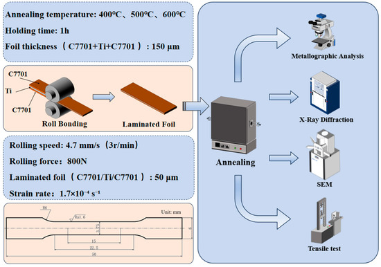
Figure 1.
The dimensions of the tensile test specimens and experimental flowchart.
3. Results and Discussion
3.1. Effect of Grain Size on Microstructure and Interfacial Properties
As can be seen from Figure 2a–c, the microstructure of C7701 foil annealed at 400 °C retains grains distributed along the rolling direction, and the theoretical recrystallization temperature of C7701 is 483 °C. It is obvious that the C7701 foil fails to recrystallize at 400 °C, single equiaxed grains generated in the C7701 foil annealed at 500 °C and 600 °C, and the grain size increases with the increase of the annealing temperature. The grain sizes were calculated to be 7.1 μm (500 °C) and 17.3 μm (600 °C), respectively.
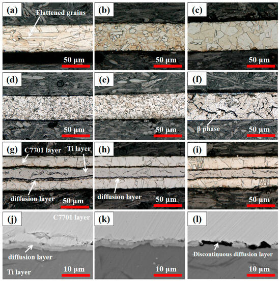
Figure 2.
Microstructure of the foils. (a–c) C7701 foil annealed at different temperatures. (a) 400 °C (b) 500 °C (c) 600 °C, (d–f) Pure titanium foil annealed at different temperatures. (d) 400 °C (e) 500 °C (f) 600 °C, (g–i) Composite foil in the corroded state. (g) 400 °C (h) 500 °C (i) 600 °C, (j–l) SEM image of composite foil interface. (j) 400 °C (k) 500 °C (l) 600 °C.
As can be seen from Figure 2d–f, the grain size of pure titanium increases with increasing annealing temperature. The grain sizes were 6.4 μm (400 °C), 7.5 μm (500 °C), and 16.7 μm (600 °C), respectively. The titanium foil annealed at 600 °C produced needle-like β-phases at the grain boundaries. The theoretical α→β phase transformation temperature of pure titanium is 882 °C. However, in thin foils, factors such as sample geometry, rapid cooling, and the protective argon atmosphere can significantly lower the actual transformation temperature. The smaller material size represents a smaller number of grains, a larger surface area, an increase in the proportion of surface atoms, and a higher surface energy, which reduces the phase transformation temperature [21,22]. The reduction in the number of grains due to the grain size effect leads to a consequent reduction in the number of grain boundaries, which reduces the hindrance to dislocation motion and the energy required for the phase transition, thus further reducing the phase transition temperature. Argon is used as a protective atmosphere for the annealing process in confined spaces, and a room-temperature argon gas flow is introduced for cooling at the end of the holding period, which ensures cooling efficiency and insulates against oxygen penetration. The possibility of oxygen dissolution into the pure titanium lattice was additionally prevented and lattice distortion was reduced, resulting in the generation of the β-phase at lower temperatures [23]. At the same time, due to the additionally low thickness of the material, the heat dissipation efficiency is additionally improved and the cooling rate is accelerated, which is conducive to the retention of the β-phase organization. Under the combined influence of these factors, the generation of the β-phase at a lower temperature than the theoretical phase transition temperature was finally realized.
From Figure 2g–i, it can be seen that there exists a clear demarcation line between C7701 and Ti. The color is darker after corrosion of the bonded interface of the sample. This is due to the fact that both the Ti foil and the C7701 foil undergo plastic deformation at both macroscopic and microscopic scales during the rolling process. Although cold rolling primarily achieves interlayer bonding through mechanical action, the intense pressure causes extremely high strain in localized areas of the interface, promoting initial atomic contact and the formation of localized “fresh surfaces.” This mechanical activation lays the groundwork for subsequent chemical reactions during the annealing process [24]. During the heating process, atoms of the main elements in Ti and C7701 alloys diffuse into each other. Under heating conditions, reactions readily occur to form a variety of intermetallic compounds (IMCs). These compounds are typically hard and brittle, possessing properties distinct from the base metals. Compared to pure metal substrates, the formed IMCs may exhibit different crystal structures, electronic structures, and optical properties. This results in different colors and lusters at the macroscopic level, such as a dark or black appearance. Furthermore, the simultaneous action of the two corrosive agents also contributes to the darker coloration of the interface [25,26,27].
Figure 2j–l shows the backscattering pictures of the composite foil, which clearly demonstrate that there is an obvious elemental lining at the interface, which further confirms that the elements of the two materials diffuse into each other during heat treatment; at the same time, it can be seen that at higher multiplicity, the samples at 600 °C before rolling are affected by the grain size effect, and there is an obvious rupture at the interface. This is because grain boundaries are significant diffusion channels, especially for materials with smaller grain sizes, where the dense grain boundaries facilitate diffusion. At 600 °C, the grain size is relatively large, and overly coarse grains may reduce grain boundary density, potentially affecting diffusion efficiency [28]. The plastic deformation capability of coarse-grained materials is typically inferior to that of fine-grained materials. Even after annealing at 600 °C to promote diffusion, if the interface contact itself is uneven or there are numerous macroscale pores during rolling, diffusion may struggle to adequately bridge these larger defects. For materials with larger grain sizes, the density of grain boundaries is relatively low, which may result in a reduction in the effective grain boundary diffusion pathway at the interface, ultimately leading to discontinuities in the diffusive interface.
Elemental analysis of the composite foil was performed as follows. Point scanning was conducted at the interface positions marked by asterisks in Figure 3a,d,g. Line scanning was carried out perpendicular to the interface along the yellow lines indicated in the same figures. Additionally, surface scanning was performed to obtain elemental distribution maps.
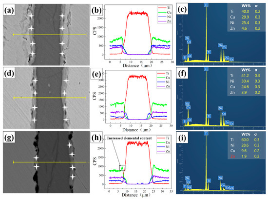
Figure 3.
Element distribution in composite foils point scanning and line scanning. (a,d,g) Point scan and line scan positions of elements. (a) 400 °C (d) 500 °C (g) 600 °C, (b,e,h) Curves of elemental line scanning results. (b) 400 °C (e) 500 °C (h) 600 °C, (c,f,i) Spectra of elemental point scanning results. (c) 400 °C (f) 500 °C (i) 600 °C.
The line scan results (Figure 3b,e,h) show that the elemental diffusion profiles across the interface are not abrupt, indicating a certain diffusion gradient exists. Specifically, the concentrations of Cu and Ni elements rise and then fall across the interfacial zone. The surface scan results (Figure 4a–c) further reveal that Cu and Ni elements exhibit obvious aggregation within the interfacial layer. In contrast, Zn tends to accumulate on the sample surface. The point scan results (Figure 3c,f,i) confirm that Zn content at the interface is minimal and almost negligible. The interfacial chemistry is thus dominated by Ti, Cu, and Ni.
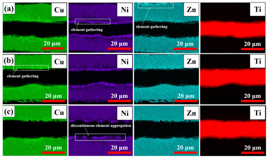
Figure 4.
Element distribution in composite foils surface scanning. (a) 400 °C (b) 500 °C (c) 600 °C.
This elemental distribution is due to significant mutual diffusion and reaction between Cu, Ni, and Ti, leading to IMC formation. This behavior is consistent with previously reported interface characteristics in Cu-Ni-Ti alloys and composite systems [29,30,31,32]. Additionally, the relatively high vapor pressure of Zn causes it to volatilize during high-temperature heat treatments such as annealing, especially if the inert atmosphere is not perfectly controlled. This results in the loss of Zn from the alloy surface and its extremely low content in the interface layer [33].
Compared to the monolayer foils, the grain size within the composite foil is significantly reduced, and an elemental diffusion layer forms at the interface. The physical constraint of the laminated structure limits grain growth, leading to finer grains in the composite. Furthermore, during rolling, the uneven distribution of grains at the interface can create randomly distributed stress concentrations due to the grain size effect. During subsequent annealing, these interfacial stress concentrations promote the nucleation of new grains under the influence of the interface effect. This process further restricts grain growth.
The high-temperature environment during annealing provides sufficient energy for metal atoms to migrate near the interface. This migration allows atoms originally present in each material to cross the interface into the other material, where elemental diffusion occurs.
XRD patterns of the composite foils annealed at different pre-annealing temperatures are presented in Figure 5. The dominant diffraction peaks were identified by comparing with standard PDF cards and corroborated with the EDS point-scan results (Figure 3c,f,i) and the Ti–Cu, Ti–Ni binary phase diagrams [34,35,36]. The primary intermetallic compounds formed at the interface were determined to be Ti2Cu (PDF#00-065-3512) and Ti2Ni (PDF#00-065-4574). These two phases share the same tetragonal crystal structure (space group I4/mmm), leading to significant peak overlap in the XRD patterns, which complicates individual quantification.
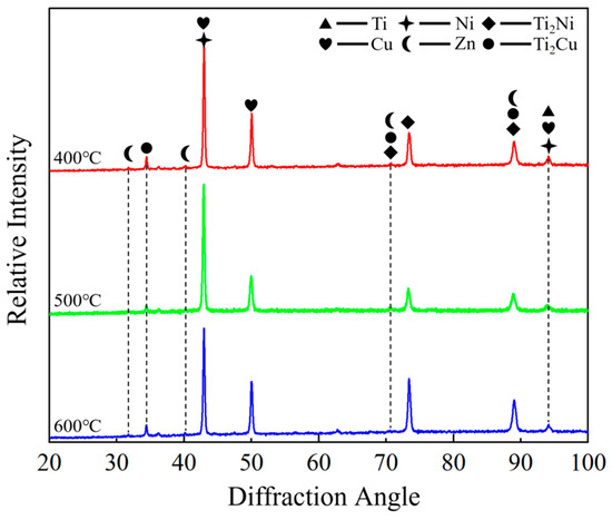
Figure 5.
XRD spectra of composite foils.
The predominance of Ti2Cu and Ti2Ni over other potential compounds such as TiCu, Ti3Cu4, TiNi, or Ti2Ni3 can be attributed to the following factors based on our experimental conditions and the existing literature: (1) Thermodynamic stability: In the Ti–Cu and Ti–Ni binary systems at the annealing temperature of 600 °C, the Ti2Cu and Ti2Ni phases are among the most thermodynamically stable and rapidly forming compounds adjacent to the Ti-rich side of the phase diagram [29,34,35]. (2) Local composition: The EDS point scans at the interface (Figure 3) consistently showed an atomic ratio of Ti:(Cu + Ni) close to 2:1, which aligns with the stoichiometry of Ti2Cu and Ti2Ni. (3) Kinetic constraints: The short annealing time (1 h) and the specific elemental diffusion gradients established during pre-annealing may kinetically favor the nucleation and growth of these binary phases over more complex ternary or other binary phases. While the ternary Ti–Cu–Ni system may introduce more complex phase equilibria, the strong similarity in the chemical behavior of Cu and Ni in Ti alloys, coupled with the observed Ti-rich local composition, suggests that the interface can be approximated as a combination of the two binary systems, resulting in the formation of Ti2(Cu, Ni)-type solid solutions.
It should be noted that a rigorous quantitative phase analysis (e.g., Rietveld refinement) was not performed due to the complex nature of the diffraction patterns, which include overlapping peaks from multiple phases (the matrix C7701, Ti, and the intermetallic compounds) and the textured nature of the rolled foils. However, the consistency between the identified phases, the EDS-derived local compositions, and the thermodynamic expectations provides strong support for our phase identification. Furthermore, a comparison of the XRD patterns across the three pre-annealing conditions (400, 500, and 600 °C) reveals no significant differences in peak positions or the emergence of new phases. This indicates that the final phase composition after the uniform 600 °C post-rolling annealing is largely independent of the initial grain size. The primary influence of the pre-annealing temperature (and thus initial grain size) was found to be on the thickness, continuity, and morphology of the intermetallic compound layer (as evidenced by SEM in Figure 2, Figure 3 and Figure 4), rather than on the type of phases formed.
In summary, microstructural and phase analyses confirm that the initial grain size, varied via pre-annealing, critically controls the interfacial evolution. While the final phase composition (Ti2Cu and Ti2Ni) is consistent, the grain size dictates the morphology, continuity, and thickness of the IMC layer. Finer grains promote more uniform diffusion but risk excessive IMC growth, whereas coarse grains lead to defective interfaces and inhomogeneous reactions.
3.2. Effect of Grain Size on the Mechanical Properties and Fracture Characteristics of Composite Foil
It is crucial to note that the tensile properties of ultra-thin composite foils are subject to significant scatter due to pronounced size effects [1,8]. The limited number of grains through the thickness and the dominant role of interfacial conditions mean that minor variations in microstructure or testing alignment can lead to considerable differences in measured stress-strain responses. Therefore, while Figure 5 provides the stress-strain curves from representative tests for each condition, the following discussion focuses on the qualitative trends and mechanistic insights derived from the curve profiles, fracture analysis, and their correlation with the observed interfacial microstructures (Figure 2, Figure 3 and Figure 4), rather than on direct comparisons of averaged quantitative values, which may be misleading under these conditions. The representative ultimate tensile strength (UTS) and elongation values for the curves shown are approximately 155.8 MPa and 4.77% for the 400 °C–pre-annealed sample, 217.5 MPa and 4.15% for the 500 °C sample, and 124.2 MPa and 2.25% for the 600 °C sample.
Different intermetallic compounds have different effects on the material properties, and in this paper we show that the diffusion and binding of elements essentially occurs in the elemental diffusion layer between the two foil layers, indicating that the distribution of intermetallic compounds is strictly limited to the diffusion layer part. The mixing of intermetallic compounds with different properties in a smaller space also cuts the elemental distribution of the composite foil.
The tensile properties of the composite foils, represented by the curves in Figure 6, clearly demonstrate the governing role of pre-annealing temperature (and thus initial grain size). Quantitatively, compared to the sample pre-annealed at 400 °C (UTS ≈ 155.8 MPa, elongation ≈ 4.77%), the sample pre-annealed at 500 °C exhibited a significant 39.6% increase in UTS (≈217.5 MPa) while retaining considerable ductility (elongation ≈ 4.15%). In stark contrast, the sample pre-annealed at 600 °C showed the poorest performance, with its UTS (≈124.2 MPa) and elongation (≈2.25%) being approximately 43.0% and 45.8% lower than those of the 400 °C sample, respectively.
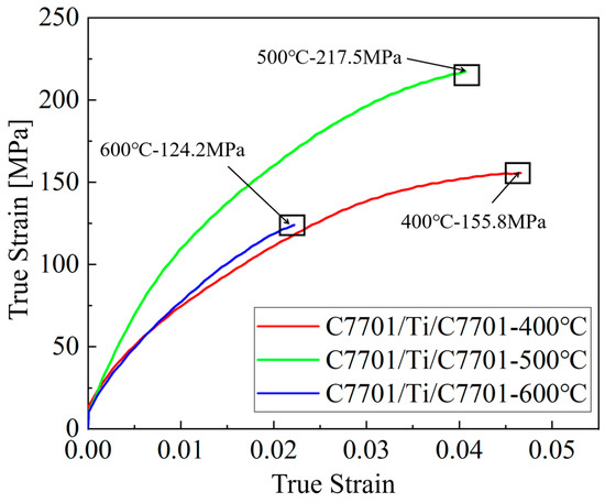
Figure 6.
Mechanical property curves of composite foils.
This pronounced difference is a direct manifestation of the grain-size-modulated “bonding-diffusion-intermetallic” cascade. The 500 °C pretreatment resulted in a moderate grain size (~7.1 μm for C7701, ~7.5 μm for Ti). This optimized the interfacial evolution in two key ways during roll bonding and subsequent annealing: (1) it ensured sufficient plastic deformability for effective mechanical interlocking; (2) it provided a balanced density of grain boundaries. This balance enabled adequate atomic diffusion (in contrast to the restricted diffusion in coarse-grained samples) to form a continuous, thin layer of Ti2Cu/Ti2Ni intermetallic compounds (IMCs), which strengthened the interface without severely compromising matrix plasticity.
Conversely, the 400 °C pretreatment produced excessively fine grains with a very high density of grain boundaries. These boundaries act as short-circuit paths for rapid atomic diffusion. Consequently, during annealing, this leads to an accelerated and excessive interdiffusion of elements, resulting in a thicker, more brittle IMC layer that increases strength at the expense of ductility.
For the 600 °C pretreatment, the coarse grains impaired plastic deformation during rolling, leading to inadequate mechanical interlocking and interfacial micro-defects (Figure 2). Furthermore, the low density of grain boundaries restricted diffusion pathways, causing incomplete interfacial reaction and localized elemental enrichment. Critically, as shown in Figure 2, needle-like β-phase precipitates formed along the grain boundaries of the pure Ti layer after 600 °C pre-annealing. The presence and coarsening of this β-phase additionally reduces the strength through two main mechanisms: (1) The softer β-phase acts as a site for strain localization and void formation; (2) The β/α phase boundaries serve as potent crack initiation sites. This synergy between interfacial defects and detrimental phase transformation explains the severe performance degradation.
As shown in Figure 7, the fracture morphology of the composite foils is characterized by three morphologies according to the C7701 layer, the diffusive layer, and the Ti layer. Intermediate Ti layers exhibit pronounced along-crystal fracture and a finite number of tough nests, which is due to the fact that pure Ti foils with larger grain sizes exhibit tough and brittle fracture behavior during fracture. As the grain size increases, this leads to deconvolutional cracks sprouting at the grain boundaries rather than cavities forming between grains. This leads to a rapid expansion of the brittle perforated crack along the deconvolution direction. These features coexist with a large number of tough nests due to plastic deformation, presenting a coexisting microscopic morphology of tough-brittle. The C7701 layer as a whole exhibits ductile fracture characteristics, with distinct dimples. Additionally, step-like cleavage facets and localized delamination traces are observed within this layer. This morphology is characteristic of laminated materials, where the mismatch in mechanical properties between layers can lead to progressive shear and interface decohesion as micro-cracks initiate and propagate under tensile loading.
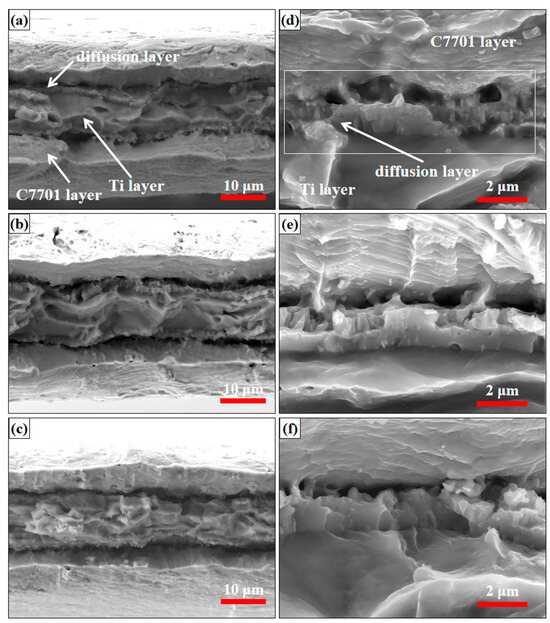
Figure 7.
Fracture morphology of composite foils; (a–c) Overall fracture morphology of composite foils. (a) 400 °C (b) 500 °C (c) 600 °C, (d–f) Fracture morphology at the interface of composite foils. (d) 400 °C (e) 500 °C (f) 600 °C.
A magnified view of the diffusion interface, as shown in Figure 7d–f, shows that the diffusion layer presents flat fracture with less disintegration order, which is due to the multiple intermetallic compounds formed by mutual diffusion of elements in the annealing stage after rolling. This leads to the difficulty of plastic deformation when the material is subjected to external forces, thus forming a very flat fracture along the disintegration surface of the crystal at low energy. At the same time, the disintegrating cracks are planar in the crystal, and a single disintegrating crack in a grain can simultaneously expand on two parallel disintegrating planes, eventually forming a disintegration step.
The fracture analysis corroborates the tensile data and interfacial observations. The optimal 500 °C condition exhibits a mixed-mode fracture with matrix dimples and controlled interface involvement. The 400 °C condition shows brittle cleavage facets associated with the thick IMC layer, while the 600 °C condition reveals severe delamination and interface decohesion, consistent with its poor bonding and low ductility. This directly links the macroscopic mechanical performance to the grain-size-governed microscopic failure mechanisms.
4. Conclusions
- Within the specific experimental system of this study (C7701/Ti/C7701 composite foil with 0.05 mm monolayer thickness, 800 N rolling force, and 600 °C post-rolling annealing), grain size plays a key regulatory role in roll-bonding effectiveness and interfacial elemental diffusion. Controlling the grain size via pre-rolling annealing temperature significantly influences the mechanical interlocking and elemental diffusion behavior at the interface during rolling. Finer grains (e.g., from the 400 °C pretreatment) provide fast diffusion channels through high-density grain boundaries, promoting interfacial diffusion but potentially leading to excessive reaction. Conversely, larger grains (e.g., from the 600 °C pretreatment) cause diffusion obstruction due to reduced grain boundaries, introducing interfacial defects and decreasing bonding strength.
- The synergy between the interfacial elemental diffusion gradient and intermetallic compounds (IMCs) governs the mechanical properties of the composite foils. Moderate diffusion (associated with grain sizes of ~7.1–7.5 μm) forms a thin and continuous (approximately 1–2 μm thick, based on SEM observation) layer of Ti2Cu/Ti2Ni IMCs. This enhances interfacial bonding and load transfer while preserving matrix plasticity, resulting in an optimal strength–ductility synergy (UTS ~217.5 MPa, elongation ~4.15%). Excessive diffusion (accelerated by grains <7 μm) leads to over-thickening of the brittle IMC layer (>3 μm), which increases strength but significantly compromises ductility (elongation decreases to ~4.77%). Insufficient diffusion (caused by coarse grains >15 μm and interfacial defects) results in localized elemental enrichment, β-phase coarsening, and poor interfacial bonding, promoting brittle fracture and severe degradation of both strength and ductility (UTS ~124.2 MPa, elongation ~2.25%).
- Grain size modulates mechanical properties through a sequential mechanism of “roll bonding → interfacial diffusion → IMC formation.” It governs this sequence by influencing the initial bonding quality (deformability) and the subsequent diffusion kinetics. A balanced, moderate grain size (~7–8 μm) achieves an optimal compromise, enabling sufficient interlocking and controlled diffusion to form a continuous, thin IMC layer for enhanced strength without severe ductility loss.
- The established grain-size-property relationship offers a practical guideline for tailoring interface-dominated properties in ultra-thin composite foils. Potential engineering implications include the micro-design of laminates for flexible electronics or micro-sensors where interfacial integrity is critical. The main limitation of this study is the focus on a fixed post-rolling annealing condition and a specific material pair. Future work should therefore explore the following: (i) the effects of varying annealing times and temperatures on the kinetic-structural interplay; (ii) the applicability of this mechanism to other dissimilar metal systems; and (iii) the performance of such grain-engineered foils under realistic service environments (e.g., cyclic loading, thermal exposure).
Author Contributions
Conceptualization, H.Z.; Methodology, H.Z. and T.Z.; Software, R.C.; Validation, H.Z.; formal analysis, Z.D. and R.C.; Investigation, R.C.; Resources, Z.D. and T.Z.; data curation, R.C. and Z.D.; writing—original draft preparation, R.C.; writing—review and editing, Z.D. and T.Z.; Visualization, Z.D.; Supervision, T.Z.; project administration, Z.D. and H.Z.; funding acquisition, Z.D. and T.Z. All authors have read and agreed to the published version of the manuscript.
Funding
This research was funded by the Liaoning Revitalization Talents Program, grant number XLYC2402029.
Data Availability Statement
The original contributions presented in this study are included in the article. Further inquiries can be directed to the corresponding authors.
Conflicts of Interest
The authors declare no conflicts of interest.
Nomenclature
| Abbreviation/Symbol | Meaning/Description |
| C7701 | A copper-nickel-zinc alloy (UNS C77000), nominal composition Cu-16.5/19.5Ni-bal.Zn (wt.%) |
| Ti, TA1 | Commercially pure titanium, Grade 1 (ASTM B265) |
| IMC(s) | Intermetallic compound(s) |
| UTS | Ultimate tensile strength |
| BSE | Backscattered electron (imaging mode in SEM) |
| SE2 | Secondary electron (imaging mode in SEM) |
| EDS | Energy-dispersive X-ray spectroscopy |
| XRD | X-ray diffraction |
| SEM | Scanning electron microscope |
| OM | Optical microscope |
| ARB | Accumulative roll bonding |
| β-phase | The body-centered cubic (bcc) phase of titanium, stabilized at high temperature or by specific processing conditions in this study. |
| α-phase | The hexagonal close-packed (hcp) phase of titanium, stable at room temperature. |
| Bonding–Diffusion–Intermetallic Cascade | The sequential mechanism proposed in this work, where grain size affects mechanical bonding during rolling, which in turn influences interfacial diffusion during annealing, ultimately determining the formation and morphology of intermetallic compounds. |
References
- Hermann, A.S.; Zahlen, P.C.; Zuardy, I. Laminated structures technology in commercial aviation—Present applications and future trends. In Laminated Structures 7: Advancing with Laminated Structures and Materials; Springer: Berlin/Heidelberg, Germany, 2005; pp. 13–26. [Google Scholar]
- Vinson, J.R. laminated Structures. Appl. Mech. Rev. 2001, 54, 201–214. [Google Scholar] [CrossRef]
- Lin, H.R.; Tian, Y.Z.; Sun, S.J.; Zhang, Z.F. Microstructural Evolution and Mechanical Properties of Laminated CuAl Composites Processed by Accumulative Roll-Bonding and Annealing. Acta Metall. Sin. (Engl. Lett.) 2021, 34, 925–931. [Google Scholar] [CrossRef]
- Mo, T.; Chen, J.; Chen, Z.; He, W.; Liu, Q. Microstructure Evolution During Roll Bonding and Growth of Interfacial Intermetallic Compounds in Al/Ti/Al Laminated Metal Composites. J. Miner. Met. Mater. Soc. 2019, 71, 4769–4777. [Google Scholar] [CrossRef]
- Luo, Z.; Zhang, Q.; Ma, X.; Wu, G. Microstructure evolution process of Ferro-Aluminum based laminated composite for electromagnetic shielding. Micron 2014, 64, 34–38. [Google Scholar] [CrossRef]
- Yang, H.M.; Zhu, P.X.; Zhou, S.G.; Xu, J.; Ma, H.Y.; Guo, J.X. Preliminary Research on Interfacial Evolution Behaviour of Ti-Cu Laminated Composite Materials. Adv. Mater. Res. 2011, 194–196, 1615–1619. [Google Scholar] [CrossRef]
- Inoue, H.; Ishio, M.; Takasugi, T. Texture of TiNi shape memory alloy sheets produced by roll-bonding and solid phase reaction from elementary metals. Acta Mater. 2003, 51, 6373–6383. [Google Scholar] [CrossRef]
- Imayev, R.; Gabdullin, N.; Salishchev, G. Effect of grain size on superplasticity of an intermetallic Ti3Al compound. Intermetallics 1997, 5, 229–236. [Google Scholar] [CrossRef]
- Lacaille, V.; Morel, C.; Feulvarch, E.; Kermouche, G.; Bergheau, J.-M. Finite element analysis of the grain size effect on diffusion in polycrystalline materials. Comput. Mater. Sci. 2014, 95, 187–191. [Google Scholar] [CrossRef]
- Liu, Y.G.; Zhou, J.Q. Effect of Grain Size Distribution on the Local Mechanical Behavior of Nanocrystalline Materials. Mater. Sci. Forum 2011, 682, 153–158. [Google Scholar] [CrossRef]
- Yu, L.; Chen, L.; Chen, Q.; Feng, L.; Xu, Z.; Nan, B.; Kang, X.; He, Y. Controlled fabrication and electrochemical corrosion behavior of ultrathin Ni-Cu alloy foil. J. Ind. Eng. Chem. 2021, 103, 118–123. [Google Scholar] [CrossRef]
- Sun, Y.; Hu, W.; Zhang, S.; Lu, Y.; Wang, J.; Ma, G.; Lin, J.; Hosseinkhani, S.; Ma, J.; Wang, Q. Corrosion fatigue behavior of porous Cu-bearing Ti alloy fabricated by selective laser melting. J. Mater. Res. Technol. 2023, 23, 1630–1643. [Google Scholar] [CrossRef]
- Li, Q.; Peng, Q.; Huang, Q.; Niinomi, M.; Ishimoto, T.; Nakano, T. Development and characterizations of low-modulus Ti–Nb–Cu alloys with enhanced antibacterial activities. Mater. Today Commun. 2024, 38, 108402. [Google Scholar] [CrossRef]
- Bolzoni, L.; Yang, F.; Paul, M. Development and characterisation of low-cost powder metallurgy Ti–Cu–Fe alloys. J. Mater. Res. Technol. 2023, 24, 2678–2687. [Google Scholar] [CrossRef]
- Sun, W.; Guo, J.; Zhang, W.; Li, X.; Chen, X. Microstructure and Strengthening Mechanism of Ti/Cu Laminated Composite Produced by Underwater Explosive Welding. J. Mater. Eng. Perform. 2020, 29, 5069–5079. [Google Scholar] [CrossRef]
- Geiger, M.; Kleiner, M.; Eckstein, R.; Tiesler, N.; Engel, U. Microforming. CIRP Ann. 2001, 50, 445–462. [Google Scholar] [CrossRef]
- Jiang, S.; Peng, R.L.; Jia, N.; Zhao, X.; Zuo, L. Microstructural and textural evolutions in multilayered Ti/Cu composites processed by accumulative roll bonding. J. Mater. Sci. Technol. 2019, 35, 1165–1174. [Google Scholar] [CrossRef]
- Zhang, B.; Wang, L.; Zhang, X.H.; Zhang, L. Microstructure Evolution and Mechanical Properties of the Ti/Ni Multilayer Composite Produced by Accumulative Roll Bonding. Rare Met. Mater. Eng. 2016, 45, 2352–2358. [Google Scholar]
- ASTM B265; Standard Specification for Titanium and Titanium Alloy Strip, Sheet, and Plate. American Society for Testing and Materials: West Conshohocken, PA, USA, 2025.
- UNS C77000; Standard Specification for Copper-Nickel-Zinc (Nickel Silver) Wire and Copper-Nickel Alloy Wire. ASTM International: West Conshohocken, PA, USA, 2017.
- Liu, H.W.; Lu, J.P.; Zheng, M.R.; Tang, S.H.; Sow, C.H.; Zhang, X.; Ke, L. Size effects on metal-insulator phase transition in individual vanadium dioxide nanowires. Opt. Express 2014, 22, 30748–30755. [Google Scholar] [CrossRef] [PubMed]
- Palai, D.; Dey, A.; Bera, P.; Bhattacharya, M.; Mallick, A.B.; Mukhopadhyay, A.K.; Sharma, A.K. Comprehensive studies on microstructural, electronic, thermo-optical, mechanical and tribological behavious of vacuum heat treated ultra thin CP Ti foils. Mater. Res. Express 2017, 4, 076404. [Google Scholar] [CrossRef]
- Gil, F.J.; Aparicio, C.J.; Planell, J.A. Effect of oxygen content on grain growth kinetics of titanium. J. Mater. Synth. Process. 2002, 10, 263–266. [Google Scholar] [CrossRef]
- Zhang, L.C. On the mechanism of cold rolling thin foil. Int. J. Mach. Tools Manuf. 1995, 35, 363–372. [Google Scholar] [CrossRef]
- Cao, M.; Chen, H.-Q.; Deng, K.; Duan, X.-W.; Liu, S.; Che, X.; Li, F. Effect of Interface on Mechanical Properties and Stamping Formability of Ti/Al Multilayered Composites. Met. Mater. Int. 2023, 29, 2413. [Google Scholar] [CrossRef]
- Tang, L.; Yao, D.; Xia, Y.; Liang, H.; Zeng, Y.-P. Effect of interfacial microstructure evolution on the peeling strength and fracture of silicon nitride/oxygen-free copper foil joints brazed with Ag-Cu-TiH2 filler. J. Eur. Ceram. Soc. 2023, 43, 4374–4385. [Google Scholar] [CrossRef]
- Zhou, P.F.; Yuan, M.N.; Pei, X.; Zhu, J.; Yang, W.; Wang, Y.; Zhou, X.; Zhao, Y. Study on strengthening and toughening mechanism of Ti-Ni-Al ternary metallic-intermetallic laminated composites: Effect of interlaminar phase and Ti2Ni morphology. Mater. Today Commun. 2024, 38, 108059. [Google Scholar] [CrossRef]
- Zhang, C.Q.; Liu, W. Abnormal effect of temperature on intermetallic compound layer growth at aluminum-titanium interface: The role of grain boundary diffusion. Mater. Lett. 2019, 254, 1–4. [Google Scholar] [CrossRef]
- Wang, L.; Liu, K.; Li, J.; Chen, Z.; Wang, J.; Okulov, A. Interfacial microstructure and mechanical properties of diffusion bonded joints of additive manufactured 17-4 PH stainless steel and TC4 titanium alloy. Vacuum 2024, 219, 112709. [Google Scholar] [CrossRef]
- Liu, K.; Li, Y.; Xia, C.; Wang, J. Microstructural evolution and properties of TLP diffusion bonding super-Ni/NiCr laminated composite to Ti-6Al-4V alloy with Cu interlayer. Mater. Des. 2017, 135, 184–196. [Google Scholar] [CrossRef]
- Thirunavukarasu, G.; Kundu, S. High-Strength Diffusion-Bonded Joints of 17-4 Stainless Steel and T64 Alloy Using Nickel and Copper Bilayer. J. Mater. Eng. Perform. 2020, 29, 515–528. [Google Scholar] [CrossRef]
- Raj, M.; Prasad, M.J.N.V.; Narasimhan, K. Microstructure and Mechanical Properties of Ti-6Al-4V Alloy/Interstitial Free Steel Joint Diffusion Bonded with Application of Copper and Nickel Interlayers. Metall. Mater. Trans. A 2020, 51, 6234–6247. [Google Scholar] [CrossRef]
- Tian, Y.; Luo, N.; He, W.; Jiang, B.; Pan, F. Effect of Zn and Ti transition foil on the microstructure and mechanical properties of hot rolling bonded Al/Mg composite plates. Mater. Sci. Eng. A 2024, 891, 145978. [Google Scholar] [CrossRef]
- Pripanapong, P.; Tachai, L. Microstructure and Mechanical Properties of Sintered Ti-Cu Alloys. Adv. Mater. Res. 2010, 93–94, 99–104. [Google Scholar] [CrossRef]
- Chatterjee, S.; Abinandanan, T.A.; Chattopadhyay, K. Phase formation in Ti/Ni dissimilar welds. Mater. Sci. Eng. A 2008, 490, 7–15. [Google Scholar] [CrossRef]
- Deng, Z.; Xu, K.; Tian, Y.; Lou, M.; Xue, R.; Zhang, L.; Liu, L.; Chang, K. Experimental investigation and thermodynamic re-assessment of the Ti–Zn system and atomic mobility of its bcc phase. Calphad 2022, 76, 102392. [Google Scholar] [CrossRef]


Disclaimer/Publisher’s Note: The statements, opinions and data contained in all publications are solely those of the individual author(s) and contributor(s) and not of MDPI and/or the editor(s). MDPI and/or the editor(s) disclaim responsibility for any injury to people or property resulting from any ideas, methods, instructions or products referred to in the content. |
© 2026 by the authors. Licensee MDPI, Basel, Switzerland. This article is an open access article distributed under the terms and conditions of the Creative Commons Attribution (CC BY) license.