Abstract
The study establishes key patterns in the influence of pre-applied impact-oscillatory loading (IOL) of varying intensity—realizing dynamic non-equilibrium processes (DNP)—in liquid nitrogen on the mechanical properties and structural state of stainless steel X10CrNi18-8. Static tensile deformation was investigated at room temperature following impulsive strain levels of εimp = 0.06–2.69%. A wave-like mechanical response of the steel to DNP was observed within this εimp range, most pronounced at εimp = 0.11% and εimp = 2.69%. After DNP at εimp = 0.11%, despite a maximum increase in ultimate strength by 5.25%, the relative elongation of the specimen increased to 10.3%. The scatter in ultimate tensile strength specimens across all loading regimes was within 6.38%, while the variation in ductility reached up to 21.25%. In contrast, after εimp = 2.69%, the stress–strain diagram resembled that of the steel in its initial state. Metallophysical investigations and X-ray diffraction analysis were conducted to explain the observed effects. At εimp > 2.7%, the high-strength but low-ductility X10CrNi18-8 steel undergoes brittle failure under impulsive loading. At the same time, the total fraction of the more brittle martensitic phase in the steel microstructure reaches approximately 22%.
1. Introduction
Stainless steels of various grades have found widespread application across numerous industrial sectors, including cryogenic engineering. Their use in cryogenic systems is particularly advantageous due to structural transformations—such as martensitic conversion—that occur at low temperatures, significantly enhancing mechanical properties compared to those at room temperature [1,2].
Considering these effects, many effective methods have been developed to improve the initial properties of stainless steels through the combined action of cryogenic treatment and various mechanical or physical influences [3,4,5]. For example, research on the effect of cryogenic laser shock peening on changes in the structural state and mechanical properties of stainless steels is actively developing [5]. Traditionally, the mechanical properties of stainless steels at cryogenic temperatures are evaluated under uniaxial tension at different strain rates, impact bending, cyclic loading, and specialized procedures for assessing fracture toughness [6,7,8,9,10,11,12,13].
It is known that when mechanical properties are assessed under uniaxial static tension at cryogenic temperatures, partial or complete unloading in the cryogenic medium followed by reloading yields deformation curves that are, with minor differences, similar to those obtained without unloading [14,15]. This enables reliable strength calculations for structural materials under static tension at low temperatures.
However, when the strain rate increases—such as during testing with standard mechanical or powder-driven impact hammers—it becomes impossible to halt the loading process at any predefined strain level. As a result, it is difficult to predict how the mechanical properties of stainless steels change under sudden interruption of high-speed loading, unloading, and subsequent reloading at low temperatures.
It should be emphasized that stainless steels used in rocket-cryogenic systems are also resistant to more complex loading conditions, particularly impact-oscillatory loading. In such cases, the sudden accumulation of excess energy in certain elements of the mechanical system activates internal dynamic processes within the material, leading to the realization of DNP under conditions of nonlinear (chaotic) dynamics.
Existing strength calculation methodologies for nearly all structures—including those used in rocket-cryogenic systems operating at low temperatures—do not account for the effects of DNP and their influence on the material. Only isolated attempts have been made to refine strength calculations under DNP conditions [16]. According to the theory of non-equilibrium processes proposed by Nobel laureate Ilya Prigogine, systems far from equilibrium exhibit unusual and sometimes unique material properties [17].
The absence of practical methodologies for mechanical testing of various material classes under DNP of varying intensity has been a major obstacle to progress in this research area [18,19,20]. As noted in [16], the authors were the first to develop an effective method for realizing DNP in structural materials through impact-oscillatory loading of varying intensity.
The strain rates during IOL, according to the proposed methodology, are relatively low. For example, during testing of sheet stainless steel grade 12Cr17, the maximum recorded strain rate was in the range of 6–10 s−1 [16]. This allows the implementation of IOL regimes of varying intensity at any pre-defined strain level in the material. Moreover, in many cases, the specimens remain intact after the completion of DNP. Consequently, these specimens can be reused in subsequent loading regimes, enabling effective evaluation of the influence of prior IOL of different intensities on the changes in the mechanical properties of the base materials. Experiments conducted by the authors to assess the impact of DNP induced by IOL on the mechanical properties of various material classes at room temperature [16] have allowed for the systematization of the patterns of DNP influence on the changes in mechanical properties and structural states of different materials.
Experimental evidence has identified two key objectives in studying the effects of DNP that require resolution:
- -
- determining the critical εimp at which structural material failure occurs, which is crucial for strength calculations of engineering structures [16];
- -
- establishing the εimp range beyond which the mechanical properties of materials significantly improve [16]. This testing method can thus be effectively applied for technological purposes.
In previous studies, the effects of DNP and cryogenic cooling on the mechanical properties and structural states of three grades of stainless steels were investigated for the first time. The selected steels had medium strength levels (σus = 670–863 MPa) and high ductility (ε = 61.2–75.7%), with varying initial chemical compositions.
It was found that increasing εimp led to an increase in the ultimate strength of the steels during subsequent static tensile testing at room temperature. However, the deformation behavior varied across the steels. For instance, in AISI 301 steel, DNP in liquid nitrogen within the εimp range of 10–11% resulted in a decrease in relative elongation to 4%. A physical explanation of this effect is provided in [21].
The experimentally observed sharp decline in deformability of AISI 301 steel within the studied IOL range in its initial state raises the question: what effects can be expected under the combined action of impact-oscillatory loading and cryogenic cooling in low-ductility stainless steels?
The aim of this work is to investigate the effects of combined cryogenic cooling and IOL of varying intensity on the changes in mechanical properties and structural state of stainless steel X10CrNi18-8.
2. Materials and Methods
The mechanical testing methodology was implemented using a modified ZD-100Pu hydraulic testing machine (WPM, Leipzig, Germany) designed for static loading, as described in detail in [16]. The core concept of the proposed method involves high-speed tensile loading of the material, combined with the superposition of a high-frequency oscillatory process (1–2 kHz), which corresponds to the natural frequency of the testing system.
Structurally, this is achieved by introducing an internal contour into the testing machine in addition to the external frame. The internal contour represents a statically indeterminate system consisting of three parallel elements loaded simultaneously: the central specimen and two satellite elements (brittle samples) of different cross-sections made from hardened steels such as 65G or U8–U12. During tensioning, the satellites fracture, releasing energy into the central specimen in a pulsed manner. This initiates DNP within the material. By adjusting the initial diameter of the satellite elements, the intensity of impulse energy transfer into the specimen can be precisely controlled.
To investigate the combined effects of impact-oscillatory loading (IOL) and cryogenic cooling, the testing setup was enhanced with a cooling chamber, enabling the application of IOL in a liquid nitrogen environment (Figure 1).
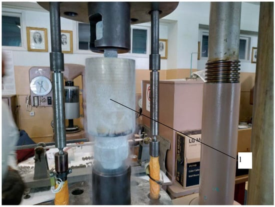
Figure 1.
General view of the mechanical testing setup for impulse energy introduction into materials, featuring chamber 1 for cryogenic cooling.
Mechanical tests were conducted on specimens (Figure 2) made of stainless steel X10CrNi18-8. This steel (analogous to AISI 302/EN 1.4310) belongs to the 300 series of stainless steels and is commonly recommended for spring manufacturing. Springs, in turn, operate under impact-oscillatory loading conditions.
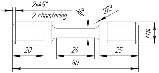
Figure 2.
Test specimen (dimensions indicated in mm).
The intensity of impulse energy introduction into the steel was controlled by sudden increases in dynamic strain εimp during the realization of DNP. In this context, εimp represents an integrated loading parameter that accounts for both the amplitude and temporal structure of the impulse. This approach also enabled the evaluation of DNP effects on subsequent deformation behavior under various loading conditions [19,20]. The range of εimp values applied to the steel was 0.06–2.69%.
To measure εimp in specimens subjected to IOL, an Optika B-510 MET optical microscope (New York Microscope Company, New York, NY, USA) was used, with an initial gauge length of 17 mm. The measurement accuracy was up to 0.002 mm. For subsequent static tensile testing, strain measurements were performed using a standard Class 0.5 extensometer manufactured at the Antonov Aircraft Production Plant (JSC "ANTONOV", Kyiv, Ukraine). The chemical composition of the steel was determined using the ElvaX Plus spectrometer (Elvatech Ltd., Kyiv, Ukraine).
The mechanical properties of the investigated steel and its chemical composition are presented in Table 1 and Table 2.

Table 1.
Mechanical properties of the steel X10CrNi18-8.
Table 2.
Chemical composition of the steel X10CrNi18-8, %.
Structural changes in the steel, both in its initial state and after pre-immersion in liquid nitrogen for 1 h followed by DNP treatment, were investigated using a JEOL-2100F transmission electron microscope (Jeol Ltd., Tokyo, Japan).
For X-ray diffraction (XRD) analysis, a BRUKER D2 Phaser diffractometer (Bruker AXS GmbH, Karlsruhe, Germany) equipped with a Cu-Kα1,2 radiation source (λ = 0.154 nm) was used. The diffraction patterns were processed using Match! Software (Version 4.0, Crystal Impact GbR, Bonn, Germany). As in [19], a combined analysis of TEM microstructures and selected area SAED patterns was performed for the tested specimens.
The test conditions, along with the limiting values of ultimate strength and strain of the steel under the specified conditions, are presented in Table 3.
Table 3.
Test conditions for steel X10CrNi18-8.
3. Research Results
3.1. Mechanical Results
Mechanical tests were performed in two stages in accordance with Table 1.
At the first stage, changes in the mechanical properties of the steel subjected to loading conditions 1 and 2, respectively, were evaluated (Table 3). Typical stress–strain curves are shown in Figure 3.

Figure 3.
Stress–strain curves of X10CrNi18-8 stainless steel at room temperature: (a) baseline steel (curve 23); (b) comparison of curves, where curve 9 corresponds to steel held in liquid nitrogen for 1 h (curve numbers indicate tested specimens).
Analysis of the obtained results (see Figure 3) shows that, for this steel, pre-immersion of specimens in liquid nitrogen for 1 h does not affect the static tensile stress–strain diagram at room temperature. It is worth noting that, for previously tested steel AISI 301, using the same methodology, pre-immersion in liquid nitrogen for 1 h significantly altered the mechanical properties of the base materials during subsequent static tensioning at room temperature [21].
In the second stage, the combined effects of cryogenic cooling and IOL of varying intensity applied in liquid nitrogen (loading condition 3, see Table 3) were studied for the steel subjected to subsequent static tensioning at room temperature.
To improve clarity of the obtained data (see Table 3), the test results are first presented graphically (Figure 4), and then in the form of stress–strain diagrams (Figure 5), which describe the behavior of selected specimens in comparison with the initial state. In these figures, the numbers correspond to the specimen identifiers.
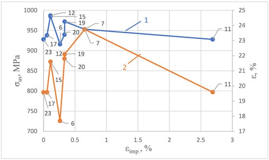
Figure 4.
Dependence of the limiting values of ultimate strength (curve 1) and ductility of steel X10CrNi18-8 (curve 2) on IOL of varying intensity pre-applied in liquid nitrogen.
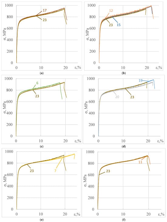
Figure 5.
Stress–strain diagrams of X10CrNi18-8 steel pre-subjected to complex loading (loading condition 3) and subsequent static tensioning: (a) curve 23 (static tensioning of baseline steel), curve 17 (εimp = 0.06%); (b) curves 12, 15 (εimp = 0.11%); (c) curve 6 (εimp = 0.26%); (d) curve 20 (εimp = 0.33%), curve 19 (εimp = 0.34%); (e) curve 7 (εimp = 0.65%); (f) curve 11 (εimp = 2.69%).
Analysis of Figure 4 and Figure 5 shows that the combined effects of cryogenic exposure and IOL of varying intensity on the mechanical properties of X10CrNi18-8 steel during subsequent static tensioning at room temperature are not as significant as those observed for previously studied steel AISI 301 [21]. However, the mechanical properties of the steel do undergo noticeable changes. These changes exhibit a characteristic wave-like pattern (see Figure 4 and Figure 5).
For instance, at εimp = 0.06%, the strain remains at the level of the initial state of the steel, 19.58%, while the ultimate strength increases slightly by 1%. At εimp = 0.11%, the strain increases by 10.3%, and the ultimate strength by 5.25%. It is also evident that at the same εimp = 0.11%, the effects on the mechanical properties during subsequent static tensioning are highly reproducible.
At εimp = 0.26%, the worst results were recorded: the strain decreased by 10.68%, and the ultimate strength dropped by 2.4%. As repeatedly noted in our previous work [21], each intensity level of impulse energy introduction during DNP leads to the formation of a new structural state in the material. Therefore, even minor differences in εimp can result in significant changes in mechanical properties.
Indeed, comparing the results for εimp = 0.33% and εimp = 0.34% shows that at εimp = 0.33%, the ultimate strength remains virtually unchanged compared to the initial state, while the strain increases by 11.3%. At εimp = 0.34%, both the ultimate strength and strain increase by 3.62% and 12.87%, respectively.
At εimp = 0.65%, the maximum increase in strain was recorded—21.24%, while the ultimate strength also rose by 2.69%. The most intriguing result was observed at εimp = 2.69%, where both the ultimate strength and strain remained at the level of the steel’s initial state. This indicates that the mechanical properties of the newly formed structure, resulting from complex loading (IOL in liquid nitrogen at εimp = 2.69% followed by static tensioning at room temperature), due to competing deformation processes at each stage, correspond to those of the original steel structure.
This is particularly interesting because εimp = 2.69% represents a nearly critical intensity of impulse energy introduction for this steel. At εimp > 2.7%, the structure of X10CrNi18-8 steel is unable to absorb the energy from IOL, and all tested specimens failed under dynamic loading. Therefore, studying such critical structural states in fractured specimens at εimp = 2.69% through further detailed metallophysical investigations is of both scientific and practical interest.
3.2. Metallophysical Results
As previously mentioned, the metallophysical investigation aimed to explain the changes in the mechanical properties of the steel after repeated static tensioning at room temperature, following the application of complex loading conditions at εimp = 0.11% and 2.69% (see Table 3).
To analyze the steel’s structure in its initial state and after testing at εimp = 0.11% and 2.69%, TEM micrographs and selected area SAED patterns were examined to identify structural differences. Representative TEM micrographs of the steel in its initial state are shown in Figure 6.
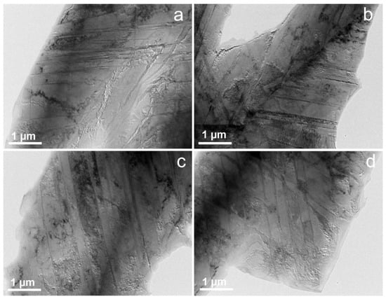
Figure 6.
Representative TEM micrographs of the steel in its initial condition: (a–d) Austenitic matrix interspersed with martensitic laths, observed in various regions of the specimen. These images depict the characteristic microstructural configuration of the material prior to the application of mechanical loading, highlighting the heterogeneous phase distribution and the presence of deformation-induced features.
Analysis of Figure 6 reveals that the microstructure of the steel in its initial condition is predominantly composed of the austenitic phase. TEM images demonstrate a high density of crystal lattice defects, including deformation twins, stacking faults, and dislocations, uniformly distributed throughout the austenitic matrix. These features are indicative of significant internal stresses and prior plastic deformation, contributing to the metastable nature of the phase. Figure 7 provides a more detailed characterization of the austenitic matrix. Selected area SAED patterns were obtained from regions consisting solely of the austenitic matrix (Figure 7c) and from areas containing both austenite and martensitic laths (Figure 7a). Figure 7b presents a bright-field TEM image of the analyzed region, marking the specific locations from which the diffraction data were acquired. Based on the SAED pattern in Figure 7a, dark-field TEM images were constructed using reflections indicated by yellow circles. Figure 7d corresponds to the austenitic phase, with the martensitic signal excluded, while Figure 7e highlights the morphology of the martensitic laths.
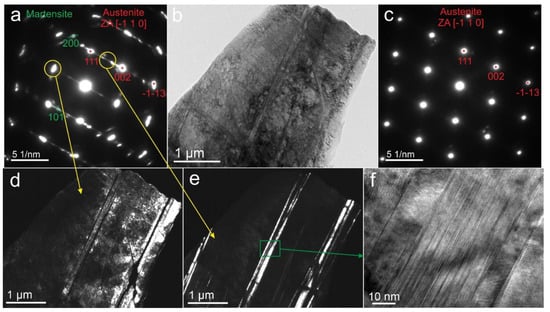
Figure 7.
TEM micrographs and corresponding SAED patterns of the steel in its initial condition: (a) SAED pattern acquired from a region containing both austenite (indexed in red) and martensite (indexed in green), illustrating the coexistence of phases. (b,d,e) Bright-field and dark-field TEM images showing the morphology and spatial distribution of martensitic laths embedded within the austenitic matrix. (c) SAED pattern obtained from a region consisting exclusively of the austenitic phase, confirming its crystallographic structure. (f) High-resolution TEM (HRTEM) image of a martensitic lath, revealing parallel stacking faults and twin boundaries, indicative of the complex defect structure formed during the martensitic transformation.
As shown in Figure 7d, the austenitic phase exhibits a high density of stacking faults and dislocations, reflecting its defect-rich nature. In contrast, Figure 7f displays a martensitic lath characterized by numerous stacking faults but an absence of visible dislocations, suggesting a distinct mechanism of defect formation and accommodation during the martensitic transformation.
As previously noted, variations in the intensity of impact-oscillatory loading (IOL) in liquid nitrogen lead to distinct mechanical responses of the investigated steel during subsequent static tensile testing at room temperature. A comprehensive metallophysical analysis was conducted for two structural states of the steel:
- -
- Following a preliminary IOL level corresponding to an imposed strain of εimp = 0.11% in liquid nitrogen, followed by unloading (an additional specimen, No. 13, was tested for this purpose).
- -
- Following an IOL level of εimp = 2.69% in liquid nitrogen, followed by monotonic tensile loading to failure (specimen No. 11). The preliminary IOL level of εimp = 0.11% is of particular interest, as it results in the highest ultimate tensile strength among all tested specimens during subsequent static loading. Moreover, the total elongation increases significantly by 10.3%.
Figure 8 presents TEM micrographs of specimen No. 13, corresponding to the structural state after IOL in liquid nitrogen at εimp = 0.11%. XRD analysis revealed the presence of approximately 1% martensitic phase in this specimen; however, TEM observations and the corresponding selected area SAED patterns show reflections exclusively from the austenitic phase. Compared to the initial state, the TEM images (Figure 8a–c) indicate a substantial increase in dislocation density, while the number of stacking faults has noticeably decreased. Figure 8d reveals deformation twins, visible as dark, parallel bands within the austenitic matrix.
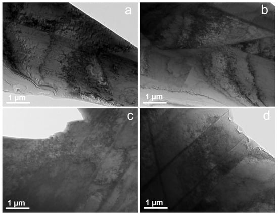
Figure 8.
Representative TEM micrographs of the steel after impact-oscillatory loading (IOL) at an imposed strain of εimp = 0.11% in liquid nitrogen (specimen No. 13). Panels (a–d) depict a microstructure predominantly composed of an austenitic matrix characterized by a high density of dislocations and stacking faults. These images illustrate the typical structural state of the material following preliminary low-temperature IOL.
The grain selected from specimen No. 13, shown in Figure 9a, was used to obtain the SAED pattern presented in Figure 9b. The diffraction pattern contains reflections corresponding solely to the austenitic phase. Upon tilting the grain to the [−2 −1 1] zone axis, dislocations become clearly visible (Figure 9c,d). Figure 9c illustrates the grain boundary region, where a high density of dislocations is observed both within the tilted grain and along the boundary itself, whereas the adjacent grain exhibits an almost negligible dislocation density. This contrast in dislocation distribution highlights the significant influence of local crystallographic orientation on the accumulation and spatial distribution of dislocations during low-temperature impact-oscillatory loading.
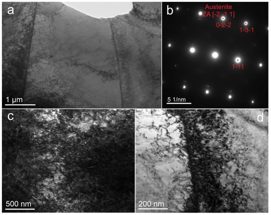
Figure 9.
TEM micrographs and corresponding SAED pattern of a local region in X10CrNi18-8 austenitic stainless steel pre-exposed to impact-oscillatory loading (IOL) in liquid nitrogen at an imposed strain of εimp = 0.11% (specimen No. 13). (a) Microstructure of the austenitic matrix exhibiting a high density of dislocations and deformation twins. (b) SAED pattern acquired along the [−2 1 1] zone axis, showing diffraction spots corresponding exclusively to the austenitic phase. (c) TEM image of the austenitic matrix showing a very high density of dislocations together with numerous stacking faults, forming a heavily deformed substructure (d) Pronounced dislocation accumulation observed along grain boundaries, indicating localized plastic deformation.
Figure 10 presents additional TEM micrographs and corresponding SAED patterns of the austenitic matrix in specimen No. 13. The diffraction patterns (Figure 10a,c), obtained from the grains highlighted in red, show reflections corresponding exclusively to the austenitic phase. The appearance of paired reflections near the main austenite spots indicates the presence of deformation twins within the austenitic matrix. The bright-field image (Figure 10b) illustrates the analyzed region and the locations where the diffraction patterns were obtained. Figure 10d,e show grains tilted to the zone axis, revealing dense dislocation structures and deformation twins. A high density of dislocations is observed both inside the tilted grains and near the grain boundaries.
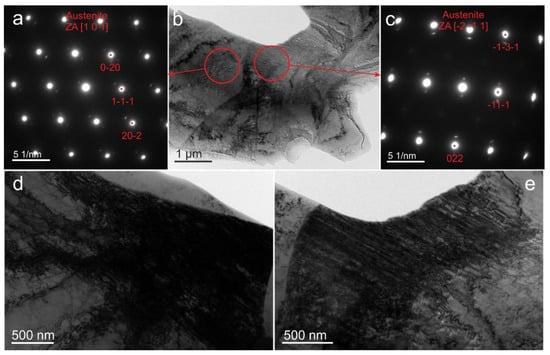
Figure 10.
TEM micrographs and corresponding SAED patterns of the austenitic matrix in X10CrNi18-8 steel after IOL in liquid nitrogen at εimp = 0.11% (specimen No. 13): (a,c) SAED patterns acquired from the grains highlighted in red; (b) Bright-field TEM image of the analyzed region, indicating the areas where the diffraction patterns were obtained; (d,e) Higher-magnification images of grains tilted to the zone axis, revealing dense dislocation structures and deformation twins within the austenitic matrix.
These results indicate that low-temperature IOL at εimp = 0.11% promotes the formation of deformation twins and a high density of dislocations within the austenitic matrix, while martensitic transformation remains negligible. Such microstructural features suggest that plastic deformation at this stage is primarily accommodated through dislocation slip and mechanical twinning [22,23].
Analysis of the TEM micrographs for specimen No. 11, subjected to impact-oscillatory loading (IOL) in liquid nitrogen at an imposed strain of εimp = 2.69% (Figure 11a–d), reveals a pronounced increase in the fraction of martensitic grains within the steel microstructure. Concurrently, the overall dislocation density is noticeably reduced compared to the previously observed state. The micrographs clearly indicate that, following IOL at εimp = 2.69%, martensitic transformation becomes the dominant structural mechanism. In this regime, plastic deformation within the austenitic matrix primarily proceeds through the formation of martensitic laths, rather than via conventional dislocation glide. This microstructural evolution signifies a transition from dislocation- and twinning-mediated plasticity to transformation-induced plasticity (TRIP) at elevated impact strain levels.
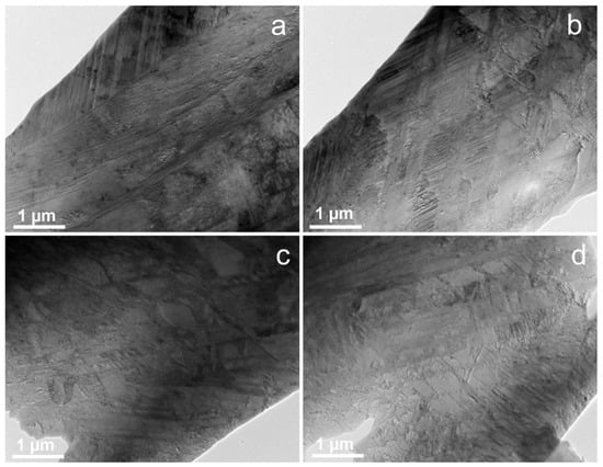
Figure 11.
Representative TEM micrographs of the steel after IOL in liquid nitrogen at εimp = 2.69% (specimen No. 11): (a–d) microstructure consisting of an austenitic matrix with numerous martensitic laths formed during low-temperature impact deformation.
Figure 12 presents TEM images and the corresponding SAED pattern of specimen No. 11, demonstrating the coexistence of austenitic and martensitic phases. The SAED pattern (Figure 12b) confirms the presence of diffraction spots corresponding to both austenite and martensite, indicating that a partial martensitic transformation occurred during impact-oscillatory loading in liquid nitrogen. Dark-field images (Figure 12a,c) reveal the morphology and distribution of martensitic laths within the austenitic matrix, while higher-magnification images (Figure 12d,e) show the internal substructure of both phases. Stacking faults are observed both within the martensitic laths and in the remaining austenitic matrix, which is typical for austenitic steels deformed at cryogenic temperatures. The well-developed martensitic regions and reduced dislocation density in the remaining austenite suggest that, at this strain level, the deformation is largely governed by stress-induced martensitic transformation rather than by dislocation slip or twinning [24,25].
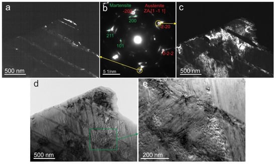
Figure 12.
TEM micrographs and corresponding SAED pattern of X10CrNi18-8 steel after IOL in liquid nitrogen at εimp = 2.69% (specimen No. 11): (a,c) dark-field TEM images showing the coexistence of martensitic laths and the austenitic matrix; (b) SAED pattern corresponding to austenite (red indices) and martensite (green indices) phase; (d,e) higher-magnification images revealing the morphology and internal substructure of both the martensitic laths and the surrounding austenitic matrix formed during low-temperature impact deformation.
Figure 13 presents additional TEM investigations of the steel microstructure for specimen No. 11, illustrating the coexistence of martensitic and austenitic phases. The SAED pattern (Figure 13b) contains reflections corresponding to both austenite and martensite, confirming the dual-phase structure of the steel after impact-oscillatory loading in liquid nitrogen. Dark-field images were constructed using the reflections highlighted in yellow in the SAED pattern: Figure 13c corresponds to martensite, while Figure 13d represents austenite. The diffraction pattern and the dark-field image (Figure 13c) clearly show a high density of stacking faults within the austenitic phase, whereas dislocations are almost absent in this region. The bright-field image (Figure 13a) reveals parallel martensitic laths formed within the austenitic matrix, while the dark-field images (Figure 13c,d) highlight their morphology and spatial distribution. The martensitic laths exhibit a well-defined parallel arrangement and sharp interfaces with the surrounding austenite. A comparative analysis of Figure 8, Figure 9 and Figure 10 and Figure 11, Figure 12 and Figure 13 shows that the microstructures of specimens No. 13 (εimp = 0.11%) and No. 11 (εimp = 2.69%) differ fundamentally, reflecting the transition from dislocation- and twin-mediated deformation to stress-induced martensitic transformation as the dominant mechanism.
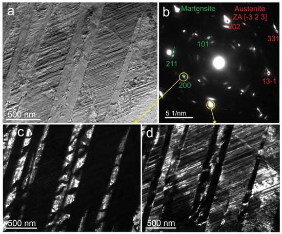
Figure 13.
TEM micrographs and corresponding SAED pattern of X10CrNi18-8 steel after impact-oscillatory loading (IOL) in liquid nitrogen at εimp = 2.69% (specimen No. 11): (a) bright-field image showing parallel martensitic laths formed within the austenitic matrix; (b) SAED pattern corresponding to both austenite (red indices) and martensite (green indices) phases; (c,d) dark-field TEM images illustrating the morphology, alignment, and distribution of both the martensitic laths and the surrounding austenitic matrix, selected from the diffraction spots marked in (b).
Following the TEM analysis, XRD measurements were carried out to quantitatively evaluate the phase composition of the steel after impact-oscillatory loading in liquid nitrogen. Figure 14 presents the XRD patterns of two X10CrNi18-8 steel specimens in different structural states. Specimens No. 13 and No. 11 correspond to samples pre-immersed in liquid nitrogen for 1 h and subsequently subjected to DNP at εimp = 0.11% and 2.69%, respectively. The obtained data confirm that the investigated steel has a dual-phase structure. The first phase corresponds to a face-centered cubic (FCC) austenite (space group Fm–3m) with a lattice parameter a = 0.359 nm, while the second phase corresponds to a body-centered cubic (BCC) martensite (space group Im–3m) with a lattice parameter a = 0.288 nm. Preliminary quantitative analysis indicates that the amount of austenite decreases from 99% in specimen 13 to 78% in specimen 11, whereas the volume fraction of α-martensite increases from 1% to 22%, respectively.
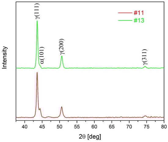
Figure 14.
X-ray diffraction patterns of austentic stanless steel X10CrNi18-8 in different structural conditions (see Table 3).
These XRD findings are in good agreement with the TEM observations, confirming the progressive development of martensitic transformation with increasing impact strain. A combined analysis of the diffraction and microscopic data demonstrates that the structural evolution of X10CrNi18-8 steel during cryogenic impact loading involves a gradual transition from a dislocation- and twin-dominated austenitic microstructure to a two-phase mixture of austenite and martensite, consistent with the stress-induced transformation mechanism.
4. Discussion
The initial tensile strength of X10CrNi18-8 steel, measured at 928 MPa, along with its relatively high ductility of 19.58%, indicates that the material is already significantly work-hardened—this is not a typical annealed state of X10CrNi18-8 steel. Such mechanical properties suggest either substantial cold working or a combination of strain hardening with deformation-induced transformation of austenite into α-martensite, accompanied by partial twinning.
Given the chemical composition of the steel (Cr = 17.39%, Ni = 9.13%, C = 0.138%, N = 0.076%), the austenitic phase is metastable. Therefore, the observed structural features in the initial state—namely, a mixture of high dislocation density, deformation twins, and a certain fraction of α-martensite—are consistent with expectations.
Following preliminary IOL at εimp = 0.11% in liquid nitrogen, the steel’s microstructure exhibits a significant increase in dislocation density and the emergence of deformation twins. These structural changes are responsible for the observed increase in tensile strength during subsequent static loading. It is likely that the contribution of martensitic transformation at such a low εimp level is minimal during further deformation at room temperature.
Metallophysical analysis also revealed a reduction in stacking fault density within the austenitic phase at εimp = 0.11%, which may have contributed to the enhanced ductility of the steel. Thus, even a relatively low-intensity IOL in liquid nitrogen (εimp = 0.11%) induces noticeable structural modifications that significantly affect the mechanical properties of the material.
To explain the nearly identical stress–strain diagrams observed for the steel in its initial state and after complex loading regime 3 (Table 3), corresponding to εimp = 2.69% (specimen No. 11), it is necessary to consider the key structural features of specimen No. 11. At higher IOL intensity (εimp = 2.69%) followed by static tension, the total martensite content in the microstructure increases substantially—up to 22%. Simultaneously, the dislocation density decreases, and numerous stacking faults are observed within the austenitic phase.
The formation of a significant fraction of the harder martensitic phase leads to the development of microcracks and other defects at the phase boundaries between austenite and martensite, resulting in elevated internal stresses. The excessive martensite content reduces the material’s ability to undergo uniform plastic deformation, which explains the decrease in ductility—from 23.74% at εimp = 0.65% to 19.59% at εimp = 2.69%. Moreover, the ultimate tensile strength does not increase due to the competing effects of internal defects.
Partial relaxation of internal stresses in specimen No. 11 after IOL and subsequent air tempering may reduce the initial work-hardening effect; however, brittle localized zones remain within the microstructure. The presence of a high density of stacking faults in the austenitic phase may also hinder plastic deformation of the matrix, thereby affecting the overall ductility of the steel.
The similarity in deformation diagrams between the initial state and the complex loading regime may be coincidental. Nevertheless, the trend observed as εimp approaches 2.7%, where the total martensite content reaches 22% and specimens fail under dynamic loading conditions, is potentially hazardous.
Similar results were obtained by the authors during testing of a dual-phase (α + β) high-strength titanium alloy VT23M under comparable loading conditions [22]. The VT23M alloy demonstrates high resistance to IOL in liquid nitrogen up to an imposed strain of εimp ≈ 0.6%. As εimp gradually increases to 0.6%, the alloy’s tensile strength remains nearly unchanged, while ductility decreases significantly. At εimp > 0.6%, the specimens fail under dynamic loading. Detailed structural analysis using physical methods revealed that the reduction in ductility is associated with the accumulation of defects in the more brittle α-phase. Upon reaching a critical defect concentration in the α-phase (εimp > 0.6%), the alloy fails under the specified dynamic loading regime.
5. Conclusions
For the first time, the influence of preliminary IOL of varying intensity directly applied in liquid nitrogen on the mechanical properties of X10CrNi18-8 stainless steel—with a relatively moderate initial strain level (~20%)—was evaluated during subsequent static tensile testing at room temperature. A distinct wave-like mechanical response of the steel was observed within the investigated range of imposed strain εimp = 0.06–2.69%. The scatter in ultimate tensile strength across all loading regimes was within 6.38%, while the variation in ductility reached up to 21.25%. At εimp > 2.7%, the steel specimens failed under dynamic loading conditions.
To explain the observed mechanical behavior within this specific range of preliminary energy input via IOL in liquid nitrogen, a detailed structural analysis was performed using physical characterization methods on selected specimens. A clear correlation was established between the steel’s structural state and its mechanical properties. Notably, as εimp approaches 2.7%, the total fraction of the more brittle martensitic phase in the steel microstructure reaches approximately 22%. Consequently, further increases in εimp result in the formation of a brittle structure incapable of absorbing additional impact energy.
It has previously been noted that X10CrNi18-8 steel is frequently used as a spring-grade stainless steel. Based on the findings of this study, it can be concluded that unexpected risks of sudden failure may arise even at relatively low strain levels when this steel is subjected to combined IOL and cryogenic cooling conditions.
The proposed methodology for assessing the influence of preliminary IOL of varying intensity directly in liquid nitrogen on the mechanical behavior during subsequent static tensioning may prove highly valuable for selecting the most promising stainless steels for critical cryogenic applications, particularly those operating under dynamic loading conditions during service.
Author Contributions
Conceptualization, M.C., A.P. and P.M.; methodology, M.C.; investigation, V.H., V.S., M.C., A.P., P.M., V.S., M.L., D.Y., P.S. and J.B.; formal analysis, A.P. and V.S.; funding acquisition, J.B.; writing—review and editing, V.H., V.S., M.C., A.P., P.M., V.S., M.L., D.Y., P.S. and J.B.; validation, P.M. and M.C.; All authors have read and agreed to the published version of the manuscript.
Funding
This research is the result of a project supported by project the VEGA Scientific Grant Agency “Possibilities of ap-plying laser additive technologies in the restoration of functional surfaces” (1/0597/23), the Cultural and Educational Grant Agency KEGA “Hybrid education of students for the current needs of the automotive industry” (024TUKE-4/2025), the Slovak Research and Development Agency “Innovative approaches to the restoration of functional surfaces by laser surface treatment” (APVV-20-0303) and “Integrity of protective multilayers under high-temperature exposure conditions” (APVV-24-0381). Maksym Lisnichuk acknowledges the financial support provided under the Next Generation EU through the Recovery and Resilience Plan for Slovakia under project No. 09I03-03-V04-00264.
Data Availability Statement
The original contributions presented in this study are included in the article. Further inquiries can be directed to the corresponding author.
Conflicts of Interest
The authors declare no conflicts of interest.
References
- Anoop, C.R.; Singh, R.K.; Kumar, R.R.; Jayalakshmi, M.; Prabhu, T.A.; Tharian, K.T.; Narayana Murty, S.V.S. A review on steels for cryogenic applications. Mater. Perform. Charact. 2021, 10, 16–88. [Google Scholar] [CrossRef]
- Savyasachi, N.; Reji, R.; Sajan, J.A.; Rafi, A. A review on the cryogenic treatment of stainless steels, tool steels and carburized steels. Int. J. Innov. Sci. Res. Technol. 2020, 5, 31–38. [Google Scholar]
- Sun, D.; Li, J.; Hao, X.; Wang, M.; Li, D.; Sun, X.; Yang, Z.; Wang, T.; Zhang, F. Effect of cold rolling and cryogenic treatment on the microstructure and mechanical properties of Fe- 32Ni alloy. Metals 2024, 14, 174. [Google Scholar] [CrossRef]
- Jamali, A.R.R.; Khan, W.; Chandio, A.D.; Anwer, Z.; Jokhio, M.H. Effect of cryogenic treatment on mechanical properties of AISI 4340 and AISI 4140 steel. Mehran Univ. Res. J. Eng. Technol. 2019, 38, 755–766. [Google Scholar] [CrossRef]
- Ye, C.; Suslov, S.; Lin, D.; Cheng, G.J. Deformation-induced martensite and nanotwins by cryogenic laser shock peening of AISI 304 stainless steel and the effects on mechanical properties. Philos. Mag. 2012, 92, 1369–1389. [Google Scholar] [CrossRef]
- Fedoriková, A.; Petroušek, P.; Kvačkaj, T.; Kočiško, R.; Zemko, M. Development of Mechanical Properties of Stainless Steel 316LN-IG after Cryo-Plastic Deformation. Materials 2023, 16, 6473. [Google Scholar] [CrossRef]
- Li, X.; Wei, Z.; Wang, X.; Yang, L.; Hao, X.; Wang, M.; Guo, M.; Guo, J. Effect of cryogenic temperatures on the mechanical behavior and deformation mechanism of AISI 316H stainless steel. J. Mater. Res. Technol. 2023, 22, 3375–3386. [Google Scholar] [CrossRef]
- Sohrabi, M.J.; Mirzadeh, H.; Sadeghpour, S.; Mahmudi, R.; Kalhor, A.; Rodak, K.; Kim, H.S. Remarkable cryogenic strength and ductility of AISI 904L superaustenitic stainless steel: A comparative study. Met. Mater. Trans. A 2024, 55, 4310–4317. [Google Scholar] [CrossRef]
- Fricke, L.V.; Gerstein, G.; Kotzbauer, A.; Breidenstein, B.; Barton, S.; Maier, H.J. High strain rate and stress-state-dependent martensite transformation in AISI 304 at low temperatures. Metals 2022, 12, 747. [Google Scholar] [CrossRef]
- Narkevich, N.; Vlasov, I.; Volochaev, M.; Gomorova, Y.; Mironov, Y.; Panin, S.; Berto, F.; Maksimov, P.; Deryugin, E. Low-Temperature Deformation and Fracture of Cr-Mn-N Stainless Steel: Tensile and Impact Bending Tests. Metals 2023, 13, 95. [Google Scholar] [CrossRef]
- Singh, D.; Yoshinaka, F.; Takamori, S.; Emura, S.; Sawagushhi, T. Breaking the strength-ductility trade-off in austenitic stainless steel at cryogenic temperatures: Mechanistic insights. J. Mater. Res. Technol. 2024, 33, 600–611. [Google Scholar] [CrossRef]
- Lee, I.-S.; Kim, S.-T. Investigation of Tensile and Impact Properties Associated with Microstructures of a Cast Austenitic High-Manganese Steel and CF3 Austenitic Stainless Steel for Cryogenic Application. Int. J. Met. 2025, 19, 3405–3419. [Google Scholar] [CrossRef]
- Kim, M.-S.; Lee, T.; Park, J.-W.; Kim, Y. Tensile and Fracture Characteristics of 304L Stainless Steel at Cryogenic Temperatures for Liquid Hydrogen Service. Metals 2023, 13, 1774. [Google Scholar] [CrossRef]
- Fernández-Pisón, P.; Rodríguez-Martínez, J.; García-Tabarés, E.; Avilés-Santillana, I.; Sgobba, S. Flow and fracture of austenitic stainless steels at cryogenic temperatures. Eng. Fract. Mech. 2021, 258, 108042. [Google Scholar] [CrossRef]
- Homayounfard, M.; Ganjiani, M.; Sasani, F. Damage development during the strain induced phase transformation of austenitic stainless steels at low temperatures. Model. Simul. Mater. Sci. Eng. 2021, 29, 045004. [Google Scholar] [CrossRef]
- Chausov, M.G.; Maruschak, P.O.; Pylypenko, A.P.; Berezin, V.B. Features of Deformation and Fracture of Plastic Materials Under Impact-Oscillatory Loading; LLC “Terno-graf”: Ternopil, Ukraine, 2018; 288p. (In Ukrainian) [Google Scholar]
- Nicolis, G.; Prigogine, I. Self-Organization in Non-Equilibrium Systems; Wiley Inter-Science: Hoboken, NJ, USA, 1977; ISBN 0-471-02401-5. [Google Scholar]
- Huang, M.; del Castillo, P.E.J.R.D.; van der Zwaag, S. Modelling steady state deformation of fcc metals by non-equilibrium thermodynamics. Mater. Sci. Technol. 2007, 23, 1105–1108. [Google Scholar] [CrossRef]
- Kestin, J. Thermodynamics of Plastic Deformation. In Patterns, Defects and Microstructures in Nonequilibrium Systems; NATO ASI Series; Walgraef, D., Ed.; Springer: Dordrecht, Germany, 1987; Volume 121. [Google Scholar] [CrossRef]
- Kerley, G.I.; Asay, J.R. The Response of Materials to Dynamic Loading. Int. J. Impact Eng. 1987, 5, 69–99. [Google Scholar] [CrossRef]
- Chausov, M.; Maruschak, P.; Pylypenko, A.; Shmanenko, V.; Lisnichuk, M.; Yudina, D.; Sovák, P. Changes in the mechanical properties and structural condition of stainless steel AISI 301 caused by the combined effect of impact-oscillatory loading and cryogenic cooling. Effects caused by holding specimens in liquid nitrogen for 1 h. Vacuum 2025, 240, 114541. [Google Scholar] [CrossRef]
- Chausov, M.; Hutsaylyuk, V.; Maruschak, P.; Pylypenko, A.; Karpets, M.; Shmanenko, V. Cryogenic Investigations into the Effect of Impact-Oscillatory Loading on Changes in the Mechanical Properties and Structural Condition of VT23M Two-Phase Titanium Alloy. Materials 2024, 17, 3913. [Google Scholar] [CrossRef]
- Kim, J.-K. In-situ TEM investigation of deformation mechanisms of twinning-induced plasticity steel. Mater. Charact. 2023, 196, 112583. [Google Scholar] [CrossRef]
- Das, A.; Sivaprasad, S.; Ghosh, M.; Chakraborti, P.; Tarafder, S. Morphologies and characteristics of deformation induced martensite during tensile deformation of 304 LN stainless steel. Mater. Sci. Eng. A 2008, 486, 283–286. [Google Scholar] [CrossRef]
- Narutani, T.; Olson, G.; Cohen, M. Constitutive flow relations for austenitic steels during strain-Induced martensitic transformation. J. Phys. Colloq. 1982, 43, 429–434. [Google Scholar] [CrossRef][Green Version]


Disclaimer/Publisher’s Note: The statements, opinions and data contained in all publications are solely those of the individual author(s) and contributor(s) and not of MDPI and/or the editor(s). MDPI and/or the editor(s) disclaim responsibility for any injury to people or property resulting from any ideas, methods, instructions or products referred to in the content. |
© 2025 by the authors. Licensee MDPI, Basel, Switzerland. This article is an open access article distributed under the terms and conditions of the Creative Commons Attribution (CC BY) license.