Abstract
This study joins a 20 mm thick 5000-series aluminum alloy using hot-wire insertion combined with narrow-gap laser welding to evaluate the feasibility and welding characteristics of this technique. The findings indicate that weld formation is primarily influenced by the laser energy density and material deposition rate. A strategy for improving weld beads is introduced incorporating a reoriented laser spot during the final pass on narrow-gap joints. This approach improves penetration and produces defect-free joints. The optimal processing conditions result in complete joint formation with four welding passes. Microstructural analysis reveals that the aluminum matrix morphology evolves according to the local thermal history during welding. Measurements show that the weld region is slightly harder than the base metal, whereas slightly lower hardness is observed at the fusion line and inter-pass boundaries, which correlates with the microstructure result.
1. Introduction
Hydrogen is a promising energy carrier because of its environmental benefits [1,2,3,4,5]. Among the various storage methods, liquid and pressurized hydrogen vessels play a crucial role in transportation, aerospace, and energy applications [2]. These vessels must withstand extreme conditions, including cryogenic temperatures for liquid hydrogen (−253 °C) and high pressures in gaseous storage [1,2]. Ensuring structural integrity, thermal efficiency, and weight optimization is critical in designing hydrogen storage systems.
Aluminum alloys have gained significant attention for hydrogen vessel applications because of their favorable properties [3]. Their high strength-to-weight ratio reduces the overall mass of storage systems, which is particularly beneficial for aerospace and automotive applications where weight savings improve fuel efficiency. Additionally, aluminum alloys offer an advantage in the manufacture of storage tanks because of their excellent plastic formability. More importantly, aluminum alloys maintain good mechanical performance at cryogenic temperatures, making them suitable for liquid hydrogen containment. Al-Mg aluminum alloy A5083 with under around 5% Mg content has a very small hydrogen embrittlement property compared with some ferrous materials and high-strength aluminum alloys [6].
In the assembly of hydrogen storage vessels, welding plays a crucial role in ensuring high efficiency and quality, both of which are essential for the long-term reliability of the vessel’s service cycle [1,4,5]. This paper focuses on implementing a narrow-gap design and hot-wire insertion in the laser welding process to enhance weld integrity and performance [7,8,9]. The narrow-gap design offers several advantages, including reduced weld volume, which minimizes material consumption, residual stress, and welding shrinkage. The narrow-gap groove design also improves weld quality by reducing distortion and optimizing penetration depth. Hot-wire insertion further optimizes the welding by preheating the filler wire, which increases deposition rates and improves fusion efficiency without an increase in heat input. Moreover, a review of hot-wire insertion has suggested that heating the wire almost to melting temperature reduces the external heating required for uniform welding formation and, in some cases, leads to greater deposition under controlled heating than in the conventional cold-wire process [10,11,12,13,14]. This method enhances process stability, reduces porosity, and allows for better control over the weld microstructure. By integrating these advanced techniques, this study aims to improve the overall welding efficiency and mechanical performance of hydrogen vessels, ensuring their safe and long-term operation.
This paper explores the feasibility of laser-welding aluminum alloys with narrow-gap design and hot-wire insertion. The three main parts of this study are weld formation in aluminum alloy narrow-gap joints, optimizing the welding process to improve beads, and evaluating aluminum alloy joints fabricated by hot-wire narrow-gap welding. This experimentally based study is essential for advancing joining technology and ensuring safety and efficiency in cryogenic vessel systems.
2. Materials and Methods
The aluminum alloy JIS A5083-O with 20 mm thickness was used as the base material. This alloy has high corrosion resistance, excellent mechanical properties, and suitability for cryogenic applications [2,3,4,5]. AWS ER 5183-WY aluminum alloy wire with a 1.6 mm diameter was used as the filler material. This material provides high strength and good weldability, making it ideal for structural applications requiring superior ductility and toughness. Table 1 presents the chemical compositions of the materials used.

Table 1.
Chemical compositions of the base material and filler metal.
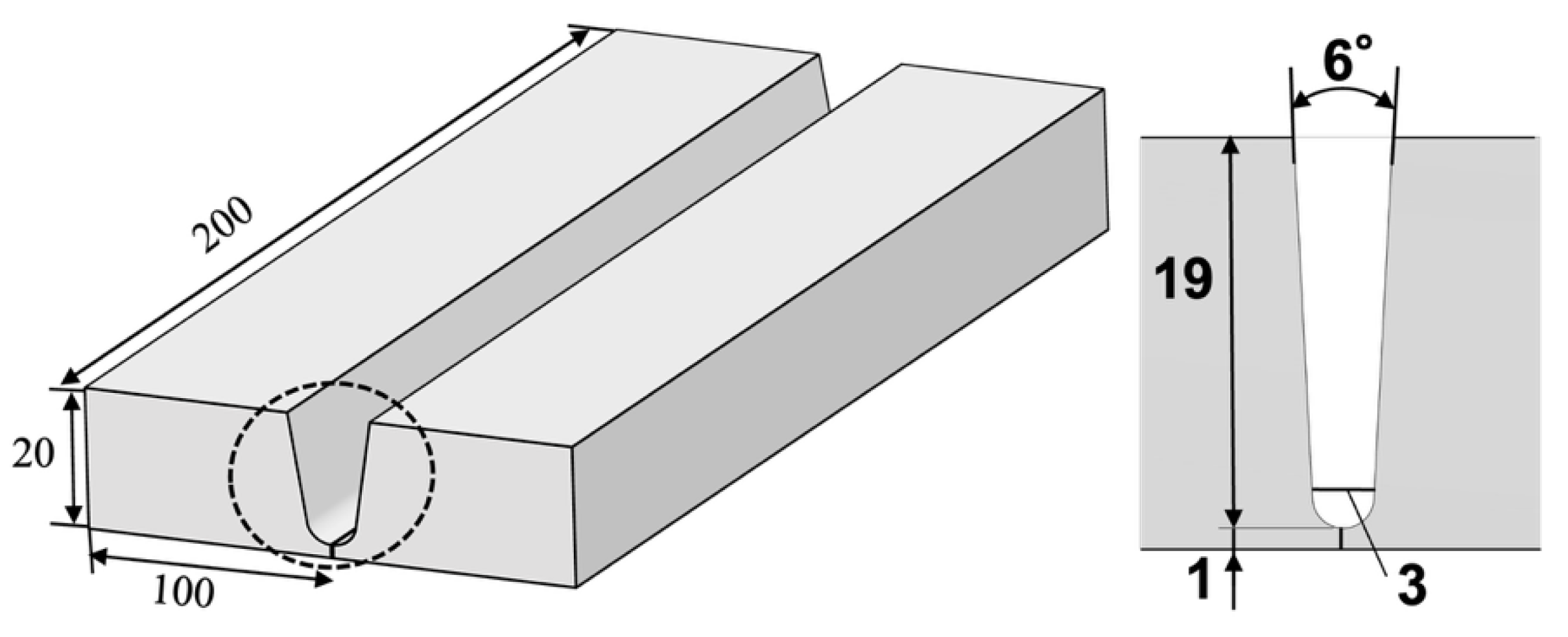
The specimen and narrow-gap groove dimensions are presented in Figure 1. The bottom gap and total groove angle are 3.0 mm and 6°, respectively. The groove was made by machining, and degreasing with acetone was performed before welding. This design minimizes the weld volume, reducing material consumption and residual stress while enhancing the welding efficiency [14,15,16,17,18]. Combined with advanced welding techniques, the narrow-gap approach is expected to improve weld quality by reducing distortion and porosity [17,18].
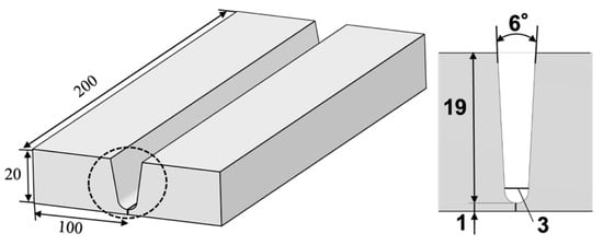
Figure 1.
Specimen and narrow-gap groove dimensions in dashed line section.
The welding process in this study used a diode laser as the main heat source with a peak power of 6 kW and a wavelength range of 900–1080 nm. The optical setup was configured to achieve a rectangular focal spot with a width of 1.6 mm and length of 6.0 mm, ensuring efficient energy distribution during welding. The experimental setup is presented in Figure 2. A weaving laser head was integrated into the optical system, enabling the laser beam to oscillate along a single axis, which enhances beam control and stability during welding. This study used the trapezoidal weaving function shown in Figure 3, featuring a peak-to-transition ratio of 2:3 in the gap width direction. Compared with conventional sine-wave oscillation, this function allows the laser beam to remain longer at both groove edges of the narrow-gap joint, improving energy absorption and fusion efficiency on both bevel surfaces [14]. This technique has demonstrated significantly improved penetration at the groove surfaces, contributing to enhanced weld quality in narrow-gap laser welding.
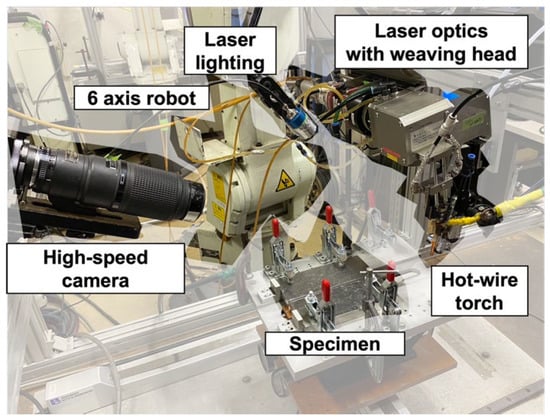
Figure 2.
Experimental setup.
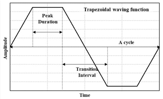
Figure 3.
Weaving waveform of the laser beam in the gap width direction.
The hot-wire heating system in this study used a pulse power source to preheat the filler wire, enhancing deposition efficiency and welding stability. The electrical configuration consisted of a positive-polarity connection for the feeding torch (wire) and a negative-polarity connection for the working table (base material). A pulse current with a frequency of 100 Hz and a 50% duty cycle was used. The pulse waveform was configured with the base current maintained at 0 A for filler wire melting stability. A high-speed camera and 808 nm laser light were used to observe molten pool formation and filler wire melting. A band-pass filter with an 810 nm wavelength was selected to match the laser wavelength, and it was attached to a high-resolution magnifying lens.
In the first part of this study, welding experiments were conducted to analyze the effect of key process parameters on weld bead formation in hot-wire laser welding of aluminum alloy narrow-gap joints. Table 2 lists the experimental conditions consisting of the key parameters for optimization, and Figure 4 presents the configuration for laser beam irradiation and filler wire insertion. The filler wire was inserted from the back of a molten pool. The study varied the laser power within a range of 5.0–6.0 kW, the wire feeding speed between 1.96 and 4.11 m/min, and the total weaving width from 3.00 to 8.54 mm. Forty-eight sets of conditions were tested to systematically evaluate the influence of these parameters on narrow-gap weld formation. By optimizing these variables, the study aimed to enhance penetration depth, bead uniformity, and overall weld quality in aluminum alloy narrow-gap welding.
Table 2.
Experimental conditions.
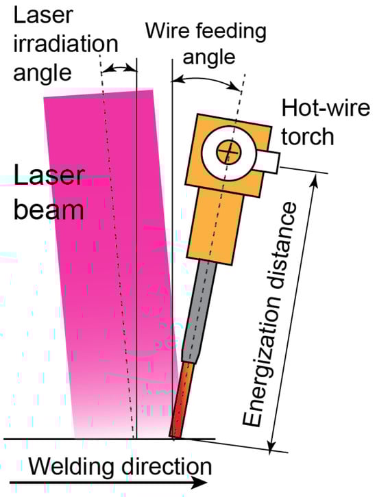
Figure 4.
Diagram of hot-wire feeding and energization torch showing laser irradiation and filler wire feeding positions.
In the second part, the study introduced a reoriented laser spot and laser spot weaving along the welding direction on the final pass in narrow-gap joints to improve bead formation by optimizing energy distribution and fusion. The size of the rectangular laser beam spot was maintained at a 6.0 mm width and 1.6 mm length. For welding up to before the final layer (the third layer), the optimal conditions obtained in the first step were used.
In the next part, the joints fabricated using the optimized conditions in the previous investigations were evaluated to assess hardness and microstructure. Sample preparation involved sectioning the welded specimens, followed by grounding with progressively finer abrasive papers, polishing with alumina or diamond suspension to achieve a mirror-like surface, and etching with Tucker’s reagent to reveal the microstructural details. Hardness was measured in the weld region and fusion boundary region. The hardness was tested with a load of 9.8 N for a dwell time of 12 s along a line from the weld center to the heat-affected zone and base metal, ensuring comprehensive coverage of the transition zones.
The microstructures of the weld metal and boundary region were examined using optical microscopy, scanning electron microscopy (SEM), and electron backscatter diffraction (EBSD). For SEM and EBSD sample preparation, the welded specimens were sectioned perpendicularly to the weld direction and mechanically polished following standard metallographic procedures. The SEM sample was prepared using chemical etching with Tucker’s reagent, which enhanced grain boundary visibility in the aluminum alloy. This preparation allowed for a detailed examination [19] of grain morphology and potential defects, such as porosity or microcracks. Similarly, the EBSD sample underwent final surface polishing with a 0.5 µm oxide suspension to further enhance grain boundary visibility, enabling a detailed analysis of crystal morphology.
3. Results and Discussion
3.1. Effects of Process Conditions on Weld Bead Formation
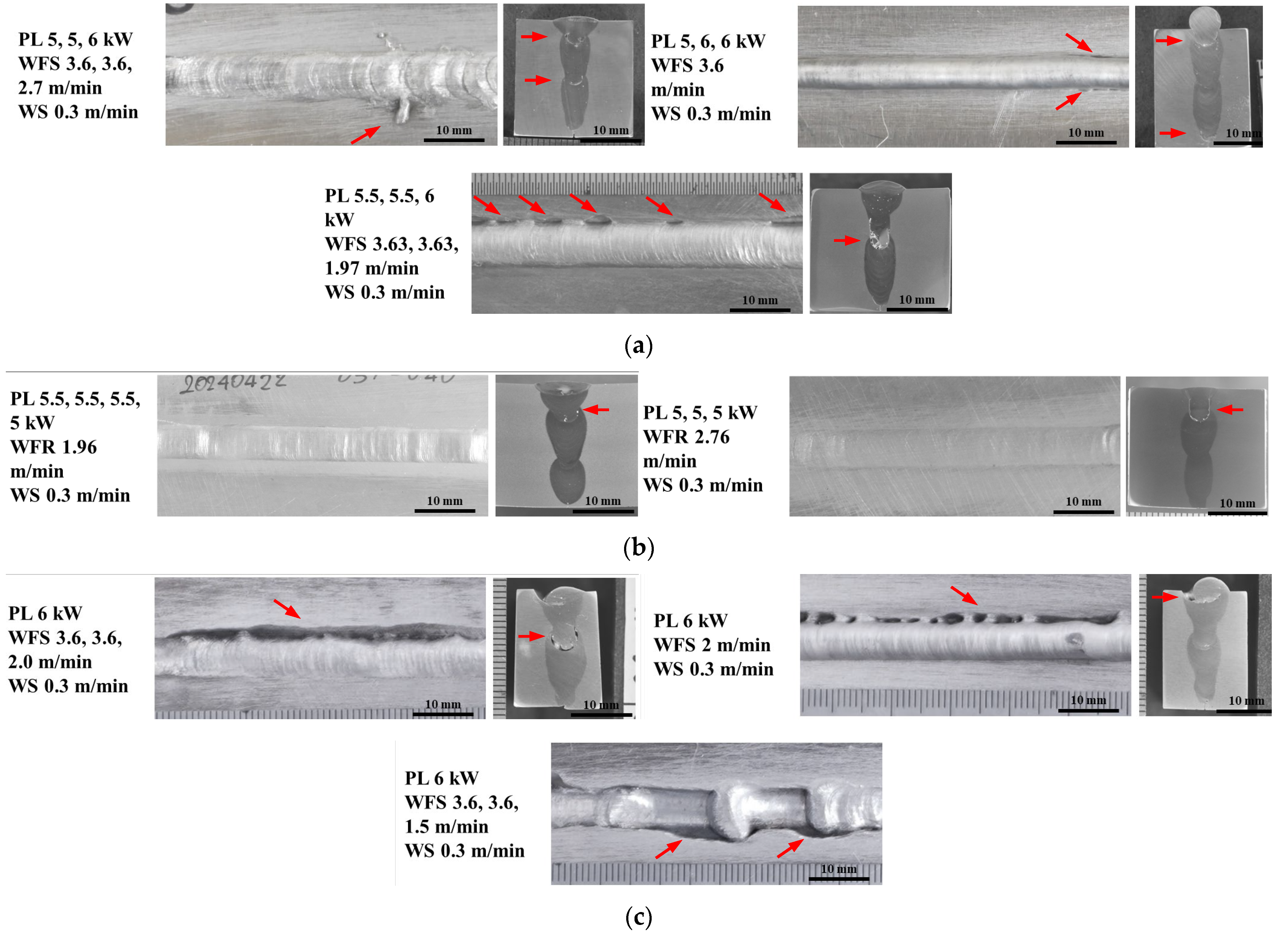
Previous studies have reported that bead characteristics in laser-welded aluminum alloys are significantly influenced by the energy distribution and filler material deposition [20,21,22,23,24]. Therefore, the three main welding parameters, which were the laser power, wire feeding rate, and total weaving width, were varied. The bead appearance and cross-section were obtained to classify and analyze the weld bead quality. The results revealed three scenarios of bead formation during hot-wire laser welding on aluminum narrow-gaps: (a) lack of fusion and insufficient melting, (b) suitable melting and proper bead formation, and (c) excessive melting. These are presented in Figure 5. The laser powers for each pass are indicated in Figure 5 as “PL 5, 5, 6 kW”, which means 5, 5, 6 kW laser power used for the 1st to 3rd passes, respectively. The details of the three bead formation scenarios were as follows:
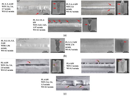
Figure 5.
Appearances and cross-sections of three classes of weld beads: (a) lack of fusion and insufficient melting, (b) suitable melting and proper bead formation, and (c) excessive melting. Red arrows indicate defects.
Figure 5a shows the results with lack of fusion and insufficient melting. The bead appearing on the top side shows residual filler wire without complete melting and incomplete fusion along the groove edge. The cross-section shows lack of fusion (penetration) at the intermediate layer bottom on the top side of the previous weld layer. In some cases, there are overlaps and holes on the top surfaces of the weld beads caused by relatively low heat and a non-bridging molten pool. This improper weld bead formation is thought to be caused by an improper combination of relatively low laser power and high wire feeding speed.
Figure 5b shows the results with suitable melting and bead formation. The top side shows uniform fusion and proper weld bead formation. The cross-section shows almost complete penetration. This proper weld bead formation is thought to be obtained through a proper match between the laser power and wire feed speed. However, a small lack of fusion is seen at the bottom region of the final layer. The adequate process window of the Deposition volume VS Laser power density is predicted as 4000~6000 mm3/min of the deposition volume and 210~310 W/mm2 of the laser power density for this welding process, which employs a diode laser with a rectangle beam combined with a weaving head, hot-wire insertion method, and 3 mm narrow-gap joint configuration.
Figure 5c shows the results with excessive melting. Beads show excessive melting, and several deep undercuts are observed along the groove edge on the top weld bead. In some cases, a non-uniform humping bead is also observed, which is thought to be caused by irregular transfer of filler wire into the molten pool. The cross-section reveals excessive melting in the upper region of each layer, and asymmetrical and irregular penetration. This improper weld bead formation is thought to be caused by an improper combination of relatively high laser power and low wire feeding speed. In addition, a total weaving width that is too large compared with the groove gap on the top surface might cause unstable and excessive melting of the edge of the groove top.
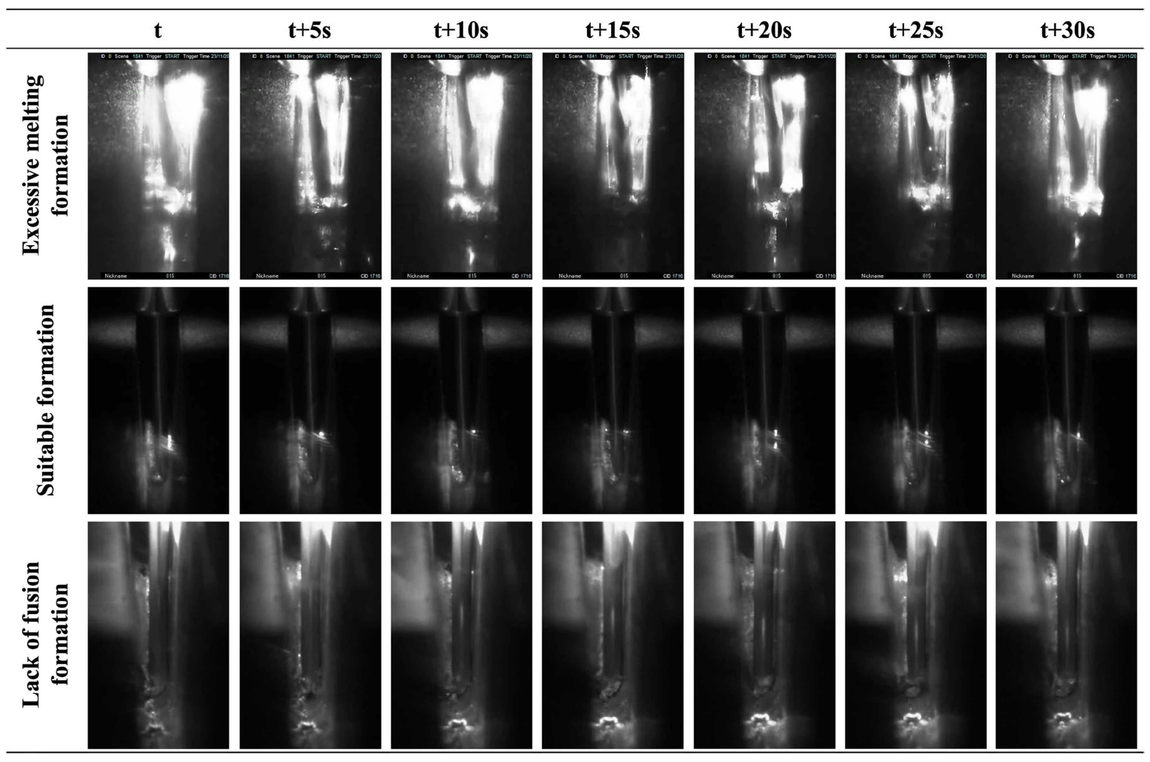
Figure 6 shows the high-speed camera images of filler wire melting and molten pool formation captured from the top side of the groove in the three cases during 30 s. The images in the middle row show stable filler wire melting and suitable molten pool formation. The filler wire tip melts properly and melted material transfers smoothly into the molten pool. As a result, the wire tip position and molten pool shape in the images hardly change within 30 s, and very stable welding is observed.

Figure 6.
High-speed images during welding in three cases.
The images in the bottom row show insufficient filler wire melting and the wire tip poking into the molten pool bottom. Only a very small molten pool forms, and solidification is observed just behind the wire feeding position. As a result, there is a lack of fusion and insufficient melting.
The images in the upper row show excessive wire heating and melting. The wire becomes too soft and hangs down, and then the wire insertion position shifts forward in the welding direction. Frequent fusing of the wire tip and spherical melt formation at the wire tip are also observed. As a result, unstable melted filler material transfers from the wire tip into the molten pool, and a non-uniform humping bead forms.
Several articles have reported the effects of the welding conditions [22,23,24,25,26,27,28,29] on bead formation. The formations of the molten pool and bead during laser welding of aluminum alloys are strongly related to the temperatures of the base metal, filler metal, and molten pool. On the basis of calculations [25,27,28] and experimental findings [22,23,28,29] from multiple studies, it has been concluded that the laser power, wire feed speed, and travel speed significantly influence the thermal profile of both the base material and weld pool during laser welding of aluminum alloys. It has also been shown that temperature variations directly affect molten pool formation, weld bead formation, weld bead quality, the geometric characteristics of the weld bead, and the mechanical and metallurgical properties of the welded joints.
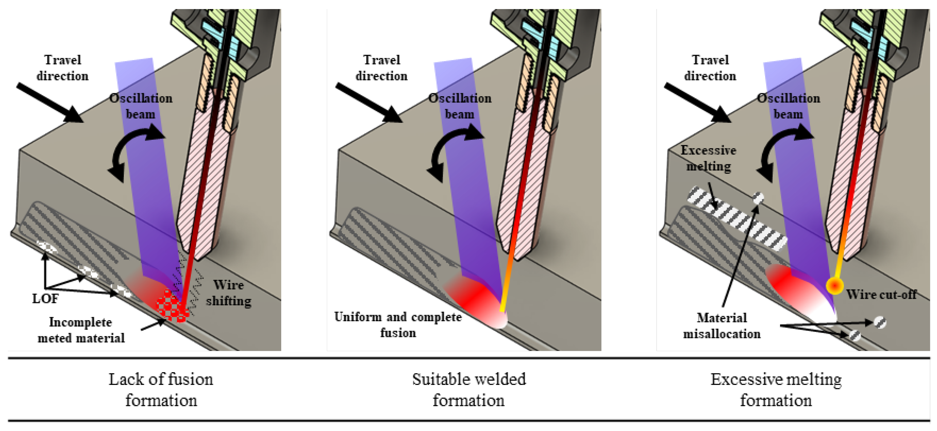
The observed bead appearances, cross-sections, and in situ images during welding in this study show that welding phenomena and bead formation are influenced by three major variables: laser power, wire feeding rate, and total weaving width. Figure 7 illustrates the three cases of bead formation during hot-wire laser welding of aluminum narrow-gap joints.
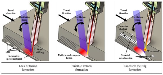
Figure 7.
Illustrations of welding phenomena and weld bead formation in three cases.
The hot-wire system feeds the filler wire heated to slightly below its melting point, and then the heat input to the laser-irradiated area melts the filler wire to form a molten pool during welding. When a suitable combination of laser power, wire feeding rate, and total weaving width are used, the filler wire tip melts properly just on the molten pool front, and then the molten pool forms smoothly and stably with an adequate size and temperature, as shown in the center of Figure 7. When relatively low heat is input with an inappropriate combination of low laser power and high wire feeding rate, the filler wire tip does not melt properly and sticks to the molten pool bottom, and then the molten pool forms with too small a size and too low a temperature, as shown in the left diagram of Figure 7. When relatively high heat is input with an inappropriate combination of high laser power and low wire feeding rate, the filler wire tip is heated excessively and fuses (cuts off) frequently, and then the molten pool forms with high temperature, as shown in the right diagram of Figure 7. In addition, excessive penetration (melting) of groove surfaces occurs, and an uneven humping bead is produced.
3.2. Improvement of Bead Formation on Final-Pass Welding by Laser Spot Reorientation
Beads of good quality were obtained in the groove by optimizing the welding conditions with a proper combination of laser power and filler wire feeding speed. However, there were still problems of defect formations during final-pass welding, such as excessive melting at the edges on the groove surface, undercuts, and lack of fusion. Therefore, improvement of bead formation in final-pass welding was investigated through laser spot reorientation.
The laser spot orientation and weaving direction were changed during final-pass welding, which was different from the previous internal passes. Specifically, the wider side of the laser spot was reoriented perpendicularly to the welding direction, and the laser spot was weaved in the welding direction. Several studies [30,31] have demonstrated that reducing the oscillation width or increasing the laser power density directly enhances the penetration depth in aluminum welding. Laser spot reorientation and weaving in the welding direction with a smaller weaving width are expected to reduce the heat input to both edges of the groove surface, thus preventing excessive melting, and to increase the heat input to the bottom in the final pass, thus preventing lack of fusion during the final pass.
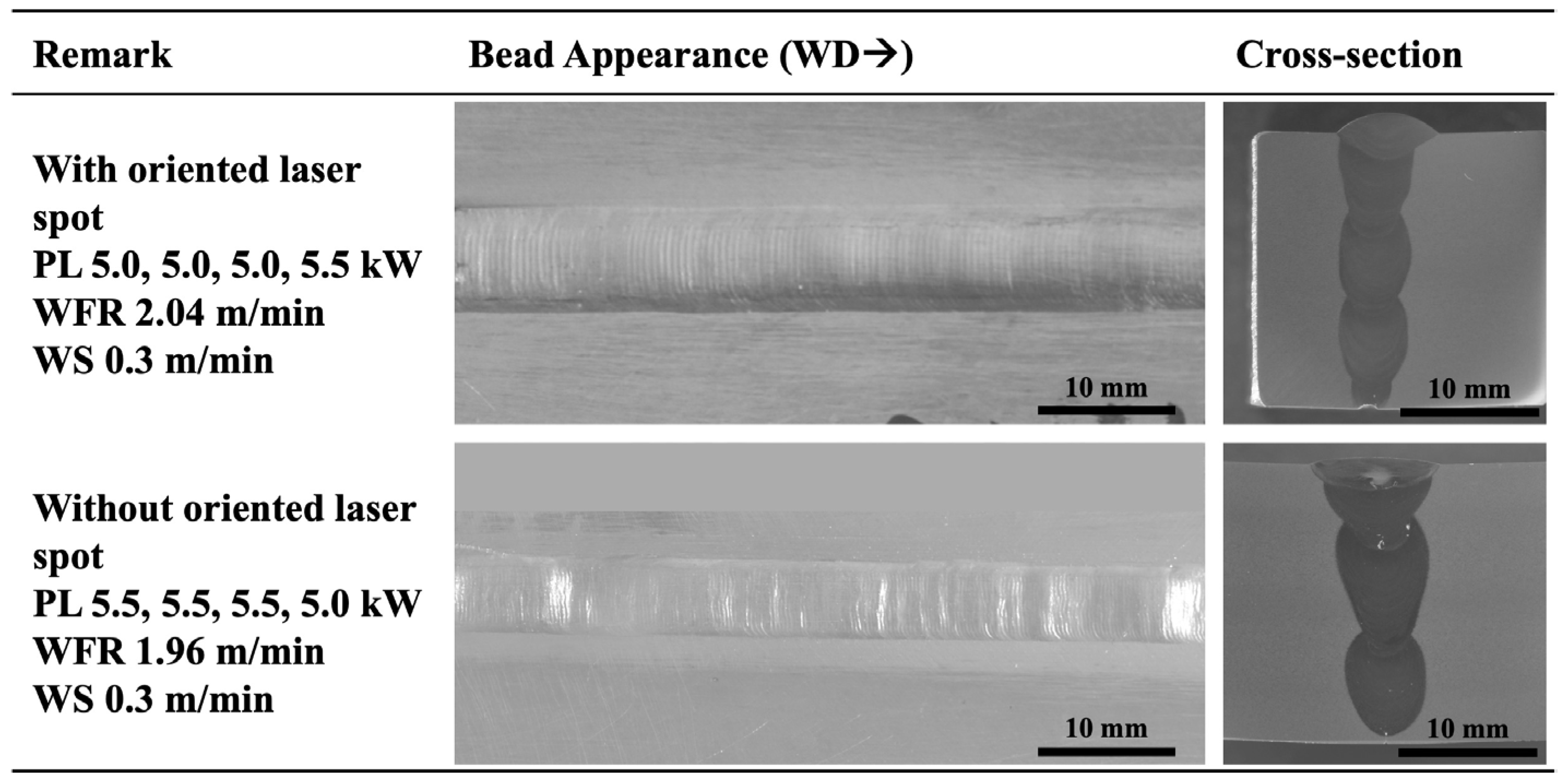
Figure 8 shows the bead appearances and cross-sections of welded joints fabricated using laser spot reorientation. Improved bead formation is seen without defects such as undercuts. Cross-sections also show sufficient penetration at the bottom of the final pass without defects, such as lack of fusion with the previous pass surface. The results are comparable to those reported in studies [31,32] using similar techniques to enhance the penetration depth in aluminum laser welding. In addition, laser spot weaving in the welding direction avoids excessive melting at the groove edges on the surface. These results indicate that reorienting the laser spot effectively enhances penetration, bead uniformity, and avoidance of defect formation during narrow-gap welding of an aluminum alloy joint.

Figure 8.
Weld bead appearances and cross-sections with laser spot reorientation.
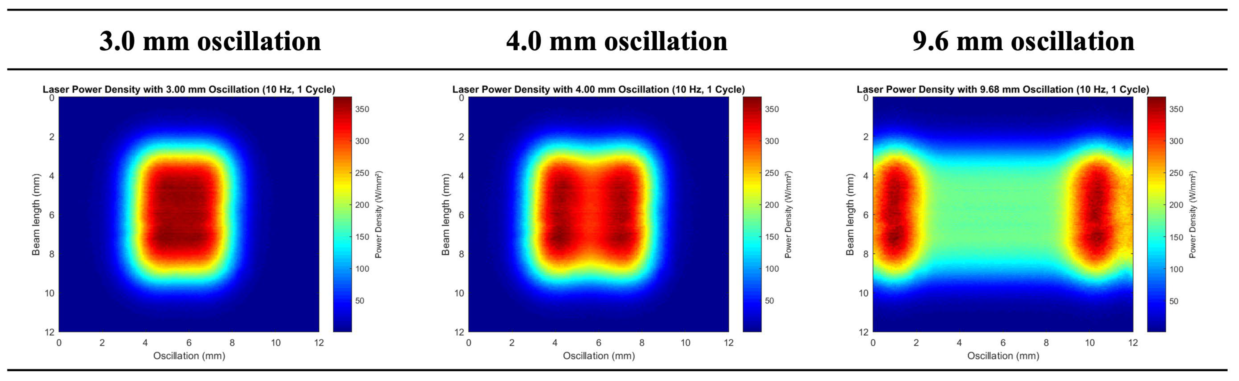
Figure 9 shows the laser energy distributions irradiated in one cycle oscillation using the trapezoidal weaving pattern as indicated in Figure 3 under three weaving width conditions, 3 mm, 4 mm, and 9.6 mm when the laser power is 5 kW. The high energy density around 300 W/mm2 can be seen widely in the center region under the 3 mm weaving width condition. The high energy density area separates into two regions when the weaving width becomes wider at 4 mm; however, the energy density in the center region still stays around 300 W/mm2. The high energy density in the center region and both sides achieves sufficient fusion at the bottom and side groove surfaces of each layer. When the weaving width becomes 9.6 mm, the energy density at both side regions still retains a high value over around 300 W/mm2, but the energy density in the center region decreases dramatically. This energy distribution results in insufficient fusion at the bottom of the upper layer and excessive melting at both edges of the weld bead. The reoriented laser weaving in the welding direction improves the energy distribution on the final pass and achieves high energy density at the groove center and adequate energy density at both groove edges. As a result, the sound bead can be obtained with sufficient fusion at the groove bottom and sound melting at both sides of the weld bead without any defects.
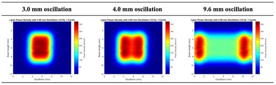
Figure 9.
Laser energy distributions in one cycle with trapezoidal weaving pattern.
3.3. Microstructure Observation of Fabricated Narrow-Gap Joint
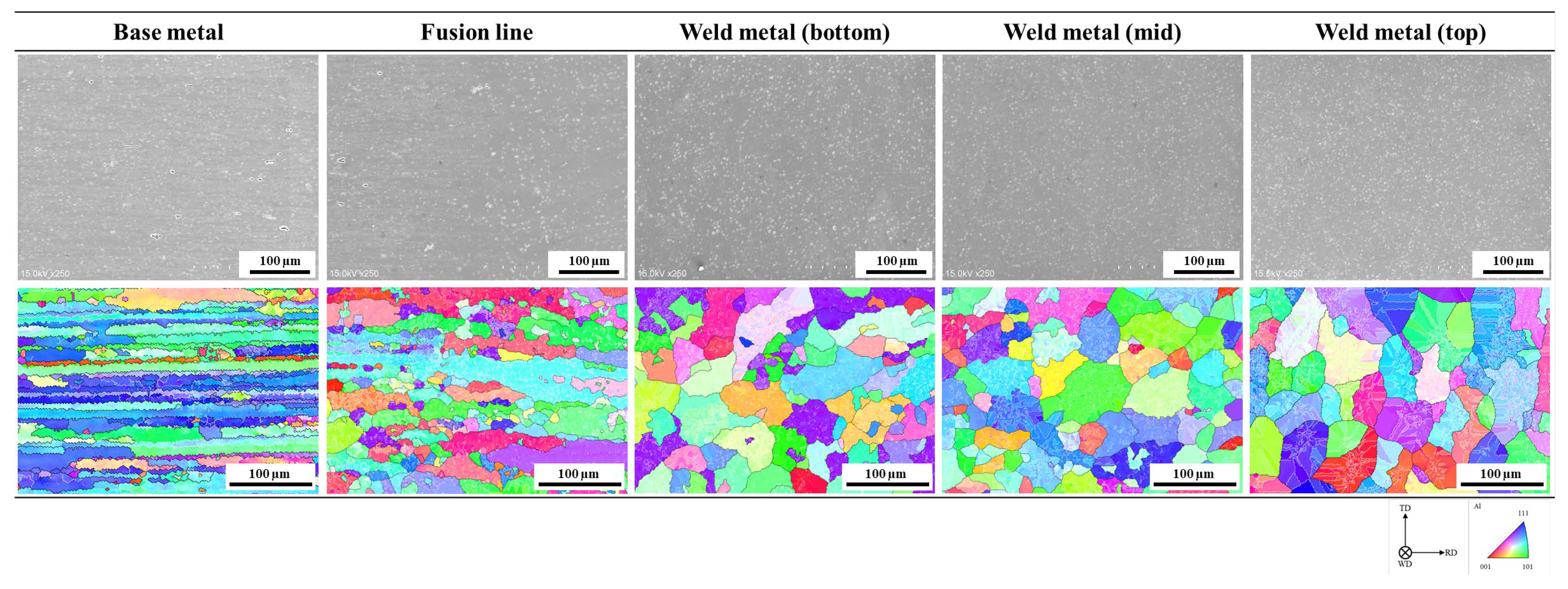
The microstructure and crystallographic observations of the base metal, fusion line, and weld metal regions in the fabricated joint were performed by SEM and EBSD, as shown in Figure 10. In the base metal region, large and elongated grains were observed, with randomly distributed secondary phases located along the grain boundaries [25].
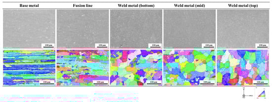
Figure 10.
Microstructures and EBSD results of fabricated narrow-gap joint.
In the weld metal region, fine secondary-phase particles, which are randomly distributed along the grain boundaries of the aluminum matrix phase, and equiaxed grains are observed throughout the weld. EBSD analysis also revealed random grain orientations due to low thermal gradients and rapid cooling. The grain morphology observed in the weld metal is relatively similar to that reported in several studies [25,29]. This similarity suggests that the thermal conditions and solidification behavior in this study align with previously documented microstructural evolution in aluminum laser welding.
At the fusion boundary, the microstructure exhibited a transition between the base metal and weld metal morphology. SEM analysis of the base metal near the fusion line showed a structure similar to that of the original base metal, but with slightly larger grains due to localized heat exposure [31]. EBSD analysis revealed small equiaxed grains near the elongated grain boundary, indicating nucleation from thermal cycling. This localized recrystallization results from sub-grain growth and dynamic recovery in the heat-affected zone (HAZ) [33,34,35,36]. In the weld metal near the fusion line, the microstructure transitioned into a columnar grain structure, typical of directional solidification under high thermal gradients and rapid cooling. The absence of equiaxed grains suggests insufficient nucleation, leading to preferred grain growth along the heat extraction path [31,33,34].
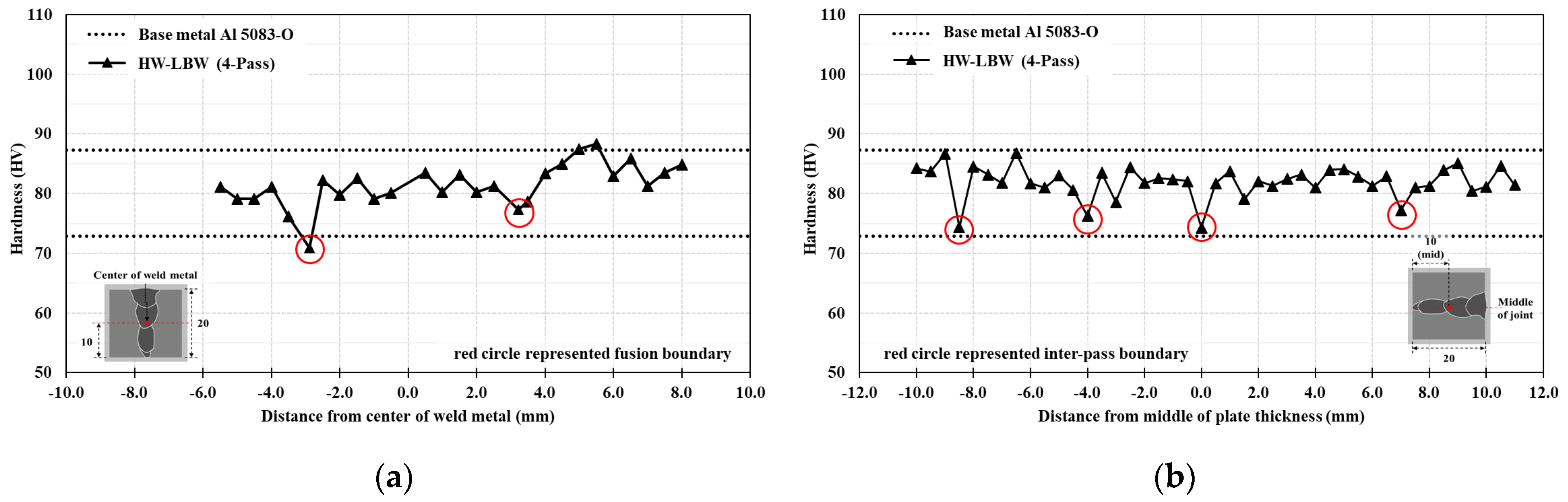
3.4. Hardness Distributions of Fabricated Narrow-Gap Joints
The Vickers hardness distributions were evaluated along the horizontal direction from the base metal to the weld metal at the joint center, and along the vertical direction at the center of the weld metal, as shown in Figure 11. The base metal (Al 5083-O) exhibits an average hardness of 80.1 HV with a standard deviation of 3.6 HV, while the weld metal has an average hardness of 81.9 HV with a standard deviation of 2.7 HV. This result indicates that the weld metal retains a hardness comparable to that of the base metal and achieves minimal softening through the low heat input of hot-wire laser welding. In the horizontal direction, localized reductions in hardness are observed at the fusion boundary [36,37]; however, the widths of the hardness drop regions at the fusion boundaries are extremely narrow.
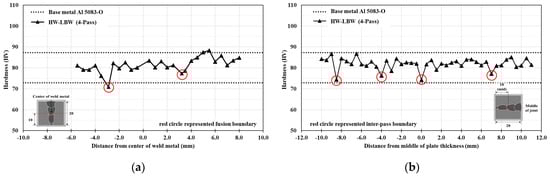
Figure 11.
Vickers hardness distributions of fabricated narrow-gap joints: (a) overall regions in the horizontal direction, and (b) weld metal regions in the vertical direction.
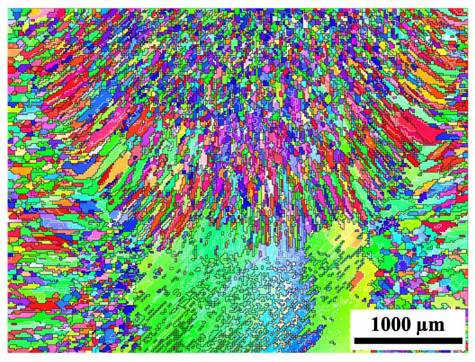
In the vertical direction, the hardness of the weld metal from the bottom to the top of the joint remains comparable to that of the base metal. Notably, localized reductions in hardness are observed at four inter-pass boundaries. These hardness reductions are due to thermal cycling effects during successive weld passes; however, all widths of the hardness drop regions at the four inter-pass boundaries are extremely narrow. These localized reductions in hardness occurred at the boundaries of the weld passes, since the top side region of the internal previous pass was subjected to a reheating process by the next welding pass and the grains slightly grew, as shown in Figure 12.
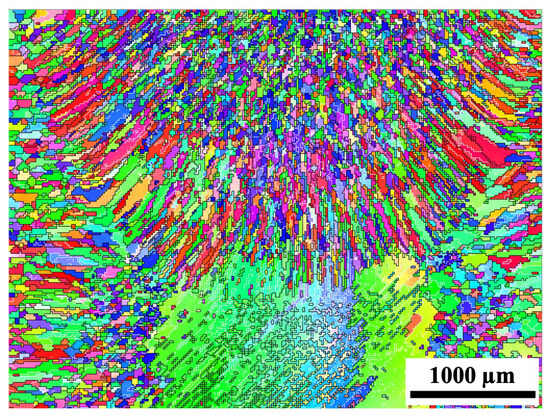
Figure 12.
EBSD analysis results at the boundary region between first-pass and second-pass.
Several studies have reported that a narrow softening zone does not significantly affect the overall mechanical properties [38,39,40] because the surrounding regions with higher hardness restrict plastic deformation, minimizing any detrimental impact. In this study, the softening zone was found to be less than 1 mm based on hardness evaluation spacing. The softening zone represents a small fraction of the total structure compared with the joint thickness of 20 mm. Based on previous research, such a localized softening effect is unlikely to compromise the overall mechanical integrity of the welded joint.
4. Conclusions
Hot-wire laser welding was conducted on aluminum alloy narrow-gap joints to assess bead formation. The key findings are as follows:
- Observations revealed three types of weld bead formation: lack of fusion and insufficient melting, suitable melting and proper bead formation, and excessive melting. Proper bead formation was achieved through a suitable combination of laser power and filler wire feeding speed.
- Reorienting the laser spot and weaving the laser spot in the welding direction enable formation of a proper bead on the final pass. Reorienting the laser spot provides sufficient penetration and bead uniformity. In addition, laser spot weaving in the welding direction avoids excessive melting at the groove edges on the surface.
- Hot-wire laser welding maintained a hardness comparable to that of the base metal, minimizing softening in the weld region.
Author Contributions
Conceptualization, J.G. and M.Y.; methodology, J.G. and S.S.; validation, K.M. and E.W.; formal analysis, J.G. and S.S.; investigation, J.G. and S.S.; resources, K.M. and M.Y.; data curation, J.G. and E.W.; writing—original draft preparation, J.G.; writing—review and editing, E.W., K.M. and M.Y.; visualization, S.S. and K.M.; supervision, E.W. and M.Y.; project administration, M.Y.; funding acquisition, E.W. and M.Y. All authors have read and agreed to the published version of the manuscript.
Funding
This research received no external funding.
Data Availability Statement
The original contributions presented in the study are included in the article; further inquiries can be directed to the corresponding author.
Conflicts of Interest
The authors declare no conflicts of interest.
References
- Aminudin, M.A.; Kamarudin, S.K.; Lim, B.H.; Majilan, E.H.; Masdar, M.S.; Shaari, N. An overview: Current progress on hydrogen fuel cell vehicles. Int. J. Hydrogen Energy 2023, 48, 4371–4388. [Google Scholar] [CrossRef]
- Muragishi, O.; Inatsu, S.; Uraguchi, R.; Yamashiro, K.; Imai, T.; Ohashi, T.; Shimogaki, T.; Yoshida, T.; Koumoto, T. Hydrogen Transportation–Development of Liquefied Hydrogen Carrier. Kawasaki Tech. Rev. 2021, 182, 35–40. [Google Scholar]
- Nakai, M.; Yasunaga, S. Aluminum Alloy Material for Storage Container for High-Pressure Hydrogen Gas. European Patent Application WO2011/115202, 22 September 2011. Available online: https://patentimages.storage.googleapis.com/4e/06/0f/6c3d900f61578e/EP2548984A1.pdf (accessed on 14 July 2025).
- Qiu, Y.; Yang, H.; Tong, L.; Wang, L. Research progress of cryogenic materials for storage and transportation of liquid hydrogen. Metals 2021, 11, 1101. [Google Scholar] [CrossRef]
- Zhang, T.; Uratani, J.; Huang, Y.; Xu, L.; Griffiths, S.; Ding, Y. Hydrogen liquefaction and storage: Recent progress and perspectives. Renew. Sustain. Energy Rev. 2023, 176, 113204. [Google Scholar] [CrossRef]
- Alireza, G.; Goroh, I.; Tomoyuki, O.; Tomoya, K. Effect of Sensitization on Hydrogen Embrittlement in a 5083 Aluminum Alloy. Mater. Trans. 2022, 63, 1425–1430. [Google Scholar] [CrossRef]
- Ardika, R.D.; Triyono, T.; Muhayat, N. A review porosity in aluminum welding. Procedia Struct. Integr. 2021, 33, 171–180. [Google Scholar] [CrossRef]
- Chen, B.-Q.; Liu, K.; Xu, S. Recent Advances in Aluminum Welding for Marine Structures. Mar. Sci. Eng. 2024, 12, 1539. [Google Scholar] [CrossRef]
- Shinozaki, K.; Yamamoto, M.; Mituhata, K.; Nagashima, T.; Kanazawa, T.; Arashin, H. Bead formation and wire temperature distribution during ultra-high-speed GTA welding using pulse-heated hot-wire. Weld. World 2011, 55, 12–18. [Google Scholar] [CrossRef]
- Peng, W.; Shan, J.; Zheng, S.; Wang, G. Control of wire transfer behaviors in hot wire laser welding. Int. J. Adv. Manuf. Technol. 2016, 83, 2091–2100. [Google Scholar] [CrossRef]
- Wei, H.; Zhang, Y.; Tan, L.; Zhong, Z. Energy efficiency evaluation of hot-wire laser welding based on process characteristic and power consumption. J. Clean. Prod. 2015, 87, 255–262. [Google Scholar] [CrossRef]
- Näsström, J.; Frostevarg, J.; Silver, T. Hot-wire laser welding of deep and wide gaps. Phys. Procedia 2015, 78, 247–254. [Google Scholar] [CrossRef]
- Lei, Z.; Cao, H.; Cui, X.; Ma, Y.; Li, L.; Zhang, Q. A novel high efficiency narrow-gap laser welding technology of 120 mm high-strength steel. Opt. Lasers Eng. 2024, 178, 108232. [Google Scholar] [CrossRef]
- Greebmalai, J.; Matsumoto, K.; Marumoto, K.; Yamamoto, M. Effect of Hardness Distribution on Strength of Narrow-Gap Hot-Wire Laser-Welded Joint for High-Tensile Strength Steel. Materials 2025, 18, 297. [Google Scholar] [CrossRef] [PubMed]
- Ning, J.; Zhang, L.J.; Yang, J.; Yin, X.Q.; Wang, X.W.; Wu, J. Characteristics of Multi-Pass Narrow-Gap Laser Welding of D406A Ultra-High Strength Steel. J. Mater. Process. Technol. 2019, 270, 168–181. [Google Scholar] [CrossRef]
- Ramakrishna, R.V.S.M.; Amrutha, P.H.; Rahman Rashid, R.A.; Palanisamy, S. Narrow gap laser welding (NGLW) of structural steels—A technological review and future research recommendations. Int. J. Adv. Manuf. Technol. 2020, 111, 2277–2300. [Google Scholar] [CrossRef]
- Yang, X.; Chen, H.; Li, M.V.; Bu, H.; Zhu, Z.; Cai, C. Porosity suppressing and grain refining of narrow-gap rotating laser-MIG hybrid welding of 5A06 aluminum alloy. J. Manuf. Process. 2021, 68, 1100–1113. [Google Scholar] [CrossRef]
- Zhao, Y.; Ma, S.; Huang, J.; Wu, Y. Narrow-Gap Laser Welding Using Filler Wire of Thick Steel Plates. Int. J. Adv. Manuf. Technol. 2017, 93, 2955–2962. [Google Scholar] [CrossRef]
- Maleki, E.; Bagherifard, S.; Rovatti, L.; Ishola, R.M.; Revuru, M.; Guagliano, M. Developing a best practice for sample preparation of additive manufactured AlSi10Mg for electron backscatter diffraction analysis. Addit. Manuf. Lett. 2023, 5, 100122. [Google Scholar] [CrossRef]
- Farzadi, A.; Serajzadeh, S.; Kokabi, A.H. Investigation of weld pool in aluminum alloys: Geometry and solidification microstructure. Int. J. Therm. Sci. 2010, 49, 809–819. [Google Scholar] [CrossRef]
- Nisar, S.; Noor, A.; Shah, A.; Siddiqui, U.; Khan, S.Z. Optimization of process parameters for laser welding of A5083 aluminium alloy. Opt. Laser Technol. 2023, 163, 109435. [Google Scholar] [CrossRef]
- Li, S.; Xu, W.; Xiao, G.; Chen, B. Weld formation in laser hot-wire welding of 7075 aluminum alloy. Metals 2018, 8, 909. [Google Scholar] [CrossRef]
- Huang, W.; Xiao, J.; Chen, S.; Jiang, X. Control of wire melting behavior during laser hot wire deposition of aluminum alloy. Opt. Laser Technol. 2022, 150, 107978. [Google Scholar] [CrossRef]
- Xu, W.H.; Lin, S.B.; Fan, C.L.; Yang, C.L. Prediction and optimization of weld bead geometry in oscillating arc narrow gap all-position GMA welding. Int. J. Adv. Manuf. Technol. 2015, 79, 183–196. [Google Scholar] [CrossRef]
- Ayoola, W.A.; Suder, W.J.; Williams, S.W. Parameters controlling weld bead profile in conduction laser welding. J. Mater. Process. Technol. 2017, 249, 522–530. [Google Scholar] [CrossRef]
- Li, S.; Mi, G.; Wang, C. A study on laser beam oscillating welding characteristics for the 5083 aluminum alloy: Morphology, microstructure and mechanical properties. J. Manuf. Process. 2020, 53, 12–20. [Google Scholar] [CrossRef]
- Geng, S.; Yang, W.; Jiang, P.; Han, C.; Ren, L. Numerical study of keyhole dynamics and porosity formation during high-power oscillating laser welding of medium-thick aluminum alloy plates. Int. J. Heat Mass Transf. 2022, 194, 123084. [Google Scholar] [CrossRef]
- Yang, T.; Liu, J.; Zhuang, Y.; Sun, K.; Chen, W. Studies on the formation mechanism of incomplete fusion defects in ultra-narrow gap laser wire filling welding. Opt. Laser Technol. 2020, 129, 106275. [Google Scholar] [CrossRef]
- Tang, Z.; Wan, L.; Yang, H.; Ren, P.; Zhu, C.; Wu, Y.; Wang, H. Stable conduction mode welding of conventional high-reflectivity metals with 2000 W blue laser. Opt. Laser Technol. 2024, 168, 109971. [Google Scholar] [CrossRef]
- Dimatteo, V.; Ascari, A.; Liverani, E.; Fortunato, A. Experimental investigation on the effect of spot diameter on continuous-wave laser welding of copper and aluminum thin sheets for battery manufacturing. Opt. Laser Technol. 2022, 145, 107495. [Google Scholar] [CrossRef]
- Faye, A.; Balcaen, Y.; Lacroix, L.; Alexis, J. Effects of welding parameters on the microstructure and mechanical properties of the AA6061 aluminium alloy joined by a Yb: YAG laser beam. J. Adv. Join. Process. 2021, 3, 100047. [Google Scholar] [CrossRef]
- Huang, S.; Lu, R.; Lou, M.; Lv, T.; Yao, J.; Li, Y. Effect of oscillation parameters on adjustable-ring mode (ARM) laser beam welding of aluminum alloys. J. Manuf. Process. 2024, 113, 307–318. [Google Scholar] [CrossRef]
- Kang, S.G.; Shin, J. The effect of laser beam intensity distribution on weld characteristics in laser welded aluminum alloy (AA5052). Opt. Laser Technol. 2021, 142, 107239. [Google Scholar] [CrossRef]
- Pang, X.; Dai, J.; Chen, S.; Zhang, M. Microstructure and mechanical properties of fiber laser welding of aluminum alloy with beam oscillation. Appl. Sci. 2019, 9, 23. [Google Scholar] [CrossRef]
- Song, M.; Geng, S.; Qiu, Y.; Xu, B.; Wang, Y.; Jiang, P.; Hu, Y.; Li, S. In-situ EBSD-DIC simulation of microstructure evolution of aluminum alloy welds. Int. J. Mech. Sci. 2024, 284, 109741. [Google Scholar] [CrossRef]
- Zhang, Z.H.; Dong, S.Y.; Wang, Y.J.; Xu, B.S.; Fang, J.X.; He, P. Study on microstructures and mechanical properties of super narrow gap joints of thick and high strength aluminum alloy plates welded by fiber laser. Int. J. Adv. Manuf. Technol. 2016, 82, 99–109. [Google Scholar] [CrossRef]
- Sánchez-Amaya, J.M.; Delgado, T.; González-Rovira, L.; Botana, F.J. Laser welding of aluminium alloys 5083 and 6082 under conduction regime. Appl. Surf. Sci. 2009, 255, 9512–9521. [Google Scholar] [CrossRef]
- Lee, Y.; Park, S.; Seon, J.; Han, H.; Lee, K.; Kang, N. Overcoming Underfill Defect with Undermatching Filler and Establishing New Acceptance Criteria for Underfill Depth in Laser Beam Welding of Ultra-High Strength Steels. Weld. World 2023, 68, 259–271. [Google Scholar] [CrossRef]
- Ran, M.M.; Sun, F.F.; Li, G.Q.; Kanvinde, A.; Wang, Y.B.; Xiao, R.Y. Experimental Study on the Behavior of Mismatched Butt Welded Joints of High Strength Steel. J. Constr. Steel Res. 2019, 153, 196–208. [Google Scholar] [CrossRef]
- Ran, M.-M.; Sun, F.F.; Li, G.Q.; Wang, Y.B. Mechanical Properties of Mismatched High Strength Steel Butt Joints with Three Softened/Hardened Strength Distribution Patterns. Thin-Walled Struct. 2020, 146, 106456. [Google Scholar] [CrossRef]


Disclaimer/Publisher’s Note: The statements, opinions and data contained in all publications are solely those of the individual author(s) and contributor(s) and not of MDPI and/or the editor(s). MDPI and/or the editor(s) disclaim responsibility for any injury to people or property resulting from any ideas, methods, instructions or products referred to in the content. |
© 2025 by the authors. Licensee MDPI, Basel, Switzerland. This article is an open access article distributed under the terms and conditions of the Creative Commons Attribution (CC BY) license (https://creativecommons.org/licenses/by/4.0/).