


Abstract
With the growing global emphasis on environmental protection, energy conservation, and emission reduction, along with rapid advances in precision machinery and manufacturing technologies, energy-efficient multi-blade centrifugal fans have become a key research area worldwide. These devices, commonly referred to as multi-blade centrifugal fans, utilize an impeller with multiple blades to transport air or gas, operating on the same fundamental principles as conventional centrifugal fans. Due to their ability to deliver high flow rates with high efficiency and stable performance, they are widely used in ventilation, air conditioning, and industrial applications. This paper provides a comprehensive review of recent advances in the research and development of multi-blade centrifugal fans. It covers key aspects of component design and optimization, including the impeller, volute, collector, and rim clearance. The review also addresses critical issues, including rotating stall, vibration, noise generation, and material selection. Furthermore, it highlights emerging perspectives, including the application of entropy production theory to elucidate flow mechanisms, strategies for performance optimization, advanced technologies for material innovation, and protective devices to enhance operational reliability and functionality. This review provides guidance for future research and development aimed at improving the efficiency and performance of multi-blade centrifugal fans across diverse applications.
1. Introduction
1.1. Background
A fan is a powered fluid machine that converts mechanical energy into increased gas pressure and flow. In China, equipment used for gas compression or transport is generally classified as fans, encompassing wind turbines, blowers, and ventilators. Fans are widely employed in applications such as ventilation, dust removal, and cooling across industries including manufacturing, mining, tunneling, cooling towers, transportation, maritime engineering, and building systems. They also play essential roles in boiler and industrial furnace ventilation, air intake systems, air-conditioning and household appliance cooling, grain drying and transport, wind tunnel airflow generation, and hovercraft propulsion [1,2].
Fans are commonly classified as centrifugal or axial-flow types according to blade configuration. Centrifugal fans, valued for their simple structure and broad applicability, typically comprise a volute casing, impeller, inlet collector, damper plate, outlet section, and supporting components such as a frame. The typical centrifugal fan structural schematic diagram is shown in Figure 1. During operation, air is drawn through the inlet by the high-speed rotating impeller, accelerated within the blade passages, and discharged through the volute, resulting in increased pressure and kinetic energy. By contrast, axial-flow fans employ a blade assembly consisting of an impeller and downstream guide vanes to drive airflow primarily along the axial direction. Centrifugal fans are distinguished by relatively high pressure rise and compact size, whereas axial-flow fans are designed to deliver higher volumetric flow rates. Owing to their pressure characteristics, centrifugal fans are widely used in applications such as range hoods.
Figure 1.
The typical centrifugal fan structural schematic diagram.
Multi-blade centrifugal fans represent a common subtype of centrifugal fans and are widely used as ventilators. They are distinguished by an impeller equipped with multiple curved blades, from which the term “multi-blade” is derived. Operating on the same fundamental principles as conventional centrifugal fans, these devices share similar structural and functional characteristics, with their multi-blade configuration specifically designed to enhance airflow control and efficiency.
In the selection of household range hoods, two key technical parameters are airflow rate and noise level. Increasing airflow generally results in higher noise, whereas reducing airflow to limit noise can diminish extraction efficiency. Airflow and noise are therefore inherently coupled, jointly determining both appliance performance and user comfort.
1.2. Purpose of This Review
As illustrated in Figure 2, research on multi-blade centrifugal fans has gained increasing prominence within the field of fluid machinery over the past 25 years. Existing studies have largely focused on performance optimization, flow mechanisms, materials, manufacturing technologies, and application domains. Despite the substantial body of published work, a comprehensive review that systematically integrates these findings remains lacking [3,4,5,6,7,8,9,10,11,12,13]. This article aims to synthesize research advances from the past decade, identify emerging research directions, and provide a clear overview of the current state of the field.
Figure 2.
Number of publications on multi-blade centrifugal fans retrieved from Web of Science (accessed on Friday, 17 April 2026).
Several review articles related to centrifugal fans have been published in recent decades, as summarized in Table 1. You et al. [3] and Qiao [4] provided general overviews on fan selection and computer-aided design but focused primarily on conventional single-blade centrifugal fans without addressing multi-blade configurations. Wu [5], Mao et al. [7], and Li and Zhu [6] reviewed aerodynamic design methods and noise reduction techniques; however, their discussions were limited to specific aspects (noise prediction or design methodology) and did not cover integrated multi-objective optimization or advanced materials. Sun et al. [8], Du et al. [12], and Liu and Yang [10] concentrated on agricultural applications, particularly cleaning fans for combine harvesters and range hoods, with limited attention to industrial or household ventilation scenarios. Shu et al. [9] focused exclusively on cross-flow fans for air conditioning, which differ fundamentally in structure and operating principles from multi-blade centrifugal fans. Jin and Wang [11] reviewed duct optimization for cabinet air conditioners, while Wang [13] summarized the development of small centrifugal fans in China, primarily from a manufacturing rather than a research perspective.
Table 1.
Comparison of existing review articles on centrifugal fans.
As shown in Table 1, none of the existing reviews provides a systematic and comprehensive synthesis that simultaneously covers impeller design, volute optimization, collector and rim clearance analysis, rotating stall, vibration/noise, and material innovations for multi-blade centrifugal fans. Furthermore, the integration of emerging intelligent optimization algorithms (e.g., machine learning, surrogate modeling) and entropy production theory—key advances in the past decade—has not been addressed in prior reviews.
The structure of this paper is outlined in Figure 3. It begins with an overview of the origins and application domains of multi-blade centrifugal fans, followed by a review of their main classifications and operating principles. The paper then examines recent advances in seven key research areas: impeller design optimization, volute optimization, collector optimization, rim clearance optimization, rotating stall behavior, vibration and noise characteristics, and component materials. Finally, it summarizes the current state of development, identifies key challenges for future research, and discusses prospects for further advancement. Overall, the findings indicate that multi-blade centrifugal fans are mature mechanical systems with continuously improving performance and declining manufacturing costs, supporting a favorable outlook for their continued development.
Figure 3.
Outline of this article.
2. Structure and Performance Characteristics of Multi-Blade Centrifugal Fans
2.1. Main Structure and Operating Principles of Multi-Blade Centrifugal Fans
2.1.1. Main Structure of Multi-Blade Centrifugal Fans
Multi-blade centrifugal fans generally consist of an impeller, a volute, a collector, a motor, and transmission components such as shafts, pulleys, bearings, and V-belts. The impeller comprises a wheel disc, blades (typically 32–64 in number), front and rear covers, and a shaft disc. The casing includes a volute, annular wall, support legs, and flanges. Blades may be forward- or backward-inclined to accommodate a wide range of airflow and pressure requirements. Volutes can also be equipped with silencers, providing significant advantages in noise reduction. The motor is typically coupled directly to the fan via the motor shaft. Multi-blade centrifugal fans can be configured as right- or left-hand rotation types; however, the impeller must rotate along the direction of the volute spiral. Viewed from the motor side, clockwise rotation defines a right-hand fan, while counterclockwise rotation defines a left-hand fan.
2.1.2. Working Principle of Multi-Blade Centrifugal Fans
Based on the principle of converting kinetic energy into potential energy, a high-speed rotating impeller accelerates the gas, which is subsequently decelerated and redirected, transforming kinetic energy into pressure to support functions such as ventilation or dust removal. The primary pressure increase occurs within the impeller and the volute expansion section [2]. In a single-stage centrifugal fan, gas enters the impeller axially, is redirected radially through the impeller, and then passes into the diffuser, where flow deceleration further converts kinetic energy into pressure. In multi-stage centrifugal fans, return-flow devices guide the airflow to successive impellers, producing higher overall pressure.
2.2. Performance Characteristics of Multi-Blade Centrifugal Fans
A multi-blade centrifugal fan primarily operates as a constant-pressure, variable-flow device. Ideally, its pressure–flow characteristic at a given rotational speed would be linear; however, internal losses and inefficiencies cause the actual curve to deviate from this ideal, exhibiting noticeable curvature [14,15].
The operating principle of a multi-blade centrifugal fan is analogous to that of a turbine compressor, though with lower gas flow rates and smaller pressure variations. In such systems, the gas is typically treated as incompressible, making changes in specific volume negligible. Fan performance is strongly influenced by key structural parameters, including the impeller, volute, and collector. Additional factors—such as rim clearance, vibration, noise, component materials, and installation position—also critically affect overall performance [16].
3. Research Status of Multi-Blade Centrifugal Fans
Multi-blade centrifugal fans are widely used in various industrial sectors because of their compact structure, stable operation, favorable pressure-generating capability, and relatively favorable energy-efficiency characteristics. These features have also made them an active subject of research in fluid machinery. Over the past decades, scholars worldwide have investigated these fans extensively, emphasizing seven key areas: impeller design optimization, volute optimization, collector optimization, rim clearance optimization, rotating stall behavior, vibration and noise effects, and component materials. Synthesizing the research in these areas is essential for advancing multi-blade centrifugal fan technology and is expected to provide valuable guidance for future design and application.
3.1. Research on Impeller Structure and Aerodynamic Performance
The impeller is a key component of multi-blade centrifugal fans, and its structural design is critical for optimizing performance. A well-designed impeller improves operational efficiency and minimizes flow losses between blades. Multi-blade centrifugal fans typically employ arc-shaped straight blades, with the impeller geometry defined by parameters such as the blade inlet and outlet angles, the ratio of inner to outer diameters, the number of blades, and blade width [17].
Samian et al. [18] investigated the effect of blade width on fan performance, reporting that impellers with wider blades accommodate a broader range of applications, while narrower blades achieve higher efficiency. They also found that fan pressure reaches a maximum when the ratio of blade width to outer diameter is 0.38. Zhang et al. [19] experimentally studied the flat straight-blade regulating gate and optimized its design by increasing the chord length at the center of the flow channel. Wei [20] conducted a comprehensive study on impeller structural parameters using a Latin square design. Their results indicated that the blade outlet angle, number of blades, wheel diameter ratio, and blade inlet angle have the most significant influence on the total pressure of a multi-blade centrifugal fan. Increasing the impeller outer diameter markedly raises total pressure but also leads to higher specific noise levels [21]. While widening the impeller can reduce specific noise, it simultaneously decreases total pressure. Adding more blades can mitigate flow separation within the impeller, enhancing both pressure and noise performance; however, an excessive blade count may cause inlet blockage, increase the outlet angle, and induce boundary-layer separation. Furthermore, more blades create additional impeller channels, increasing aerodynamic friction losses and negatively affecting total pressure and efficiency. Overall, fan performance is strongly influenced by blade width, blade number, and impeller diameter.
Huang et al. [22] performed orthogonal design experiments to evaluate the effects of impeller structural parameters on air-conditioner performance. Their results indicated that the relative influence of the investigated parameters on fan performance, in descending order, was blade outlet angle, diameter ratio, blade inlet angle, and number of blades, with the blade outlet angle showing the greatest relative influence among the investigated parameters. Kim et al. [23] investigated the effects of partitioning a multi-blade centrifugal fan impeller into two sections using an added ring. Their study showed that fan efficiency is affected by the ring’s installation position but not by its angle. Moreover, the number of blades does not influence the point of maximum efficiency. Liu et al. [24] studied the influence of the blade outlet angle on range hood performance. Their results showed that pressure and flow gains reach saturation at a 170° outlet angle, beyond which noise increases progressively. Considering airflow, efficiency, and noise, they identified 160° as the optimal blade outlet angle for maximizing overall performance. Zhang et al. [25] applied a BP neural network combined with an orthogonal algorithm to analyze the effects of impeller parameters on multi-blade fan performance. By varying the outlet angle, impeller outlet width, and blade number, they optimized fan performance, significantly increasing total pressure, expanding the high-efficiency range, and reducing noise.
Based on advances in blade design, Wang [26] improved multi-blade centrifugal fan impellers by applying velocity distribution control and minimum boundary-layer loss theory, reducing flow separation on the suction surface and enhancing fan efficiency. Shen [27,28] focused on controlling boundary-layer growth, proposing a model for average blade-channel velocity and suction-surface velocity distribution that substantially improved fan performance. Building on this work, Guo and Zhu [29] conducted experiments considering blade curvature and impeller rotation, finding that high load on the blade trailing edge minimizes impeller loss, whereas high load on the leading edge maximizes it; arc-blade impeller losses fall between these extremes. Cheng [30] developed a velocity distribution model for forward-curved centrifugal fan impellers, addressing the radial inflection in airflow caused by the trend of decreasing and then increasing blade velocity. Li et al. [31] conducted experiments and numerical simulations, showing that for impellers with identical main parameters, constant-deceleration blades exhibited a more uniform velocity distribution, no flow separation, gentler pressure gradients, and reduced flow losses within the blade channel. The jet–wake phenomenon at the impeller outlet was minimal, the velocity distribution was even, and energy loss during outflow was lower. The total pressure efficiency of constant-deceleration blades was approximately 3.1% higher than that of single-arc blades. These results indicate that the continuous deceleration blade profile outperforms the single-arc profile under equivalent impeller parameters. Wang [32] reported that for a double-arc blade profile, increasing the central angle near the blade outlet improves both airflow and pressure. Conversely, when the central angle is less than 60°, the performance of the double-arc blade may be inferior to that of a single-arc blade, limiting its advantages.
A stable blade-channel flow field is essential for minimizing vibration and noise, improving energy conversion efficiency, extending service life, and ensuring equipment safety [33,34,35]. Conversely, an unstable flow field can cause surge and intermittent vibration in multi-blade fans, making flow stability a critical metric in impeller design. Zuo and Xu [36] and Zuo et al. [37] emphasized that blade-channel structural parameters strongly influence flow stability and proposed enhancing stability by reducing the relative area of suction-surface separation in double-arc blades. Strategies to improve stability include increasing blade count, adjusting the blade outlet angle, optimizing the channel aspect ratio, and modifying the area contraction coefficient and eigenvalue of the flow field. Additionally, Li et al. [38], and Li and Liu [39] implemented bionic variable-thickness blades to reduce operational noise and friction losses in multi-blade centrifugal fans.
Lü et al. [40] performed performance and flow-field tests on multi-blade fans, revealing substantial variation in pulsation intensity within the blade wake region. They showed that optimizing the blade profile and adjusting the relationship between flow rate and blade inlet angle can effectively reduce wake size within a specific range. Furthermore, pressure differences generated by blade loading induce symmetrically distributed secondary flows in the volute cross-section, with vortex structures at the volute outlet varying according to flow rate. Kim and Seo [41] used numerical simulations to optimize forward multi-blade centrifugal fan blades, focusing on parameters such as impeller width, cutting radius, and blade position. Hsien and Huang [42] applied the fuzzy Taguchi method, considering installation angle, impeller diameter, and inlet and outlet dimensions as optimization factors. Using orthogonal array design and CFD simulations, they improved flow rate, static pressure, and noise, resulting in an optimized fan that outperformed the original prototype. Ye et al. [43] examined the effects of beveled blades on the aerodynamic performance and flow characteristics of centrifugal fans. By incorporating beveled blade designs, they modified the fan’s inlet structure to correct deviations in incoming flow, analyzing the effects of bevel movement in both radial and axial directions. The results showed that the modified inlet duct reduced friction and inlet resistance, yielding more uniform airflow and decreasing impact, vortex, and resistance losses.
In recent years, both domestic and international research have increasingly focused on the comprehensive evaluation of multiple design parameters across various performance objectives. To address the complex interactions among these parameters and identify optimal solutions, researchers have employed advanced optimization algorithms, experimental design methods, and surrogate modeling approaches [44,45,46,47,48,49,50,51].
Yang et al. [52] conducted aerodynamic experiments combining an enhanced non-dominated sorting genetic algorithm (NSGA-II) with three-dimensional Reynolds-averaged Navier–Stokes simulations (Figure 4) to perform multi-objective optimization of double-arc fan blades. They developed and optimized a double-arc blade profile to improve the efficiency and pressure of a squirrel-cage fan (Figure 5). Their results show that the optimized double-arc profile increases impeller pressure under specific operating conditions without reducing efficiency in numerical simulations. Compared with a single-arc profile, the double-arc blade achieves higher pressure but slightly lower efficiency. Zhou et al. [53] applied a modified Hicks–Henne function, designed for multi-arc and complex-curved blades, to optimize multi-blade centrifugal fan impellers. The optimization employed a Latin hypercube experimental design, refined using the AE criterion, and a Kriging surrogate model. They determined the Pareto-optimal solutions of the surrogate model using total pressure efficiency and flow rate as objectives. Numerical simulations analyzed the fan’s internal flow field before and after optimization, with CFD results validated experimentally. The optimized fan exhibited enhanced flow rate and total pressure efficiency at maximum efficiency points, substantially reducing energy consumption in building ventilation. To enhance aerodynamic performance and reduce noise in multi-blade centrifugal fans for air conditioning, Xu et al. [54] introduced a bionic groove structure at the blade tip, inspired by the drag-reduction features of mantis shrimp. The study showed that although the groove parameters had little effect on overall aerodynamic performance, the triangular bionic groove effectively suppressed vortex shedding at the trailing edge. This design produced a more uniform velocity distribution at the impeller tip, reduced tip- and shedding-vortex intensity, and mitigated flow separation within the blade channel, ultimately contributing to noise reduction.
Figure 4.
Aerodynamic performance test platform [52]: (a) Schematic diagram of the experimental system: 1—the range hood under test, 2—the cross straightener, 3—the diffuser, 4—the unit straightener, 5—the pressure measuring port, 6—the throttling device; (b) Photographs of the experimental facilities.
Figure 5.
Schematic diagram of the squirrel cage fan structure of the experimental range hood [52]: 1—air outlet collector; 2—volute tongue; 3—volute; 4—casing; 5—impeller; 6—motor; 7—air inlet collector; 8—filter.
Wada et al. [55] extended the blade-clocking concept, originally developed for compressors and pumps, to multi-blade centrifugal fan design. By adjusting the circumferential phase angle between the blades and the volute tongue, the authors demonstrated that blade clocking can effectively enhance outlet flow velocity and improve pressure distribution uniformity. Based on this concept, an innovative multi-blade fan configuration was developed, with the detailed design procedure and optimization framework illustrated in the flowchart (Figure 6). Three blade-clocking configurations with angles of 0°, 5.5°, and 10.5° were investigated (Figure 7), and the blade spacing and rotational speed were further optimized through CFD simulations coupled with response surface methodology. The results revealed that the blade-clocking angle was the dominant parameter governing outlet flow characteristics, with the 10.5° configuration achieving a total flow rate of 3.46 m3/s and the most uniform outlet velocity distribution (Figure 8). Experimental validation on a test bench further confirmed its superior flow uniformity, where the coefficient of variation (CV) of the three outlet flow rates remained below 16%, compared with 47.22% for the conventional four-blade fan under identical operating conditions. These findings highlight the effectiveness of blade-clocking strategies in mitigating circumferential flow non-uniformity and improving the aerodynamic performance of multi-blade centrifugal fans.
Figure 6.
Flowchart showing the procedure for fan blade design and optimization [55].
Figure 7.
Fan models: (a) model 1 (blade clocking angle δ = 0°); (b) model 2 (blade clocking angle δ = 5.5°; (c) model 3 (blade clocking angle δ = 10.5°) [55].
Figure 8.
Airflow velocity distribution inside the cleaning shoe: (a) clocking angle δ = 0°; (b) clocking angle δ = 5.5°; (c) clocking angle δ = 10.5° [55].
For blade profile parameterization and optimization, Wang et al. [56] proposed a Bézier curve-based blade representation method, in which the blade profile was described using a fourth-order Bézier curve with only seven control parameters. This approach enables flexible manipulation of blade curvature along different chordwise positions while overcoming the limitations associated with conventional parameterization techniques, thereby achieving smoother blade geometries (Figure 9). The authors employed an optimal Latin hypercube design to generate representative sampling points and established surrogate models based on radial basis function neural networks (RBFNNs) to correlate geometric parameters with static pressure and static pressure efficiency. The developed models achieved high predictive accuracy, with determination coefficients (R2) of 0.98 and 0.96 and prediction errors within 1% (Figure 10). Subsequently, a multi-objective genetic algorithm was integrated with the surrogate models for aerodynamic optimization. The optimized blade configuration exhibited increased curvature at the inlet region and smoother transitions in the mid-to-trailing-edge sections, effectively suppressing trailing-edge separation vortices on the suction surface (Figure 11), reducing leading-edge incidence losses, and decreasing overall entropy generation (Figure 12). Consequently, the optimized fan achieved an increase of 12.7 Pa in static pressure and a 3.2% improvement in static pressure efficiency at the design operating point. This study demonstrates that Bézier curve-based parameterization combined with surrogate-assisted optimization provides an effective approach for blade geometry refinement in volute-free centrifugal fans.
Figure 9.
The variation range of blade profile [56].
Figure 10.
The errors between prediction and numerical values of verification samples of (a) static pressure and (b) static pressure efficiency [56].
Figure 11.
Streamline of fans [56].
Figure 12.
Entropy generation rate of fans [56].
Jin et al. [57] developed a performance prediction framework based on a variable-weight particle swarm optimization-enhanced backpropagation neural network (wPSO-BP). In this model, the particle swarm optimization algorithm was employed to optimize the initial weights and thresholds of the BP neural network, while a dynamically decreasing inertia weight strategy was introduced to enhance global exploration capability. The results indicated that the proposed wPSO-BP model exhibited significantly improved prediction accuracy compared with the conventional BP neural network for estimating total pressure, efficiency, and sound pressure level of multi-blade centrifugal fans, with the predicted results showing higher consistency with experimental data (R2 approaching unity) (Figure 13). Furthermore, the authors proposed an NSGA-III-LBWO multi-objective optimization framework, in which a Logistic chaotic mapping strategy was incorporated during population initialization to improve population diversity and convergence performance. By integrating the wPSO-BP prediction model with the NSGA-III-LBWO optimization algorithm, the prototype fan was simultaneously optimized for aerodynamic and acoustic performance. The optimized design achieved notable improvements in both flow performance and noise reduction characteristics. This work demonstrates the potential of intelligent optimization algorithms for addressing the coupled aerodynamic–acoustic design challenges of multi-blade centrifugal fans and provides a promising pathway toward data-driven, multi-objective fan optimization.
Figure 13.
Comparison between predicted and calculated values: (a) Total pressure. (b) Efficiency. (c) Sound pressure level [57].
3.2. Research on Volute Structure and Flow Characteristics
The volute is a key component of a multi-blade centrifugal fan, comprising a casing and two side plates that are either welded or assembled. Its primary function is to collect airflow from the impeller outlet, expand it, and direct it along a defined pathway. Core challenges in volute design and integration include minimizing energy consumption, controlling noise, and satisfying operational requirements.
The design of volute profiles in traditional centrifugal fans is generally based on several assumptions: uniform distribution of impeller velocity vectors around the circumference, ideal continuous flow within the volute, and conservation of airflow momentum. This theoretical framework typically produces a logarithmic-spiral volute profile [58,59,60]. In practice, several primary design methods are employed to facilitate modeling and manufacturing, including the equal-annular-volume method, Archimedean-spiral equation method, average-velocity method, structural-square method, and unequal-distance-square method [61,62].
Lv et al. [63] refined the volute profile by incorporating a flow-correction coefficient into the logarithmic-spiral formula, better aligning it with actual operating conditions. Zheng et al. [64] optimized the volute by increasing the radius of the volute tongue and modifying the profile, achieving a more uniform velocity and pressure distribution, enhancing the flow and pressure fields, reducing noise, and increasing airflow. Additionally, several studies [65,66,67] explored the effects of offsetting the impeller shaft from the volute center, showing that this adjustment can improve overall fan performance under specific conditions. Lei et al. [68] used Ansys Fluent to perform numerical simulations of various volute structural modifications, including the volute tongue and volute width. Their study evaluated the effects of these changes on overall fan performance and noise characteristics. Morinushi [69] found that centrifugal fan performance is optimized when the volute outer diameter is 12.5 times the radius of the small arc of the volute tongue. Kang et al. [70] observed that variations in the cross-sectional shape of the volute tongue throat and the size of the volute tongue stagnation point can produce uneven velocity distribution at the impeller outlet. They identified a volute tongue angle of 62° as optimal for fan performance. Kim and Seo [71] used CFD to investigate the effects of impeller width, volute tongue radius, volute tongue position, and volute outlet diffusion angle on fan performance. Their results showed that the optimized fan achieved higher efficiency than the prototype. They found that efficiency was not directly related to the size of the inactive area at the impeller outlet but was strongly influenced by the volute tongue position and diffusion angle, with a notable correlation to impeller width.
Many studies have revised the assumption of uniform flow to account for the strong interference of the non-axisymmetric volute with impeller performance. Kurokawa [72] addressed this issue by using the experimentally measured impeller outlet velocity as the initial condition for volute design. Qi et al. [73,74] further investigated variable inlet flow conditions in a two-dimensional inverse design of volute profiles. By incorporating entropy-based methods and gas viscosity effects to calculate the radial velocity gradient, they iteratively adjusted the volute expansion angle. A profile with an expansion angle that first increases and then decreases exhibited improved aerodynamic performance compared with conventional designs. Song and Xie et al. [75] analyzed multiple volute design approaches, comparing their respective advantages and limitations while examining pressure and velocity distributions within the volute. They established a theoretical basis for volute optimization and introduced a variable helix angle concept, emphasizing the importance of accounting for volute radius and curvature under different operating conditions. Key flow-correction parameters for volute radius design were also identified. Pan et al. [76] proposed two volute profile design methods based on equilateral and non-equilateral reference geometries; both produced similar cross-sectional flow characteristics at low specific speeds, whereas their influence on fan performance was limited at high specific speeds. Li [77] further improved fan performance by introducing a novel volute structure incorporating a variable helix angle. Zhou [78] optimized the volute profile based on the momentum-moment distribution of the actual vortex field, resulting in reduced vortex intensity and lower fan noise. Wu and Huang [79] employed momentum interpolation to develop a pressure correction algorithm and combined it with TM grid generation techniques to numerically simulate vortex structures within the volute. Their results demonstrated that variations in the relative arrangement of the volute and impeller significantly modify vortex behavior and the internal flow field, leading to distinct vortex structures. Li et al. [80] investigated the formation mechanism of vortical structures at the volute outlet of multi-blade centrifugal fans through numerical simulations. The results revealed that, owing to the relatively large blade width and short flow passages, the airflow retains a considerable radial velocity component within the impeller channels. This persistent radial flow component promotes the development of vortical structures in the volute outlet region, where the flow field exhibits a distinct separation into outward discharge and reverse-flow regions (Figure 14). These vortices further deteriorate the flow conditions in the impeller passages adjacent to the volute side (Figure 15), leading to additional flow disturbances and aerodynamic losses. Furthermore, streamline distributions within the volute cross-sections (Figure 16) demonstrated pronounced secondary flows and recirculation phenomena. The elevated static pressure in the reverse-flow regions was identified as a primary driving factor for vortex generation. Meanwhile, the induced vortical motion promotes the return of flow from the volute region into the impeller passages, while the secondary flow near the impeller gradually migrates from the volute center towards both side regions. These findings provide important insights into the interaction between impeller–volute coupling effects and internal flow instability in multi-blade centrifugal fans.
Figure 14.
Streamline diagram with different flow coefficient: (a) φ = 0.435; (b) φ = 0.609; (c) φ = 1.175 [80].
Figure 15.
Absolute velocity distribution on-line B-Outlet-Z: (a) B-Outlet-Z25; (b) B-Outlet-Z50; (c) B-Outlet-Z75; (d) B-Outlet-(0–90°) [80].
Figure 16.
Streamline of Section S in multi-blade fan: (a) section S in fan; (b) streamline on section S [80].
Wang et al. [81] performed numerical simulations of a centrifugal fan with a trapezoidal volute using a time-marching Jameson scheme to solve the time-averaged Navier–Stokes equations in conjunction with the Baldwin–Lomax turbulence model. Their results showed that each radial section of the trapezoidal volute contains a pair of counter-rotating vortices with alternating strengths. The vortex strength increased with flow rate, and the associated onset losses contributed to higher total pressure losses. Consequently, the influence of these vortices on fan performance varied with operating condition. Gong et al. [82] employed a five-hole probe to measure the three-dimensional flow field within the volute of a centrifugal fan featuring a wide rectangular cross-section at three flow rates. The measurements revealed substantial deviations from the equal-annular-flow assumption commonly adopted in volute design. Based on these findings, the authors proposed revising the conventional one-dimensional volute design methodology to improve fan performance. Dilin P. et al. [61] experimentally characterized the pressure and velocity distributions over a wide operating range for two centrifugal fan volute configurations: a full volute tongue and a reduced volute tongue. They further simulated and predicted the internal flow fields of both designs, with particular emphasis on flow separation phenomena occurring near the respective volute tongues. He and Sato [83], Kind and Tobin [84], and Panovsky and Kielb [85] measured the impeller inlet and outlet dimensions, as well as the velocity and pressure distributions within the volute. Their analysis revealed pronounced spatial variations in airflow velocity at both the impeller inlet and outlet. In particular, the flow exhibited strong non-uniformity in the radial and axial directions at the impeller outlet, with the maximum velocity occurring in the volute outlet region. Fang et al. [86] treated the angular position and depth of volute cuts as independent variables and optimized multiple volute profile configurations through numerical simulations. Their results showed that, for a given volute width, a large volute with cuts significantly improved the internal flow field within the blade passage compared with the uncut configuration and also outperformed a small volute without cuts. Xiao et al. [87] integrated genetic algorithms with B-spline curve parameterization to automatically reconstruct and optimize the volute profile under prescribed geometric constraints.
Liu et al. [88] developed a three-dimensional wavy leading-edge airfoil with varying wave direction angles, inspired by the wavy leading-edge structure of humpback whale fins, to evaluate the adaptability of this bionic design under different angles of attack. Based on this concept, they proposed a bionic volute tongue optimization method and systematically investigated its effects on the internal flow field and noise characteristics of a multi-blade centrifugal fan. The results showed that when the wave direction angle was 45°, the wavy leading-edge structure effectively suppressed leading-edge separation vortices and wake vortex shedding, thereby contributing to noise reduction. Moreover, the bionic volute tongue with a wavy leading-edge structure was well suited to conditions with small impeller outlet flow angles. Under maximum flow-rate conditions, the fan equipped with the bionic volute tongue exhibited an approximately 5% higher static pressure recovery coefficient, a 5.16% increase in airflow rate, and a 0.6 dB reduction in noise compared with the original design. In addition, Huang et al. [89] proposed a gradient-radius volute tongue configuration to overcome the limitation of conventional volute designs with a uniform tongue radius distribution along the axial direction (Figure 17). Based on this modified geometry, the influence of different maximum tongue-radius schemes on overall acoustic performance was systematically evaluated. The results indicated that the configuration with a maximum radius of 22 mm at the disc-side achieved the most pronounced noise reduction, decreasing the overall sound level by 3.5 dB compared with the baseline fan (Figure 18). Furthermore, the study demonstrated that introducing an axially varying volute tongue radius provides an effective approach for balancing aerodynamic performance and noise suppression. However, the authors also emphasized that the volute tongue geometry should be optimized in conjunction with impeller parameters, as the aerodynamic–acoustic characteristics of multi-blade centrifugal fans are strongly influenced by the coupled interaction between the impeller and volute.
Figure 17.
The differences between “common volute tongue structure” and “gradient-radius volute tongue structure” [89].
Figure 18.
Influence of volute tongue structure with gradient-radius on fan noise [89].
Wu et al. [90] further developed a Bayesian multi-objective optimization framework assisted by a radial basis function (RBF) surrogate model, in which three critical volute geometric parameters, including tongue radius, tongue clearance, and axial clearance, were selected as design variables to simultaneously improve total pressure efficiency and reduce aerodynamic noise. Thirty samples generated using a Latin hypercube design were employed to construct the surrogate model, while CFD simulations coupled with the Ffowcs Williams–Hawkings (FW-H) acoustic analogy were adopted to obtain aerodynamic and acoustic responses. The developed RBF models exhibited excellent predictive capability, achieving leave-one-out cross-validation coefficients of determination (R2) of 0.978 for noise prediction and 0.995 for efficiency prediction. Based on the design requirements of household ventilation fans, a low-noise optimization strategy with a noise-to-efficiency weighting ratio of 70:30 was selected. The optimized configuration was subsequently validated through independent CFD simulations, achieving a sound power level of 59.19 dB and a total pressure efficiency of 0.554, corresponding to a noise reduction of 4.41 dB and an efficiency improvement of 2 percentage points compared with the original design. Moreover, the sound pressure level at the characteristic frequency of 2550 Hz was reduced by 9.9 dB (Figure 19). Flow-field analysis revealed that the optimized volute tongue clearance weakened the interaction between the high-speed impeller outlet jet and the tongue region, thereby reducing local high-velocity zones, suppressing recirculation regions, and significantly decreasing pressure fluctuation amplitudes (Figure 20). This study highlights the potential of surrogate-model-assisted optimization for achieving coordinated aerodynamic and acoustic improvements in multi-blade centrifugal fans and provides a valuable methodological framework for multi-objective optimization of other rotating fluid machinery.
Figure 19.
Noise spectra comparison of optimized model and original model [90].
Figure 20.
Velocity nephogram of original model (a) and optimized model (b) at section z = −40 mm [90].
Overall, volute design has evolved from conventional analytical methods toward CFD-based analysis and advanced optimization approaches, as summarized in Table 2.
Table 2.
Comparison of volute design and optimization approaches.
3.3. Research on Collector Structure and Inlet-Flow Characteristics
The collector of a multi-blade centrifugal fan plays a critical role in accelerating the incoming airflow and ensuring a uniform velocity distribution at the impeller inlet while minimizing pressure losses. Owing to the characteristic features of multi-blade centrifugal fans—namely, short blade lengths and large impeller diameters—these systems commonly employ equal-width impellers with relatively large axial widths. The collector is typically designed with an arcuate profile, and its overall geometry is defined by parameters such as collector length, outer diameter, and inlet arc radius. The aerodynamic performance of the entire fan system is strongly influenced by the collector’s spatial position, as well as by the size and structural configuration of its inlet and outlet.
Lin Shiyang et al. [91] focused on reducing flow losses through fan design optimization. Using the SIMPLEC algorithm in conjunction with the PHOENICS code and the standard k–ω turbulence model, they analyzed the inlet velocity field. By reshaping the tapered inlet section—specifically by decreasing the taper angle and increasing the curvature of the throat—they effectively reduced internal flow losses and improved overall fan performance. These design modifications not only suppressed boundary-layer separation but also alleviated flow disturbances near the leading edge of the front disk. Zhuang [92] experimentally demonstrated that the axial clearance between the collector and the impeller has a pronounced influence on fan performance. At high flow rates, an appropriate clearance is essential: insufficient clearance disturbs the airflow entering the impeller, whereas excessive clearance leads to performance degradation. Furthermore, a collector outlet diameter larger than the inner diameter of the impeller front disk can improve both flow rate and efficiency distribution. Gholamian et al. [93,94] reported that reducing the axial clearance to a value smaller than the impeller inner diameter weakens vortex formation near the blade front disk, thereby enhancing fan performance. Overall, these studies indicate that optimal comprehensive performance is achieved when the collector pipe diameter closely matches the impeller inner diameter. Fukutomi et al. [95] introduced the concept of “eccentric installation and non-circular design” for collectors, representing a notable advancement in collector optimization. By positioning the collector eccentrically relative to the outlet, a gap-induced circulation flow forms between the impeller and collector, enhancing the impeller’s work capacity by occupying the suction surface flow within the blade channels. This configuration reduces gas flow within the volute, increases static pressure, and improves overall fan operating pressure. Yang et al. [96] extended this eccentric design across various operating conditions to determine optimal eccentric parameters. Huang and Qin [97] proposed an elliptical collector and employed the response surface method to identify the optimal eccentric angle and eccentricity. Wen et al. [98] found that although an elliptical inlet collector enhances fan performance, it also increases noise levels. Collectively, these studies highlight that the collector’s geometry, positioning, and parameters critically influence fan performance, with the elliptical design notably improving flow conditions near the volute outlet. Wang and Ou [99] analyzed the effects of different collector convergence profiles on the inlet flow field and aerodynamic performance of multi-blade centrifugal fans. They found that a converging collector with an inner diameter larger than the outlet cross-section markedly improved impeller airflow utilization. This configuration reduced the influence of leakage flows on the main inlet airflow, thereby enhancing overall flow stability and fan performance. Hou [100] optimized the air inlet arc radius and performed numerical simulations under turbulent conditions. He found that although reducing the axial overlap or radial gap when the collector outlet diameter is smaller than the impeller inner diameter increases energy loss, it can also improve overall fan efficiency. Son et al. [101] used CFD to investigate a multi-blade fan collector and demonstrated that the collector radius substantially affects the fan flow rate, with variations of approximately 5%, whereas the gap between the collector and impeller inlet has minimal influence. Experimental validation confirmed the accuracy of these numerical predictions. Ding et al. [102] investigated the performance of industrial ventilators under two different air intake configurations. Their results showed a 6.5% increase in efficiency and a 203 Pa rise in pressure at the mixing chamber inlet. The fan achieved optimal performance at a flow ratio of 5 with a stable mass flow rate. Furthermore, extending the mixing chamber length to 100 mm led to a 2% increase in blast velocity and a 70 Pa rise in pressure.
The primary function of a fume hood is to capture kitchen oil fumes while maintaining a stable and uniform airflow at the air inlet, minimizing flow losses and preventing fume escape. Current research, both domestic and international, predominantly investigates how various internal and external structural configurations affect oil fume capture efficiency. Numerical simulations of range hoods [103,104,105,106] generally focus on different hood types and show good agreement with experimental results, demonstrating the reliability of computational approaches. Zheng and Wang [107] employed computational fluid dynamics (CFD) to simulate the three-dimensional flow field of range hoods, examining flow characteristics, predicting maximum airflow, and validating these predictions against experimental data. Their study also analyzed radial and axial flow within the hood and secondary flow outside the volute tongue in detail. Fu et al. [108] applied third-order NURBS spline curves combined with aircraft wind tunnel wall enhancement techniques and numerical simulations to optimize a large range hood, achieving a 4.2% average improvement in dust removal efficiency. Wang [109] investigated oil smoke behavior within range hoods, showing that the flow characteristics induced by the impeller-generated negative pressure are influenced by multiple factors.
Kim et al. [110] investigated the influence of inlet and outlet design on the performance of centrifugal fans used in household refrigerators. They aimed to reduce flow losses by optimizing parameters, including blade tip clearance, internal grilles, and guide vanes. Their study demonstrated that fan performance is highly sensitive to guide vane design, with installation angle, position, height, and length being key factors. Optimization of these parameters improved overall fan performance and enhanced inlet flow characteristics. Xu et al. [111] and Xu [112] proposed that the optimal strategy for balancing fan airflow and noise is to set the collector outlet diameter equal to the mean of the impeller’s inner and outer diameters. Zhao et al. [113] investigated key collector geometric parameters, including the expansion angle, contraction angle, and expansion length, and established their functional relationships with fan efficiency and sound power levels. Their results indicated that, although the collector dimensions have minimal influence on sound power, the expansion and contraction angles substantially affect the fan’s aerodynamic performance. Qu and Liu [114] developed an elliptical collector and demonstrated experimentally that, with other geometric parameters and impeller speeds held constant, appropriately enlarging the collector flow area increases the fan’s airflow. However, this increase also results in higher operating noise. The study further showed that strategic positioning of the elliptical collector can enhance airflow while mitigating the corresponding rise in noise levels.
Overall, collector design has evolved from conventional CFD-based parametric analysis toward geometric optimization and response-surface-based approaches, with increasing attention to the trade-offs between aerodynamic performance and noise, as summarized in Table 3.
Table 3.
Comparison of collector design and optimization approaches.
3.4. Research on Rim Clearance, Leakage Flow, and Vortex Dynamics
During operation, fans are subject to complex flow phenomena, including severe flow separation and leakage [115]. In multi-blade centrifugal fans, gaps between the impeller rim and the volute can induce flow separation and leakage, disrupting the internal flow field. At low flow rates, these separation vortices may propagate through the impeller channels at reduced velocity, opposing the impeller’s motion and potentially triggering rotating stall [116].
Since the 1970s, researchers worldwide have investigated gap flow and vortex dynamics through theoretical and numerical studies. Following Yamamoto’s [117] introduction of a simplified model for gap leakage vortices, academic interest in understanding these complex mechanisms has intensified. Early work primarily focused on theoretical analyses and experimental investigations [118,119,120,121,122,123,124,125,126,127,128], addressing various aspects of gap flow. Today, the influence of rim clearance on fluid machinery is mainly studied in compressors and pumps. In centrifugal compressors, tip clearance leakage is a critical factor affecting impeller pressure ratio and overall efficiency [129,130].
Liao et al. [131] performed numerical simulations of three-dimensional turbulent flow in the rim gap of an axial-flow propeller turbine using the Reynolds-averaged Navier–Stokes equations, the Reynolds stress differential model, and unstructured grid techniques. The study analyzed leakage flow velocity distributions within the rim gap, along the blade surface, and under varying operating conditions, with experimental results validating the simulations. Liu et al. [132] applied the semi-implicit method for pressure-linked equations (SIMPLEC) combined with covariant physical separation to simulate centrifugal compressor flow with tip clearance leakage. Their results showed that tip clearance leakage not only disrupts the impeller flow structure and performance but also adversely affects the bladeless diffuser and overall stage performance. Li and Wang [133] employed the low-Reynolds-number k–ε turbulence model and the artificial compressibility method to solve the Navier–Stokes equations, simulating axial flow in blade cascades with tip clearance.
Advances in computational technology have greatly enhanced numerical simulation, enabling more accurate modeling of natural and engineered systems [134,135,136,137]. These developments in CFD and computer-based methods have deepened research across fluid mechanics and related fields, improving understanding of complex flow phenomena [138,139,140,141,142,143]. Miorini et al. [144] used high-resolution two-dimensional particle imaging in jet pumps to identify unsteady vortex filaments forming leakage vortex structures. Wu [145,146] combined PIV and CFD to investigate leakage vortex fields in jet propellers, highlighting their pronounced three-dimensional characteristics. Sai [147] analyzed centrifugal compressor flow fields near stall, showing that gap leakage vortices intensified and migrated upstream as flow rates decreased. Li [148,149] employed large eddy simulations to study unstable flow in axial-flow pumps, demonstrating that instability increased with clearance size and that pressure fluctuations followed a proportional relationship. Liang [150] simulated blade tip clearance in axial-flow pumps using CFD, comparing energy characteristics across clearances and validating results experimentally. Goto [151] performed three-dimensional calculations of tip leakage flows, finding increased backflow with larger blade tip clearances. Mattern [152] tested and optimized blade tip clearance in centrifugal compressors, suggesting efficiency and pressure ratio improvements through clearance adjustments. Seshadri et al. [153] highlighted the role of leakage vortices in compressor stall. Zhao et al. [154] analyzed blade edge flow in compressors using steady-state and transient methods, observing greater instability on the working surface. Li et al. [155] investigated edge flow in mixed-flow impellers near stall, linking leakage flows to rotational stall. Zhu [156] examined gap leakage effects on impeller performance, revealing radial variations in leakage flow distribution. Liao [157] studied rim gap flows in axial-flow turbines, identifying cavitation effects associated with wake conditions. Zhang et al. [158] applied the Reynolds stress model in numerical simulations, emphasizing the importance of optimized turbine design. Xu et al. [159] investigated the effects of upstream wake vortices on the unsteady behavior of downstream tip leakage flow in a high-load counter-rotating compressor using numerical simulations. As shown in Figure 21 and Figure 22, their results demonstrate that upstream vortices substantially influence the flow dynamics and overall performance of the compressor.
Figure 21.
Screen for single blade channel [159].
Figure 22.
Comparison of TLF with and without trailing vortex under N − S conditions [159].
In-depth analysis leads to the following conclusions for counter-rotating compressors (Figure 23). The intensity of the tip leakage vortex (TLV) exceeds that of the upstream wake vortex. Under near-stall (NS) conditions, the TLV overflows from the leading edge (LE) of the adjacent blade, whereas the wake vortex bypasses the interface formed by the TLV and mainstream, flowing directly beneath the tip. This interaction divides and rapidly attenuates the TLV. During NS conditions, the primary frequency (TE) of static pressure fluctuations near the trailing edge approximates one relative blade passing frequency (RBPF). When the TLV breakdown is pronounced, it contributes to the primary frequency near the LE. Consequently, under NS conditions, two dominant frequencies appear in the tip region of the downstream supersonic rotor: one near the LE and the other near the TE. The TLV reduces the compressor’s operating frequency, hindering stable operation. With small tip clearance, the upstream wake vortex increases the momentum ratio when static pressure fluctuations induced by the TLV at the downstream rotor LE occur. This effect exceeds the threshold for TLV self-excited fluctuations, suggesting that the wake vortex helps suppress TLV self-excitation.
Figure 23.
Performance of counter-rotating compressors under different operating conditions: (a) Isentropic efficiency; (b) Total pressure ratio [159].
Overall, research on rim clearance and leakage flow has evolved from theoretical and experimental investigations toward CFD-based and high-fidelity numerical analyses, with increasing attention to vortex dynamics and flow instability, as summarized in Table 4.
Table 4.
Comparison of research approaches for rim clearance and leakage flow.
3.5. Study on Rotating Stall Characteristics
Rotational stall is an unstable flow phenomenon that frequently occurs in turbomachinery at low flow rates. It reduces overall machine performance, narrows the efficient operating range, and compromises stability and reliability; in severe cases, it can even cause catastrophic failure. Predicting stall onset and avoiding operation under such conditions are critical in turbomachinery design and operation. To elucidate the mechanisms of flow instability at low flow rates and to develop targeted control strategies, researchers worldwide have extensively investigated these phenomena, yielding significant insights and advancements [160,161].
Since the 20th century, rotating stall has attracted considerable attention, with extensive research conducted worldwide. In 1955, Emmons et al. [162] first proposed a mechanism for compressor rotating stall. In the 1980s, Moore et al. [163] applied small perturbation and limit cycle theories to investigate compressor stall under various boundary conditions, collaborating with Greitzer [164] to develop the unified Moore–Greitzer model. As theoretical understanding advanced, experimental and numerical simulation methods became widely used to study this phenomenon. Cumpsty [165] demonstrated experimentally that the frequency of rotating stall typically ranges from 0.2 to 0.5 times the rotor rotation frequency, enabling detection of stall by monitoring impeller outlet frequency.
In numerical simulations, Choi et al. [166] employed a three-dimensional compressible Reynolds-averaged Navier–Stokes (RANS) solver to investigate rotating stall. Their results showed that as fan speed increased, stall cluster size grew, while the number of clusters decreased. Similarly, Yoon et al. [167] examined flow stability in centrifugal compressors and predicted the onset location, quantity, and velocity of stall clusters. Their analysis revealed a positive correlation between cluster velocity and flow rate, whereas the number of stall clusters decreased with increasing flow rate.
Semlitsch et al. [168] conducted a comprehensive numerical simulation of a centrifugal compressor to investigate its internal flow dynamics under surge conditions. Their analysis revealed low-frequency pulsations at both the inlet and outlet under minimum flow conditions. Bousquet et al. [169] examined flow behavior within the impeller and diffuser during flow reduction (Figure 24 and Figure 25), elucidating the mechanisms of rotational stall. Their results showed that flow reduction induces boundary layer separation on the suction surface of the diffuser blade leading edge.
Figure 24.
Illustration of the flow mechanism in the blade tip region (left) and the time-averaged meridional velocity reduction profile of section B at the OP3 operating point (right) [169].
Figure 25.
Contours of instantaneous static pressure at the front cover and impeller inlet [169].
Li and Wu [170,171,172], among others, conducted single-channel numerical simulations of the transonic compressor, validating their results against experimental data. Their findings elucidated the origins of unsteady flow fluctuations and the formation of secondary vortices at the blade tip. Wang et al. [173,174] used computational fluid dynamics (CFD) to analyze centrifugal compressor performance near stall and proposed a simulation approach to increase outlet pressure and approach the stall point, which was subsequently validated experimentally. Zhang et al. [116,175] investigated the effects of diffuser inlet angle, wave number, and radius ratio on rotating stall, demonstrating that an increased diffuser radius ratio intensifies flow instability and accelerates stall onset. Li et al. [176] performed numerical simulations of a subsonic axial-flow compressor under near-stall conditions, identifying criteria for spike-wave formation. Xu et al. [177] introduced the SVRM model, which accurately predicts rotating stall in centrifugal fans. Zhang et al. [178] analyzed unsteady flow in centrifugal fans, showing that internal noise primarily arises from unstable gas flow at the impeller outlet impacting the volute wall.
In experimental studies, Jenny et al. [179] investigated the interaction between unsteady flow structures and rotating stall at the impeller. Their results showed that the relationship between these phenomena varies with operating conditions. Ahmed et al. [180] observed that reflow occurs along the diffuser wall and that the reflow region expands during rotating stall events. Guo et al. [181] employed Particle Image Velocimetry (PIV) to examine rotating stall in centrifugal compressors, finding that variations in flow rate have minimal impact on stall frequency. Hou et al. and Liu et al. [182,183] investigated the mechanisms of rotational stall in centrifugal fans experimentally. Their analysis revealed insights into stall frequency, pulsation characteristics, and variations in performance parameters at the suction surface. Under near-stall conditions, approximately two-thirds of the fan rotation frequency exhibited disturbance components. Entering the weak stall zone led to a significant increase in frequency energy associated with the stall group, emphasizing the importance of monitoring this stage. Zhang and Wang et al. [184,185,186] employed an air cavity model to simulate the transformation of flow pulsation signals during stall and analyzed the unstable flow field using entropy production. They further demonstrated that active nozzle blowing [187] can delay stall onset and improve the fan’s safety margin. Xiao [188] numerically examined the evolution of the jet-wake structure in double-suction centrifugal fan blades under low-flow conditions, finding that the low-pressure region at the impeller outlet, intensified by rotating stall, grows as flow rate decreases, potentially leading to surge.
3.6. Research on Fan Vibration and Noise Characteristics and Reduction
Multi-blade centrifugal fans are widely employed in both residential and industrial ventilation. Beyond aerodynamic performance, their overall effectiveness is also assessed by operational vibration and noise levels.
During operation, fans generate significant noise, primarily comprising mechanical and aerodynamic components. Mechanical noise originates from vibrations within structural elements, including electromagnetic noise from the motor and casing vibrations. Aerodynamic noise arises from turbulent airflow and gas–solid interactions during air transport and can be further classified into discrete and vortex noise. Discrete noise, or rotational noise, results from periodic pressure fluctuations between the airflow and the volute as the impeller rotates, producing substantial sound pressure at the blade rotation frequency. Vortex noise, or broadband noise, lacks a distinct frequency pattern and spans a wide frequency range. It is caused by interactions between disturbed airflow and static surfaces, leading to boundary layer separation on the blades, trailing-edge jet-wake formation, airflow separation at the volute outlet, and disturbances in the volute flow [189].
Extensive research, both domestic and international, has sought to address aerodynamic noise and enhance fan performance. However, the complexity of the underlying theories and the intricate geometries involved—such as volute profiles and blade trailing edges—poses significant challenges for numerical simulations, often preventing a comprehensive theoretical resolution of noise issues. Consequently, identifying fundamental solutions to aerodynamic noise remains a major challenge. This has made the optimization of fan structures to improve internal flow and reduce operational noise a central focus of research worldwide.
Ma et al. [190] investigated the influence of volute tongue structural parameters on centrifugal fan vibration and noise using a dedicated experimental platform. By orthogonally varying the parameters of two volute tongue designs, they demonstrated that adjusting the volute tongue layout significantly reduced vibration, particularly near the blade frequency. The inclined volute tongue effectively mitigated blade-frequency vibrations, with minimal differences observed between inclination angles. The volute tongue area, identified as the fan’s region of maximum vibration, exhibited the largest amplitude fluctuations in response to structural changes. Furthermore, increasing the installation spacing on the volute separation bracket proved more effective for vibration suppression than modifying the tongue inclination angle. Dong and Dou [191] developed a bionic volute tongue inspired by the leading edge of an owl’s wing. Using reverse modeling, they extracted the cross-sectional profile of the owl’s long-eared wing, known for its aerodynamic efficiency, and incorporated it into the volute tongue design. Numerical simulations compared the aerodynamic and noise characteristics of the prototype fan with those of the bionic configuration. Results showed that the bionic fan achieved a higher volumetric flow rate, a 1.6 dB reduction in noise, and a 3.8% increase in efficiency. The leading-edge design of the bionic structure effectively mitigated aerodynamic resistance, enhancing overall fan performance. Within the volute tongue region, the adverse pressure gradient was substantially reduced, modifying vortex structures, distribution, and intensity.
Aerodynamic noise can be categorized into three types: monopole, dipole, and quadrupole sources. These noises originate from unsteady processes in the gas or from interactions between the gas and solid components. In centrifugal fans, monopole and quadrupole noises are generally negligible under normal operating conditions. The primary concern is dipole noise, which encompasses eddy-current noise and rotational noise, depending on their respective generation mechanisms.
Currently, researchers worldwide have investigated noise reduction in centrifugal fans using three primary approaches [192,193,194]: (1) analyzing the influence of geometric parameters—such as volute tongue clearance, curvature radius, and height—on the volute tongue shape; (2) optimizing the impeller’s internal flow field by adjusting blade geometry and refining the blade path both internally and externally; and (3) employing sound-absorbing structures or materials to attenuate noise.
Li et al. [195] investigated aerodynamic pulsations arising from rotational flow separation under low-flow conditions in centrifugal fans and proposed solutions for fan–duct structural vibrations, based on operational experience in a power plant boiler air supply system. Gao et al. [196] identified sources of abnormal fan vibrations, including defects in bearings and bearing seats that caused dynamic imbalance, and achieved compliance with vibration standards following targeted adjustments. Xie [197] analyzed the structural and operational characteristics of large centrifugal-induced draft fans, identifying bearing vibrations and issues with sliding components and bearing seat anchor bolts. Li [198] employed hammer and sinusoidal excitation methods to evaluate the natural frequency of fan impellers and adjusted the impeller’s natural frequency by welding a ring to mitigate resonance with excitation frequencies.
Wang et al. [199] conducted preliminary calculations and experimental validations of the natural frequencies of a centrifugal fan volute, analyzing its forced vibration and noise under various operating conditions. Their study provides valuable insights for noise reduction in small forward-curved centrifugal fans. Cai et al. [200,201] performed numerical simulations of the volute’s response to unsteady aerodynamic forces in a centrifugal fan. Using ANSYS and LMS SYSNOISE, they identified fundamental frequency noise as the primary noise component and demonstrated that fluid pressure pulsations on the volute generate time-varying forces that excite structural vibrations. They proposed a quantitative prediction method for sound radiation based on boundary element analysis, showing that structural vibration noise is generally lower than aerodynamic noise, though radiated noise from volute vibrations becomes more significant after silencer installation.
Tang et al. [202] employed CFD and finite element methods to simulate unsteady flow within a fan, analyzing the distribution of unsteady aerodynamic loads on the volute wall and its forced vibration characteristics. They predicted the resulting noise field and sound power using the boundary element method. Their study revealed that simply increasing the volute wall thickness does not necessarily reduce vibration noise; instead, an optimal thickness—or a combination of varying thicknesses across different sections—exists for specific excitation frequencies. Han et al. [203] conducted vibration modal analysis of the volute, obtaining diagrams for the first six modes through simulation and experimental validation. They identified high-vibration regions and applied butyl damping material to mitigate these vibrations. Comparisons of sound radiation measurements before and after damping demonstrated a substantial reduction in radiated noise from the fan volute.
Zhang et al. [204,205] investigated the vibration response of volute structures in marine centrifugal fans induced by unsteady internal flow. They developed a method to identify vibration excitation sources by calculating the fan’s unsteady flow field and applied fluid–structure weak coupling alongside finite element modal superposition techniques to evaluate the volute’s dynamic response. A single-objective optimization method was proposed, combining design of experiments (DOE) with numerical vibration noise calculations. Using shell plate thicknesses—front plate (TF), side plate (TS), and rear plate (TB)—as design variables and minimizing the shell surface radiated sound power as the objective, the optimization achieved a notable reduction in fundamental frequency radiation, decreasing sound power by 6.23 dB. Ma et al. [206] examined the influence of operating conditions on marine centrifugal fan vibrations. Using a dedicated test bench, they analyzed excitation mechanisms and characteristic frequencies, experimentally validating empirical formulas relating rotational speed and flow to vibration. Their results demonstrated that flow variations strongly affect fan vibration and noise, with blade frequency being most sensitive. They further identified an optimal operating condition that minimizes both vibration and noise, thereby enhancing overall fan performance.
Zuo et al. [207] investigated the vibration characteristics of rotors under mass imbalance and bearing misalignment excitations. Their analysis showed that, under mass imbalance excitation, the rotor’s primary vibration frequencies occur at integer and half-integer multiples of the rotational fundamental frequency, with half-integer multiples exhibiting particularly significant amplitudes. In contrast, under bearing misalignment excitation, peak vibration frequencies are mainly concentrated at integer multiples of the rotational fundamental frequency, with the fundamental frequency being dominant, followed by its second harmonic. Zhang et al. [208] conducted numerical simulations to investigate the structural response of centrifugal fans under the combined effects of fluid excitation and impeller centrifugal forces. By simulating the three-dimensional unsteady flow field and applying fluid excitation forces to the impeller, they employed modal dynamics methods to assess vibration responses. Their results indicated that both the front disc thickness and the number of blades substantially influence vibration characteristics, with optimal values identified for minimizing vibrations. They further noted that increasing the front disc thickness enhances impeller strength but can also amplify system vibrations. Cai et al. [209] used microphones, accelerometers, and high-precision pressure sensors to measure and analyze noise, pipeline vibrations, and pressure pulsations in centrifugal fans. Their findings demonstrated that discrete components associated with impeller rotation dominate the spectra of fan noise, pipeline vibrations, and pressure pulsations, with the rotational frequency being the most prominent, and they provided reference ranges for each measured parameter.
To improve aerodynamic performance, reduce noise, and enhance energy efficiency in multi-blade centrifugal fans, Wang et al. [210] designed blades inspired by the C-shaped starting posture of a carp. Using reverse engineering, a bionic equal-thickness blade inspired by the carp’s C-shaped starting mid-arc was designed and optimized. The optimal blade configuration was determined by comparing numerical simulations of fan aerodynamic performance with experimental measurements. After implementing the optimized bionic equal-thickness blade (O-BETE) on the original fan, the flow rate increased by 6.8%, while the noise level decreased by 0.5 dB. Furthermore, coupling O-BETE with a reconstructed fish-body geometry profile further enhanced aerodynamic performance, yielding an 8.3% increase in flow rate, a 1.1 dB reduction in noise, and improvements in both power and efficiency. Analysis of the internal flow field, acoustic field, and acoustic characteristics elucidated the mechanisms underlying aerodynamic noise generation. The fan’s aerodynamic noise primarily occurs in the medium- and low-frequency ranges and exhibits pronounced dipole characteristics. The CBB profile, which more closely conforms to the internal flow structure, effectively suppresses separation vortices, secondary flow vortices, and unsteady interactions between the blade wake and the volute. This suppression is a key contributor to the noise reduction achieved with the CBB design.
3.7. Component Material Research
Erosion and wear of mechanical components substantially affect production, making the protection and enhancement of fan parts essential. Traditionally, maintenance strategies included material replacement, boronizing, carburizing, surface spraying, the application of wear-resistant alloys, ceramic sheets, lining plates, and welding of wear-resistant steel bars. Although these methods remain in use, they have not always provided effective solutions. Advances in material science now favor lightweight, wear-resistant composites, which are increasingly employed to extend fan longevity and improve performance.
Ye et al. [211] conducted a comparative study of various wear-resistant materials—including tungsten carbide welding rods, iron 05 welding rods, specialized wear-resistant rods, laser-remelted tungsten carbide coatings, and ceramics—to evaluate their suitability for impeller blades in dust exhaust fans. Their experiments demonstrated that applying ceramic sheets to the blades is an effective strategy for extending blade life, owing to their high wear resistance and strong resistance to deformation. Jing et al. [212] employed an orthogonal experimental method to identify the optimal coating formulation for improving the erosion and wear resistance of wind turbine impellers. Their study compared the selected coating with 16 Mn steel, a standard material for wind turbine impellers, and confirmed that the coating achieves comparable anti-erosion and wear resistance, thereby extending impeller service life and facilitating recycling. Li et al. [213] analyzed the durability requirements of wind turbines operating under harsh conditions, including resistance to strong wind loads and external erosion from gas scouring, sand and gravel impacts, and ultraviolet radiation. They reviewed various blade materials—such as wooden blades, cloth-skinned blades, steel beam glass fiber-skinned blades, and aluminum alloy extrusions—and identified composite materials as the preferred choice for large wind turbine blades due to their light weight, high strength, and excellent corrosion resistance. Four types of composite blades were highlighted: glass fiber composites, carbon fiber composites, hybrid carbon fiber–light wood–glass fiber composites, and thermoplastic composites, with potential applications of nanomaterials noted for advancing blade design and enabling longer blade spans. Li et al. [214] examined the material composition and production energy consumption of fan coil units, developing a simplified formula to calculate material usage coefficients and energy requirements. Liu et al. [215] investigated the mechanisms and patterns of blade erosion wear, emphasizing solid particle impacts and gas–solid two-phase flows. By integrating material wear resistance with impact buffering and combining numerical simulations with experiments, they improved the prediction accuracy of abrasive particle velocity and impact angle, facilitating the development of wear-resistant elastic gradient materials, innovative coatings, and advanced wear-resistant technologies.
Vibration and noise reduction in fans remain central topics in fan manufacturing and aerodynamic performance research. Zhang et al. [216] employed novel sound-insulation and damping materials, demonstrating that viscoelastic damping materials effectively reduce fan vibration and noise. Ren et al. [217] noted that aluminum alloy blades with high Si content are brittle and prone to fracture. Building on an analysis of axial-flow fan aerodynamic noise mechanisms, they examined the influence of fan characteristics, pipeline structures, and other factors on noise and proposed corresponding mitigation strategies. Liu et al. [218] applied viscous fluid dynamics theory and computational fluid dynamics methods to simulate airflow within composite fan impellers, optimized the internal flow field, and thereby enhanced overall aerodynamic performance, providing a theoretical basis for developing high-performance composite impellers. Zhang et al. [219] studied a 20 kW wind turbine, integrating UGENS and ABAQUS software to perform ultimate strength analyses. Their method incorporated parameters such as fiber and matrix properties, fiber volume fraction, layer orientation, thickness, and number of layers, enabling accurate prediction of the load-bearing performance and failure locations of wind turbine blade structures. Huang et al. [220] used finite element analysis to examine centrifugal forces on steel centrifugal pump impellers, evaluating maximum stress and natural frequencies under operating conditions. Applying the Tsai–Wu failure criterion, they assessed dynamic blade performance, finding that under axial flow pump conditions up to 605 m/s, carbon fiber/epoxy composite impellers can withstand axial pressures while avoiding resonance, providing a theoretical foundation for designing fiber-composite wind turbine impellers. Hu et al. [221] proposed two lightweight designs for carbon fiber composite centrifugal fan impellers. Using Abaqus, they compared the structural strength of metal and carbon fiber impellers under typical operating conditions and further optimized the carbon fiber design for enhanced performance.
Jiang et al. [222] employed a macromolecular melt intercalation process to produce a polypropylene/clay nanocomposite with enhanced properties for automotive heater housings. The material’s low filler content and reduced density contribute to the lightweighting of automotive components. Meanwhile, Stru-cell structural foam, developed through a major scientific and technological initiative in Jiangsu Province by the Changchun Institute of Applied Chemistry and Changzhou Tiansheng New Materials Co., Ltd., has become a key material for wind turbine blades in China. This foam core material is lightweight, exhibits high specific strength and stiffness, and provides thermal and acoustic insulation, with applications spanning wind energy, high-speed rail, rail transit, marine vessels, and aerospace [223]. Feng et al. [224] investigated new epoxy resins and advanced traditional blade fabrication techniques, achieving blades capable of sustained performance in harsh operational environments.
Xiao [225,226] implemented an optimized combined structure to improve the assembly process for ST12 and L1060 aluminum plate impellers, introducing innovative riveting tooling and a floating demolding mechanism with precise positioning and anti-displacement features. Wang et al. [227] applied the thermoelastic finite element method in conjunction with the inherent strain method to optimize the welding process of backward-inclined centrifugal fan impellers, enhancing weld quality and minimizing post-weld deformation. Topalov et al. [228] employed high-speed laser direct metal deposition to fabricate a high-pressure centrifugal fan impeller, 1200 mm in diameter and weighing 100 kg, from 316 L stainless steel powder, investigating processing characteristics and addressing thermal deformation issues. Wang et al. [229] designed the forming mold for composite centrifugal fan impellers, detailing the casting, cooling, and forming components and describing the mold’s assembly and operational principles. Pu et al. [230] performed torsional fatigue tests on 42CrMoA high-strength connecting bolts used in 2 MW wind turbine blades, using a FLPL microcomputer-controlled torsional fatigue testing machine to evaluate performance under various stress conditions.
Su et al. [231] investigated the influence of interlayer stress in glass fiber prepreg tapes on the lifespan of large wind turbines. They developed a microstructural modeling approach for glass fiber prepreg tape, providing a novel theoretical and experimental framework for predicting wind turbine blade longevity. Huang et al. [232] examined fatigue crack propagation in wind turbine blades using the REIFSNIDER model for composite materials. Focusing on fatigue crack length as a critical index, they proposed a symptom-based methodology for assessing fatigue reliability and predicting remaining service life. Their study demonstrated that integrated maintenance strategies, combining both detection and repair, significantly reduce the risk of blade failure and enhance reliability compared to applying detection or repair measures alone. Zhang et al. [233] analyzed the composition of commonly used blade materials and constructed a corresponding molecular system model. Using molecular dynamics simulations, they quantitatively evaluated lightning-induced damage, including pyrolysis, gas expansion, and mechanical strength degradation. Their results indicated that balsa wood exhibits superior thermal stability and lightning resistance relative to PVC, although enhanced interlayer adhesion is needed to mitigate stratification caused by thermal effects from lightning arcs. Qin et al. [234] investigated the surface morphology of the trunk and branches of Salix psammophila, constructed a corresponding surface profiling model, and conducted simulations using ANSYS Fluent to analyze and compare the erosion and wear characteristics and mechanisms of different surface profiles. Based on this setup, bionic centrifugal fan blades were subjected to erosion tests that integrated experimental measurements with numerical simulations, enabling a systematic evaluation of the effects of various parameters on blade erosion performance.
Simulations revealed that certain specialized surface shapes can significantly reduce particle-induced erosion and wear compared with smooth surfaces. Using desert red willow as a model, bionic centrifugal fan impeller blades were designed based on its unique surface morphology. These bionic blades exhibited superior erosion resistance compared with smooth blades, achieving a 28.97% improvement over conventional impeller blades.
Overall, the reviewed studies demonstrate a gradual transition from conventional metallic materials and surface treatments toward lightweight, wear-resistant, and fiber-reinforced composite materials. To further summarize the material-related research, Table 5 compares metallic and polymer/composite materials in terms of their main characteristics and implications for multi-blade centrifugal fan design.
Table 5.
Comparison of metallic and polymer/composite materials for multi-blade centrifugal fans.
4. Prospects and Outlook
Compared with conventional centrifugal and axial-flow fans, multi-blade centrifugal fans exhibit distinct advantages, including relatively high static pressure, compact size, stable operation, and effective airflow regulation resulting from their multiple curved-blade impeller configuration. These characteristics make them particularly suitable for applications requiring efficient gas transport under space-constrained conditions, such as household range hoods, refrigerator cooling systems, HVAC units, industrial ventilation, and agricultural machinery. Nevertheless, the strong coupling between airflow rate and aerodynamic noise remains an inherent limitation, requiring a careful trade-off between airflow performance and acoustic characteristics during fan design. Future research should therefore focus on advanced materials, component optimization, vibration and noise mitigation, and manufacturing process enhancement to further improve the efficiency, reliability, and service life of multi-blade centrifugal fans across diverse applications.
Despite these advances, several areas still warrant further investigation due to current research limitations and theoretical constraints. Future studies should prioritize the following:
- •
- Advanced material research: Further systematic investigations are required on the materials used for impeller blades and volutes. This should include both numerical simulations and experimental validations to evaluate how varying material properties influence overall fan performance, with particular emphasis on enhancing corrosion and wear resistance.
- •
- Component optimization: Parallel numerical simulations and experimental studies should be conducted to optimize component parameters and structural configurations. The objective is to design fans with enhanced efficiency, improved operational performance, and greater reliability.
- •
- Vibration and noise reduction: The fundamental causes of vibration and noise in multi-blade centrifugal fans should be thoroughly investigated. Optimizations to transmission and lubrication systems, along with the implementation of effective vibration and noise control strategies, are necessary to regulate flow and pressure more precisely, thereby improving operational stability and performance.
- •
- Processing technology enhancement: Manufacturing processes for multi-blade centrifugal fans should be further advanced, emphasizing reductions in weight, material consumption, and production costs, as well as shorter production cycles. These improvements will promote energy efficiency, environmental sustainability, and extended service life.
- •
- Machine learning and data-driven optimization: Machine learning and surrogate-assisted optimization provide promising approaches for reducing the computational cost of high-fidelity CFD-based design exploration. Existing applications of RBFNNs, Kriging models, and BP neural networks demonstrate their capability to establish nonlinear relationships between geometric parameters and aerodynamic or acoustic performance. Future studies should extend these approaches toward coupled optimization of the impeller, volute, collector, and rim clearance under different operating conditions, while simultaneously considering competing objectives such as efficiency, pressure rise, flow uniformity, vibration, and noise. Hybrid frameworks integrating CFD, experimental data, and operational sensor information may further enable efficient performance prediction and adaptive operating-condition optimization. However, the reliability of such data-driven methods remains dependent on the quality and coverage of training data, particularly when predictions extend beyond the sampled design and operating space.
5. Conclusions
Based on a systematic review of the research development of multi-blade centrifugal fans over the past several decades, the following conclusions are drawn:
- Fan performance is governed by the coupled effects of multiple structural parameters rather than by a single dominant parameter. Impeller geometry, volute configuration, collector arrangement, and rim clearance jointly determine pressure, flow rate, efficiency, leakage, and noise. The literature shows that improving one performance indicator may compromise another, indicating that multi-blade centrifugal fan design is inherently a multi-parameter and multi-objective problem.
- The internal flow of multi-blade centrifugal fans is characterized by strong non-uniformity and unsteady flow interactions. In particular, the conventional assumptions of circumferentially uniform impeller discharge and idealized volute flow are not fully consistent with measured and simulated flow fields. Impeller–volute interaction, secondary flow, recirculation, leakage vortices, and flow separation substantially modify the downstream flow and can develop into rotating-stall-type instabilities under low-flow conditions. These findings indicate that the flow mechanisms of multi-blade centrifugal fans cannot be adequately described by isolated component analyses.
- Aerodynamic performance, pressure pulsation, vibration, and noise are intrinsically coupled through unsteady flow structures. Blade–volute interaction and associated pressure fluctuations simultaneously influence flow losses, structural excitation, and acoustic radiation. Accordingly, the research focus has gradually shifted from independent aerodynamic or noise reduction studies toward coordinated aerodynamic–acoustic–structural control, supported by CFD, experiments, surrogate models, and multi-objective optimization.
- Despite substantial progress in structural design, intelligent optimization, materials, and manufacturing, a unified quantitative framework for multi-blade centrifugal fans remains lacking. Existing studies have established numerous effective structural modifications and optimization strategies, including advanced blade parameterization, biomimetic configurations, intelligent algorithms, lightweight and wear-resistant materials, and advanced manufacturing technologies. However, differences in fan geometry, operating conditions, evaluation metrics, and research objectives limit cross-study comparison, while the quantitative links among flow structures, stability, aerodynamic performance, vibration, noise, materials, and manufacturing characteristics remain insufficiently established.
Author Contributions
Conceptualization, D.W. and H.L.; methodology, G.T. and H.C.; formal analysis, Y.C. and H.L.; investigation, Y.C. and H.L.; data curation, Y.C. and H.L.; writing—original draft preparation, Y.C. and H.L.; writing—review and editing, G.T. and H.C.; visualization, H.L.; supervision, H.C. All authors have read and agreed to the published version of the manuscript.
Funding
The work was sponsored by the National Natural Science Foundation of China (Grant No.52409114) and Shandong Province Key Research and Development Program (2024TSGC0620).
Data Availability Statement
No new data were created or analyzed in this study.
Conflicts of Interest
The authors declare no conflicts of interest.
Abbreviations
The following abbreviations are used in this manuscript:
| NSGA-II | Non-dominated sorting genetic algorithm |
| wPSO-BP | Variable-weight particle swarm optimization-enhanced backpropagation neural network |
| CV | Coefficient of variation |
| TLV | Tip leakage vortex |
| TLF | Tip leakage flow |
| RBPF | Relative blade passing frequency |
| LE | Leading edge |
| TE | Trailing edge |
| NS | Near-stall |
| DOE | Design of experiment |
| RBF | Radial basis function |
| RBFNNs | Radial basis function neural networks |
| FW-H | Ffowcs Williams–Hawkings |
| PIV | Particle image velocimetry |
| CFD | Computational fluid dynamics |
| N-S | Navier–Stokes |
| BP | Back propagation |
| NURBS | Non-uniform rational b-splines |
| SIMPLEC | Semi-implicit method for pressure-linked equations consistent |
| RANS | Reynolds-averaged Navier–zstokes |
| SVRM | Support vector regression machine |
References
- You, Y. Selection and application of ventilators. Power Supply Technol. Appl. 2010, 4, 54–56. [Google Scholar]
- Liang, Y.; Tang, Z.; Zhang, H.; Li, Y.; Ding, Z.; Su, Z. Cross-flow fan on multi-dimensional airflow field of air screen cleaning system for rice grain. Int. J. Agric. Biol. Eng. 2022, 15, 223–235. [Google Scholar] [CrossRef] [Scilit]
- You, Z.; Lin, J.; Shao, X. Review of research on fan wear in gas-solid two-phase flow. Fan Technol. 2000, 42, 14–18. [Google Scholar]
- Qiao, Y. Review of centrifugal fan selection and computer application. Fan Technol. 2008, 6, 61–62. [Google Scholar]
- Wu, K. A summarization and analysis on noise reduction methods for aerodynamic noise of centrifugal fan. J. Liuzhou Polytech. Univ. 2011, 11, 32–35. [Google Scholar]
- Li, S.; Zhu, Z. Development and application of aerodynamic design methods for centrifugal fans. Fan Technol. 2012, 4, 60–67. [Google Scholar]
- Mao, Y.; Qi, D.; Zhao, C.; Tan, J. Research progress on noise prediction and control methods of fans. Fan Technol. 2014, 56, 67–74. [Google Scholar]
- Sun, G.; Li, Y.; Xu, L. Research status and trends of centrifugal fan in air-screen cleaning device. Agric. Mech. Res. 2014, 36, 242–246. [Google Scholar] [CrossRef]
- Shu, C.; Zhang, Q.; Duan, Y. Review of research on cross-flow fan for air conditioning. Refrig. Air Cond. 2016, 16, 6–11. [Google Scholar]
- Liu, X.; Yang, L. Review on performance optimization of multi-blade centrifugal fan for range hood based on CFD technology. Fan Technol. 2017, 59, 66–74. [Google Scholar] [CrossRef]
- Jin, T.; Wang, J. Research progress on duct optimization and noise reduction for indoor unit of cabinet air conditioner. Cryo. Supercond. 2018, 46, 77–82. [Google Scholar] [CrossRef]
- Du, H.; Wang, Y.; Zhang, H.; Sun, H.; Zhang, G. Current status and development trends of centrifugal fan in combine harvester cleaning device. J. Chin. Agric. Mechan. 2019, 40, 73–77. [Google Scholar] [CrossRef]
- Wang, H. Review of research and development of small centrifugal fans in China. Energy Conserv. 2019, 38, 76–78. [Google Scholar]
- Hu, Y.; Liu, P.; Amoah, A.E.; Wu, W.; Li, P. Control system of a performance test-bed for frost protection wind machines. Int. J. Agric. Biol. Eng. 2016, 9, 36–43. [Google Scholar]
- Liu, J.; Yuan, S.; Li, H.; Zhu, X. Experimental and combined calculation of variable fluidic sprinkler in agriculture irrigation. Agric. Mech. Asia Afr. Lat. Am. 2016, 47, 82–88. [Google Scholar]
- Ma, Z.; Zhu, Y.; Li, J.; Song, Z.; Yu, J.; Li, Y.; Xu, L. Study on the performance of detection air duct and evaluation index of agricultural cleaning centrifugal fans. Biosyst. Eng. 2024, 239, 81–97. [Google Scholar] [CrossRef] [Scilit]
- Wang, Z.; Chen, Y.; Rakibuzzaman, M.; Agarwal, R.; Zhou, L. Numerical and experimental investigations of a double-suction pump with a middle spacer and a staggered impeller. Irrig. Drain. 2025, 74, 944–956. [Google Scholar] [CrossRef] [Scilit]
- Samian, R.S.; Montazerin, N.; Damangir, A.; Nikkhoo, M. An experimental study of squirrel cage fan rotor width on performance and velocity profiles. In Proceedings of the 2010 The 2nd International Conference on Computer and Automation Engineering (ICCAE); IEEE: Piscataway, NJ, USA, 2010; Volume 5, pp. 263–267. [Google Scholar] [CrossRef] [Scilit]
- Zhang, Y.; Qi, D.; Tan, J.; Mao, Y. Experimental study on regulating door with flat straight blades of centrifugal fan. J. Xi’an Jiaotong Univ. 2007, 41, 1044–1048. [Google Scholar]
- Wei, W. Experimental study on multi-blade centrifugal fan for air conditioning. Fluid Mach. 2003, 6, 4–6. [Google Scholar]
- Zhou, J. Visualization study of internal flow field in forward-curved multi-blade fan. Fan Technol. 1998, 1, 11–14. [Google Scholar] [CrossRef]
- Huang, C.; Ou, Y.; Zhang, L.; Liu, F. Experimental analysis on main characteristic parameters of impeller of multi-blade centrifugal fan. Fan Technol. 2001, 6, 9–11. [Google Scholar]
- Kim, J.H.; Cha, K.H.; Kim, K.Y. Parametric study on a forward-curved blades centrifugal fan with an impeller separated by an annular plate. J. Mech. Sci. Technol. 2013, 27, 1589–1595. [Google Scholar] [CrossRef] [Scilit]
- Liu, X.; Tang, H.; Fan, T.; Gao, D. Experimental study on influence of blade outlet installation angle of multi-blade centrifugal fan on performance of range hood. Fan Technol. 2014, 6, 22–25. [Google Scholar]
- Zhang, L.; Wang, S.; Hu, C.; Zhang, Q. Multi-objective optimization design and experimental investigation of centrifugal fan performance. Chin. J. Mech. Eng. 2013, 26, 1267–1276. [Google Scholar] [CrossRef] [Scilit]
- Wang, R. Optimum Design of a Multi-Blade Centrifugal Fan with Controlled Velocity Distribution. Master’s Thesis, Zhejiang University, Hangzhou, China, 2013. [Google Scholar]
- Shen, T. Flow model of forward-curved impeller and its design and calculation method. J. Tsinghua Univ. (Nat. Sci. Ed.) 1980, 2, 37–50. [Google Scholar]
- Shen, T. Internal Flow Theory of Centrifugal Impellers; Zhejiang University Press: Hangzhou, China, 1986. [Google Scholar]
- Guo, X.; Zhu, B. Study on blade profile and boundary layer calculation of centrifugal fan impeller. J. Xi’an Jiaotong Univ. 1985, 6, 85–94. [Google Scholar]
- Cheng, X. Discussion and suggestions on some problems in the design of forward-curved centrifugal fan. Fan Technol. 2003, 6, 3–12. [Google Scholar]
- Li, J.; Liang, Y.; Tian, H. Comparative study on performance of centrifugal fan impellers with different blade profiles. J. Eng. Thermophys. 2008, 29, 963–966. [Google Scholar]
- Wang, Z. Numerical Simulation of Internal Flow Field and Blade Profile Study for Multi-Blade Fan with Double-Arc Blades. Master’s Thesis, Shandong University, Jinan, China, 2007. [Google Scholar]
- Ji, G.; Chang, H.; He, H.; Peng, G.; Zhou, L.; Shi, W.; Huang, R. The investigation of flow mechanism and energy dissipation in multi-stage pump impeller based on energy balance theory. Energy 2026, 344, 140105. [Google Scholar] [CrossRef] [Scilit]
- Chang, H.; Wang, Z.; Peng, G.; Shi, W.; Lin, R.; Zhou, L. Role of wall roughness on energy dissipation and vortex dynamics in self-priming centrifugal pump: A study via entropy generation and litex vortex identification. Energy 2025, 337, 138733. [Google Scholar] [CrossRef] [Scilit]
- Chang, H.; Yang, J.; Wang, Z.; Peng, G.; Lin, R.; Lou, Y.; Shi, W.; Zhou, L. Efficiency optimization of energy storage centrifugal pump by using energy balance equation and non-dominated sorting genetic algorithms-II. J. Energy Storage 2025, 114, 115817. [Google Scholar] [CrossRef] [Scilit]
- Zuo, W.; Xu, Q. Experimental study on blade profile of forward-curved multi-blade centrifugal fan. Fluid Mach. 2003, 31, 1–2. [Google Scholar]
- Zuo, W.; Tian, X.; Chang, H. Stability study of flow field in blade passage of forward-curved multi-blade centrifugal fan. China Mech. Eng. 2005, 16, 1154–1157. [Google Scholar]
- Li, D.; Liu, X.; Yang, L. Aerodynamic characteristics study of three-dimensional bionic airfoil blade imitating owl wing. J. Xi’an Jiaotong Univ. 2016, 50, 111–118. [Google Scholar]
- Li, D.; Liu, X. Study on aerodynamic performance and noise characteristics of several bionic airfoils. J. Eng. Thermophys. 2015, 36, 2629–2632. [Google Scholar]
- Lü, W.; Xi, G.; Gong, W.; Zhang, W. Experimental study on blade wake and volute secondary flow of forward-curved multi-blade centrifugal fan. J. Xi’an Jiaotong Univ. 2005, 39, 21–25. [Google Scholar]
- Kim, K.Y.; Seo, S.J. Application of numerical optimization technique to design of forward-curved blades centrifugal fan. JSME Int. J. Ser. B 2006, 49, 152–158. [Google Scholar] [CrossRef] [Scilit][Green Version]
- Hsien, K.H.; Huang, S.C. Use of the fuzzy-based Taguchi method for the optimization design of an ultrathin centrifugal fan. Appl. Mech. Mater. 2013, 284–287, 2946–2949. [Google Scholar] [CrossRef] [Scilit]
- Ye, J.; Liu, W.; Duan, P.; Huang, X.; Shao, J.; Zhang, Y. Investigation of the performance and flow behaviors of the multi-blade centrifugal fan based on the computer simulation technology. Wirel. Pers. Commun. 2018, 103, 563–574. [Google Scholar] [CrossRef] [Scilit]
- Kim, J.S.; Jeong, U.C.; Kim, D.W.; Han, S.Y.; Oh, J.E. Optimization of sirocco fan blade to reduce noise of air purifier using a metamodel and evolutionary algorithm. Appl. Acoust. 2015, 89, 254–266. [Google Scholar] [CrossRef] [Scilit]
- Xiao, Q.; Jiang, B.; Wang, J.; Shen, Z.; Wu, L. Aerodynamic performance optimization of multi-blade centrifugal fan based on orthogonal test. Fluid. Mach. 2019, 47, 47–50. [Google Scholar]
- Zhu, X.; Chikangaise, P.; Shi, W.; Chen, W.H.; Yuan, S. Review of intelligent sprinkler irrigation technologies for remote autonomous system. Int. J. Agric. Biol. Eng. 2018, 11, 23–30. [Google Scholar] [CrossRef] [Scilit]
- Chen, X.; Ding, J.; Ji, D.; He, S.; Ma, H. Optimization of ultrasonic-assisted extraction conditions for bioactive components from coffee leaves using the taguchi design and response surface methodology. J. Food Sci. 2020, 85, 1742–1751. [Google Scholar] [CrossRef] [Scilit] [PubMed]
- Ding, B.; Liang, Z.; Qi, Y.; Ye, Z.; Zhou, J. Improving cleaning performance of rice combine harvesters by DEM-CFD coupling technology. Agriculture 2022, 12, 1457. [Google Scholar] [CrossRef] [Scilit]
- Wang, J.; Chen, R. An improved finite element model for the hydraulic analysis of drip irrigation subunits considering local emitter head loss. Irrig. Sci. 2020, 38, 147–162. [Google Scholar] [CrossRef] [Scilit]
- Ahmed, S.; Qiu, B.; Kong, C.W.; Xin, H.; Ahmad, F.; Lin, J. A data-driven dynamic obstacle avoidance method for liquid-carrying plant protection UAVs. Agronomy 2022, 12, 873. [Google Scholar] [CrossRef] [Scilit]
- Zhu, Y.; Zhang, S.; Tang, S.; Gao, Q. Research progress and applications of artificial intelligence in agricultural equipment. Agriculture 2025, 15, 1703. [Google Scholar] [CrossRef] [Scilit]
- Yang, X.P.; Jiang, B.; Wang, J.; Huang, Y.; Yang, W.; Yuan, K.; Shi, X. Multi-objective optimization of dual-arc blades in a squirrel-cage fan using modified non-dominated sorting genetic algorithm. Proc. Inst. Mech. Eng. Part A J. Power Energy 2020, 234, 1053–1068. [Google Scholar] [CrossRef] [Scilit]
- Zhou, S.; Zhou, H.; Yang, K.; Dong, H.; Gao, Z. Research on blade design method of multi-blade centrifugal fan for building efficient ventilation based on Hicks-Henne function. Sustain. Energy Technol. Assess. 2021, 43, 100971. [Google Scholar] [CrossRef] [Scilit]
- Xu, Z.; Liu, X.; Liu, Y.; Qin, W.; Xi, G. Flow control mechanism of blade tip bionic grooves and their influence on aerodynamic performance and noise of multi-blade centrifugal fan. Energies 2022, 15, 3431. [Google Scholar] [CrossRef] [Scilit]
- Wada, M.E.; Liang, Z.W. Design optimization of cleaning fan blades for rice combine harvesters: An experimental and CFD simulation study. Appl. Sci. 2025, 15, 9043. [Google Scholar] [CrossRef] [Scilit]
- Wang, J.; Liang, K.; He, T.; He, H.; Zheng, D.; Li, M.; Gong, D.; Jiang, L. Optimization design of centrifugal fan blades based on Bézier curve method. Appl. Sci. 2025, 15, 5052. [Google Scholar] [CrossRef] [Scilit]
- Jin, W.; Wang, J.; Li, J.; Xu, R.; Zhou, M.; Huang, Q. Optimization design of multi-blade centrifugal fan based on variable weight PSO-BP prediction model and multi-objective beluga optimization algorithm. Appl. Sci. 2025, 15, 5950. [Google Scholar] [CrossRef] [Scilit]
- Xiang, T.; Zhou, L.; Luo, P.; Huang, K.; Zheng, B. Analysis and research on design methods of volute profile for centrifugal fan. Fan Technol. 2017, 59, 17–20. [Google Scholar] [CrossRef]
- Lv, Y.K.; Song, B.J.; Liu, H.F. Analysis and suggestion on design methods for volute shape of centrifugal fans. Appl. Mech. Mater. 2012, 550, 3117–3120. [Google Scholar] [CrossRef] [Scilit]
- Liang, Z.; Li, D.; Li, J.; Tian, K. Effects of fan volute structure on airflow characteristics in rice combine harvesters. Span. J. Agric. Res. 2020, 18, e0209. [Google Scholar] [CrossRef] [Scilit]
- Dilin, P.; Sakai, T.; Wilson, M.; Whitfield, A. A computational and experimental evaluation of the performance of a centrifugal fan volute. Proc. Inst. Mech. Eng. Part A J. Power Energy 1998, 212, 235–246. [Google Scholar] [CrossRef] [Scilit]
- Yue, J.; Hao, J.; Sun, T.; Zhang, S. Research on solid modeling of centrifugal pump impeller and volute based on Pro/E. J. Petrochem. Univ. 2016, 29, 89–94. [Google Scholar]
- Lv, Y.; Lv, Z.; Li, H.; Song, B.; Cheng, B.; Zhang, B. Design of volute shape of centrifugal fans. Proc. Inst. Mech. Eng. Part A J. Power Energy 2016, 230, 141–153. [Google Scholar] [CrossRef] [Scilit]
- Zheng, J.; Wang, S.; Jiang, L. Research on the influence of structural factors of centrifugal fan in range hood on noise. In Proceedings of the 2015 China Household Appliance Technology Conference; China Household Electrical Appliances Association: Beijing, China, 2015. [Google Scholar]
- Li, S.; Liu, X.; Qin, Z. Numerical study on the influence of eccentric impeller on aerodynamic performance and noise of multi-blade centrifugal fan. Fan Technol. 2017, 59, 18–24. [Google Scholar] [CrossRef]
- Yang, X.; Chen, W.; Yuan, M.; Wen, X.; He, M. Experimental study on the effect of changing relative installation position of impeller and volute on performance of double-suction multi-blade fan. Fluid Mach. 2011, 39, 1–5. [Google Scholar]
- Fang, T.; Yang, X.; Wen, X.; Zhao, C.; Qi, D. Experimental study and numerical analysis on improving performance of multi-blade centrifugal fan by changing volute installation position. Fluid Mach. 2013, 41, 1–6. [Google Scholar]
- Lei, L.; Tan, J.; Li, J. Influence of changing volute structure on performance and noise of centrifugal fan. J. Eng. Thermophys. 2015, 36, 2604–2607. [Google Scholar]
- Morinushi, K. The influence of geometric parameters on F.C. centrifugal fan noise. J. Vib. Acoust. Stress Reliab. Des. 1987, 109, 227–234. [Google Scholar] [CrossRef] [Scilit]
- Kang, K.J.; Park, J.G.; Shin, Y.H.; Kim, K.H. Flow characteristics with variations of cut-off angle of multi-blade fan for ventilation. AIP Conf. Proc. 2010, 1225, 732–739. [Google Scholar] [CrossRef] [Scilit]
- Kim, K.Y.; Seo, S.J. Shape optimization of forward-curved-blade centrifugal fan with Navier-Stokes analysis. J. Fluids Eng. 2004, 126, 735–742. [Google Scholar] [CrossRef] [Scilit]
- Kurokawa, J. Theoretical determinations of the flow characteristics in volutes. In Proceedings of the IAHR 10th Symposium on Hydraulic Machinery and Equipment associated with Energy Systems in the New Decade of the 1980s; International Association of Hydraulic Research (IAHR) Section for Hydraulic Machinery, Equipment and Cavitation: Tokyo, Japan, 1980; pp. 623–634. Available online: https://ynu.repo.nii.ac.jp/records/3817 (accessed on 13 September 2026).
- Qi, D.T.; Pomfret, M.J.; Lam, K. A new approach to the design of fan volute profiles. Proc. Inst. Mech. Eng. Part C J. Mech. Eng. Sci. 1996, 210, 287–294. [Google Scholar] [CrossRef] [Scilit]
- Qi, D.; Lam, K.; Pomfret, M.J.; Zhu, Y.; Zhao, F.; Fei, R.; Wang, M.; Yao, C. Theoretical research and analysis on two-dimensional design of volute profile. J. Xi’an Jiaotong Univ. 1997, 31, 49–55. [Google Scholar]
- Song, B.; Xie, W. Discussion on design method of volute profile for centrifugal fan. Appl. Energy Technol. 2015, 1, 33–36. [Google Scholar]
- Pan, D.; Ding, W.; Xu, Y. Theoretical analysis and experimental study on design method of volute profile for centrifugal fan. Fluid Mach. 2002, 4, 4–7. [Google Scholar]
- Li, Y.; Zhao, C.; Lu, F.; Ren, G. Numerical optimization of volute profile for centrifugal fan with variable spiral angle method. Chin. J. Appl. Mech. 2012, 29, 398–403. [Google Scholar]
- Zhou, S.; Wang, M.; Li, Z.; Zhang, S. Modification design and performance test of volute for multi-blade centrifugal fan. Trans. Chin. Soc. Agric. Mach. 2018, 49, 180–186. [Google Scholar]
- Wu, K.; Huang, J. Numerical analysis of vortex flow inside fan volute. J. Eng. Thermophys. 2001, 22, 316–319. [Google Scholar]
- Li, Z.; Ye, X.; Wei, Y. Investigation on vortex characteristics of a multi-blade centrifugal fan near volute outlet region. Processes 2020, 8, 1240. [Google Scholar] [CrossRef] [Scilit]
- Wang, Q.; Dai, R.; Chen, K. Numerical analysis of vortex flow in trapezoidal-section volute of centrifugal fan. J. Eng. Thermophys. 2004, 25, 66–68. [Google Scholar]
- Gong, H.; Qi, D.; Zhang, Y.; Cao, S.; Wen, S.; Lu, Y. Experimental study on distribution of angular momentum in internal flow of large-width rectangular-section volute of centrifugal fan. Fluid Mach. 2004, 32, 1–5. [Google Scholar]
- He, L.; Sato, K. Numerical solution of incompressible unsteady flows in turbomachinery. J. Fluids Eng. 2001, 123, 680–685. [Google Scholar] [CrossRef] [Scilit]
- Kind, R.J.; Tobin, M.G. Flow in a centrifugal fan of the squirrel-cage type. J. Turbomach. 1990, 112, 84–90. [Google Scholar] [CrossRef] [Scilit]
- Panovsky, J.; Kielb, R.E. A design method to prevent low pressure turbine blade flutter. J. Fluids Eng. 2000, 122, 89–98. [Google Scholar] [CrossRef] [Scilit]
- Fang, T.; Qi, S.; Wang, Y.; Wen, X.; Mao, Y. Design research on volute profile of centrifugal fan under size constraints. Fan Technol. 2020, 62, 22–28. [Google Scholar]
- Xiao, Q.H.; Jang, B.Y.; Wang, J. Volute profile design of the squirrel cage fan based on a B-spline curve under space limitation. Proc. Inst. Mech. Eng. Part A J. Power Energy 2020, 234, 889–899. [Google Scholar] [CrossRef] [Scilit]
- Liu, Y.; Yuan, Q.; Xu, Z.Q.; Wu, L.M.; Liu, X.M. Bionic volute tongue optimization design of multi-blade centrifugal fan inspired by the wave leading-edge of humpback whale flippers. J. Bionic Eng. 2023, 20, 2209–2227. [Google Scholar] [CrossRef] [Scilit]
- Huang, Y.; Zhang, H.; Liu, Z.; Zhan, X.; Xu, R.; Chen, R. Realizable k-ε model-based gradual-radius volute tongue on aerodynamic performance and noise of multi-wing centrifugal fan. Appl. Sci. 2025, 15, 9471. [Google Scholar] [CrossRef] [Scilit]
- Wu, H.; Chen, W.; Pan, Y.; Wang, J.; Gu, Y. Aerodynamic performance and noise optimization of a parallel multi-blade centrifugal fan via RBF-assisted Bayesian surrogate optimization. Processes 2026, 14, 1945. [Google Scholar] [CrossRef] [Scilit]
- Lin, S.; Chang, H.; Liu, Y. Flow field simulation and optimization design of inlet nozzle for multi-blade centrifugal fan. Fluid Mach. 1995, 23, 24–28. [Google Scholar]
- Zhuang, Z. Analysis of influence of inlet nozzle on aerodynamic performance of forward-curved multi-blade centrifugal fan. Fan Technol. 2002, 3, 14–15. [Google Scholar]
- Gholamian, M.; Rao, G.K.M.; Bhramara, P. Numerical investigation on effect of inlet nozzle size on efficiency and flow pattern in squirrel cage fans. Proc. Inst. Mech. Eng. Part A J. Power Energy 2013, 227, 896–907. [Google Scholar] [CrossRef] [Scilit]
- Gholamian, M.; Rao, G.K.M.; Panitapu, B. Effect of axial gap between inlet nozzle and impeller on efficiency and flow pattern in centrifugal fans, numerical and experimental analysis. Case Stud. Therm. Eng. 2013, 1, 26–37. [Google Scholar] [CrossRef] [Scilit]
- Fukutomi, J.; Kuwauchi, T.; Nakase, Y.; Itabashi, A.; Kuwada, T. Study of sirocco fan with eccentric inlet nozzle. Trans. Jpn. Soc. Mech. Eng. B 1999, 65, 2023–2029. [Google Scholar] [CrossRef] [Scilit]
- Yang, W.; Jiang, B.; Wang, J.; Wang, W.; Li, B.; Huang, Y. Study on the influence of eccentric inlet nozzle on performance and noise of multi-blade centrifugal fan. J. Eng. Thermophys. 2018, 39, 1476–1480. [Google Scholar]
- Huang, Y.; Qin, G. Research and improvement on performance of multi-blade centrifugal fan for automotive air conditioning for noise reduction. Fan Technol. 2012, 5, 14–18. [Google Scholar]
- Wen, X.; Yang, X.; Qi, D.; Mao, Y.; Chen, W. Experimental study on effect of elliptical inlet nozzle on performance of multi-blade centrifugal fan. J. Xi’an Jiaotong Univ. 2011, 45, 45–51. [Google Scholar]
- Wang, J.; Ou, Y. Influence of inlet nozzle structure on performance of multi-blade centrifugal fan. Fluid Mach. 2004, 10, 22–25. [Google Scholar]
- Hou, S. Numerical Simulation of Internal Flow Field in Centrifugal Fan. Master’s Thesis, Zhejiang University, Hangzhou, China, 2006. [Google Scholar]
- Son, P.N.; Kim, J.W.; Byun, S.M.; Ahn, E.Y. Effects of inlet radius and bell mouth radius on flow rate and sound quality of centrifugal blower. J. Mech. Sci. Technol. 2012, 26, 1531–1538. [Google Scholar] [CrossRef] [Scilit]
- Ding, L.; Wang, T.; Yang, B.; Gu, C. Experimental and numerical analysis on the effect of inlet distortion on the performance of a centrifugal fan with a mixing chamber. J. Mech. Sci. Technol. 2013, 27, 421–428. [Google Scholar] [CrossRef] [Scilit]
- Gao, L.; Li, R. CFD numerical simulation of range hood in household kitchen. Build. Energy Conserv. 2011, 39, 65–67. [Google Scholar]
- Gao, X.; Shen, L.; Ao, Y. Concentration distribution of waste gas from kitchen liquefied gas combustion and its pollution to indoor environment. Build. Therm. Vent. Air Cond. 2009, 28, 74–76. [Google Scholar]
- Lim, K.; Lee, C. A numerical study on the characteristics of flow field, temperature and concentration distribution according to changing the shape of separation plate of kitchen hood system. Energy Build. 2008, 40, 175–184. [Google Scholar] [CrossRef] [Scilit]
- Zhu, P.; Zhu, M.; Cai, H.; Luo, Q. Numerical simulation and field measurement of cooking oil fume concentration in residential kitchen. J. PLA Univ. Sci. Technol. (Nat. Sci. Ed.) 2006, 7, 153–156. [Google Scholar]
- Zheng, T.; Wang, Q. CFD simulation analysis of internal flow field in household range hood. In Proceedings of the 2015 China Household Appliance Technology Conference; China Household Electrical Appliances Association: Beijing, China, 2015. [Google Scholar]
- Fu, W.; Li, J.; Wang, H. Optimization design of range hood based on simulation analysis. Comput. Simul. 2013, 30, 229–233. [Google Scholar]
- Wang, Y. Discussion on flow state of cooking oil fume in range hood. Home Appl. Sci. Technol. 2003, 5, 64–68. [Google Scholar]
- Kim, S.; Heo, S.; Cheong, C.; Kim, T.H. Numerical and experimental investigation of the bell-mouth inlet design of a centrifugal fan for higher internal flow rate. J. Mech. Sci. Technol. 2013, 27, 2263–2273. [Google Scholar] [CrossRef] [Scilit]
- Xu, W.; Zheng, Z.; Wan, Z.; Jin, T.; Chen, H. Optimization research on inlet nozzle of multi-blade centrifugal fan in cabinet air conditioner. J. Refrig. 2012, 33, 58–61. [Google Scholar]
- Xu, W. Internal Flow Field Analysis and Experimental Study of Multi-Blade Centrifugal Fan in Cabinet Air Conditioner. Master’s Thesis, Huazhong University of Science and Technology, Wuhan, China, 2012. [Google Scholar]
- Zhao, Y.; Tan, J.; Dang, F.; Li, J. Response surface optimization design of centrifugal fan inlet nozzle. J. Xi’an Jiaotong Univ. 2015, 49, 49–54. [Google Scholar]
- Qu, H.; Liu, X. Numerical study on influence of elliptical inlet nozzle on aerodynamic performance of multi-blade centrifugal fan. J. Eng. Thermophys. 2019, 40, 1793–1798. [Google Scholar]
- Jiang, B.; Liu, H.; Li, B.; Wang, J. Effects of cut volute profile on squirrel cage fan performance and flow field. Adv. Mech. Eng. 2018, 10, 1–14. [Google Scholar] [CrossRef] [Scilit]
- Zhang, L.; Wang, S.; Hu, C. Research progress on rotating stall in turbomachinery. Therm. Power Gener. 2014, 43, 1–5,25. [Google Scholar]
- Yamamoto, A. Endwall flow/loss mechanisms in a linear turbine cascade with blade tip clearance. J. Turbomach. 1989, 111, 264–275. [Google Scholar] [CrossRef] [Scilit]
- Yang, C.; Ma, C.; Wang, Y.; Lao, D. Advances in research on tip clearance flow field in turbomachinery. Adv. Mech. 2001, 31, 70–83. [Google Scholar]
- Liu, W.; Wu, Y.; He, G. Three-dimensional flow in runner of tubular turbine considering clearance flow model. Power Eng. 2002, 22, 1995–2000. [Google Scholar]
- Li, Y.; Ouyang, H.; Du, C. Numerical study of tip leakage flow in circumferential bend low-pressure axial fan. J. Eng. Thermophys. 2005, 26, 240–242. [Google Scholar]
- Lu, X.; Chu, W.; Zhu, J. Numerical simulation of internal flow in compressor rotor considering clearance. Fluid Mach. 2004, 32, 12–15. [Google Scholar]
- Zhu, X.; Du, C. Numerical simulation of three-dimensional flow in axial rotor with tip clearance. J. Shanghai Jiaotong Univ. 2003, 37, 1480–1483. [Google Scholar] [CrossRef]
- Yuan, N.; Zhang, Z.; Huang, H.; Wang, S.; Feng, G. Numerical simulation of tip clearance flow field based on domain decomposition algorithm. J. Eng. Thermophys. 2000, 21, 443–445. [Google Scholar]
- Deng, X.; Zhang, H.; Chen, N.; Huang, W. Effect of tip clearance size and wall relative motion on performance of isolated rotor in low-speed axial compressor. J. Eng. Thermophys. 2004, 25, 773–775. [Google Scholar]
- Wang, B.; Li, R.; Ma, Z.; Luo, X. Three-dimensional flow field calculation of turbine rotor with cooling holes under unstructured grid. J. Aerosp. Power 2001, 16, 224–231. [Google Scholar]
- Qi, M.; Feng, Z. Study on endwall secondary flow structure of tip clearance flow in turbine rotor blade. J. Xi’an Jiaotong Univ. 2005, 39, 445–449. [Google Scholar]
- Liu, C.; Liu, R.; Qin, G.; Sun, Y. Numerical analysis of effect of tip clearance on impeller performance. Fan Technol. 2003, 1, 7–9. [Google Scholar] [CrossRef] [Scilit]
- Hou, L. Study on Tip Clearance Flow in Axial Compressor. Master’s Thesis, Northwestern Polytechnical University, Xi’an, China, 2004. [Google Scholar]
- Hong, S.S.; Abhari, R.S. Effect of tip clearance on impeller discharge flow and vaneless diffuser performance of a centrifugal compressor. Proc. Inst. Mech. Eng. Part A 2012, 226, 963–974. [Google Scholar] [CrossRef] [Scilit]
- Turunen-Saaresti, T.; Jaatinen, A. Influence of the different design parameters to the centrifugal compressor tip clearance loss. J. Turbomach. 2013, 135, 011017. [Google Scholar] [CrossRef] [Scilit]
- Liao, W.; Xu, L.; Liu, S. Simulation of rim clearance flow in axial-flow turbine based on Reynolds stress differential model. J. Mech. Eng. 2005, 41, 38–43. [Google Scholar] [CrossRef] [Scilit]
- Liu, L.; Xu, Z.; Zhang, W. Numerical simulation of flow in model stage of centrifugal compressor with tip clearance leakage. J. Xi’an Jiaotong Univ. 2001, 35, 908–913. [Google Scholar]
- Li, W.; Wang, G. Numerical simulation of flow in axial cascade with tip clearance. J. Shanghai Jiaotong Univ. 2000, 2, 1708–1712. [Google Scholar] [CrossRef]
- Tang, P.; Li, H.; Issaka, Z.; Chen, C. Impact forces on the drive spoon of a large cannon irrigation sprinkler: Simple theory, CFD numerical simulation and validation. Biosyst. Eng. 2017, 159, 1–9. [Google Scholar] [CrossRef] [Scilit]
- El-Emam, M.A.; Zhou, L.; Omara, A.I. Predicting the performance of aero-type cyclone separators with different spiral inlets under macroscopic bio-granular flow using CFD–DEM modelling. Biosyst. Eng. 2023, 233, 125–150. [Google Scholar] [CrossRef] [Scilit]
- Fang, W.Q.; Wang, X.Z.; Zhu, C.S.; Han, D.L.; Zang, N.; Chen, X.G. Analysis of film unloading mechanism and parameter optimization of air suction-type cotton plough residual film recovery machine based on CFD-DEM coupling. Agriculture 2024, 14, 1021. [Google Scholar] [CrossRef] [Scilit]
- Li, H.; Pan, X.; Jiang, Y.; Zhou, X. Optimising and analysis of the hydraulic performance of a water dispersion needle sprinkler using RF-NSGA II and CFD. Biosyst. Eng. 2025, 254, 104113. [Google Scholar] [CrossRef] [Scilit]
- Xu, L.; Hansen, A.C.; Li, Y.; Liang, Z.; Yu, L. Numerical and experimental analysis of airflow in a multi-duct cleaning system for a rice combine harvester. Trans. ASABE 2016, 59, 1101–1110. [Google Scholar] [CrossRef] [Scilit]
- Chai, X.; Xu, L.; Sun, Y.; Liang, Z.; Lu, E.; Li, Y. Development of a cleaning fan for a rice combine harvester using computational fluid dynamics and response surface methodology to optimise outlet airflow distribution. Biosyst. Eng. 2020, 192, 232–244. [Google Scholar] [CrossRef] [Scilit]
- Liang, Z.; Xu, L.; De Baerdemaeker, J.; Li, Y.; Saeys, W. Optimisation of a multi-duct cleaning device for rice combine harvesters utilising CFD and experiments. Biosyst. Eng. 2020, 190, 25–40. [Google Scholar] [CrossRef] [Scilit]
- Liang, Z.; Wada, M.E. Parameter optimisation of a centrifugal fan for rice combine harvesters based on airflow resistance coefficients and CFD simulations. Biosyst. Eng. 2025, 259, 104287. [Google Scholar] [CrossRef] [Scilit]
- Hu, Y.; Chen, Y.; Wei, W.; Hu, Z.; Li, P. Optimization design of spray cooling fan based on CFD simulation and field experiment for horticultural crops. Agriculture 2021, 11, 566. [Google Scholar] [CrossRef] [Scilit]
- Qureshi, W.A.; Xiang, Q.; Tunio, M.H.; Qureshi, J.A.; Mosha, A.H.; Gao, J.; Elsherbiny, O. Optimization of inner flow dynamics in aeration impact sprinklers through CFD simulation, theoretical analysis, and experimental validation of stabilizer design for enhanced hydraulic performance. Agric. Water Manag. 2025, 312, 109463. [Google Scholar] [CrossRef] [Scilit]
- Miorini, R.L.; Wu, H.; Katz, J. The internal structure of the tip leakage vortex within the rotor of an axial waterjet pump. J. Turbomach. 2012, 134, 031018. [Google Scholar] [CrossRef] [Scilit]
- Wu, H.; Tan, D.; Miorini, R.L.; Katz, J. Three-dimensional flow structures and associated turbulence in the tip region of a waterjet pump rotor blade. Exp. Fluids 2011, 51, 1721–1737. [Google Scholar] [CrossRef] [Scilit]
- Wu, H.; Miorini, R.L.; Katz, J. Measurements of the tip leakage vortex structures and turbulence in the meridional plane of an axial water-jet pump. Exp. Fluids 2011, 50, 989–1003. [Google Scholar] [CrossRef] [Scilit]
- Sai, Y.L. Stability Improvement of a Turbo-Charger Centrifugal Compressor by Tip Leakage Control. Doctoral Thesis, Tsinghua University, Beijing, China, 2016. [Google Scholar]
- Li, Y.; Shen, J.; Yan, H.; Zhang, Z. Large eddy simulation of the effect of tip clearance on rim leakage flow in axial-flow pump. J. Hydraul. Eng. 2014, 45, 235–242. [Google Scholar] [CrossRef]
- Li, Y.; Shen, J.; Hong, Y.; Liu, Z. Numerical prediction of the effect of tip clearance on rim pressure fluctuation in axial-flow pump. Trans. Chin. Soc. Agric. Mach. 2014, 45, 59–64. [Google Scholar]
- Liang, K.; Zhang, K.; Xu, L. Computational fluid dynamic analysis of tip clearance flow in axial-flow pump impeller. J. Huazhong Univ. Sci. Technol. (Nat. Sci. Ed.) 2004, 32, 36–38. [Google Scholar]
- Goto, A. Study of internal flows in a mixed-flow pump impeller at various tip clearances using three-dimensional viscous flow computations. J. Turbomach. 1992, 114, 373–382. [Google Scholar] [CrossRef] [Scilit]
- Mattern, D.; Jaw, L.; Henry, M.; Fagan, B. Experimental results of an active tip clearance control system for a centrifugal compressor. In Proceedings of the ASME Turbo Expo 1997, Orlando, FL, USA, 2–5 June 1997. [Google Scholar] [CrossRef] [Scilit]
- Seshadri, P.; Shahpar, S.; Parks, G.T. Robust compressor blades for desensitizing operational tip clearance variations. In Proceedings of the ASME Turbo Expo 2014, Düsseldorf, Germany, 16–20 June 2014. [Google Scholar] [CrossRef] [Scilit]
- Zhao, H.; Wang, Z.; Xi, G. Unsteady flow structures in the tip region for a centrifugal compressor impeller before rotating stall. Sci. China Technol. Sci. 2017, 60, 924–934. [Google Scholar] [CrossRef] [Scilit]
- Li, W.; Ji, L.; Shi, W.; Li, E.; Ma, L. Flow characteristics of rim leakage flow in mixed-flow pump under stall condition. J. Eng. Thermophys. 2021, 42, 2858–2868. [Google Scholar]
- Zhu, Q.; Lao, D.; Wang, L.; Yang, C. Study on non-axisymmetric phenomenon of rim pressure and tip clearance leakage in centrifugal compressor. J. Intern. Combust. Engine 2016, 34, 463–472. [Google Scholar] [CrossRef]
- Liao, W.; Liu, S.; Zhang, L. Experimental study on rim clearance cavitation of Kaplan turbine. J. Hydroelectr. Eng. 2005, 24, 67–72. [Google Scholar]
- Zhang, L.; Liu, S.; Luo, X.; Zhang, L. Numerical simulation of three-dimensional turbulent flow in rim clearance of axial-flow turbine. Large Electr. Mach. Technol. 2009, 2, 34–36. [Google Scholar]
- Xu, Q.; Zhao, W.; Zhao, Q.; Luo, W.; Sui, X.; Liu, B. The effect of wake vortex on the unsteady characteristics of tip leakage flow in a high-loading counter-rotating compressor. Proc. Inst. Mech. Eng. Part A J. Power Energy 2023, 237, 857–872. [Google Scholar] [CrossRef] [Scilit]
- Chang, H.; Tang, G.; Zhou, L.; Peng, G.; Shi, W.; Huang, R. Investigation of energy dissipation mechanisms and unsteady flow characteristics of a cooling pump based on sweeping jet inflow. Energy Convers. Manag. 2026, 351, 120959. [Google Scholar] [CrossRef] [Scilit]
- Chang, H.; Wang, Z.; Peng, G.; Zhou, L.; Shi, W. A comprehensive assessment of energy loss and nonlinear pressure pulsations caused by local roughness in self-priming pump. Appl. Therm. Eng. 2026, 295, 130685. [Google Scholar] [CrossRef] [Scilit]
- Emmons, H.W.; Pearson, C.; Grant, H. Compressor surge and stall propagation. Trans. ASME 1955, 77, 455–467. [Google Scholar] [CrossRef] [Scilit]
- Moore, F.K.; Greitzer, E.M. A theory of post-stall transients in axial compression systems: Part I—Development of equations. J. Eng. Gas Turbines Power 1986, 108, 68–76. [Google Scholar] [CrossRef] [Scilit]
- Greitzer, E.M.; Moore, F.K. A theory of post-stall transients in axial compression systems: Part II—Application. J. Eng. Gas Turbines Power 1986, 108, 231–239. [Google Scholar] [CrossRef] [Scilit]
- Cumpsty, N.A. Compressor Aerodynamics; Longman Scientific & Technical: London, UK, 2004. [Google Scholar]
- Choi, M.; Vahdati, M.; Imregun, M. Effects of fan speed on rotating stall inception and recovery. J. Turbomach. 2011, 133, 041013. [Google Scholar] [CrossRef] [Scilit]
- Yoon, Y.-S.; Song, S.J. Analysis and measurement of the impact of diffuser width on rotating stall in centrifugal compressors. J. Mech. Sci. Technol. 2014, 28, 895–905. [Google Scholar] [CrossRef] [Scilit]
- Semlitsch, B.; Mihăescu, M. Flow phenomena leading to surge in a centrifugal compressor. Energy 2016, 103, 572–587. [Google Scholar] [CrossRef] [Scilit]
- Bousquet, Y.; Binder, N.; Dufour, G.; Carbonneau, X.; Roumeas, M.; Trebinjac, I. Numerical simulation of stall inception mechanisms in a centrifugal compressor with vaned diffuser. J. Turbomach. 2016, 138, 121005. [Google Scholar] [CrossRef] [Scilit]
- Li, J.; Tong, Z.; Nie, C.; Lin, F. Pre-stall precursor detection analysis based on cross-correlation analysis. Acta Aeronaut. Astronaut. Sin. 2013, 34, 28–36. [Google Scholar]
- Wu, Y.; Zhao, K.; Tian, J.; Chu, W. Unsteady flow analysis at blade tip of transonic compressor rotor near stall condition. J. Eng. Thermophys. 2012, 33, 401–404. [Google Scholar]
- Wu, Y.; Li, Q.; Chu, W.; Zhang, H. Unsteady mechanism analysis of stall precursor induced mechanism in subsonic compressor rotor. J. Northwest. Polytech. Univ. 2011, 29, 491–496. [Google Scholar]
- Wang, W.; Wang, T.; Zhang, N.; Gu, C. Numerical analysis of internal flow field in centrifugal impeller near stall condition. Fan Technol. 2013, 3, 9–14. [Google Scholar]
- Wang, T.; Wang, W.; Gu, C. Unsteady simulation and analysis on centrifugal impeller with self-adaptive casing treatment. In Proceedings of the ASME Turbo Expo 2013, San Antonio, TX, USA, 3–7 June 2013. [Google Scholar] [CrossRef] [Scilit]
- Zhang, L.; Wang, S.; Hu, C.; Kong, C. Aerodynamic noise characteristics during rotating stall evolution process of centrifugal fan. Proc. CSEE 2013, 33, 70–79. [Google Scholar] [CrossRef]
- Li, Q.; Wu, Y.; Chu, W.; Zhang, H. Full-annulus numerical simulation of axial compressor rotor near stall condition. J. Aerosp. Power 2011, 26, 2330–2338. [Google Scholar] [CrossRef]
- Xu, X.; Wang, S.; Liu, J.; Liu, X. Intelligent prediction of fan rotation stall in power plants based on pressure sensor data measured in-situ. Sensors 2014, 14, 8794–8809. [Google Scholar] [CrossRef] [Scilit] [PubMed]
- Zhang, J.; Chu, W.; Zhang, H.; Dong, X. Numerical study on unsteady aerodynamic force and aerodynamic noise characteristics of centrifugal fan. J. Aerosp. Power 2015, 30, 1888–1899. [Google Scholar] [CrossRef]
- Jenny, P.; Bidaut, Y. Experimental determination of mechanical stress induced by rotating stall in unshrouded impellers of centrifugal compressors. J. Turbomach. 2017, 139, 031011. [Google Scholar] [CrossRef] [Scilit]
- Ahmed, S.A. Characteristics of unsteady-flow phenomena in a channel radial diffuser. Can. Aeronaut. Space J. 2002, 48, 169–180. [Google Scholar] [CrossRef] [Scilit]
- Guo, Q.; Zhu, X.; Du, C.; Chen, H.; Zhao, Y. Experimental study on rotating stall in low-speed centrifugal compressor. J. Exp. Fluid Mech. 2007, 21, 38–43. [Google Scholar] [CrossRef] [Scilit]
- Hou, J.; Wang, S.; An, L.; Ai, J. Experimental study and feature extraction of rotating stall in centrifugal fan for power plant. Fan Technol. 2003, 6, 15–19. [Google Scholar]
- Liu, Z.; Wang, S.; Wu, Z.; Zhang, L. Mechanism analysis and countermeasures of rotating stall in centrifugal fan for power plant. Power Equip. 2011, 25, 94–97. [Google Scholar]
- Zhang, L. Multi-Objective Optimization and Rotating Stall Mechanism of Centrifugal Fan. Doctoral Thesis, North China Electric Power University (Beijing), Beijing, China, 2011. [Google Scholar]
- Zhang, L.; Wang, S.; Zhang, Q.; Wu, Z. Fluid dynamic characteristics of centrifugal fan under rotating stall condition. Proc. CSEE 2012, 32, 95–102. [Google Scholar] [CrossRef]
- Zhang, L.; Lang, J.; Jiang, K.; Wang, S. Simulation of entropy generation under stall conditions in a centrifugal fan. Entropy 2014, 16, 3573–3589. [Google Scholar] [CrossRef] [Scilit]
- Zhang, L.; Wang, R.; Yuan, W.; Wang, S. Simulation of air jets for controlling stall in a centrifugal fan. Proc. Inst. Mech. Eng. Part C J. Mech. Eng. Sci. 2015, 229, 2045–2055. [Google Scholar] [CrossRef] [Scilit]
- Xiao, M. Unsteady Flow Characteristics and Rotating Stall Mechanism of Double-Suction Centrifugal Fan. Master’s Thesis, Zhejiang Sci-Tech University, Hangzhou, China, 2017. [Google Scholar]
- Hou, S.; Wang, C.; Lin, J. Review of numerical simulation research on internal flow field in turbomachinery. Fluid Mach. 2005, 33, 30–34. [Google Scholar]
- Ma, Z. Study on the Influence of Operating Conditions and Volute Tongue Parameters on Centrifugal Fan Vibration. Master’s Thesis, China Ship Research Institute, Beijing, China, 2017. [Google Scholar]
- Dong, X.; Dou, H. Effects of bionic volute tongue bioinspired by leading edge of owl wing and its installation angle on performance of multi-blade centrifugal fan. J. Appl. Fluid Mech. 2021, 14, 1031–1043. [Google Scholar] [CrossRef] [Scilit]
- Velarde-Suárez, S.; Ballesteros-Tajadura, R.; Santolaria-Morros, C.; Pereiras-García, B. Reduction of the aerodynamic tonal noise of a forward-curved centrifugal fan by modification of the volute tongue geometry. Appl. Acoust. 2008, 69, 225–232. [Google Scholar] [CrossRef] [Scilit]
- Velarde-Suárez, S.; Santolaria-Morros, C.; Ballesteros-Tajadura, R. Experimental study on the aeroacoustic behavior of a forward-curved blades centrifugal fan. J. Fluids Eng. 1999, 121, 276–281. [Google Scholar] [CrossRef] [Scilit]
- Bhope, D.V.; Padole, P.M. Experimental and theoretical analysis of stresses, noise and flow in centrifugal fan impeller. Mech. Mach. Theory 2004, 39, 1257–1271. [Google Scholar] [CrossRef] [Scilit]
- Li, X.; Wang, B.; Cao, Z. Rotating stall of centrifugal fan and its duct vibration. Fluid Mach. 1994, 22, 7–12. [Google Scholar]
- Gao, Z.; Zhang, G. Cause analysis and treatment of abnormal vibration in centrifugal fan. Therm. Power Gener. 2004, 33, 91–92. [Google Scholar] [CrossRef]
- Xie, C. Cause and elimination of vibration in large centrifugal induced draft fan. Northeast Electr. Power Technol. 1999, 12, 7–9. [Google Scholar]
- Li, P. Vibration fault diagnosis of centrifugal primary fan. Fan Technol. 2003, 2, 58–59. [Google Scholar]
- Wang, X.; Cai, J.; Qi, D.; Liu, Q.; Wen, S.; Cao, S. Calculation and measurement study on volute vibration and corresponding noise of T9-19 No.4A centrifugal fan. Fluid Mach. 2004, 32, 1–4. [Google Scholar]
- Cai, J.; Qi, D.; Lu, F. Numerical prediction of vibration-radiated noise from centrifugal fan volute. Chin. J. Appl. Mech. 2009, 26, 115–119. [Google Scholar]
- Cai, J.; Qi, D.; Tang, N. Quantitative prediction of sound radiation from centrifugal fan volute vibration. J. Xi’an Jiaotong Univ. 2009, 43, 71–74. [Google Scholar]
- Tang, N.; Ren, G.; Cai, J.; Yuan, M. Numerical study on influence of volute wall thickness on vibration noise of centrifugal fan. Fluid Mach. 2009, 37, 15–18. [Google Scholar]
- Han, B.; Zhang, W.; Cao, S.; Song, L. Vibration and sound radiation control of centrifugal fan volute. Noise Vib. Control 2013, 33, 201–203. [Google Scholar]
- Zhang, J.; Chu, W.; Dong, X.; Zhang, H. Numerical study on volute vibration induced by internal flow in marine centrifugal fan. Mech. Sci. Technol. Aerosp. Eng. 2016, 35, 523–530. [Google Scholar]
- Zhang, J.; Chu, W.; Yang, X.; Zhang, J. Optimization research on vibration noise of marine centrifugal fan casing. Tech. Acoust. 2020, 39, 334–341. [Google Scholar] [CrossRef]
- Ma, Z.; Li, G.; Chen, C.; Wang, Q. Experimental study on vibration variation of centrifugal fan under different operating conditions. Noise Vib. Control 2017, 37, 178–182. [Google Scholar]
- Zuo, S.; Liu, J.; Wu, X.; Wang, Z.; Xiang, L.; Zhang, J. Vibration characteristic analysis of rotor system for vehicle centrifugal fan. Trans. Chin. Soc. Agric. Eng. 2016, 32, 84–90. [Google Scholar]
- Zhang, Y.; Nan, G. Numerical study on vibration characteristics of centrifugal fan based on modal dynamics. Noise Vib. Control 2017, 37, 38–41. [Google Scholar]
- Cai, J.; E, S.; Jiang, Y.; Jiao, W.; Wang, D. Experimental study on vibration noise and pressure pulsation of centrifugal fan. China Mech. Eng. 2019, 30, 1188–1194,1206. [Google Scholar]
- Wang, J.; Liu, X.; Tian, C.; Xi, G. Aerodynamic performance improvement and noise control for the multi-blade centrifugal fan by using bio-inspired blades. Energy 2023, 263, 125829. [Google Scholar] [CrossRef] [Scilit]
- Ye, T.; Wu, J.; Zhong, K.; Feng, H.; Huang, H.; Wu, M. Development and application of wear-resistant materials for exhaust fan impeller. China Electr. Power 1995, 8, 47–48. [Google Scholar]
- Jing, H.; Liu, S. Study on anti-erosion wear coating for coal powder fan. J. Hefei Univ. Technol. (Nat. Sci. Ed.) 1996, 19, 133–137. [Google Scholar]
- Li, C.; Wang, J.; Xue, Z.; Li, J.; Geng, X. Application and development of materials for large fan blades. Fiber Reinf. Plast./Compos. 2008, 4, 49–52. [Google Scholar]
- Li, Z.; Jiang, Y. Material consumption and production energy consumption analysis of fan coil unit. Heat. Vent. Air Cond. 2008, 38, 10–13. [Google Scholar]
- Liu, A.; Liu, D.; Zhou, Z. Research progress on wear mechanism and anti-wear technology of mine fan blades. China Saf. Sci. J. 2008, 18, 169–176. [Google Scholar] [CrossRef]
- Zhang, Z.; Li, F. Application of viscoelastic damping material for vibration and noise reduction of fan. Fan Technol. 1998, 3, 36–37. [Google Scholar] [CrossRef]
- Ren, X.; Xue, Z.; Ye, J. Discussion on noise control of axial fan in engine room of container ship. Ship Eng. 2002, 6, 35–37. [Google Scholar]
- Liu, Z.; Cui, X.; Chen, Y.; Jin, Y.; Li, L. Numerical simulation of internal flow field in composite material fan impeller. J. Taiyuan Univ. Technol. 2005, 36, 718–720. [Google Scholar] [CrossRef]
- Zhang, C.; Huang, Z.; Dong, G. Finite element limit analysis and design of composite fan blade based on nonlinear constitutive model. Acta Mater. Compos. Sin. 2007, 24, 174–183. [Google Scholar] [CrossRef]
- Huang, W.; Chen, Q.; Rao, J.; Chang, C.; Yu, Y.; Zhu, X. Finite element calculation and analysis of stress and vibration of composite centrifugal impeller. Fluid Mach. 2017, 45, 17–21. [Google Scholar]
- Hu, Y.; Yao, Y.; Huang, X.; Song, C. Lightweight research on CFRP impeller of vacuum excavation suction truck. Mach. Des. Manuf. 2019, 7, 65–69. [Google Scholar] [CrossRef]
- Jiang, M.; Fan, J.; He, P.; Wang, Q.; Ma, Y.; Zhang, M.; Nie, H.; Qi, Z.; Yang, B. Development and application of polypropylene/clay nanocomposite for automotive heater fan casing. Automot. Technol. 2008, 1, 58–60. [Google Scholar]
- China successfully develops key materials for wind turbine blades. Lubr. Sealin 2009, 34, 105.
- Feng, X.; Wang, W. Research on materials and processes for 2MW wind turbine composite blade. Fiber Reinf. Plast./Compos. 2010, 4, 84–88. [Google Scholar]
- Xiao, H. Process guarantee for fabrication of combined metal impeller of centrifugal fan. Small Spec. Electr. Mach. 2015, 43, 86–89. [Google Scholar]
- Xiao, H. Mold process guarantee for fabrication of metal impeller of centrifugal fan. Forg. Stamp. Technol. 2014, 39, 109–114. [Google Scholar] [CrossRef]
- Wang, L.; Pan, J.; He, Q.; Ding, W.; Gu, L. Optimization of robotic welding process for backward-curved centrifugal fan impeller. China Mech. Eng. 2020, 31, 2379–2387. [Google Scholar]
- Topalov, I.; Golovin, P.A.; Lanin, A.A.; Gerasimov, N.I. Manufacture of a high-pressure centrifugal fan made of 316L by the method of high-speed direct laser deposition. Key Eng. Mater. 2019, 822, 489–495. [Google Scholar] [CrossRef] [Scilit]
- Wang, B.; Hu, X.; Ye, K.; Liu, B.; Bai, Y. Mold design for a composite centrifugal fan impeller. Die Mould Technol. 2023, 4, 15–19. [Google Scholar]
- Pu, M.; He, J.; Jie, J.; Chen, B.; Zeng, Z.; Cheng, Q. Study on torsional failure of 42Cr bolt material at fan blade root. Mater. Sci. Eng. 2022, 45, 119–124. [Google Scholar] [CrossRef]
- Su, Y.; Sun, W.; He, L. Research on improvement method of mesoscopic model for megawatt wind turbine blade materials. Mach. Des. Manuf. 2019, 2, 178–181. [Google Scholar] [CrossRef]
- Huang, T.; He, Y.; Wang, N.; Zhang, C.; Chen, H. Symptom-based fatigue reliability and maintenance strategy optimization of composite wind turbine blades. J. Cent. South Univ. (Nat. Sci. Ed.) 2018, 49, 1784–1792. [Google Scholar]
- Zhang, L.; Jiang, L.; Gai, X.; Zhao, T.; Zou, L. Molecular dynamics study on lightning thermal damage characteristics and damage mechanism of wind turbine blade materials. Proc. CSEE 2020, 40, 1009–1020. [Google Scholar] [CrossRef]
- Qin, X.; Jiang, J.; Zhang, J. Study on anti-erosion performance of centrifugal fan impeller with biomimetic surface. Surf. Technol. 2021, 50, 84–94. [Google Scholar] [CrossRef]
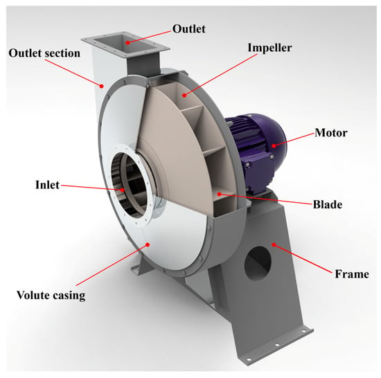
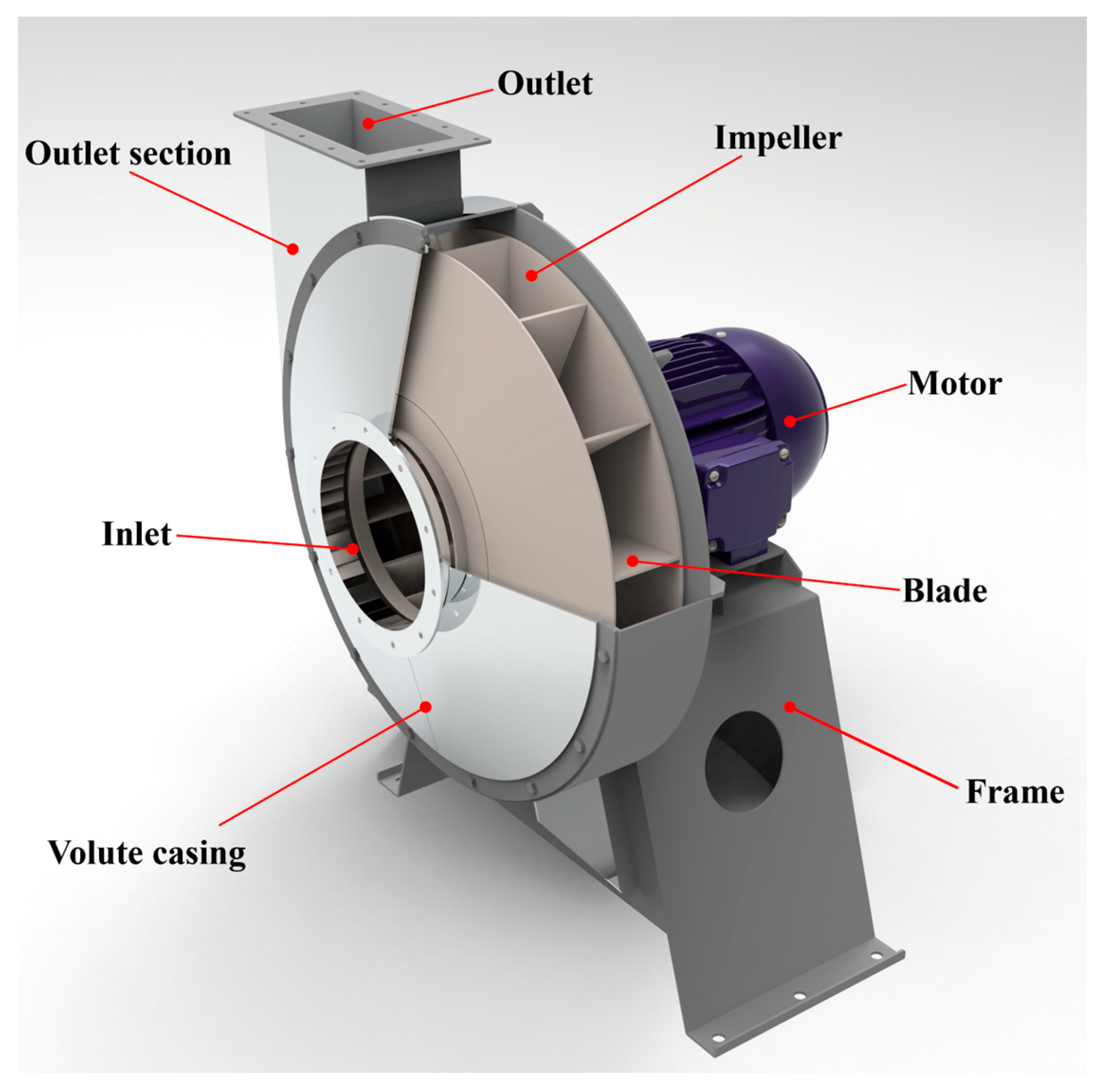
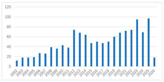
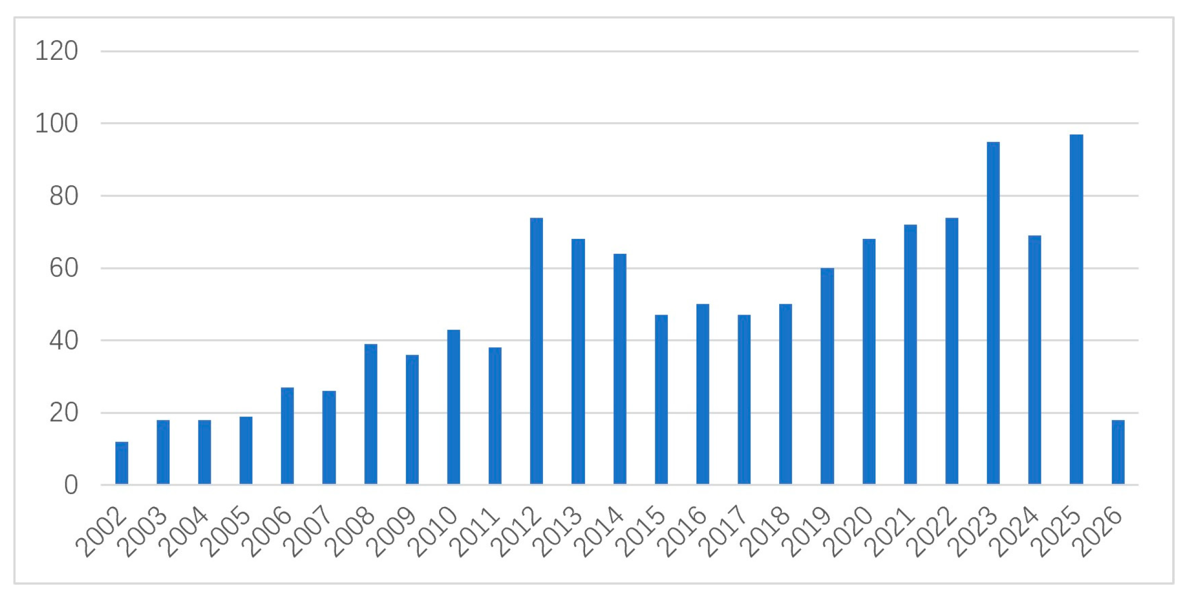
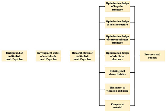
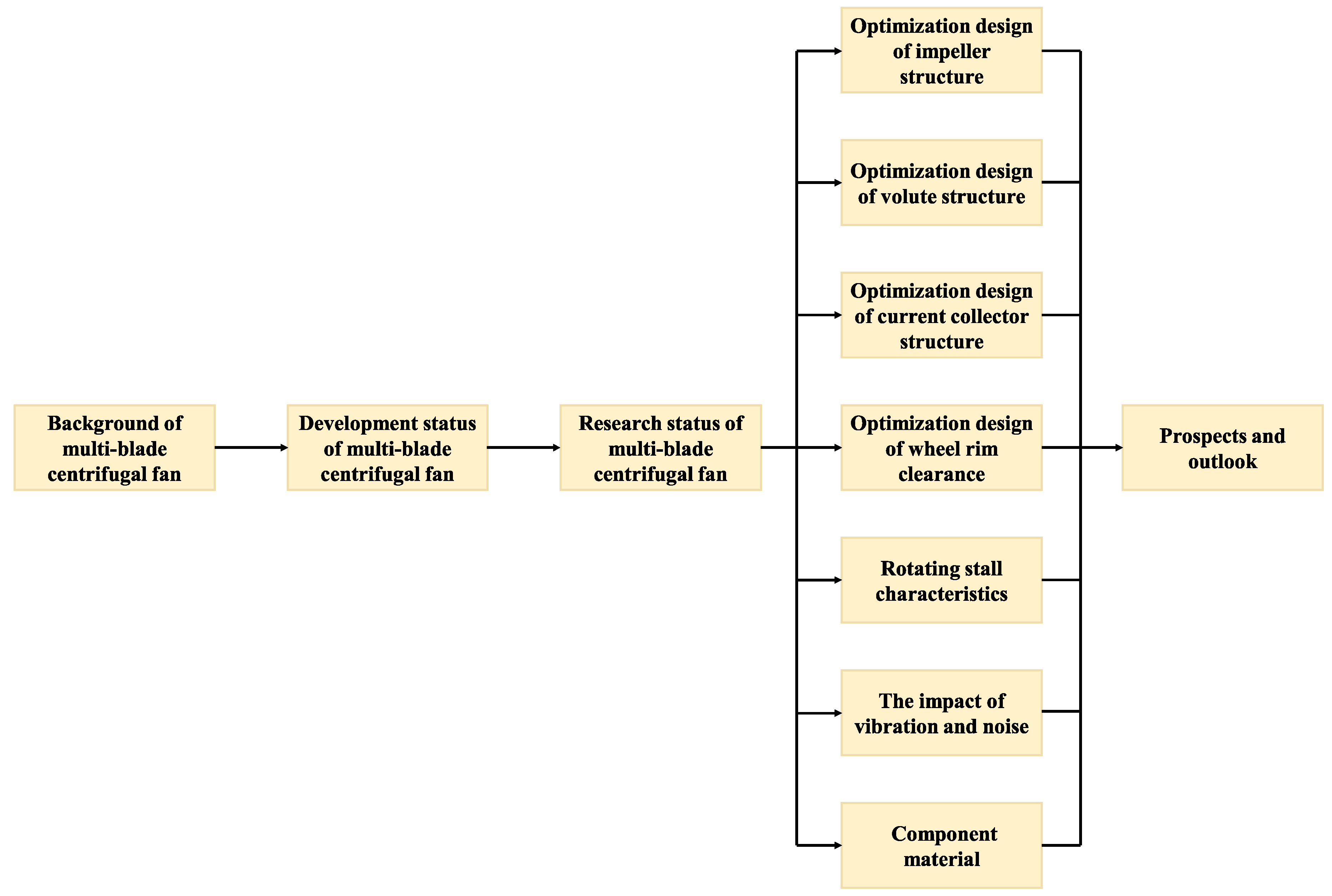
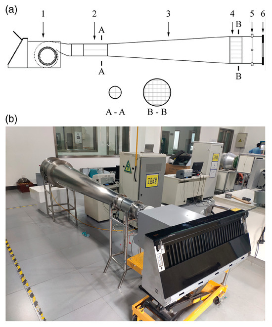
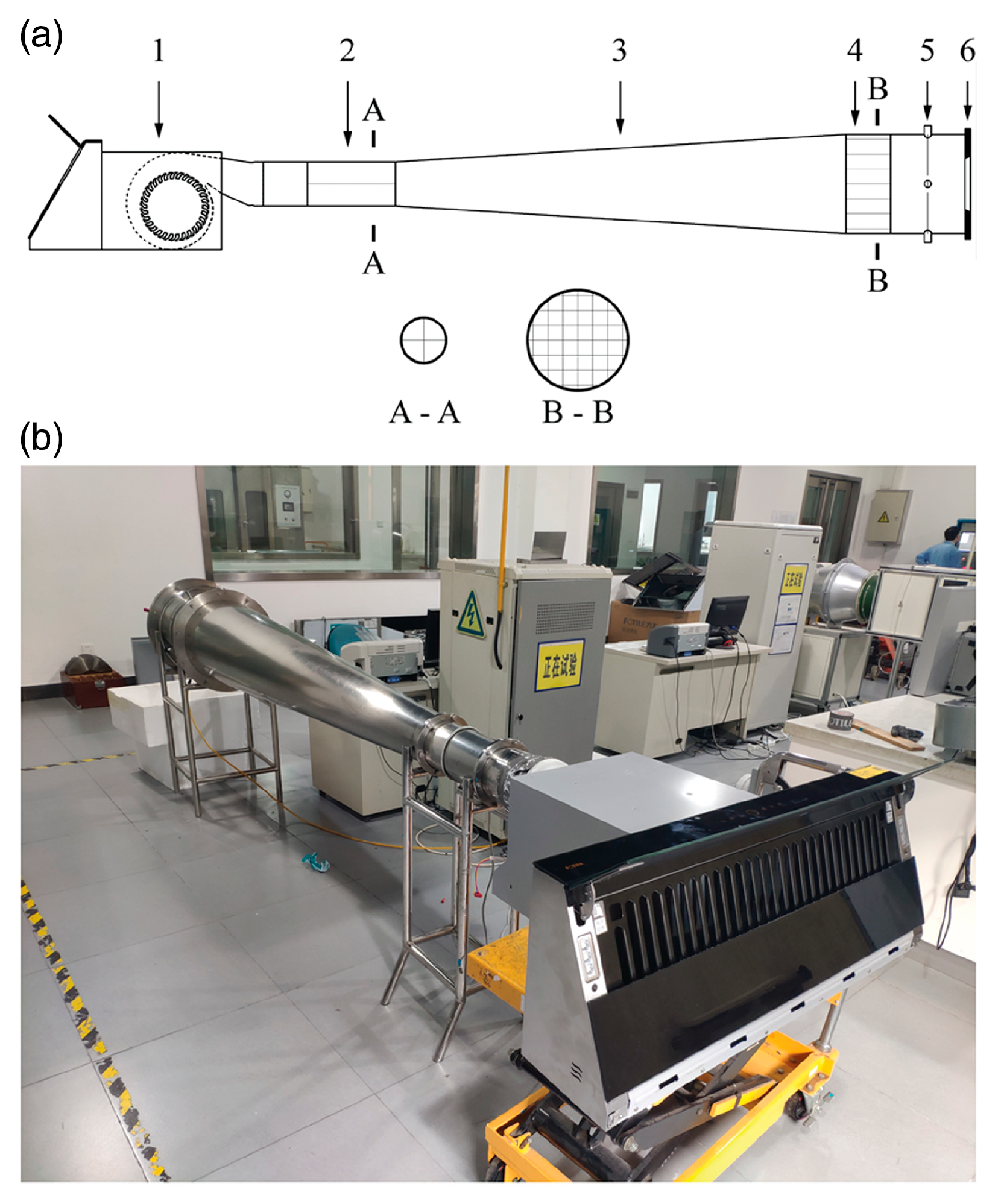
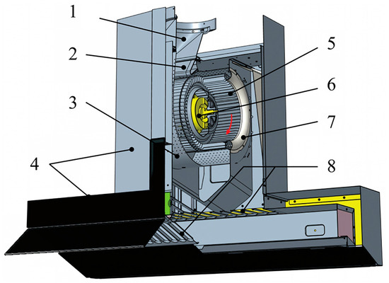
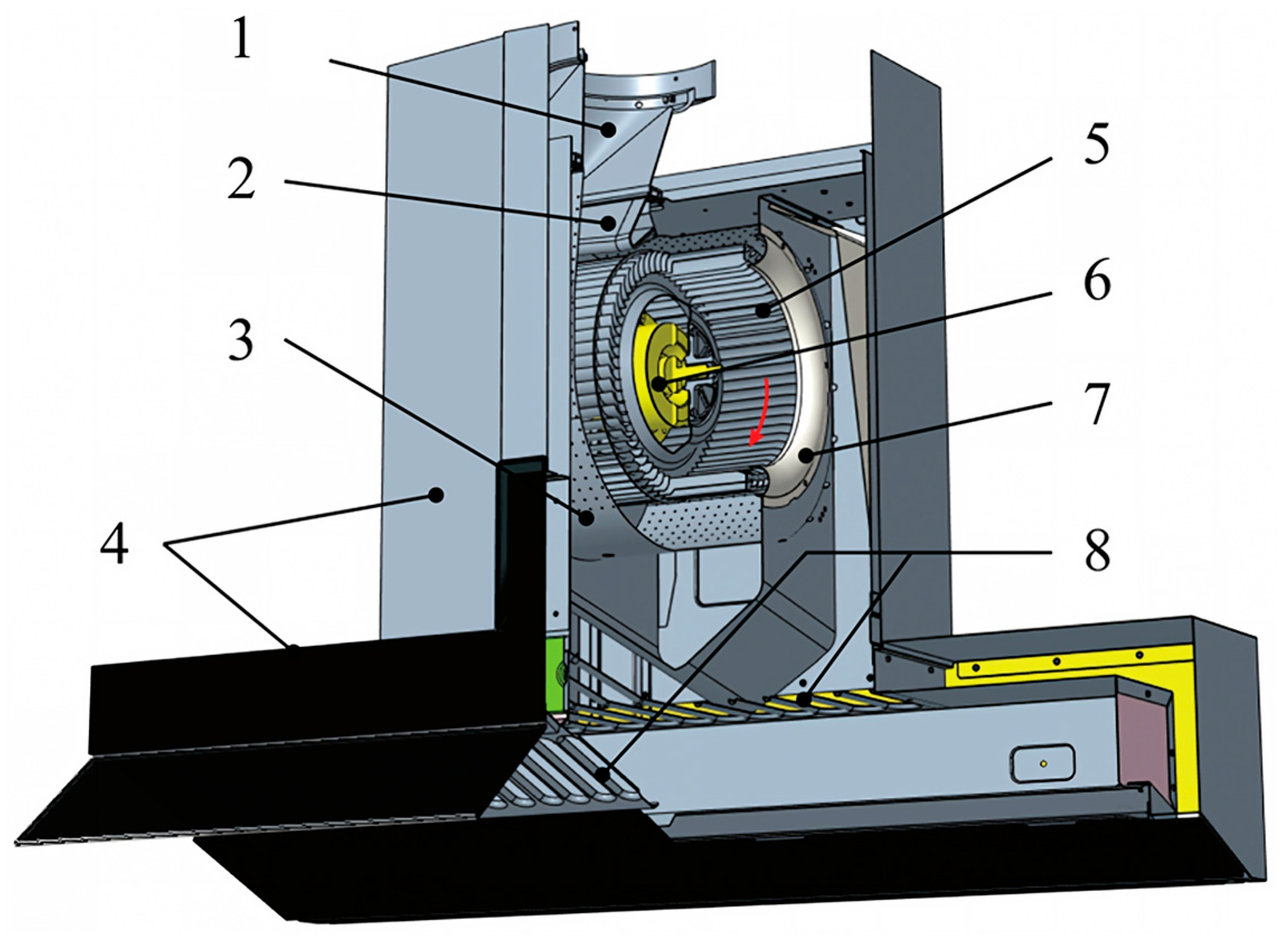
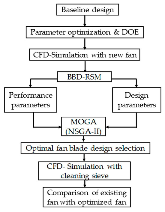
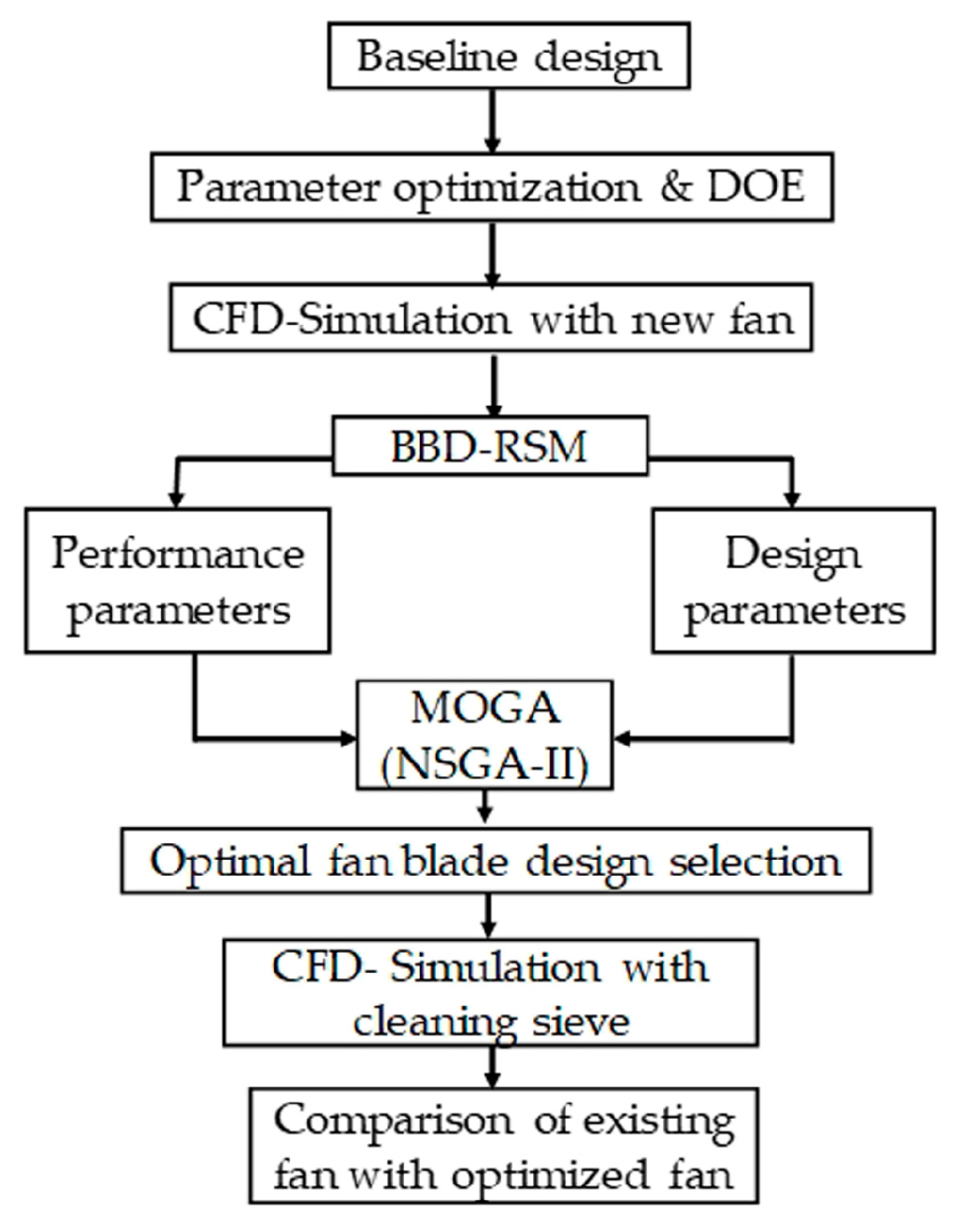
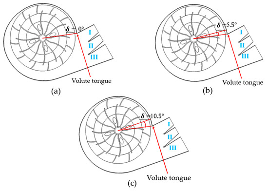
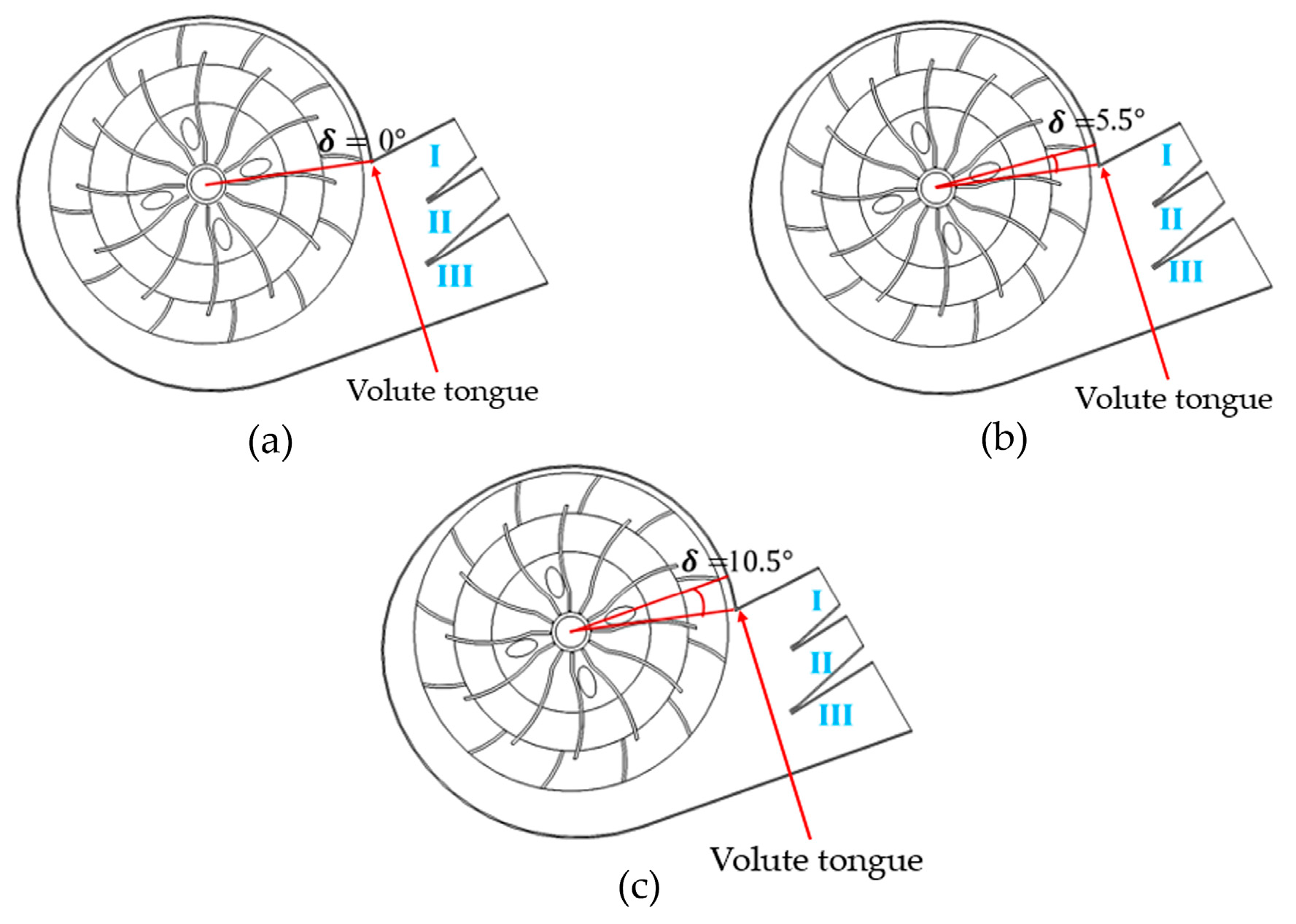
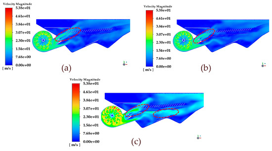
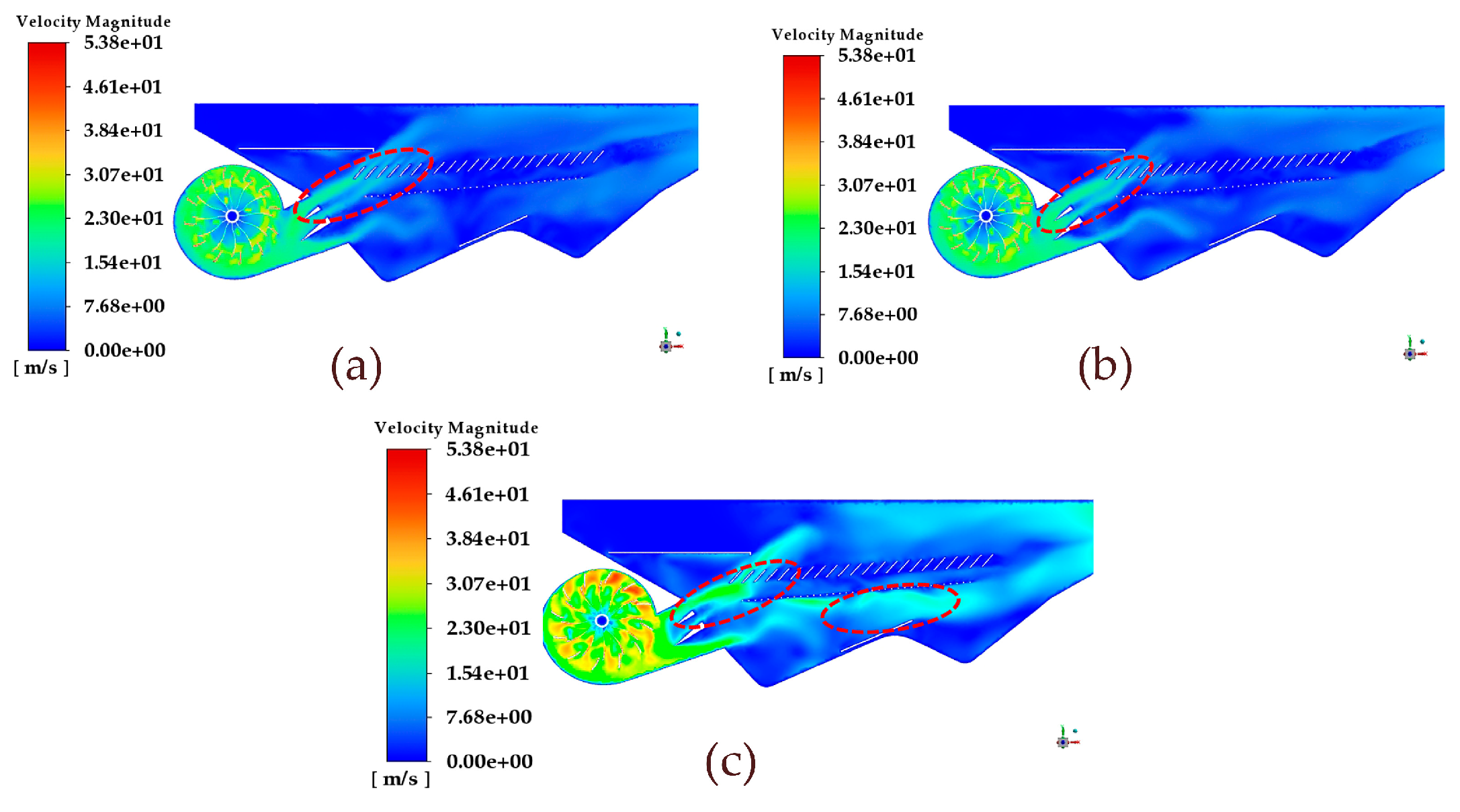
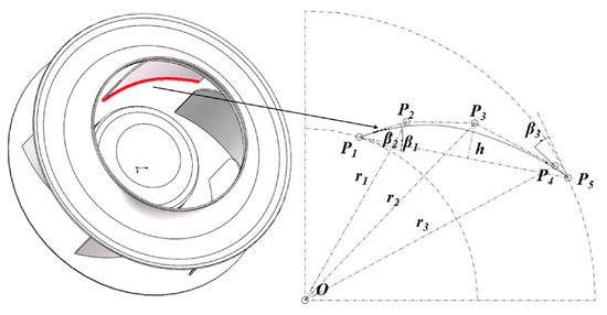
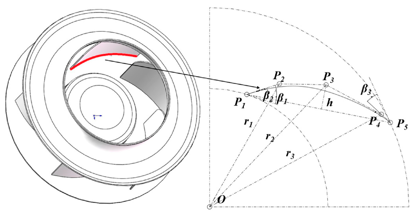
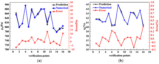

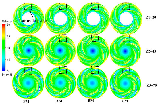
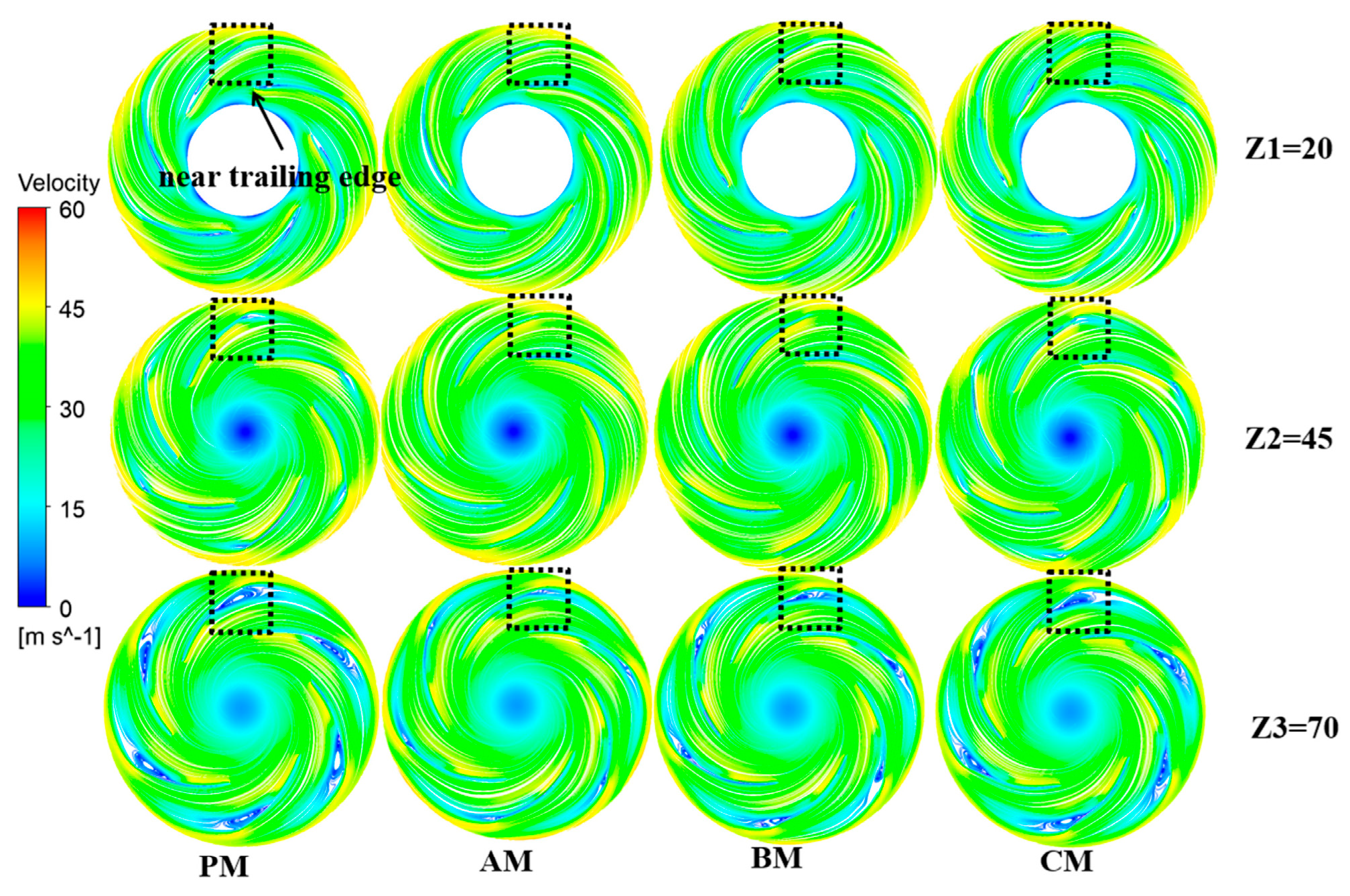
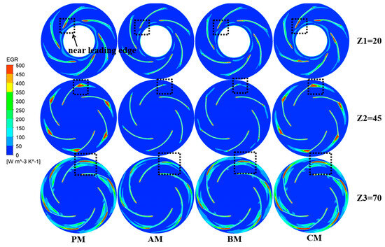
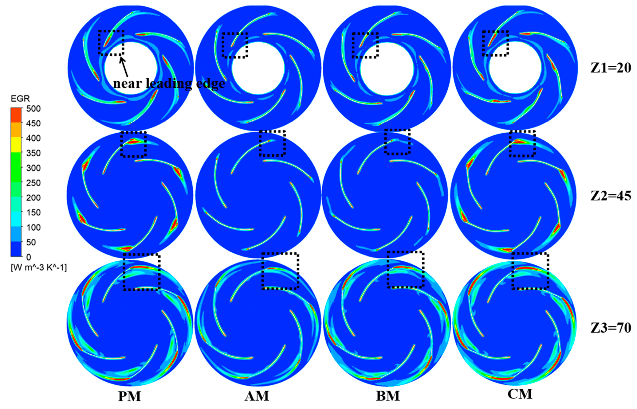
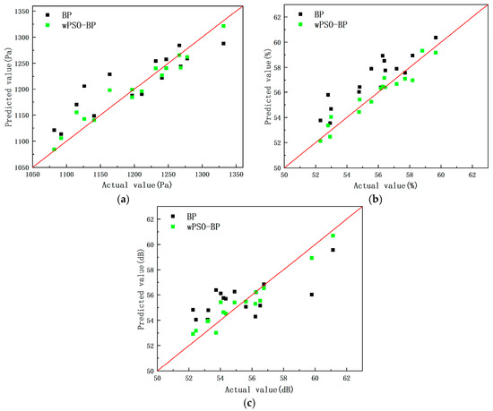
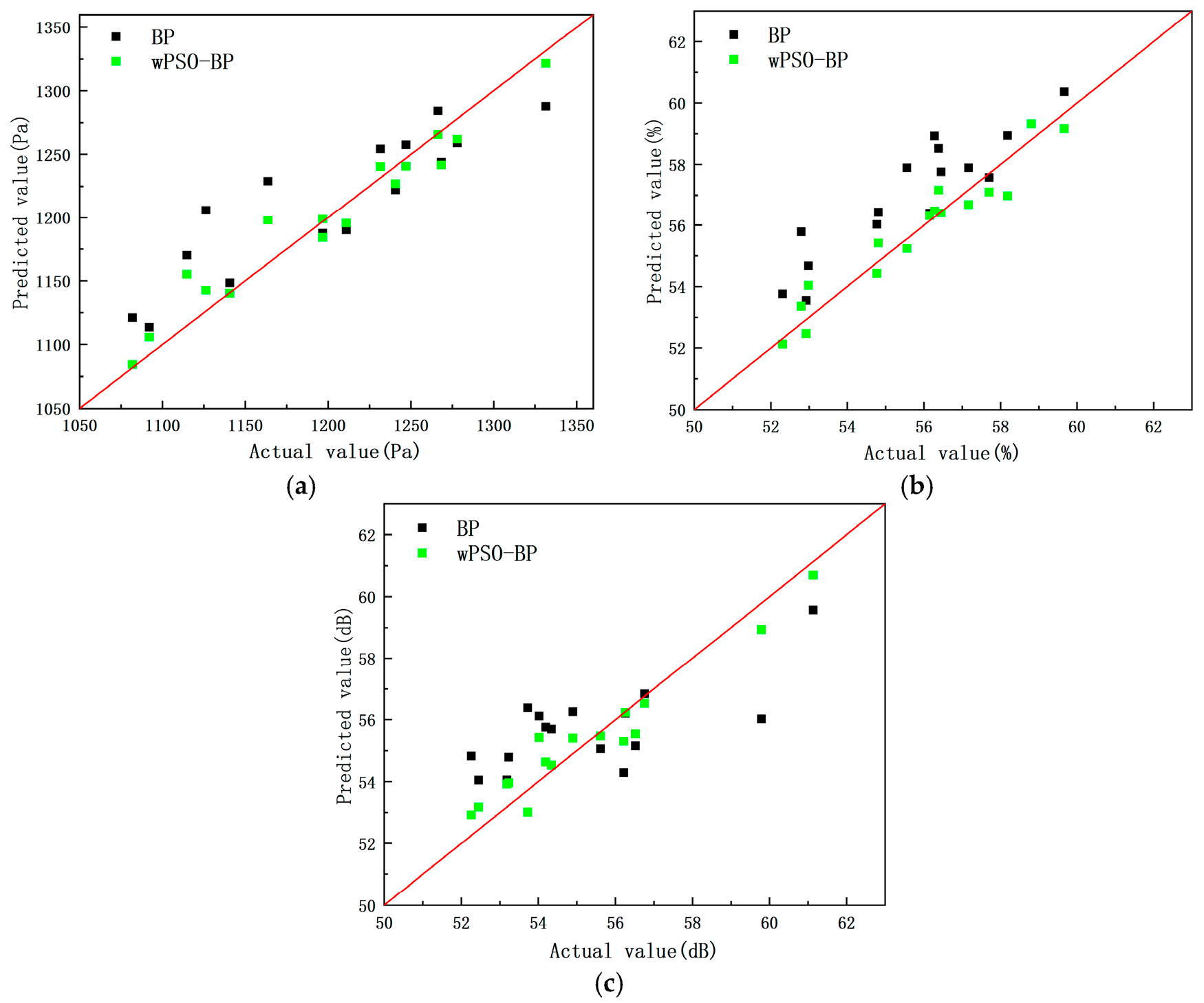
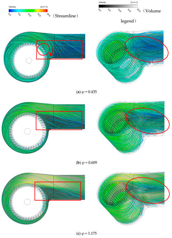
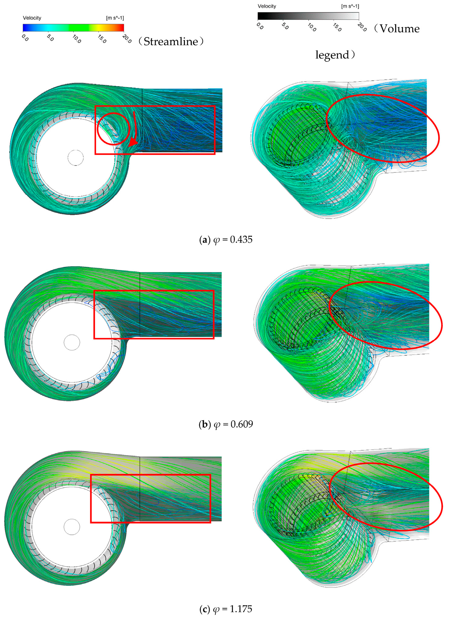
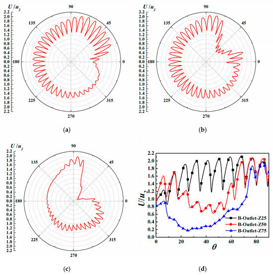
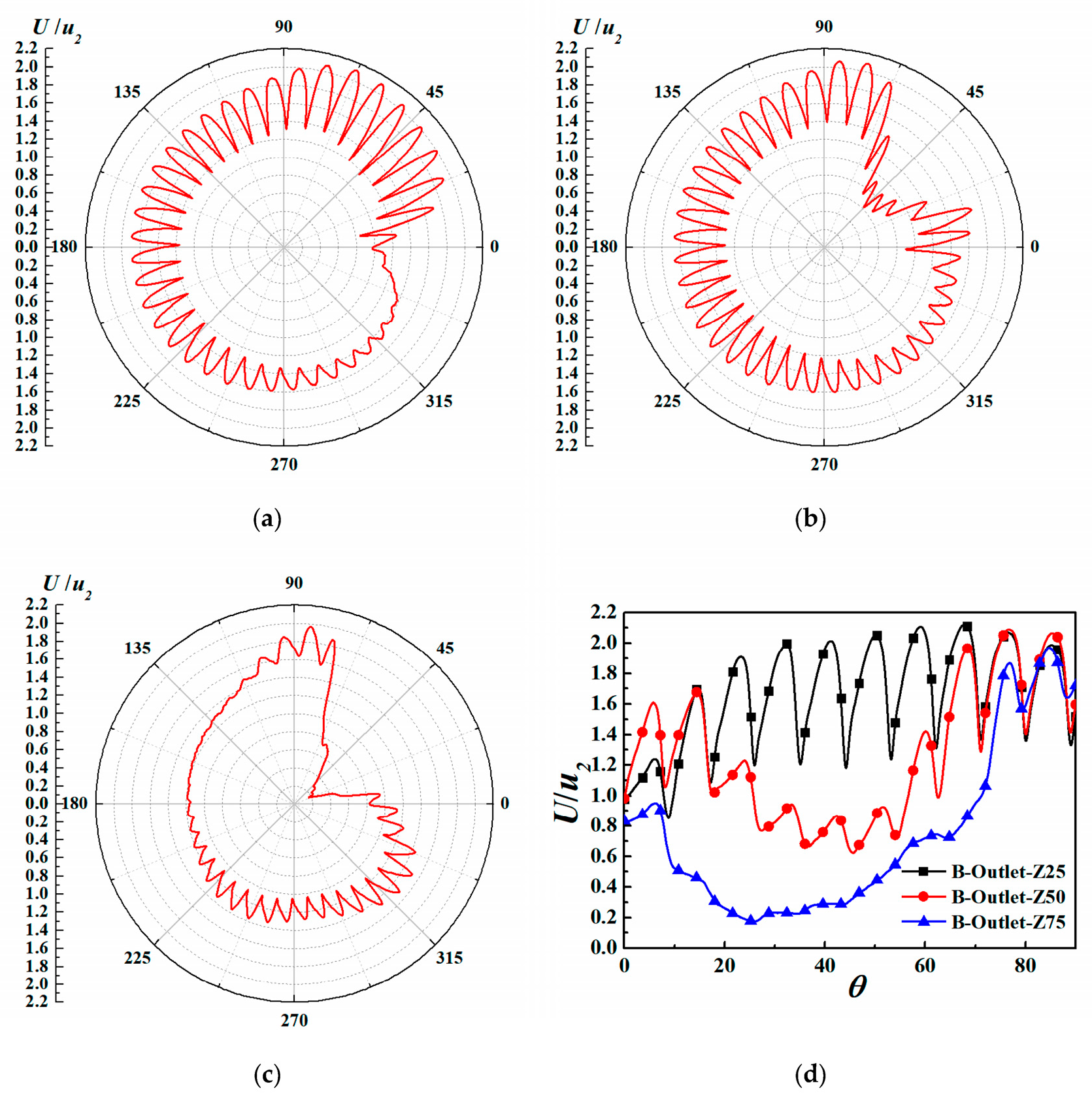
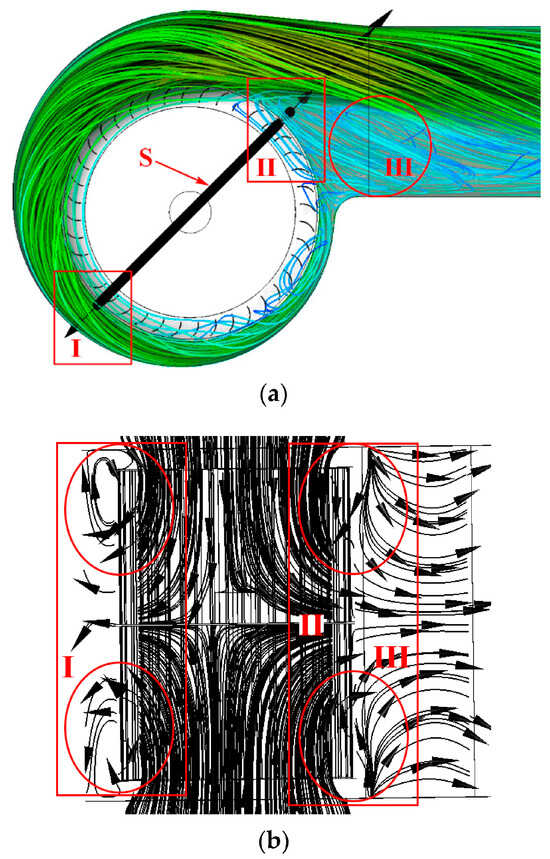
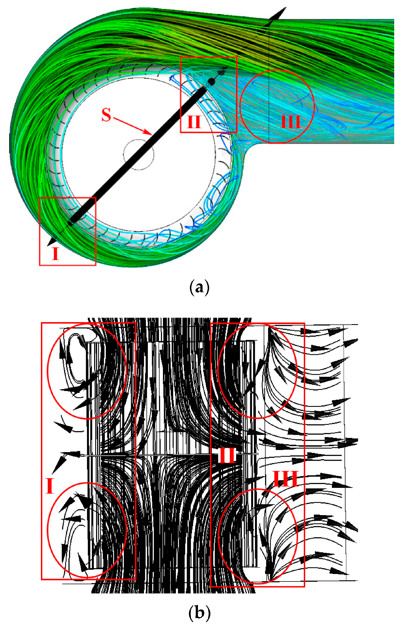
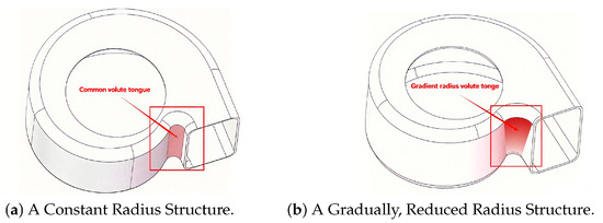
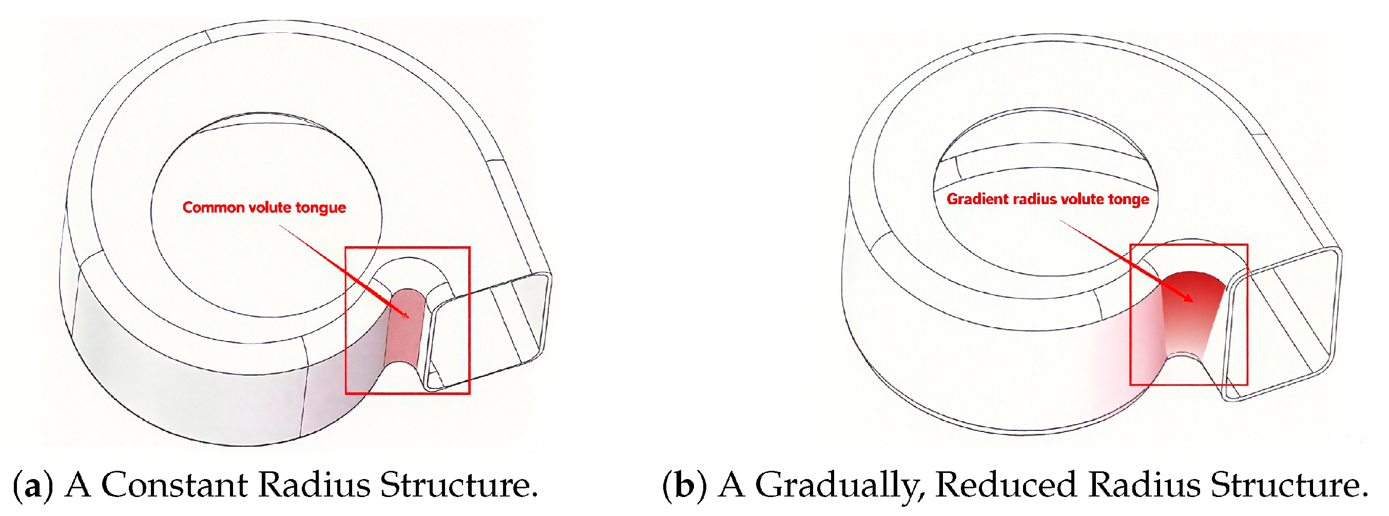
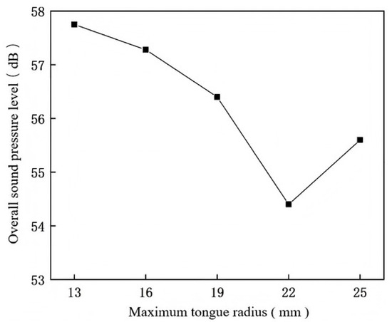
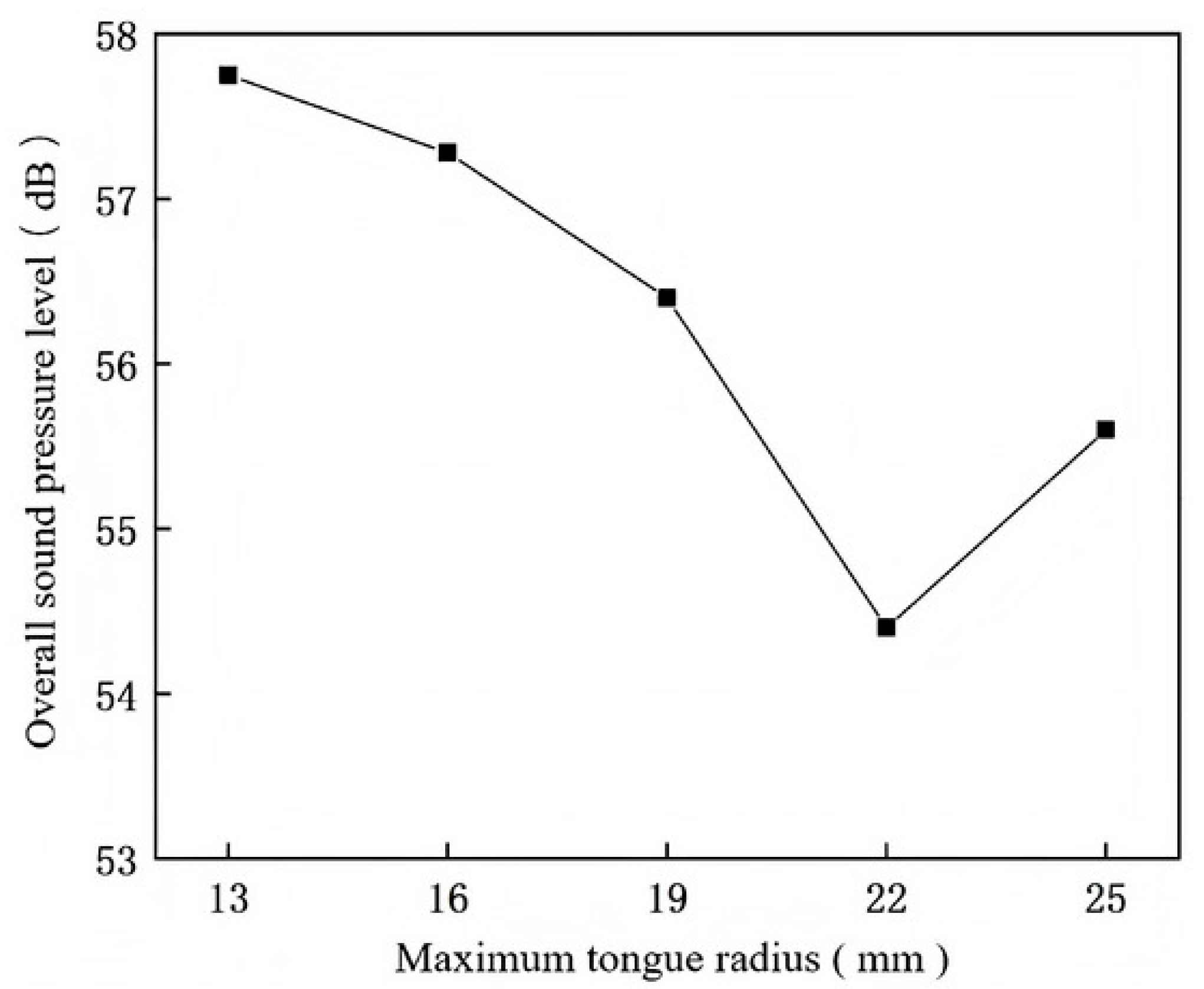
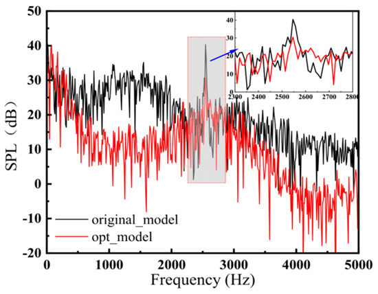
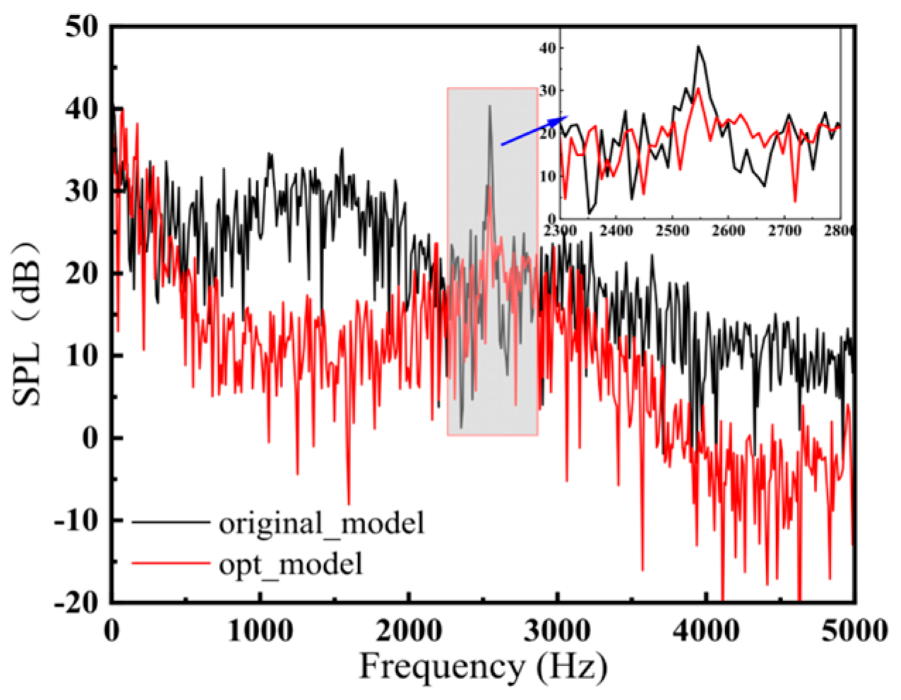
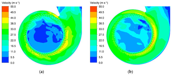
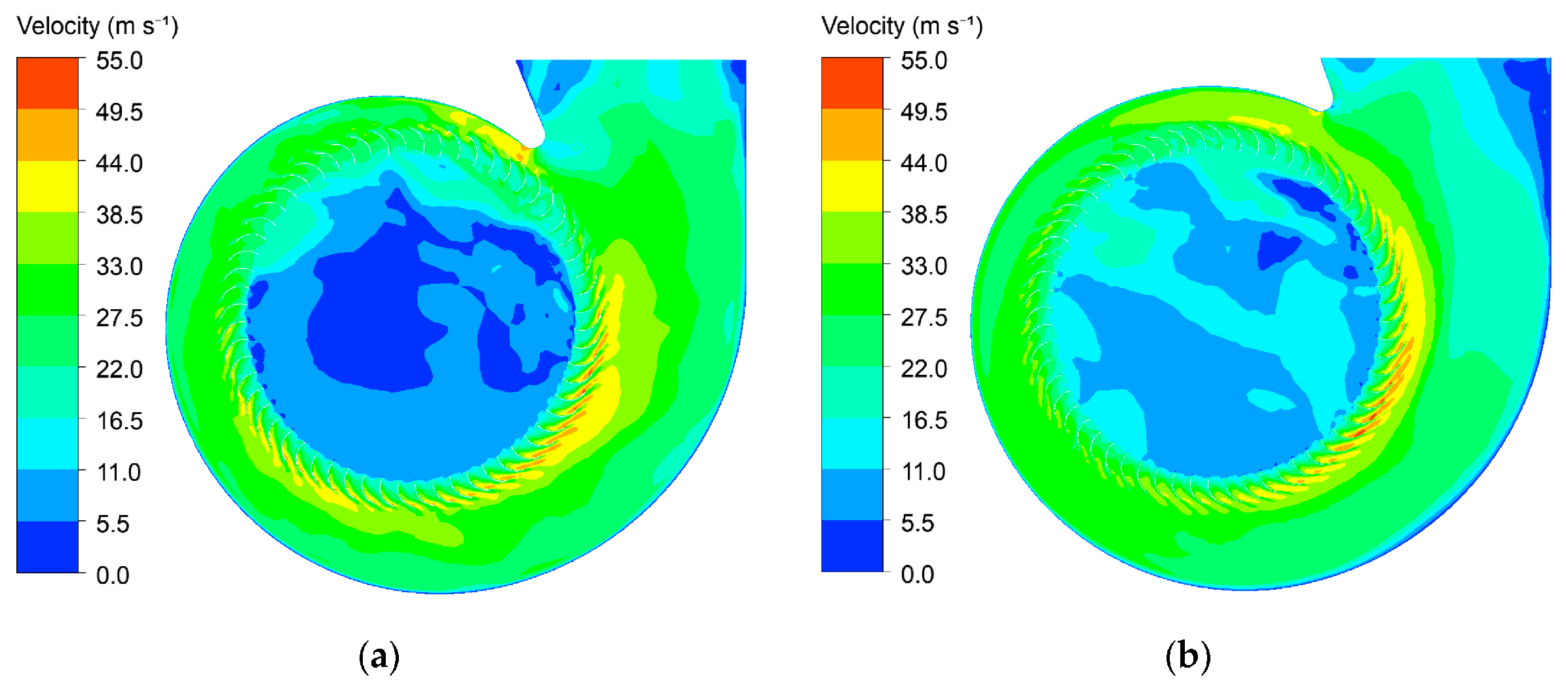
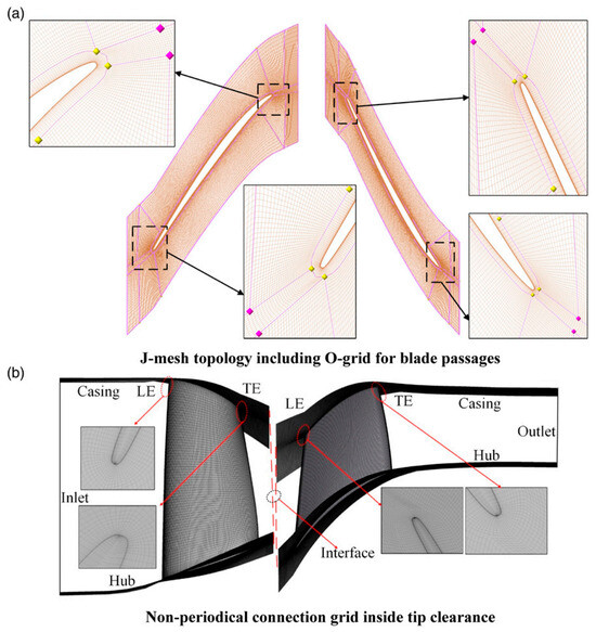
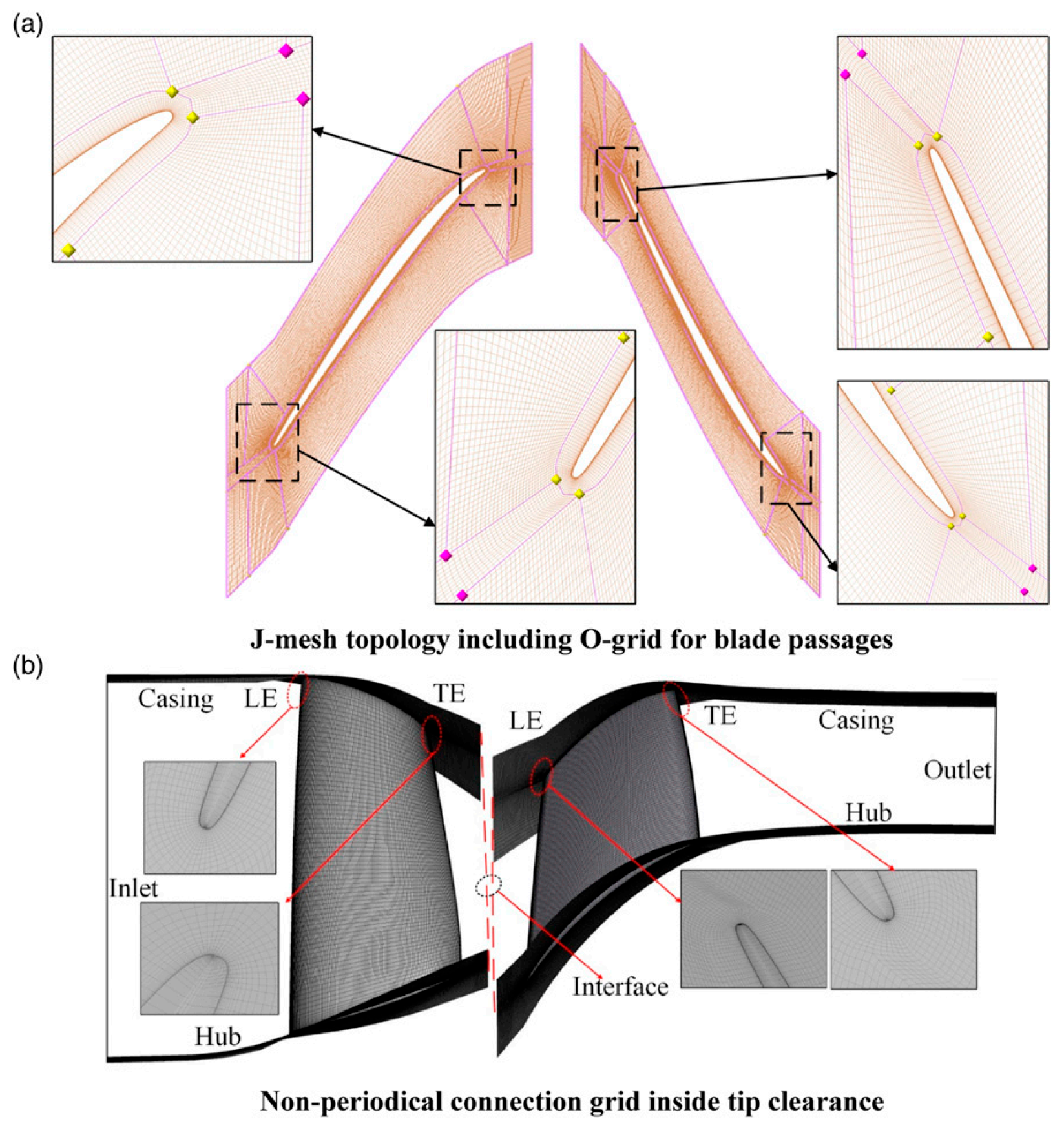
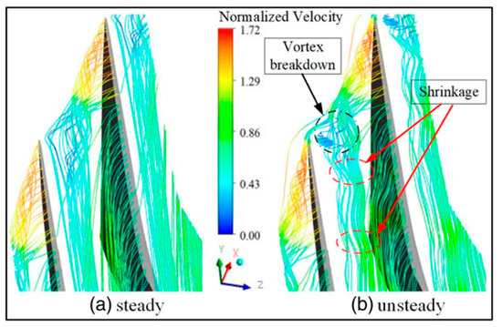
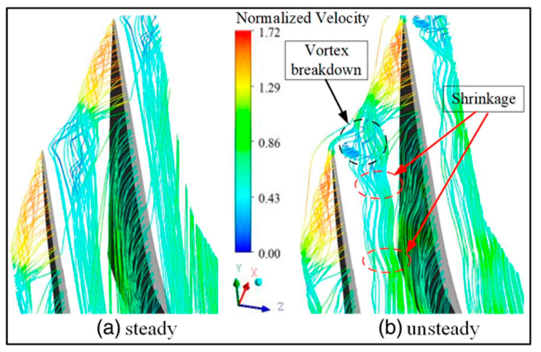
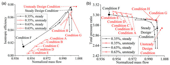
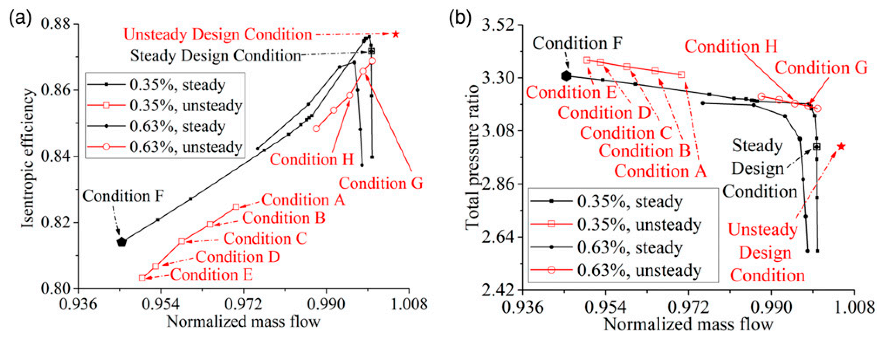
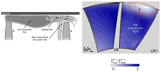
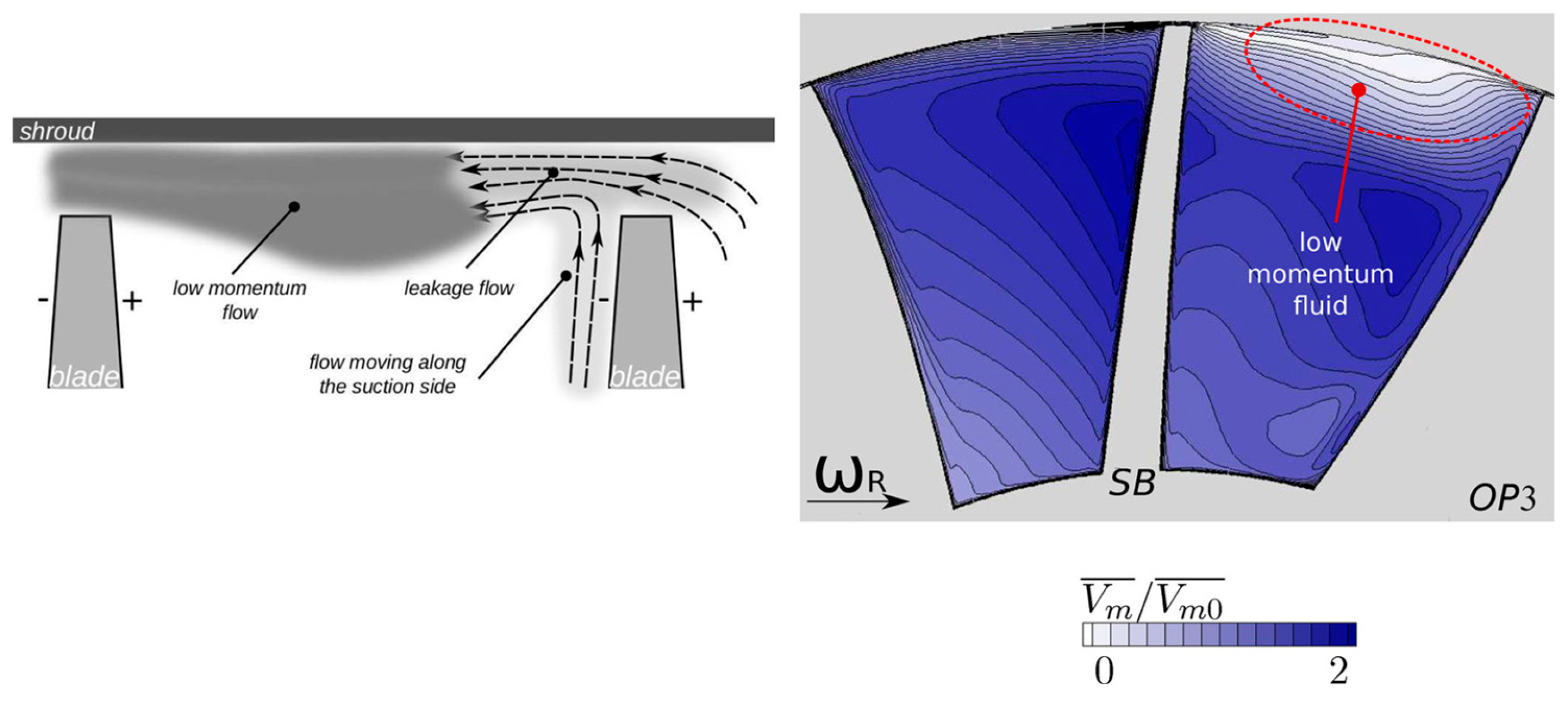
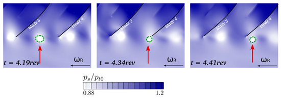
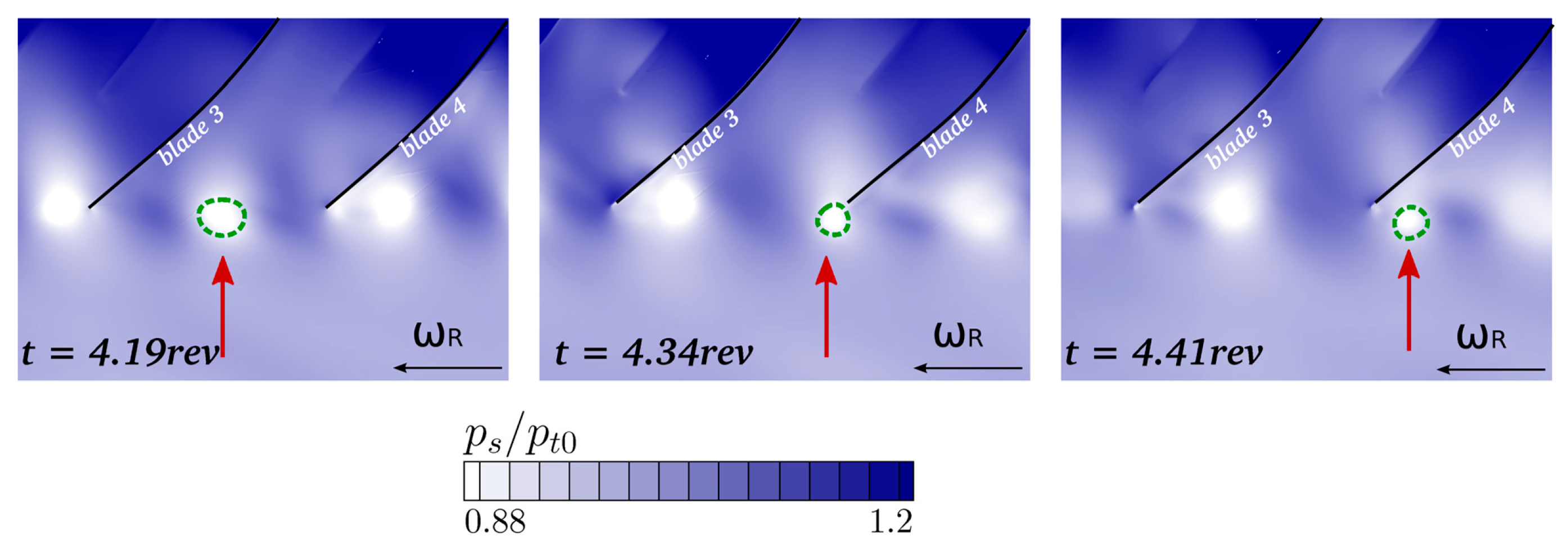

Disclaimer/Publisher’s Note: The statements, opinions and data contained in all publications are solely those of the individual author(s) and contributor(s) and not of MDPI and/or the editor(s). MDPI and/or the editor(s) disclaim responsibility for any injury to people or property resulting from any ideas, methods, instructions or products referred to in the content. |
© 2026 by the authors. Licensee MDPI, Basel, Switzerland. This article is an open access article distributed under the terms and conditions of the Creative Commons Attribution (CC BY) license.