


Abstract
Nonsmooth gear-contact vibration under variable-speed operation is strongly affected by mesh-phase evolution, backlash-induced contact switching, and unilateral tooth contact. This study investigates local line-of-action vibration suppression in a single-stage spur-gear pair performing a repetitive acceleration–braking–cruising task. The modelling contribution is a control-oriented hybrid-coordinate formulation that separates the prescribed mean-speed motion from local dynamic transmission error (DTE), reconstructs the time-varying mesh stiffness (TVMS) phase from the mean angle and local relative displacement, and retains a distinct mean-coordinate phase for transmission error (TE). The learning contribution is a bounded line-of-action force strategy that combines finite-time application, low-pass filtering, plateau DC removal, amplitude and rate constraints, and trial-level contact-response acceptance and rollback. Thus, an input-feasible candidate can still be rejected when its executed contact response violates the prescribed limits. Under the nominal same-initial-condition baseline, the trade-off iteration reduces DTE and mesh-force AC RMS by 11.52% and 24.85%, respectively. Contact loss decreases from 3.35% to 0.55%, and re-engagements decrease from 29 to 5. In 100 paired perturbation samples, 94 cases improve both RMS measures. The results support the proposed framework within the tested numerical task and perturbation range.
1. Introduction
Gear transmissions in vehicle drivetrains, robots, machine tools and compact electromechanical actuators must maintain motion accuracy while limiting dynamic tooth loads and vibration [1,2,3]. This requirement becomes especially demanding during repeated acceleration, braking and low-speed cruising. Because rotational speed varies continuously, the mesh frequency changes and the mechanical phase no longer advances at a constant rate; at the same time, backlash and unilateral tooth contact can interrupt and restore load transfer [4,5,6,7,8,9]. The response is consequently both time-varying and nonsmooth.
Dynamic transmission error (DTE) and mesh force characterize complementary aspects of the local meshing response. DTE represents relative line-of-action displacement and is closely associated with vibration excitation, whereas mesh force reflects the transmitted tooth load and its dynamic variation [2,4,8]. Under variable-speed operation, time-varying mesh stiffness (TVMS), transmission error (TE), backlash and contact damping can produce contact loss and isolated re-engagement impacts [5,6,7,9,10,11]. Because no single metric captures both continuous fluctuations and event-driven peaks, the AC root-mean-square (RMS) values are evaluated together with the contact-loss rate and re-engagement count.
Phase treatment is an important modelling issue. Constant or fixed-time-period TVMS descriptions can be adequate near steady speed, where time and angular displacement are almost linearly related [5,6,10,11]. During acceleration, braking and low-speed transitions, however, tooth entry, tooth exit and re-engagement follow mechanical phase rather than an assumed time period. A fixed-time waveform can therefore misalign stiffness extrema, TE excitation and contact events with the corresponding tooth-pair phases. Previous transient gear-dynamics work has shown that variations in rotational speed and external excitation alter the mesh excitation and dynamic response [7], while the cited stiffness studies primarily develop or review mesh-position-dependent stiffness and contact formulations [10,11,12]. The model-level novelty of the present work therefore does not lie in introducing angularly varying mesh stiffness alone. Rather, it lies in a control-oriented hybrid-coordinate construction that separates the prescribed mean-speed motion from the local line-of-action dynamics, uses the local relative displacement to correct the reconstructed TVMS phase while retaining a distinct mean-coordinate phase for TE, and provides a local force-balance channel for compensation without modifying the prescribed speed task.
The contact law must also represent the nonsmooth response. Backlash creates a dead zone in the effective clearance coordinate, whereas unilateral tooth contact must release rather than transmit tensile normal force [5,6,9,13,14]. Contact loss, side switching and re-entry should therefore emerge from the state-dependent model instead of being imposed as external disturbances. This distinction matters in control assessment: a compensation signal may improve an averaged displacement measure while unloading the preload or producing a small number of severe impacts.
The actuation channel likewise needs to be consistent with the control objective. Speed controllers act through a mean acceleration or torque channel and are designed primarily for trajectory-level regulation [15]. By contrast, local DTE and mesh force depend on relative line-of-action motion, TVMS, TE, backlash and the active contact side [2,5,6,8,9,16]. The comparison between speed-channel feedback and line-of-action compensation is therefore used to examine channel–objective alignment.
Iterative learning control (ILC) exploits task repeatability by converting information from one trial into feedforward action for the next [17,18,19]. Input-constrained ILC formulations show how this learning process can be combined with feasibility limits [20,21]. In gear-contact applications, however, switching, saturation and impact-like transients can make unrestricted full-horizon updates unsafe and lead to nonmonotonic performance. Conventional input-constrained ILC determines the admissibility of a candidate update mainly in the input domain through feasibility, amplitude, and rate limits. For nonsmooth gear contact, however, an input-feasible candidate may still deteriorate the contact state after execution. The proposed contact-event-driven rollback therefore extends the update-admissibility criterion from input feasibility alone to joint input–contact-response admissibility; the projected candidate is retained only when the resulting contact-event and response measures remain within their prescribed limits. Otherwise, the learning sequence is restored to the most recently accepted input.
Recent studies have extended the analysis of nonstationary transmission dynamics and advanced vibration control. Electromechanical models of geared electric-drive systems have considered steady, accelerating, variable-speed, and variable-load conditions, while recent spur-gear studies under time-varying rotation speeds have related speed evolution to changing mesh-cycle duration, transient DTE, and mesh-force response [22,23]. For vibration suppression in geared electric-drive systems, harmonic-current compensation, active-disturbance-rejection current compensation, and double-layer model-predictive control have been investigated [24,25,26]. In parallel, data-driven vibration-control research has increasingly emphasized data-informed feedforward design, input shaping, performance evaluation, and engineering implementation [27]. These developments provide a contemporary context for the present study, which focuses on bounded trial-to-trial line-of-action force learning for nonsmooth gear contact under a repeatable variable-speed task.
Against this background, the novelty of the present study does not lie in phase-dependent TVMS or input-constrained ILC considered separately. It lies in their control-oriented integration for repetitive variable-speed nonsmooth gear contact. First, the hybrid-coordinate model separates the prescribed mean-speed motion from the local line-of-action dynamics, reconstructs the TVMS phase from the mean angle and local relative displacement, and retains a distinct mean-coordinate phase for TE. Second, the bounded force-learning method combines finite-support input shaping and amplitude rate projections with a trial-level contact-response acceptance and rollback rule, so an input-feasible candidate is not retained if its executed contact response violates the prescribed limits. Third, a same-initial-condition performance–input-cost protocol, matched same-channel learning baselines, and paired perturbation tests are used to distinguish the nominal benefit of line-of-action learning from the supervisory role of rollback and to define the tested range of the conclusions.
2. Materials and Methods
2.1. Phase-Consistent Hybrid-Coordinate Dynamic Model
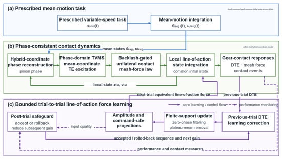
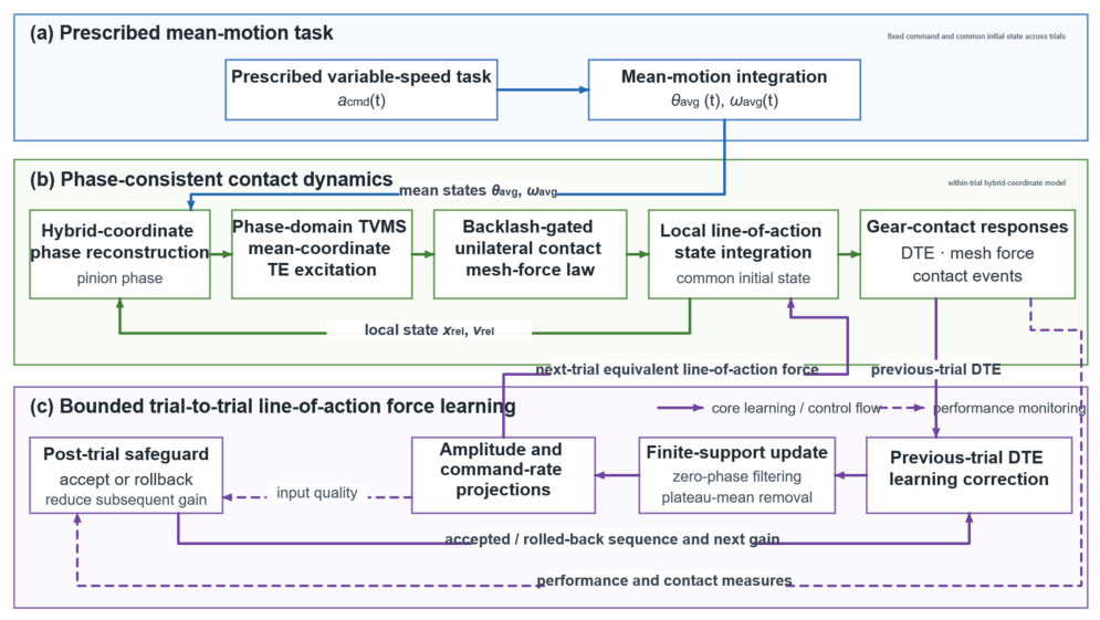
Figure 1 shows the separation between the prescribed mean-motion task and the local contact-vibration loop. The mean-coordinate channel advances mean angular displacement and velocity, while the contact channel reconstructs the phase variables and combines TVMS, TE, backlash, contact gating and the unilateral force law before numerical integration. After each trial, DTE, mesh-force and contact-event measures enter the CF-ILC update and acceptance/rollback rule. The accepted sequence returns to the next trial only as an equivalent line-of-action force. This architecture preserves the prescribed mean-speed task and directs compensation to the local force balance that generates the reported vibration metrics.
Figure 1.
Phase-consistent modelling and bounded line-of-action force-learning framework. CF-ILC, constrained-force iterative learning compensation; DTE, dynamic transmission error; TE, transmission error; TVMS, time-varying mesh stiffness.
2.1.1. Vibration-Oriented Modelling Assumptions and Generalized Coordinates
The plant is a control-oriented, reduced-order representation of a single-stage external spur-gear pair. At the system level, it represents one local gear-mesh stage within a larger electromechanical drivetrain, rather than a complete drivetrain or vehicle model. It resolves the dominant relative motion along the line of action, with the pinion and gear inertias projected onto this coordinate. The imposed mean-coordinate acceleration generates the repeated speed task, while CF-ILC acts only in the relative force-balance equation.
The hybrid-coordinate state vector is defined as:
where and are the relative displacement and relative velocity along the line of action, respectively. In this control-oriented model, is used as the DTE coordinate. Variables and denote the mean angular displacement and mean angular velocity used to advance the prescribed speed task and the mesh phase. All relative displacements, velocities, forces, and control inputs in the local vibration channel are expressed along the line of action.
The base-circle radii of the pinion and gear, and the equivalent inertia projected onto the line of action, are written as:
where m is the module, and are the numbers of teeth of the pinion and gear, respectively, is the pressure angle, and and are the rotational inertias.
2.1.2. Hybrid-Coordinate Equations of Motion
The equivalent line-of-action load is modelled as:
where is the static preload, and are coefficients of the speed-dependent load terms, and denotes an optional external disturbance. The hybrid-coordinate dynamic equations are then expressed as:
Here, denotes the nonlinear mesh force jointly generated by the phase-domain stiffness, transmission error, backlash dead zone, contact-state gating, and unilateral contact law. is the active equivalent compensation force along the line of action.
2.1.3. Phase-Consistent Mesh Stiffness and Transmission Error
Under variable-speed operation, mesh stiffness is expressed as a function of mechanical mesh phase rather than as a function of a fixed time period [6,10,11,12]. The stiffness term uses a pinion phase reconstructed from the hybrid-coordinate state as follows:
The time-varying mesh stiffness is represented by a Fourier-type phase-domain function,
The lower bound in Equation (7) prevents the harmonic superposition from producing negative or unreasonably low stiffness values. It applies only to the potential stiffness function; whether the tooth pair is in contact remains governed by the contact law.
The transmission error (TE) enters the contact boundary as an internal displacement excitation, and its phase is constructed from the mean angular coordinate.
Here, phase consistency refers to the parametrization of the periodic mesh terms rather than to the integration variable of the dynamic equations, which remains time. Each periodic term is advanced by the angular coordinate associated with its physical role instead of by a prescribed fixed time period. At constant speed, the two descriptions are nearly equivalent because angular displacement increases almost linearly with time. During acceleration or braking, however, a fixed-time waveform continues to repeat at its preset period, whereas the phase-consistent waveform is compressed or stretched in time as the rotational speed changes. Consequently, the stiffness extrema and TE excitation remain tied to the corresponding tooth-pair positions rather than to predetermined time instants. In the present formulation, TVMS uses the reconstructed pinion phase in Equation (5), whereas TE uses the mean-coordinate mesh phase in Equation (8); phase consistency therefore does not require the two terms to share an identical phase variable.
2.1.4. Backlash Dead Zone, Contact Gating, and Unilateral Mesh Force
The effective clearance coordinate is obtained by subtracting the transmission error from the line-of-action relative displacement:
Backlash is represented by a piecewise-linear dead-zone function:
where is the half-backlash width. The signed dead-zone output denotes the effective contact deformation after the clearance boundary is crossed. When , the tooth pair is inside the backlash dead zone and transmits no normal mesh force.
The unilateral normal contact force and signed mesh force are then written as:
Equation (14) enforces unilateral transmission, the active flank carries a compressive normal force, whereas any tensile trial force is clipped to zero. Because the entire normal-force expression is multiplied by the contact flag, damping contributes to the mesh force only while contact is active. The separated-state coefficient in Equation (13) therefore generates no force during contact loss. Contact loss, re-engagement, and side switching emerge from the state-dependent law rather than being imposed as disturbances.
2.1.5. Repetitive Variable-Speed Task and Initial Conditions
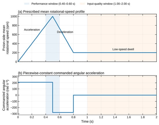
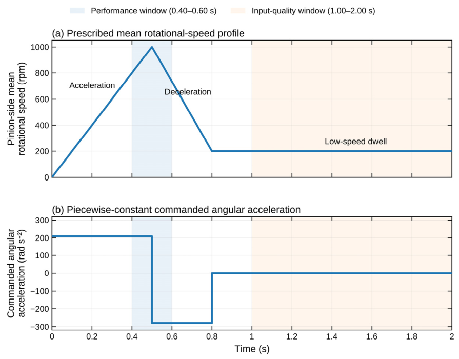
The prescribed mean-speed task consists of three stages: acceleration from rest to 1000 rpm over ; braking from 1000 rpm to 200 rpm over ; and cruising at 200 rpm over . Let , , s, and s. The prescribed mean-coordinate acceleration is:
The three-stage schedule was selected as a compact subsystem-level duty cycle representing repeated run-up, commanded deceleration, and subsequent low-speed operation in geared electromechanical drives. The high- and low-speed levels differ by a factor of five, producing a substantial change in mesh frequency while the direction of rotation remains unchanged. The transition from positive to negative commanded mean acceleration therefore permits the contact response to be examined during evolving mesh phase and frequency without introducing rotational reversal as an additional factor. The final low-speed stage represents continued operation after deceleration and also provides a common post-transient interval. Combining the three stages in one prescribed trial ensures that the complete task can be repeated identically for iterative learning.
To prevent differences in the initial contact state from confounding the performance comparison, every repetitive trial begins from the same preload-equilibrium initial condition:
For the nominal parameters, and ; therefore, . This same-initial-condition setting provides a consistent baseline for the subsequent iteration, actuation-channel comparison, ablation, and robustness studies.
2.2. Bounded Line-of-Action Force Learning for Active Vibration Suppression
2.2.1. Vibration-Suppression Objective and Feedback Variable
CF-ILC is designed to suppress the alternating local response rather than drive DTE to zero. Static preload and backlash establish a non-zero load-bearing equilibrium, making it physically inappropriate to force the displacement coordinate to zero. The reported objectives are the AC components of DTE and mesh force, together with contact-loss and re-engagement measures evaluated over the mid-transient window. The learned line-of-action force does not alter the prescribed mean-speed task.
The equivalent line-of-action force serves as the plant input:
Equation (18) defines the control input at the reduced-order coordinate level. For a specified drivetrain, this generalized force must be mapped back to shaft torques through the same coordinate transformation used to project the shaft dynamics onto the line of action. The corresponding torque magnitudes scale with the base-circle radii and , while their signs and allocation depend on the shaft-angle convention and actuator arrangement. With two controllable shafts, coordinated torque modulation can be assigned primarily to the relative-motion channel. With a single motor, the modulation would be superimposed on the mean torque command, and an outer speed loop would be required to maintain the prescribed mean motion.
2.2.2. Windowed Learning and Constrained Update Law
The learning window defines the finite temporal support over which the compensation is updated and applied; it is distinct from the windows used only for performance evaluation. In each update, and denote the most recently accepted input sequence and its corresponding DTE feedback, respectively. The DTE-based learning correction is first multiplied by w and combined with the retained component to form the raw candidate:
The resulting raw candidate is then subjected, in order, to symmetric FFT low-pass filtering with a cutoff frequency of 650 Hz, post-filter windowing by w, removal of the mean over the window plateau, amplitude projection, and sequential projection to enforce the adjacent-sample increment bound:
where is the scalar forgetting factor, is the learning gain, and is the symmetric FFT low-pass operator with . The operator DP subtracts the mean only from the plateau samples in P, leaving the ramp and out-of-window samples unchanged. The operators and denote the amplitude projection and the sequential adjacent-sample increment projection, respectively; hence, is applied before . The superscript “cand” identifies the stored candidate before the trial-level acceptance or rollback decision.
The complete update and execution sequence is summarized in Algorithm 1.
| Algorithm 1. Sequential CF-ILC update and trial acceptance | |
| Input: last-accepted prescribed acceptance limits. | |
| 1: | Compute from Equation (19). |
| 2: | Compute from Equation (20). |
| 3: | |
| 4: | construct using Equation (18). |
| 5: | Execute trial obtain and evaluate the monitored contact and input measures. |
| 6: | if all measures satisfy their acceptance limits then |
| 7: | update according to the accepted-trial rule. |
| 8: | else |
| 9: | reduce according to the rollback rule. |
| 10: | end if |
| Output: retained and updated for the next learning update. | |
2.2.3. Performance Metrics and Representative-Iteration Selection
For a signal in the window Ω, AC RMS is defined as:
The improvement rate, referenced to the same-initial-condition baseline, is defined as:
where M can denote RMS, RMS, DTE peak-to-peak value, or peak-to-peak value. The mid-window RMS score, peak-to-peak score, and residual score are defined as:
Over , the steady-state input cost is defined by normalized high-frequency input RMS and jerk RMS as:
The performance-optimal iteration is the one that minimizes , the peak-to-peak-optimal iteration is the one that maximizes , and the trade-off representative is the candidate with the smallest among those satisfying the mid-window performance threshold. This rule avoids choosing either the last iteration by default or an RMS-optimal iteration with poorer input quality or contact safety.
3. Results and Discussion
3.1. Variable-Speed Task and Evaluation Windows
All controller and perturbation cases follow the same prescribed three-stage mean-speed task shown in Figure 2. The principal mid-transient performance window is 0.40–0.60 s, covering the end of acceleration and the onset of braking, while the steady-state input-cost window is t ≥ 1.0 s. Fixing the task, initial condition and evaluation windows ensures that differences in the operating schedule are not mistaken for vibration suppression.
Figure 2.
Prescribed three-stage variable-speed task and evaluation windows.
The mean speed is prescribed to rise from rest to approximately 104.7 rad/s (1000 rpm) over 0–0.5 s, fall to approximately 20.9 rad/s (200 rpm) over 0.5–0.8 s, and remain at the lower level until 2.0 s. This profile provides a repeatable task with an evolving phase and is not presented as a closed-loop speed-tracking result.
3.2. Nonmonotonic Learning and Representative-Iteration Selection
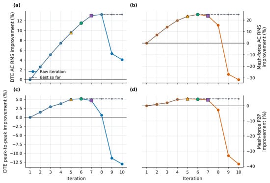
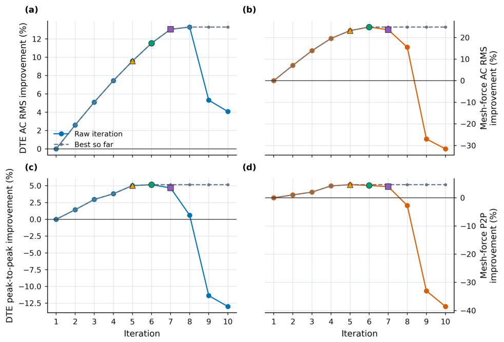
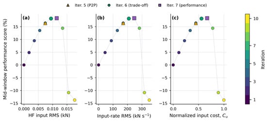
Figure 3 shows improvement over the early trials followed by a rebound, most clearly in the mesh-force RMS and peak-to-peak measures after iteration 7. A more plausible interpretation is the interaction between constraint-induced waveform reshaping and the state-dependent contact dynamics. Although the amplitude projection itself is a convex box operation, its composition with the adjacent-sample increment projection, filtering, and windowing is piecewise nonlinear, and changes in the active constraints can alter the local amplitude, slope, and phase of the learned input. In the backlash system, these waveform changes may shift contact-loss or re-engagement timing and consequently produce nonmonotonic changes in the vibration metrics. The simultaneous increase in the late-iteration input-cost coordinates in Figure 4 is consistent with this interpretation, although the present results do not isolate a unique dominant mechanism. The rebound therefore supports the representative-iteration selection rule rather than automatic use of the final trial.
Figure 3.
Evolution of mid-window vibration metrics during bounded force-learning iterations: (a) DTE AC RMS improvement; (b) mesh-force AC RMS improvement; (c) DTE peak-to-peak improvement; (d) mesh-force peak-to-peak improvement.
Figure 4.
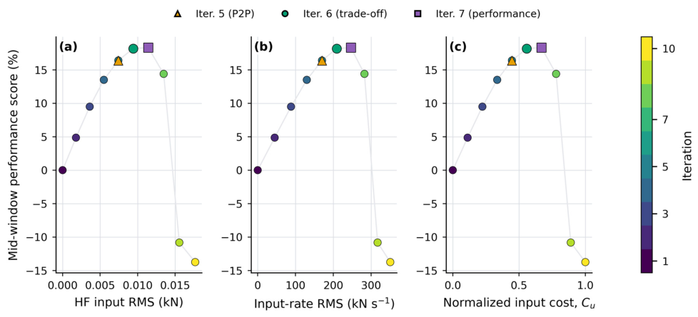
Performance–input-cost relation used to select the trade-off representative iteration: (a) mid-window performance score versus high-frequency input RMS; (b) mid-window performance score versus input-rate RMS; (c) mid-window performance score versus normalized input cost Cu.
In the nominal ten-trial study, the event-aware acceptance layer rejected two unsafe candidates. The corresponding rollback-disabled sequence would have continued from both candidates. These rejections are therefore distinguished from the raw-metric rebound shown in Figure 3.
The performance-optimal trial minimizes the mid-window residual score , whereas the peak-to-peak optimum maximizes the corresponding suppression score. The trade-off representative is chosen from candidates that meet the mid-window threshold by then minimizing the steady-state high-frequency-input and jerk cost. Figure 4 shows this performance–cost relation. Iteration 7 gives slightly better mid-window performance in the nominal run, but iteration 6 uses a lower-cost input and is therefore carried forward as the trade-off representative.
3.3. Mid-Transient Vibration Suppression and Input Quality
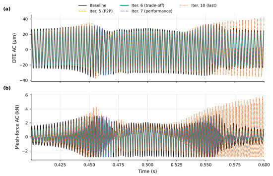
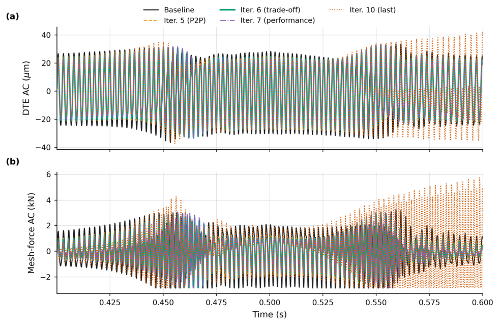
Figure 5 and Table 1 compare the same-initial-condition baseline with the trade-off representative iteration. RMS decreases from 19.39 μm to 17.16 μm, corresponding to an 11.52% reduction. decreases from 1.433 kN to 1.077 kN, corresponding to a 24.85% reduction. The contact loss rate decreases from 3.35% to 0.55%, and the number of re-engagement events decreases from 29 to 5. These results indicate that, under the nominal condition, the learned equivalent line-of-action force compensation reduces both the continuous vibration metrics and the selected contact-switching metrics.
Figure 5.
Mid-window overlays of DTE AC and mesh-force AC responses.: (a) DTE AC response; (b) mesh-force AC response.
Table 1.
Nominal same-initial-condition baseline and trade-off CF-ILC result. DTE, dynamic transmission error; CF-ILC, constrained-force iterative learning compensation.
The RMS reduction is greater than the corresponding peak-to-peak reduction because isolated re-engagement spikes can persist even after the typical fluctuation level has fallen. The response is therefore evaluated using AC RMS and peak-to-peak values together with the contact-loss rate and re-engagement count. Although the 11.52% reduction in DTE AC RMS is moderate, its engineering relevance should be interpreted together with the 24.85% reduction in mesh-force AC RMS and the contact-event measures. The decrease in contact-loss rate from 3.35% to 0.55% corresponds to a 2.80-percentage-point, or 83.6% relative, reduction, while the decrease from 29 to 5 re-engagements represents 82.8% fewer events. These changes indicate a more continuous local load-transfer process, with reduced dynamic tooth-load fluctuation and fewer repeated separation re-engagement events, rather than a uniformly large decrease in every displacement-based metric.
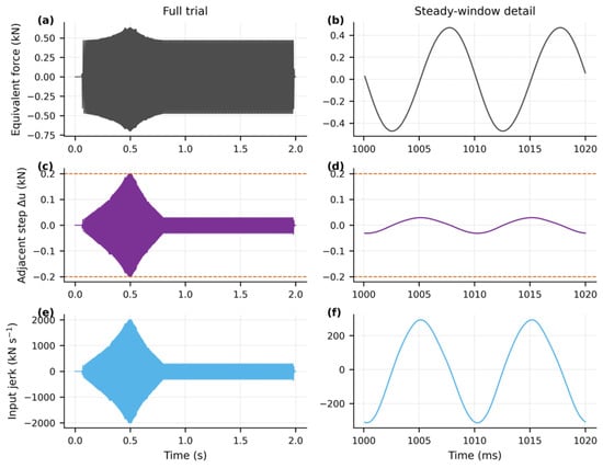
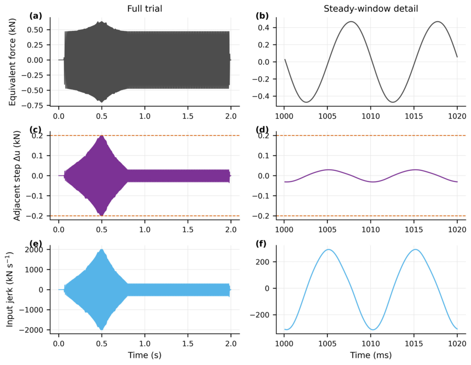
The trade-off input satisfies the imposed numerical bounds: its peak equivalent force is approximately 0.70 kN, and its adjacent-sample increment is limited to ±0.20 kN. No dominant high-frequency jerk spike is evident for the selected trial in Figure 6.
Figure 6.
Input characteristics of the CF-ILC iteration: (a) equivalent line-of-action force over the full trial; (b) steady-window detail of the equivalent force; (c) adjacent-sample command increment over the full trial; (d) steady-window detail of the adjacent-sample increment; (e) input jerk over the full trial; (f) steady-window detail of the input jerk.
3.4. Gear-Contact and Control-Component Ablations
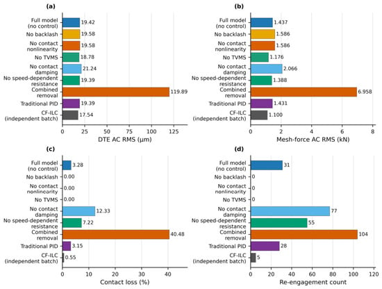
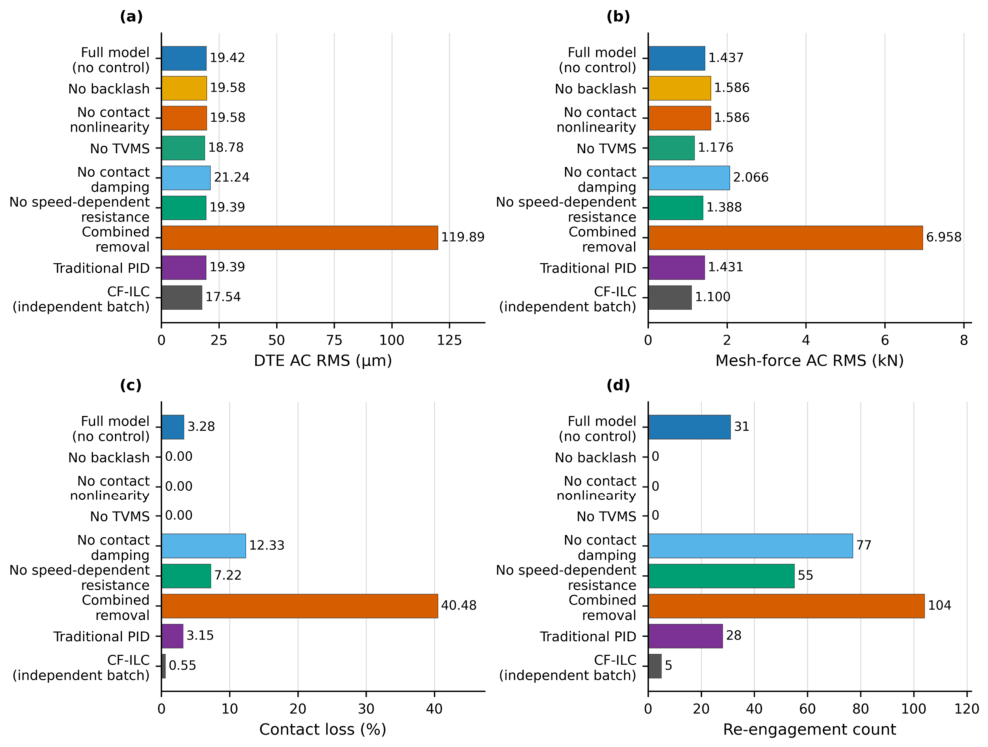
Figure 7 and Table 2 present numerical probes of the underlying mechanisms. The original combined removal of contact damping and speed-dependent resistance could indicate sensitivity to their simultaneous absence, but it could not distinguish their individual effects. Two additional nominal, uncontrolled, same-initial-condition cases were therefore evaluated over the same 0.40–0.60 s window: one with only the contact damping removed and one with only the speed-dependent resistance terms in Equation (3) removed. The full-model baseline and the combined-removal case were rerun in the same batch.
Figure 7.
Numerical ablation of gear-contact and control components: (a) DTE AC RMS; (b) mesh-force AC RMS; (c) contact-loss rate; (d) re-engagement count.
Table 2.
Independent-batch mechanism-oriented ablation and comparator metrics. DTE, dynamic transmission error.
The four dissipation-related cases were evaluated in the same nominal, uncontrolled batch. Removing contact damping alone increased DTE AC RMS from 19.42 to 21.24 μm and mesh-force AC RMS from 1.437 to 2.066 kN; contact loss increased from 3.28% to 12.33%, and re-engagements increased from 31 to 77. Removing the speed-dependent resistance terms changed the two RMS measures only slightly, to 19.39 μm and 1.388 kN, but increased contact loss to 7.22% and re-engagements to 55. When both factors were removed, the corresponding values reached 119.89 μm, 6.958 kN, 40.48%, and 104. Under the present nominal setting, removing contact damping produced the larger changes in the two RMS measures, whereas removing the speed-dependent resistance terms mainly changed the contact-event indicators. Neither single-factor case reproduced the severe combined response.
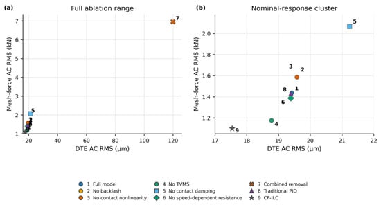
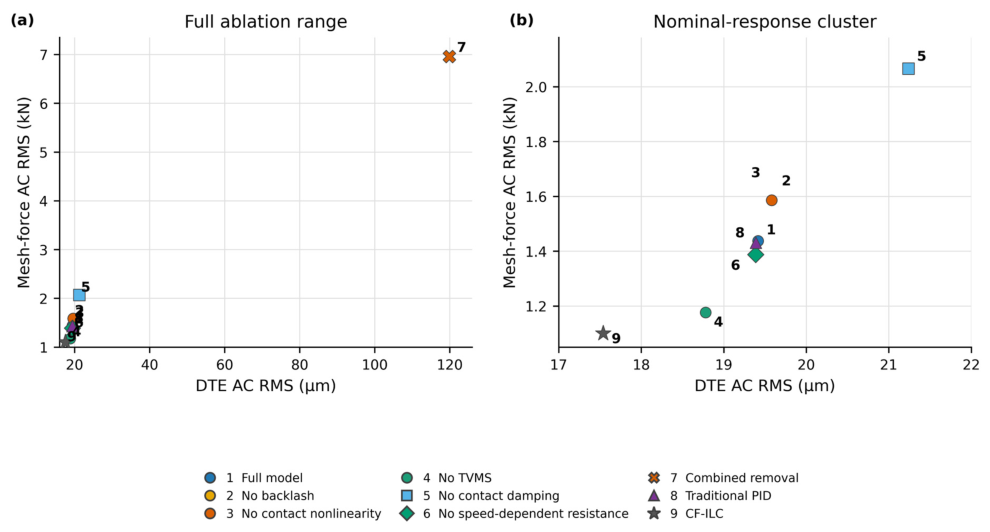
Figure 8 places the ablation cases in the DTE–mesh-force metric plane. The no-speed-dependent-resistance case remains close to the full-model point in the RMS plane, whereas the no-contact-damping case shifts to higher DTE and mesh-force RMS. The combined-removal case lies far outside this nominal-response cluster. Removing TVMS lowers mesh-force AC RMS to 1.176 kN and removes re-engagements in this batch, showing that the selected stiffness modulation contributes materially to the nominal force fluctuation. The no-backlash and no-contact-nonlinearity cases produce the same recorded DTE and mesh-force measures (19.58 μm and 1.586 kN, with no contact events), whereas CF-ILC retains the full model and reduces both continuous and event-based measures.
Figure 8.
DTE–mesh-force metric map for the ablation cases: (a) full ablation range; (b) enlarged view of the nominal-response cluster.
3.5. Actuation-Channel Comparison Under the Nominal Condition
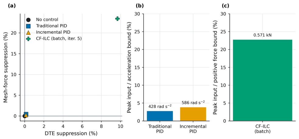
No control, conventional PID, incremental PID and CF-ILC are compared using the same contact model, initial state, prescribed speed task and mid-window metrics.
In contrast, iteration-6 CF-ILC reduces DTE AC RMS from 19.39 to 17.16 μm and mesh-force AC RMS from 1.433 to 1.077 kN; the reductions from unrounded outputs are 11.52% and 24.85%. This result supports closer alignment between the line-of-action input and the selected contact-vibration objectives.
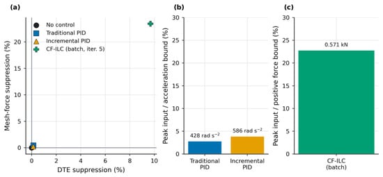
Figure 9 presents suppression together with the corresponding input-cost coordinates. CF-ILC lies in the positive-suppression region for both local metrics, whereas the two other controllers remain closer to zero suppression.
Figure 9.
Suppression–input-cost comparison under the nominal condition: (a) mesh-force suppression versus DTE suppression for no control, traditional PID, incremental PID, and CF-ILC; (b) peak commanded acceleration relative to its prescribed bound for the traditional and incremental PID controllers; (c) peak equivalent line-of-action force relative to its positive force bound for CF-ILC.
To assess learning robustness over repeated operation, a matched same-channel comparison was conducted using an input-constrained ILC without rollback. After completion of the prescribed learning budget, the no-rollback controller had propagated candidates that violated the monitored contact-loss, re-engagement, and mesh-force-peak limits and retained a deteriorated terminal state, with a DTE AC RMS of 18.600 μm, a mesh-force AC RMS of 1.885 kN, a contact-loss rate of 11.144%, and 56 re-engagements. In contrast, CF-ILC rejected the violating candidates and preserved an accepted learning state with corresponding values of 16.812 μm, 1.211 kN, 1.599%, and 16. Relative to the no-rollback comparator, CF-ILC reduced the terminal DTE AC RMS by 9.61%, the mesh-force AC RMS by 35.76%, the contact-loss rate by 85.65%, and the number of re-engagements by 71.43%. These results show that the contact-event-aware acceptance and rollback mechanism prevents deteriorating candidates from being propagated through subsequent learning updates and maintains a more favorable retained state under the present matched variable-speed comparison.
3.6. Paired Numerical Evaluation Under Parameter Perturbations
The 100-case perturbation batch was constructed as a paired numerical stress-test envelope around the nominal model. Positive physical and control parameter groups were scaled using . The DTE-feedback noise amplitude was sampled separately from a half-normal distribution. For each case, the same sampled plant and task parameters were used in the uncontrolled and CF-ILC runs, so that the suppression measures were not confounded by between-case differences in baseline response.
The mean mesh stiffness and stiffness-modulation amplitude shared one factor, the high and low speed levels shared one factor, and the linear and quadratic speed-dependent-resistance coefficients shared one factor. These couplings retained the normalized TVMS shape, the relative structure of the three-stage speed task, and the composition of the lumped resistance terms, respectively. The perturbation scales were selected to provide controlled variation around the nominal model, with wider spreads assigned to lumped damping, load, and resistance terms that are less directly identified.
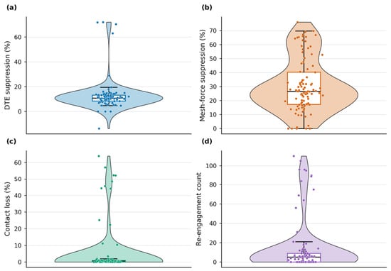
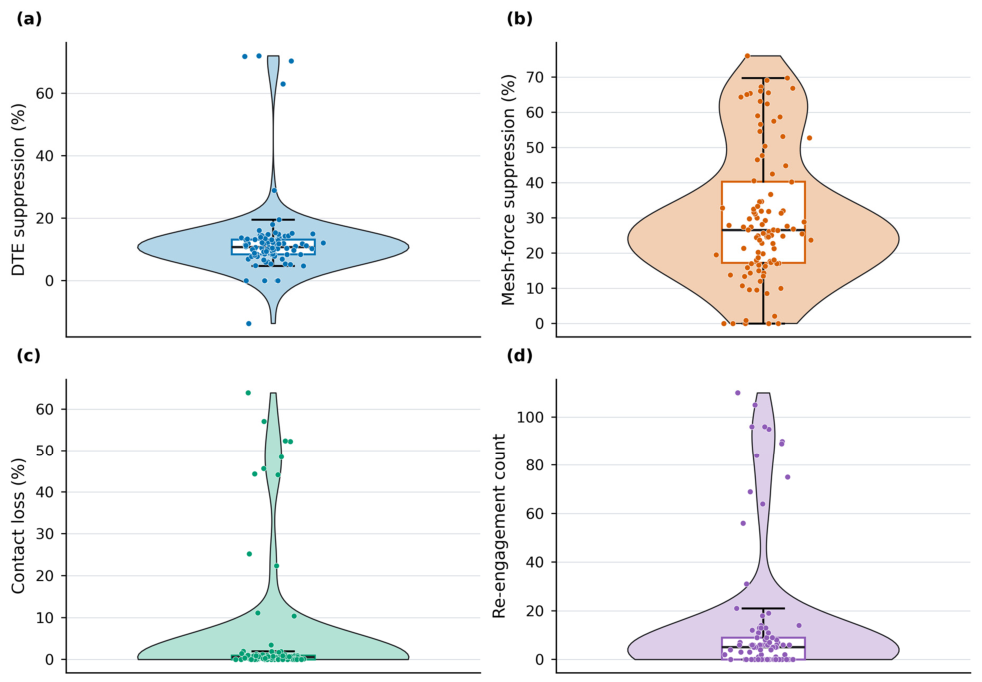
Figure 10 shows the statistical distributions of DTE suppression rate, mesh-force suppression rate, contact loss rate, and re-engagement events for the 100 perturbation samples. Within the tested perturbation range, the two continuous vibration metrics, DTE and mesh force, both exhibit relatively stable positive suppression trends. The mean DTE suppression rate is 12.64%, the median is 10.71%, and the interquartile range is 8.49–13.17%. The mean mesh-force suppression rate is 30.45%, the median is 26.51%, and the interquartile range is 17.26–40.31%. Compared with the nominal condition, the mesh-force suppression in the perturbation statistics remains clearly higher than the DTE suppression, indicating that CF-ILC attenuates mesh-force fluctuation more sufficiently. The DTE response is directly affected by the clearance boundary, transmission error, and re-engagement spikes, and its suppression amplitude is therefore more conservative.
Figure 10.
Distributions across 100 parameter perturbations: (a) DTE suppression; (b) mesh-force suppression; (c) contact-loss rate; (d) re-engagement count.
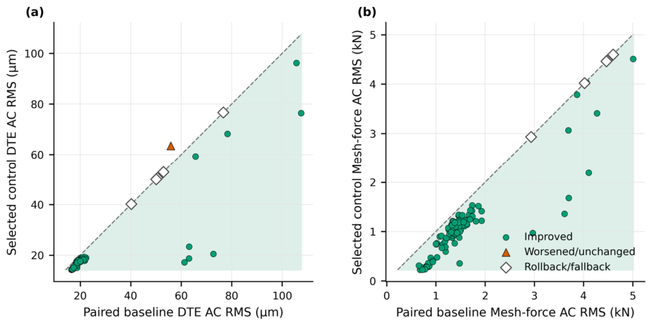
Among the 100 samples, 94 cases achieve positive suppression of both DTE fluctuation and mesh-force fluctuation; 99 cases have nonnegative DTE suppression; and all 100 cases have nonnegative mesh-force suppression. This indicates that, within the current perturbation range, the learning compensation provides highly consistent improvement in the mesh-force channel, while the DTE channel degrades only in a small number of strongly nonsmooth samples. The median contact loss rate is 0.55%, and the median number of re-engagement events is 5, indicating that in most perturbation samples, CF-ILC not only reduces continuous vibration amplitude but also suppresses frequent contact-state switching.
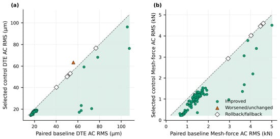
Figure 11 further presents the relationship between the baseline and the selected CF-ILC result from a paired-comparison perspective. For DTE AC RMS and mesh-force AC RMS, a controlled sample located below its baseline sample indicates improvement under that perturbation condition. Most samples fall in the improvement region, showing that CF-ILC is not effective only for a single nominal parameter point, but can maintain local vibration-suppression capability after changes in backlash, stiffness, damping, load, and speed level. In particular, for the mesh-force metric, the controlled results show a more pronounced downward shift relative to the baseline.
Figure 11.
Paired same-perturbation comparison of uncontrolled and selected CF-ILC results: (a) DTE AC RMS; (b) mesh-force AC RMS.
Figure 12 shows the frequency distribution of selected representative iterations in the perturbation batch simulation. Iteration 5 is selected 30 times, iteration 7 is selected 21 times, iteration 6 is selected 15 times, and iteration 4 is selected 13 times; the remaining iterations are selected less frequently. This distribution indicates that, after parameter variation, the most suitable learning iteration is not fixed. Some samples achieve good DTE and mesh-force suppression in earlier iterations, and continued iteration may instead increase high-frequency input or induce rebound in local metrics. Other samples require more iterations to form effective compensation. Therefore, the trade-off representative-selection rule used in this study is not merely a post-processing reporting method, but an important component when CF-ILC is applied to nonsmooth contact systems. By selecting between performance improvement and input quality, it allows different perturbation samples to remain at relatively suitable learning stages.
Figure 12.
Selected-iteration frequencies in the parameter-perturbation batch.
At the candidate level, the event-aware rollback audit identified 194 unsafe candidates across the 100 perturbation cases, and none of these candidates was retained as the next accepted state. In the matched rollback-disabled audit, 252 unsafe candidates were recorded as executed. At the case level, five of the 100 perturbation cases finally fell back to their paired baselines, whereas the remaining 95 retained a learned input.
Overall, the paired batch shows a predominantly positive trend across the sampled parameter range, with mesh-force improvement more consistent than DTE improvement. The observed rollback cases and the single negative-DTE case indicate that DTE improvement can become less consistent when contact loss or re-engagement is stronger.
From an implementation perspective, the current CF-ILC update is performed between repeated trials and consists mainly of filtering, windowing, constraint projection, and the acceptance rollback check; therefore, no online full-horizon optimization is required during a trial. For a larger transmission system, the computational burden will increase mainly with the stored record length and the number of controlled mesh channels. Weakly coupled meshes could be assigned parallel phase-consistent learning channels, whereas strongly coupled stages would require a coordinated multivariable update and a joint acceptance criterion. Practical implementation would further require mesh-specific phase and DTE estimation, mapping of the learned line-of-action forces to the available motor or auxiliary-actuator torques, and incorporation of actuator bandwidth, saturation, rate, and delay limits. These requirements define the next step from the present single-mesh numerical study toward multistage experimental or hardware-in-the-loop validation.
4. Conclusions
This study addresses local nonsmooth contact vibration in a single-stage gear-contact subsystem under repetitive variable-speed operation. The contribution does not lie in phase-dependent TVMS or input-constrained ILC considered separately, but in their control-oriented integration for nonsmooth gear contact. The hybrid-coordinate model separates the prescribed mean-speed task from the local line-of-action dynamics, uses the local relative displacement to correct the reconstructed TVMS phase while retaining a distinct mean-coordinate phase for TE, and introduces compensation only through the local force-balance channel. The learning method combines finite-support candidate shaping and amplitude rate constraints with a trial-level contact-response acceptance and rollback rule, so an input-feasible candidate is not retained when its executed contact response exceeds the prescribed limits.
Because the formulation is based on local mesh phase, DTE feedback, and an equivalent line-of-action input rather than on vehicle-specific states, the same structure may in principle be adapted to other repeatable geared drives, including robotic and machine-tool systems, after system-specific parameter identification and actuator mapping.
For the nominal same-initial-condition comparison, trade-off iteration 6 reduces DTE AC RMS from 19.39 to 17.16 μm and mesh-force AC RMS from 1.433 to 1.077 kN; the reductions from unrounded outputs are 11.52% and 24.85%. Contact loss falls from 3.35% to 0.55%, re-engagements from 29 to 5, and the peak equivalent force is approximately 0.70 kN. Of 100 paired perturbations, 94 improve both RMS measures; median reductions are 10.71% for DTE and 26.51% for mesh force.
These results indicate a predominantly positive performance trend within the tested perturbation range. The present numerical study assumes a repeatable prescribed task and an equivalent line-of-action input. Future work will map this input to motor-torque or auxiliary-actuator commands and assess actuator bandwidth, saturation, sampling delay, and noise on a unified motor–transmission–gear experimental or hardware-in-the-loop platform.
Author Contributions
Conceptualization, M.Z.; methodology, M.Z.; software, M.Z.; validation, M.Z.; formal analysis, M.Z.; investigation, M.Z.; data curation, M.Z.; writing—original draft preparation, M.Z.; writing—review and editing, M.Z.; visualization, M.Z.; supervision, A.S. All authors have read and agreed to the published version of the manuscript.
Funding
This research received no external funding.
Data Availability Statement
The raw data supporting the conclusions of this article will be made available by the authors on request.
Conflicts of Interest
The authors declare no conflicts of interest.
Abbreviations
| Roman Symbols | ||
| Symbol | Definition | Unit |
| Ai | Amplitude of the ith time-varying mesh-stiffness harmonic | N m−1 |
| acmd(t) | Prescribed mean-coordinate angular acceleration | rad s−2 |
| bhalf | Half-backlash width | m |
| Ca | Quadratic speed-dependent resistance coefficient in the reduced-order load model | N s2 rad−2 |
| Cu,j | Normalized input-quality cost for trial j | – |
| Cv | Linear speed-dependent resistance coefficient in the reduced-order load model | N s rad−1 |
| ceff | Contact-state-dependent effective damping coefficient | N s m−1 |
| cm | Normal contact-damping coefficient during engagement | N s m−1 |
| csep | Separated-state damping coefficient | N s m−1 |
| e(t) | Transmission-error displacement excitation | m |
| ea | Transmission-error amplitude | m |
| Fc(t) | Active equivalent compensation force along the line of action | N |
| Fdist(t) | Optional external disturbance force | N |
| Fload(t) | Equivalent line-of-action load | N |
| Fmesh(t) | Signed mesh force | N |
| Fn(t) | Non-negative normal contact force | N |
| Fstatic | Static preload | N |
| fb(xgap) | Signed backlash dead-zone output | m |
| fc | Cut-off frequency of the symmetric FFT low-pass operator | Hz |
| Gyu | Conversion gain from DTE feedback to force command | kN μm−1 |
| Ic | Contact-state indicator | – |
| IM,j | Improvement rate of metric M at trial j | % |
| Jg,Jp | Rotational inertias of the gear and pinion | kg m2 |
| Jjerk,j | Normalized jerk measure for trial j | – |
| Jmid,j | Mid-window residual score for trial j | – |
| km | Mean mesh stiffness | N m−1 |
| kmin | Positivity floor of the reconstructed time-varying mesh stiffness | N m−1 |
| kraw(φk) | Unclipped phase-domain mesh stiffness | N m−1 |
| kt(φk) | Bounded time-varying mesh stiffness | N m−1 |
| m | Gear module | m |
| meq | Equivalent mass projected onto the line of action | kg |
| M,M0,Mj | Generic performance metric and its baseline and trial-j values | Metric-dependent |
| ni | Harmonic order of the ith stiffness term | – |
| Nh | Number of time-varying mesh-stiffness harmonics | – |
| qf | Scalar retention/forgetting factor | – |
| rg,rp | Base-circle radii of the gear and pinion | m |
| s(k) | Generic sampled signal used in the performance metrics | Signal-dependent |
| sc | Sign of the active contact flank | – |
| SP2P,j | Composite peak-to-peak improvement score for trial j | % |
| SRMS,j | Composite RMS improvement score for trial j | % |
| t,t1,t2 | Time and switching times of the prescribed speed task | s |
| uj(k) | Retained force-command sequence used for the trial-to-trial update | kN |
| Constrained stored candidate before trial-level acceptance or rollback | kN | |
| Force-command sequence actually applied to the plant | kN | |
| uHF,rms,j | Normalized high-frequency input RMS for trial j | – |
| umin,umax | Lower and upper amplitude limits of the force command | kN |
| vrel(t) | Relative line-of-action velocity | m s−1 |
| w(k) | Raised-cosine application and learning window | – |
| x(t) | Hybrid-coordinate state vector | Mixed |
| xbias | Preload-equilibrium displacement used to construct DTE feedback | m |
| xgap(t) | Effective clearance coordinate | m |
| xrel(t) | Relative line-of-action displacement used as the DTE coordinate | m |
| yj(k) | DTE-derived feedback sequence for trial j | μm |
| Zg,Zp | Numbers of gear and pinion teeth | – |
| Greek Symbols | ||
| Symbol | Definition | Unit |
| α0 | Pressure angle | rad |
| γj | Learning gain at trial j | – |
| δ | Non-negative contact compression | m |
| Contact-compression rate | m s−1 | |
| Δumax | Maximum adjacent-sample command increment | kN |
| ε | Small positive regularization constant | – |
| θavg | Mean angular displacement | rad |
| θphase | Reconstructed angular coordinate used for TVMS | rad |
| θp | Reconstructed pinion phase coordinate | rad |
| φe | Mechanical phase of the transmission-error excitation | rad |
| φk | Mechanical phase of the time-varying mesh stiffness | rad |
| ψi | Phase offset of the ith stiffness harmonic | rad |
| ωavg | Mean angular velocity | rad s−1 |
| ωh,ωl | Prescribed high- and low-speed levels | rad s−1 |
| Abbreviations | ||
| Abbreviation | Definition | |
| AC | Alternating component | |
| CF-ILC | Constrained-force iterative learning compensation | |
| DC | Direct-current or mean component | |
| DTE | Dynamic transmission error | |
| FFT | Fast Fourier transform | |
| HF | High frequency | |
| ILC | Iterative learning control | |
| P2P | Peak-to-peak | |
| PID | Proportional-integral-derivative | |
| RMS | Root mean square | |
| TE | Transmission error | |
| TVMS | Time-varying mesh stiffness | |
References
- Guan, Y.H.; Lim, T.C.; Shepard, W.S., Jr. Experimental study on active vibration control of a gearbox system. J. Sound Vib. 2005, 282, 713–733. [Google Scholar] [CrossRef] [Scilit]
- Hotait, M.A.; Kahraman, A. Experiments on the relationship between the dynamic transmission error and the dynamic stress factor of spur gear pairs. Mech. Mach. Theory 2013, 70, 116–128. [Google Scholar] [CrossRef] [Scilit]
- Özgüven, H.N.; Houser, D.R. Mathematical models used in gear dynamics—A review. J. Sound Vib. 1988, 121, 383–411. [Google Scholar] [CrossRef] [Scilit]
- Blankenship, G.W.; Singh, R. A new gear mesh interface dynamic model to predict multi-dimensional force coupling and excitation. Mech. Mach. Theory 1995, 30, 43–57. [Google Scholar] [CrossRef] [Scilit]
- Kahraman, A.; Singh, R. Non-linear dynamics of a spur gear pair. J. Sound Vib. 1990, 142, 49–75. [Google Scholar] [CrossRef] [Scilit]
- Kahraman, A.; Singh, R. Interactions between time-varying mesh stiffness and clearance non-linearities in a geared system. J. Sound Vib. 1991, 146, 135–156. [Google Scholar] [CrossRef] [Scilit]
- Khabou, M.T.; Bouchaala, N.; Chaari, F.; Fakhfakh, T.; Haddar, M. Study of a spur gear dynamic behavior in transient regime. Mech. Syst. Signal Process. 2011, 25, 3089–3101. [Google Scholar] [CrossRef] [Scilit]
- Velex, P.; Ajmi, M. On the modelling of excitations in geared systems by transmission errors. J. Sound Vib. 2006, 290, 882–909. [Google Scholar] [CrossRef] [Scilit]
- Walha, L.; Fakhfakh, T.; Haddar, M. Nonlinear dynamics of a two-stage gear system with mesh stiffness fluctuation, bearing flexibility and backlash. Mech. Mach. Theory 2009, 44, 1058–1069. [Google Scholar] [CrossRef] [Scilit]
- Ma, H.; Zeng, J.; Feng, R.; Pang, X.; Wen, B. An improved analytical method for mesh stiffness calculation of spur gears with tip relief. Mech. Mach. Theory 2016, 98, 64–80. [Google Scholar] [CrossRef] [Scilit]
- Marafona, J.D.M.; Marques, P.M.T.; Martins, R.C.; Seabra, J.H.O. Mesh stiffness models for cylindrical gears: A detailed review. Mech. Mach. Theory 2021, 166, 104472. [Google Scholar] [CrossRef] [Scilit]
- Fernández del Rincón, A.; Viadero, F.; Iglesias, M.; García, P.; de-Juan, A.; Sancibrian, R. A model for the study of meshing stiffness in spur gear transmissions. Mech. Mach. Theory 2013, 61, 30–58. [Google Scholar] [CrossRef] [Scilit]
- Machado, M.; Moreira, P.; Flores, P.; Lankarani, H.M. Compliant contact force models in multibody dynamics: Evolution of the Hertz contact theory. Mech. Mach. Theory 2012, 53, 99–121. [Google Scholar] [CrossRef] [Scilit]
- Parker, R.G.; Vijayakar, S.M.; Imajo, T. Non-linear dynamic response of a spur gear pair: Modelling and experimental comparisons. J. Sound Vib. 2000, 237, 435–455. [Google Scholar] [CrossRef] [Scilit]
- Åström, K.J.; Hägglund, T. Advanced PID Control; ISA—The Instrumentation, Systems, and Automation Society: Research Triangle Park, NC, USA, 2006. [Google Scholar]
- Dogruer, C.U.; Pirsoltan, A.K. Active vibration control of a single-stage spur gearbox. Mech. Syst. Signal Process. 2017, 85, 429–444. [Google Scholar] [CrossRef] [Scilit]
- Arimoto, S.; Kawamura, S.; Miyazaki, F. Bettering operation of robots by learning. J. Robot. Syst. 1984, 1, 123–140. [Google Scholar] [CrossRef] [Scilit]
- Bristow, D.A.; Tharayil, M.; Alleyne, A.G. A survey of iterative learning control: A learning-based method for high-performance tracking control. IEEE Control Syst. Mag. 2006, 26, 96–114. [Google Scholar] [CrossRef] [Scilit]
- Wang, C.; Zheng, M.; Wang, Z.; Peng, C.; Tomizuka, M. Robust iterative learning control for vibration suppression of industrial robot manipulators. J. Dyn. Syst. Meas. Control 2018, 140, 011003. [Google Scholar] [CrossRef] [Scilit]
- Chi, R.; Liu, X.; Zhang, R.; Hou, Z.; Huang, B. Constrained data-driven optimal iterative learning control. J. Process Control 2017, 55, 10–29. [Google Scholar] [CrossRef] [Scilit]
- He, W.; Meng, T.; He, X.; Ge, S.S. Unified iterative learning control for flexible structures with input constraints. Automatica 2018, 96, 326–336. [Google Scholar] [CrossRef] [Scilit]
- Ge, S.; Qiu, L.; Zhang, Z.; Wang, H.; Hu, M. Electromechanical coupling dynamic characteristics of electric drive system for electric vehicle. Nonlinear Dyn. 2024, 112, 6101–6136. [Google Scholar] [CrossRef] [Scilit]
- Pei, J.; Tian, Y.; Hou, H.; Tao, Y.; Wu, M.; Guan, Z. Dynamic response and lubrication performance of spur gear pair under time-varying rotation speeds. Lubricants 2025, 13, 15. [Google Scholar] [CrossRef] [Scilit]
- Chen, S.; Hu, M. Active torsional vibration suppression of integrated electric drive system based on optimal harmonic current instruction analytic calculation method. Mech. Mach. Theory 2023, 180, 105136. [Google Scholar] [CrossRef] [Scilit]
- Ge, S.; Hou, S.; Yang, Y.; Zhang, Z.; Tang, F. Active vibration control of electric drive system in electric vehicles based on active disturbance rejection current compensation under impact conditions. SAE Int. J. Veh. Dyn. Stab. NVH 2023, 7, 513–531. [Google Scholar] [CrossRef] [Scilit]
- Sun, Z.; Hu, J.; Xin, Y.; Guo, Q.; Yao, Z.; Yang, Y. Active torsional vibration suppression for integrated electric drive system considering nonlinear factors. Nonlinear Dyn. 2024, 112, 17107–17127. [Google Scholar] [CrossRef] [Scilit]
- Yang, W.; Li, S.; Luo, X. Data driven vibration control: A review. IEEE/CAA J. Autom. Sin. 2024, 11, 1898–1917. [Google Scholar] [CrossRef] [Scilit]



Disclaimer/Publisher’s Note: The statements, opinions and data contained in all publications are solely those of the individual author(s) and contributor(s) and not of MDPI and/or the editor(s). MDPI and/or the editor(s) disclaim responsibility for any injury to people or property resulting from any ideas, methods, instructions or products referred to in the content. |
© 2026 by the authors. Licensee MDPI, Basel, Switzerland. This article is an open access article distributed under the terms and conditions of the Creative Commons Attribution (CC BY) license.