


Abstract
Quantum watermarking is a technique that embeds specific information into a quantum carrier for the purpose of digital copyright protection. In this paper, we propose a novel color image watermarking algorithm that integrates quantum discrete wavelet transform with Sinusoidal–Tent mapping and baker mapping. Initially, chaotic sequences are generated using Sinusoidal–Tent mapping to determine the channels suitable for watermark embedding. Subsequently, a one-level quantum Haar wavelet transform is applied to the selected channel to decompose the image. The watermarked image is then scrambled via discrete baker mapping, and the scrambled image is embedded into the High-High subbands. The invisibility of the watermark is evaluated by calculating the peak signal-to-noise ratio, Structural similarity index measure, and Learned Perceptual Image Patch Similarity, with comparisons made against the color histogram. The robustness of the proposed algorithm is assessed through the calculation of Normalized Cross-Correlation. In the simulation results, PSNR is close to 63, SSIM is close to 1, LPIPS is close to 0.001, and NCC is close to 0.97. This indicates that the proposed watermarking algorithm exhibits excellent visual quality and a robust capability to withstand various attacks. Additionally, through ablation study, the contribution of each technique to overall performance was systematically evaluated.
1. Introduction
Advancements in quantum computing have unlocked new possibilities in quantum image processing, encompassing research into quantum image representation techniques and the development of quantum image processing algorithms [1]. As the foundation of quantum image processing, several prominent quantum image representation methods have been put forward. Venegas-Andraca et al. succeeded in quantum image preparation by combining single quantum bits and created a quantum image representation model based on quantum bit arrays [2]. Le et al. developed the Flexible Representation of Quantum Images (FRQI) model [3], which represents each pixel’s grayscale value through the angular encoding of quantum bits. Building on the FRQI model, Zhang et al. introduced the Novel Enhanced Quantum Representation (NEQR) model [4], which significantly reduces the complexity of corresponding quantum operations. To cater to diverse application scenarios, numerous scholars have designed a range of quantum image representation models based on FRQI and NEQR. These include the Improved NEQR (INEQR) model [5], applicable to images of any size, the New Quantum Color Image (NCQI) model [6], and the Improved FRQI (FRQCI) model [7]. While FRQI and NEQR are quantum image representation models for grayscale images, the growing prevalence of color images in modern applications has spurred the development of models like NCQI and FRQCI, specifically tailored for color images. The NCQI model effectively represents the RGB values of each pixel using quantum ground state sequences, enabling straightforward manipulation. This approach exhibits significant flexibility and holds substantial potential for advancements in color quantum image processing.
The rapid advancement of digital technology has significantly enhanced global communication and the dissemination of information. Concurrently, there has been a marked increase in illegal activities such as piracy, data tampering, and copyright infringement. To address the challenges posed by information security, techniques such as cryptography, steganography, and watermarking are widely employed [8]. Quantum watermarking is a technique that embeds a watermark image into a carrier image to achieve multiple goals, including copyright protection, secure information transmission, and tamper resistance. Thanks to its strong anti-attack capabilities, quantum watermarking can effectively withstand various attacks that commonly affect traditional digital watermarking methods, such as compression and noise attacks. As a key research area at the intersection of quantum computing and image processing, quantum watermarking has attracted widespread attention from academic institutions and researchers, resulting in numerous significant advancements and research findings. In 2013, Song proposed a non-static watermark embedding scheme that utilized quantum wavelet transform techniques. This approach employed dynamic vectors to regulate the embedding intensity rather than relying on a fixed parameter for controlling the embedding process [9]. Similarly, Zhang et al. introduced a robust quantum watermarking strategy based on quantum Fourier transform by integrating the watermarked image into the Fourier coefficients of the quantum carrier image, thereby preserving the visual integrity of the carrier [10]. However, in 2014, Yang et al. pointed out errors associated with directly generalizing classical watermarking algorithms to quantum contexts, as noted in existing literature [11]. In 2015, Yan et al. developed a dual watermarking strategy tailored for multichannel quantum images by leveraging numerous effective transforms involving Region of Interest, along with channel exchange and quantum Fourier transform techniques [12,13]. In 2019, leveraging the strong energy compression characteristic of quantum discrete wavelet transform, Hu et al. proposed a watermarking algorithm based on quantum Haar wavelet transform, which improved the invisibility of the watermarking algorithm [14]. In 2023, Su et al. applied quantum Haar wavelet transform and quantum least significant bit (LSB) blocking technology to carrier grayscale images, embedding scrambled watermark images into quantum wavelet coefficients. This approach better preserved the local details of the images and enhanced their visual quality [15]. In 2024, to enhance visual quality and embedding capabilities, Zeng et al. proposed a quantum watermarking algorithm that combines quantum discrete cosine transform and Tent mapping [16]. In the same year, Li et al. put forward a quantum color image watermarking method that integrates quantum discrete cosine transform technology with quantum LOG edge detection technology, which improves the watermarking algorithm’s ability to resist various attacks [17].
With the continuous progress of research in chaos theory, chaotic systems have been widely applied in the field of image watermarking due to their complex dynamics. To enhance the security of the algorithm, watermarking algorithms typically encrypt and preprocess the original watermark information before performing the watermark embedding operation [18,19]. Chaotic mapping, known for its high sensitivity to initial conditions and characterized by its traversability and orbital unpredictability, effectively meets the requirements for image encryption and has thus been widely adopted [20,21]. Zhou et al. proposed a scheme that uses a hyperchaotic system to control the bit layer cross-exchange operation to achieve quantum color image encryption, and achieved good encryption results [22]. Ran et al. achieved quantum color image encryption by using a coupled hyperchaotic Lorenz system with three-pulse injection. The algorithm features a large key space and low complexity [23]. Lu et al. utilized three chaotic sequences in combination with a controlled revolving door to change the pixel color, achieving position scrambling and gray value scrambling, and obtaining an encrypted image [24]. The simple structure of one-dimensional chaotic mapping makes them suitable for generating chaotic sequences. In this paper, we use one-dimensional chaotic mapping for this purpose. Given the advantages of quantum computing models, quantum image scrambling technology has been developed for quantum watermarking applications. If one-dimensional chaotic mapping is used to scramble the coordinates of pixel points, achieving an optimal scrambling effect requires extensive iterations, leading to increased computational complexity and slower execution speeds. To address these limitations, this paper proposes a more concise and effective algorithm based on two-dimensional chaotic mapping for quantum image discretization. In response to the weaknesses of the latest watermarking algorithms based on quantum discrete cosine transform—namely, their vulnerability to geometric attacks and high computational complexity—this paper integrates quantum Haar wavelet transform with Sinusoidal–Tent mapping and baker mapping to design a novel color image watermarking algorithm. Simulation results and performance analysis confirm the feasibility and effectiveness of the proposed algorithm. The primary contributions of this paper can be summarized as follows:
- 1.
- A color image watermarking algorithm is proposed, which integrates quantum discrete wavelet transform (QDWT) and chaotic mapping. Additionally, a quantum circuit diagram for the decomposition of NCQI images using quantum Haar wavelet transform (QHWT) is presented, along with a detailed process for decomposing NCQI images based on the quantum circuit.
- 2.
- The combination of one-dimensional and two-dimensional chaotic mapping is employed in this study. Specifically, one-dimensional chaotic mapping is utilized to generate chaotic sequences, while two-dimensional chaotic mapping is applied for image scrambling, thereby fully leveraging the advantages of both methods.
- 3.
- In the experiments, Learned Perceptual Image Patch Similarity (LPIPS) detection is introduced to evaluate the differences between images by utilizing features extracted through deep learning models. This approach aligns more closely with human perceptual characteristics compared to traditional metrics such as peak signal-to-noise ratio (PSNR) and Structure Similarity Index Measure (SSIM).
The rest of this paper is organized as follows: Section 1 gives an overview of the research background and significance of quantum image watermarking technology, and briefly introduces the current status of domestic and international research on quantum image watermarking technology. Section 2 describes the basics of quantum image representation, quantum Haar wavelet transform, Sinusoidal–Tent mapping, baker mapping, quantum module and so on. Section 3 proposes a quantum color image watermarking algorithm based on quantum discrete wavelet transform and Sinusoidal–Tent mapping, and baker mapping. Section 4 describes the watermarking judging criteria and attack types, and evaluates and analyzes the performance of the algorithm in various aspects. Finally, Section 5 describes the conclusions and future work of this paper.
2. Preliminaries
2.1. Quantum Image Representation
When processing classical digital images using quantum methods, it is necessary to first convert the digital images into quantum states before proceeding with subsequent quantum operations.
Novel Enhanced Quantum Image Representation (NEQR) integrates the coordinate position and color information of a quantum image into a normalized superposition of quantum states through two entangled sequences of qubits [4]. For a quantum image with dimensions and pixel values in the range , its NEQR representation is defined as follows:
is the binary sequence encoding the pixel value , represents the color information of the image, and represents the position information of the image.
NEQR is a quantum image representation model for grayscale images, therefore, in order to realize the quantum representation of color images, Sang et al. improved the NEQR model and designed the NCQI model [6]. The NCQI model classifies the color information into three channels: R, G, and B. An RGB color image of size can be represented using the NCQI model as follows:
, , and denote the gray values of the pixels in the R-channel, G-channel and B-channel, respectively.
2.2. Quantum Haar Wavelet Transform
After converting the digital image into the representation of a quantum state, quantum operations are described and implemented by applying a series of unitary matrices of size in n-qubit registers. Wavelet transform plays a very important role in image processing [25]. In the quantum field, we will introduce the quantum Haar wavelet transform and its quantum circuits.
Before introducing the effective circuits of the quantum Haar wavelet transform, it is necessary to introduce the Hadamard (H) gate as well as the positive shift substitution matrix .
The Hadamard gate is represented by the following matrix:
The result of acting on the n-quantum bit register is as follows:
Element in is represented as:
For example, when , , .
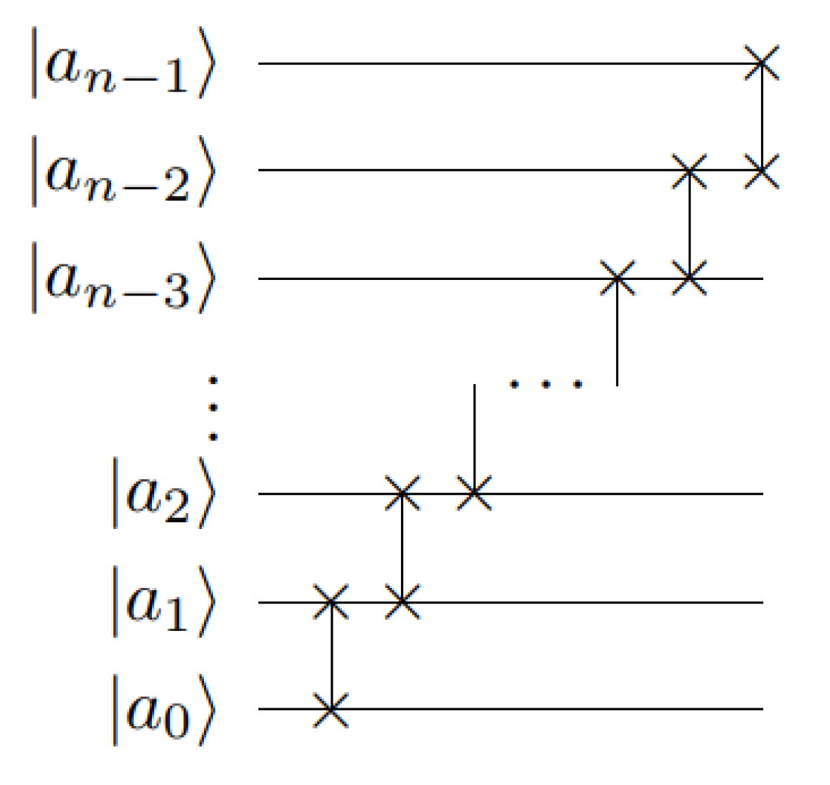
The quantum circuit for is shown in Figure 1:
Figure 1.
Quantum circuit of .
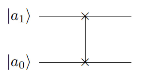
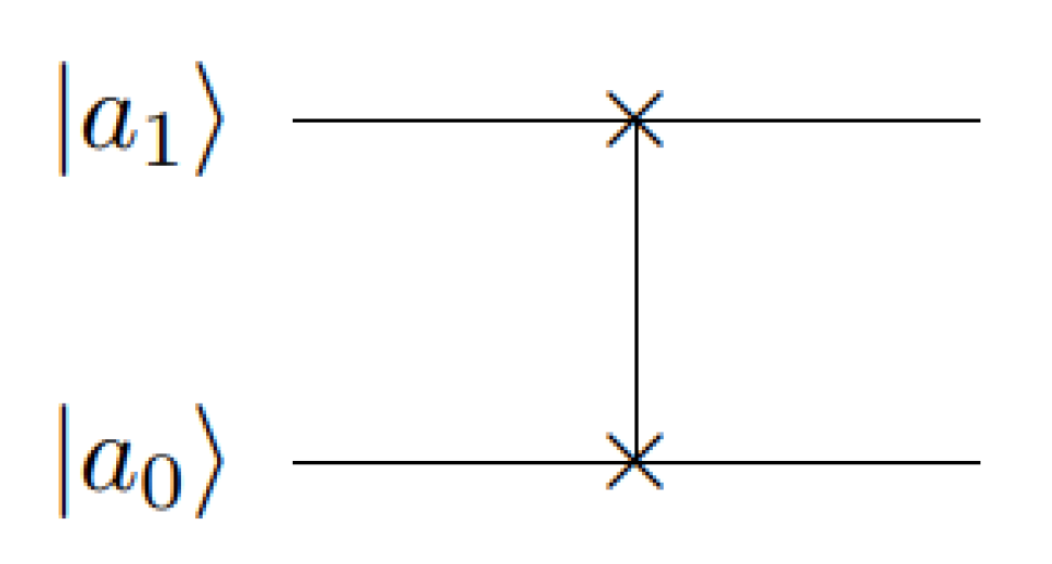
The matrix form of the SWAP gate is , and the corresponding quantum circuit is shown in Figure 2:
Figure 2.
Quantum circuit of SWAP gate.
Thus can be decomposed into:
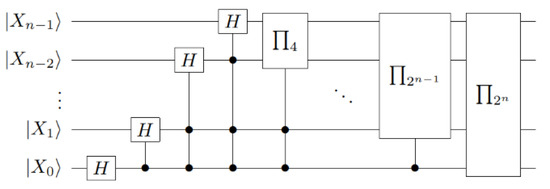
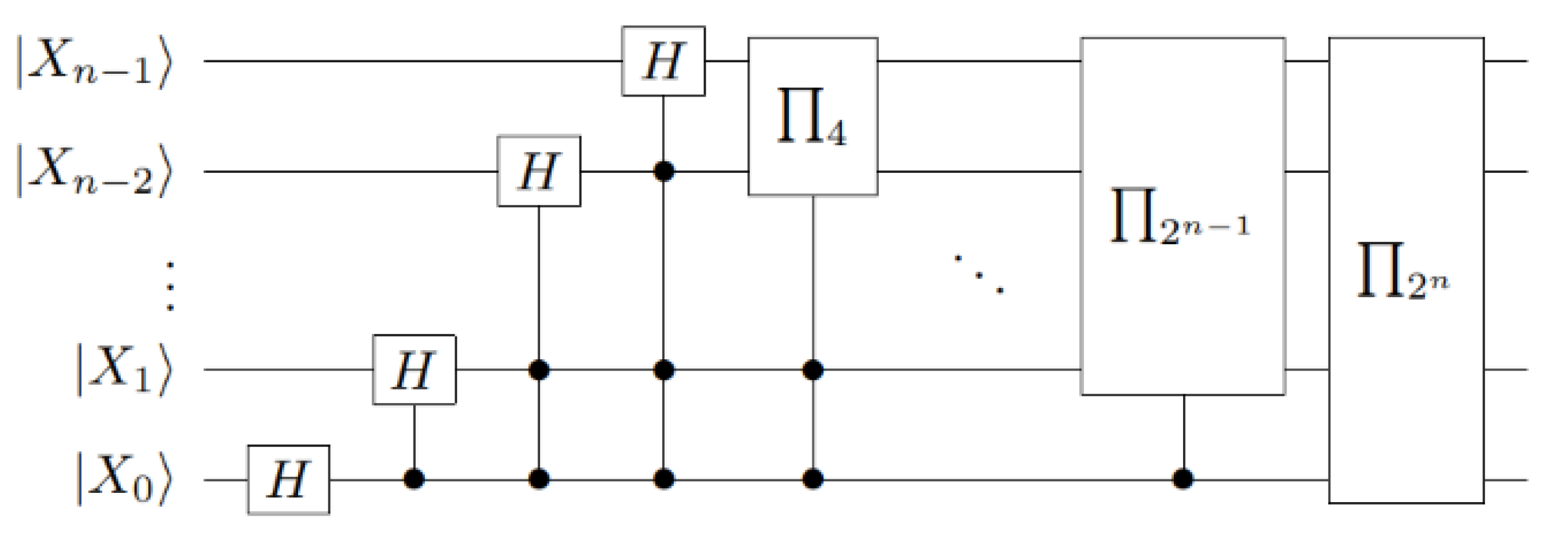
Based on the Hadamard gate and the positive shift substitution matrix , the quantum Haar wavelet transform of the quantum circuit can be obtained, as shown in Figure 3:
Figure 3.
Quantum circuit of the quantum Haar wavelet transform.
Thus, the matrix form of the quantum Haar wavelet transform can be expressed as follows:
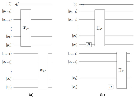
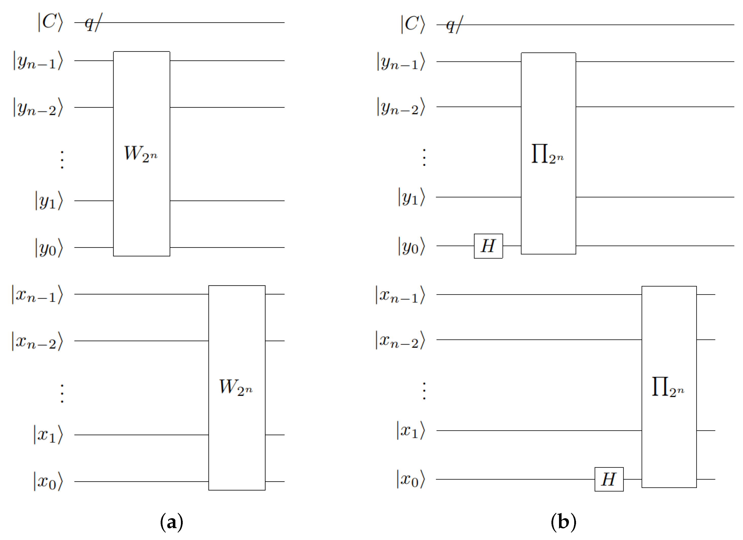
After applying the NCQI model representation to the image, we can use QHWT to decompose the quantum image. Figure 4a shows the quantum circuit of the full-order QHWT decomposition for the rows and columns of image , respectively.
Figure 4.
Quantum circuits of QHWT: (a) quantum circuit of full levels QHWT, (b) quantum circuit of first level QHWT.
The row decomposition of the NCQI image coordinate quantum bit in the horizontal direction is realized using operator . Similarly, the column decomposition is realized in the vertical direction for the coordinate quantum bit . The full-order QHWT matrix form of the NCQI image decomposition is denoted as follows:
For the NCQI model, the watermark embedding can be performed directly in the first-level QHWT image decomposition, and the quantum circuit of the first-level QHWT is shown in Figure 4b.
Thus, the matrix form of the first-level QHWT decomposition of the NCQI image is represented as follows:
2.2.1. Sinusoidal–Tent Mapping
This paper utilizes one-dimensional piecewise chaotic mapping, specifically Sinusoidal–Tent mapping (ST mapping) [16], which is generated by combining Sinusoidal mapping and Tent mapping, as shown in Equation (10):
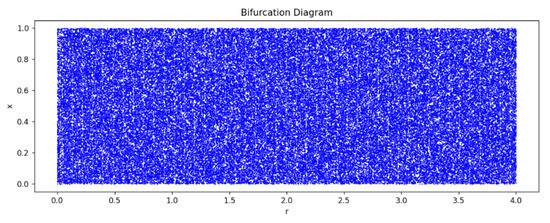
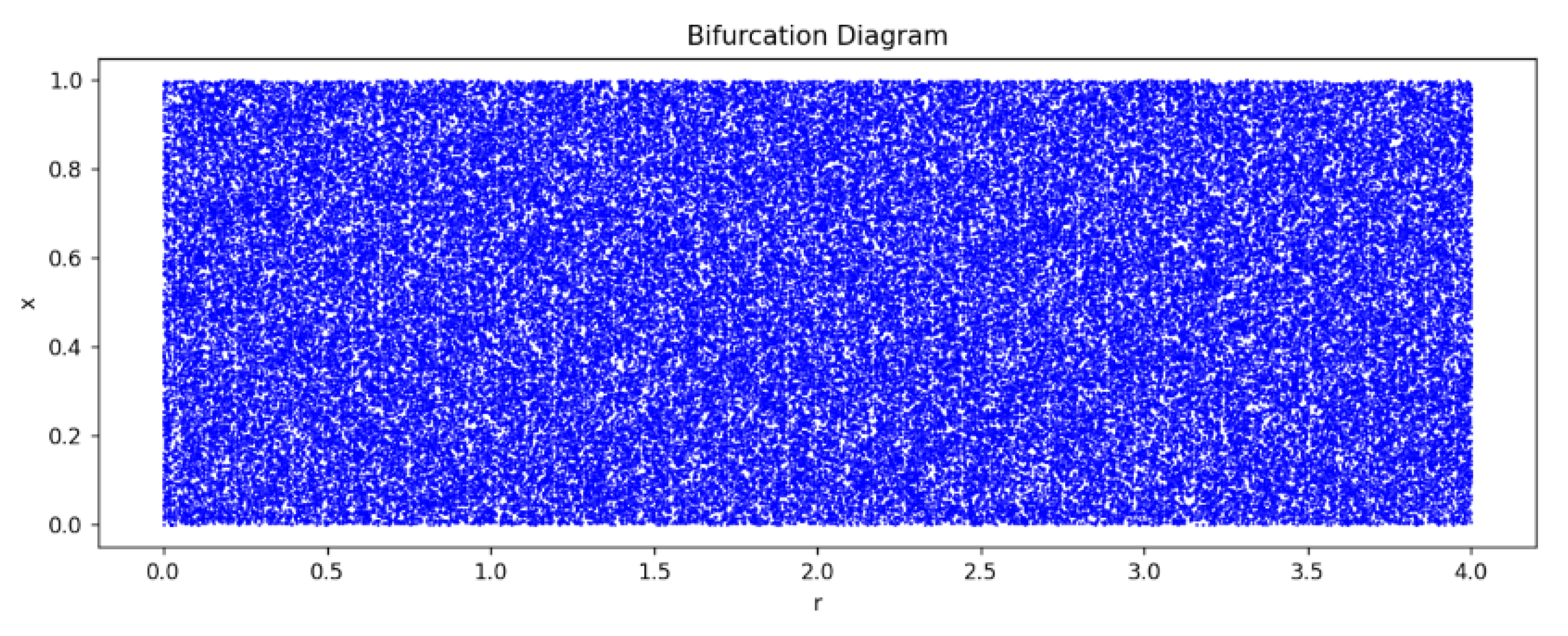
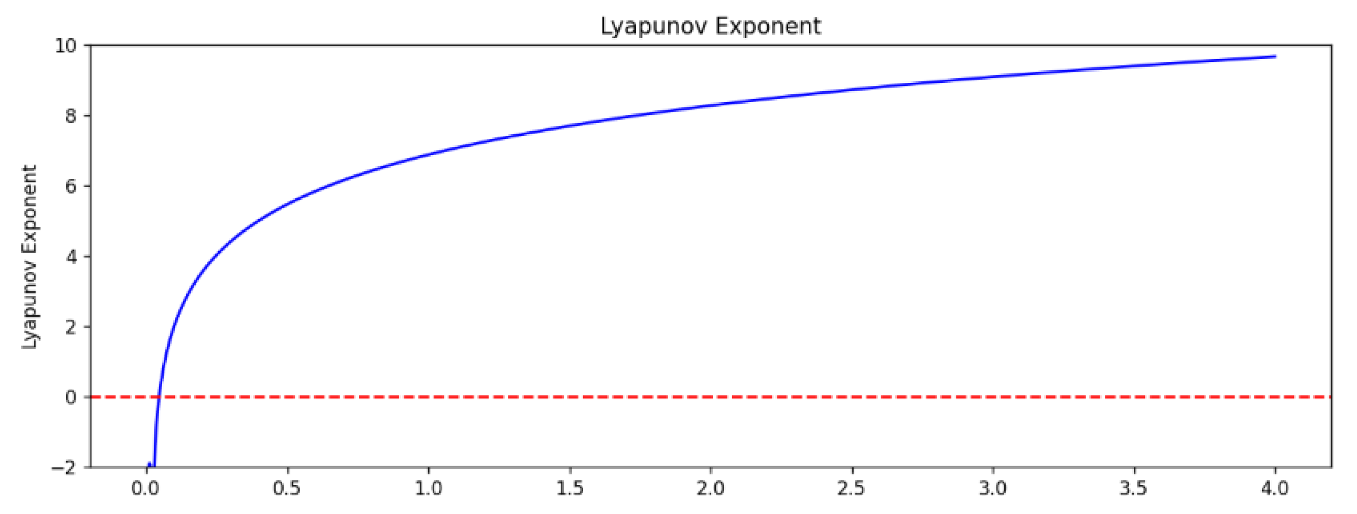
where , are the chaotic sequences output by ST mapping. Bifurcation and Lyapunov exponential plots [26] of ST mapping are shown in Figure 5 and Figure 6, respectively.
Figure 5.
Bifurcation diagram.
Figure 6.
Diagram of Lyapunov’s Index.
As illustrated in Figure 5, the ST mapping is in a chaotic state within the range set by the control parameters and the output sequence is uniformly distributed within , exhibiting complex chaotic behavior. Furthermore, as shown in Figure 6, the Liapunov exponent of the ST mapping remains predominantly positive across the specified control parameter range, indicating robust chaotic characteristics.
2.2.2. Baker Mapping
Baker mapping shows excellent performance in pixel position obfuscation, which can effectively disrupt the arrangement order of pixels and thus improve the security of images [27]. The classical baker mapping expression is:
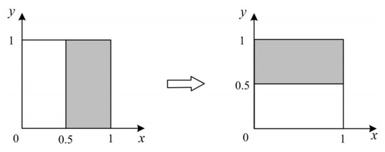
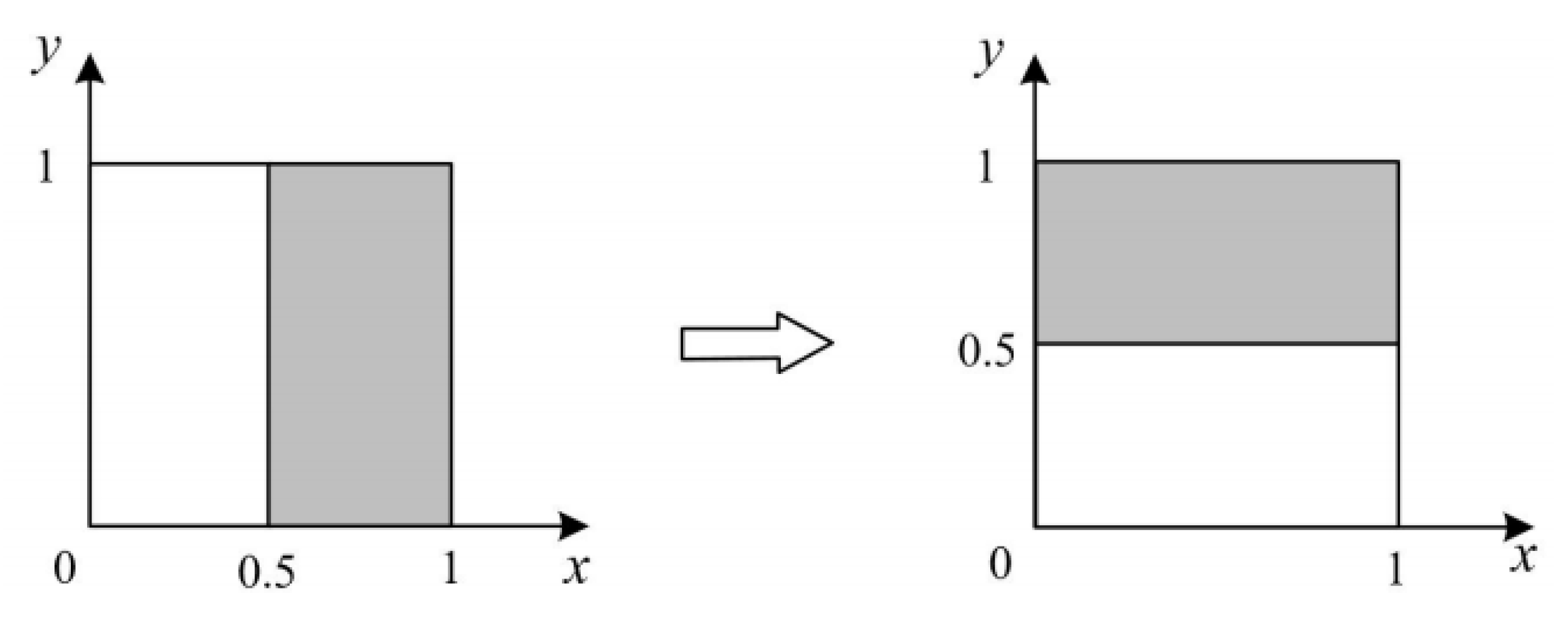
As shown in Figure 7, the classical baker mapping splits the square image into left and right sub-blocks, which are subsequently mapped into new upper and lower sub-blocks, respectively, by a specific map rule.
Figure 7.
Classic Baker mapping.
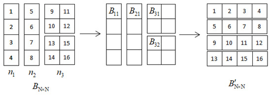
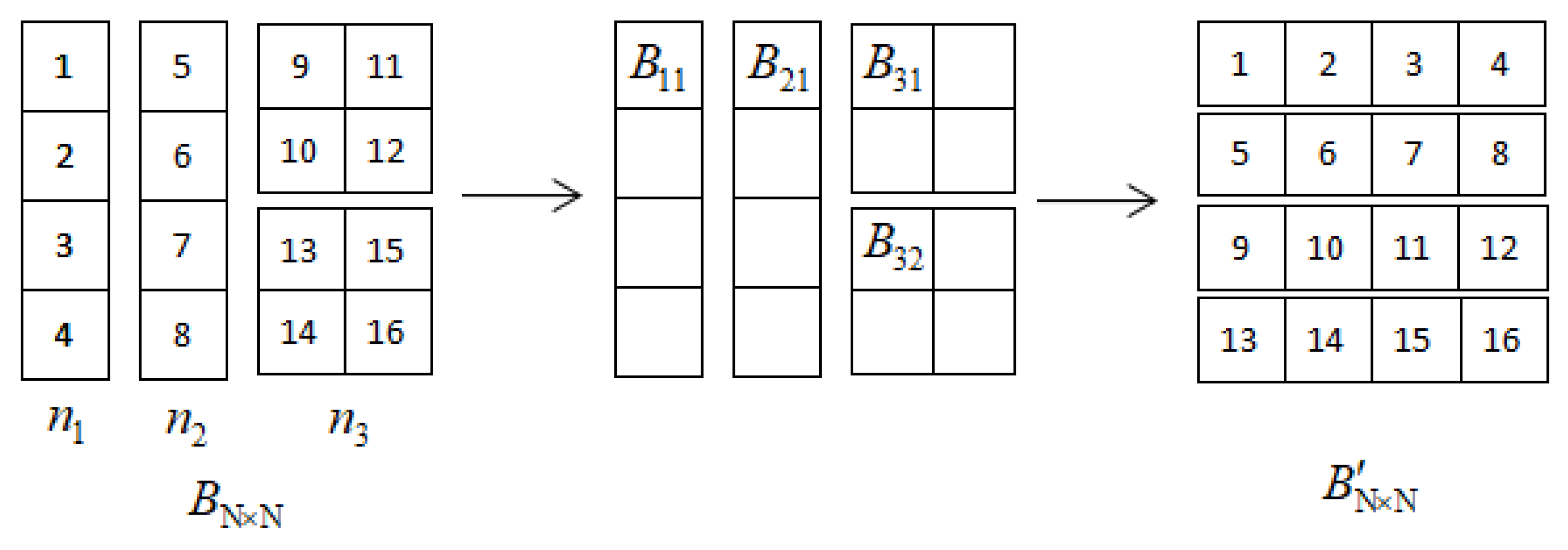
In order to effectively apply baker mapping in images, it needs to be discretized. The discretized baker mapping can more accurately adapt to the characteristics of the image data, thus ensuring the feasibility of the map operation. Let be the transformation parameter, , , and is divisible by N, , . For each pixel in the original image , the discrete baker mapping can be expressed as Equation (12). For example, when N = 4, = = 1, = 2, the discrete baker mapping is shown in Figure 8.
Figure 8.
Discrete baker mapping (N = 4).
From the expression for the discrete baker mapping, it can be seen that the mapping is uniquely determined by the parameter , and thus the discrete baker mapping can be expressed as .
3. Quantum Color Image Watermarking Algorithm
In view of the current limitations of color image watermarking algorithms based on quantum discrete cosine transform, such as weak resistance to geometric attacks and high computational complexity, this paper proposes a novel color image watermarking algorithm by integrating quantum Haar wavelet transform with Sinusoidal–Tent mapping and Baker mapping.
3.1. Watermark Embedding Process
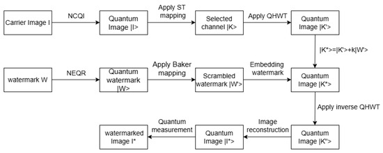
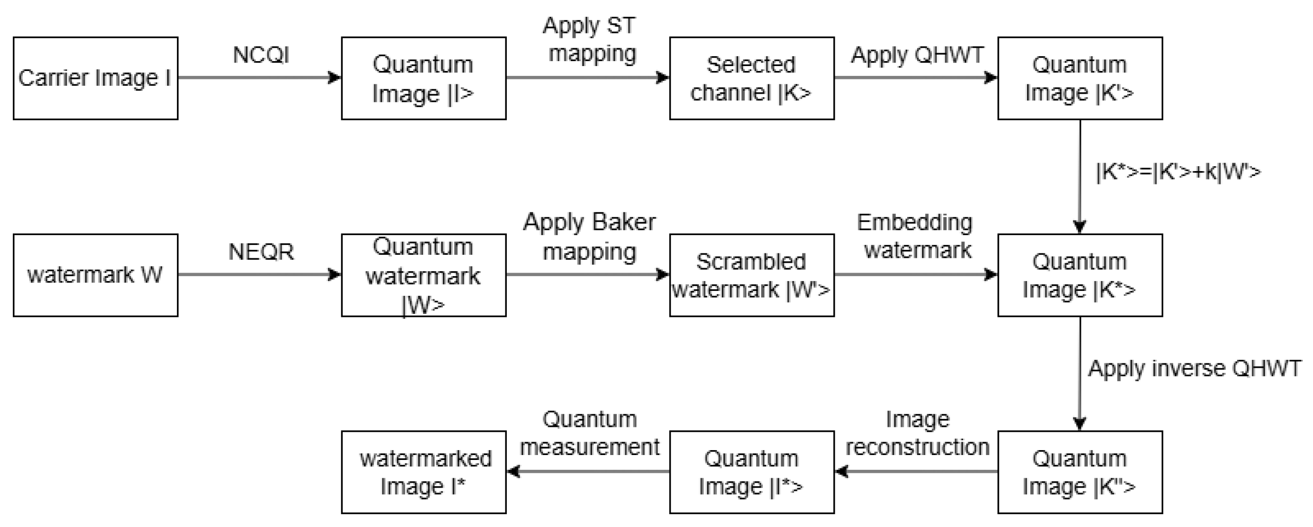
To embed a binary watermark image W of size into a color carrier image I of size , the embedding process is shown in Figure 9 with the following steps:
Figure 9.
Watermark embedding process.
Step 1: According to the NCQI model, a classical color carrier image I of size is represented as a quantum color carrier image .
Step 2: The initial value of a is selected, and the chaotic sequence is generated after Sinusoidal–Tent mapping j iterations. According to Equation (13), the chaotic sequence is converted to an integer sequence .
According to Equation (14), when the value of is 0, 1 or 2, the algorithm will correspondingly select the R channel, the G channel or the B channel of the quantum color image , for embedding the watermarked image, and the selected channel is noted as .
Step 3: According to the NEQR model, a classical binary watermark image W of size is represented as a quantum watermark image . The watermark image is scrambled using discrete baker mapping. The parameters are set as , and the scrambled watermark image is obtained.
Step 4: Perform quantum Haar wavelet transform on the quantum image to get the quantum image , as shown in Equation (16):
The frequency band of is divided into four parts: approximate subband, horizontal subband, vertical subband, and diagonal subband. The diagonal subband part is selected to embed the quantum watermark image with the embedding intensity k. The embedding expression is shown in Equation (17):
Step 5: Perform quantum Haar wavelet inversion on the quantum image to generate the quantum image containing the quantum watermark image .
Step 6: Reconstruct the quantum image with the remaining two channels of the quantum color carrier image to obtain the watermarked quantum color image .
Step 7: Perform quantum measurements on the quantum color image to obtain the classical color image .
3.2. Watermark Extraction
Because the quantum operations used in both image scrambling and watermark embedding are reversible, the recovery of the original image and the extraction of the watermark information can be realized by performing the corresponding scrambling and watermark embedding steps in reverse, which consists of the following steps.
Step 1: According to the NCQI model, the classical color carrier image of size is represented as a quantum color carrier image .
Step 2: Select a as the initial value and generate the chaotic sequence after Sinusoidal–Tent mapping j iterations. According to Equations (13) and (14), the channel with watermark information embedded in is selected.
Step 3: Perform quantum Haar wavelet transform on the quantum image with embedded watermark to get the quantum image .
Step 4: Extract the scrambled quantum watermark image according to Equation (18).
Step 5: Perform the inverse transformation of the quantum watermark image based on the discrete baker mapping as in Equation (19) to obtain the original quantum watermark image .
Step 6: Perform quantum measurements on the quantum watermarked image to obtain the classical image W.
3.3. Attacker Knowledge Scenarios
The algorithm in this paper needs to select the same initial value a as in the embedding stage when extracting the watermark, generate a chaotic sequence through the Sinusoidal–Tent mapping, and then determine the channel for embedding the watermark according to formulas Equations (13) and (14). The initial value a and the control parameter r of the ST mapping both belong to the “extraction key”. If the attacker does not have these keys, they cannot locate the channel where the watermark is embedded, nor can they perform the inverse transformation on the watermark of scrambling, and thus cannot extract the valid watermark. During the process of watermark extraction, there is no call to the original carrier image I, that is, the original carrier is not needed as a reference.
In summary, the watermark extraction of the algorithm in this paper relies on the initial value and the control parameter of the ST mapping, but does not require the original carrier image, which conforms to the definition of the knowledge scenario of a Semi-Blind attacker.
4. Numerical Simulation and Analysis
In order to evaluate the invisibility and robustness of the color image watermarking algorithms, various test metrics are used in the simulation experiments of this paper.
4.1. Watermark Evaluation Criteria
4.1.1. Peak Signal-to-Noise Ratio
Peak signal-to-noise ratio () [28] is an evaluation metric that measures the absolute error of two images and is usually used to evaluate the invisibility of watermarking algorithms, which is defined by the expression:
is the maximum gray value of the image, and is the mean squared error of image I and image W. and represent the pixel values of the carrier image I and the watermarked image W at position , respectively.
4.1.2. Structure Similarity Index Measure
The structural similarity index measure () [29] is able to evaluate the degree of distortion of an image and also the degree of similarity between two images. is a visual perception model that is more in line with the direct view of the human eye, and can be used to evaluate the invisibility of images containing watermarks, the definition of which is expressed as follows:
and denote the pixel mean of the carrier image I and the watermarked image W, respectively; and denote the variance of the image I and the image W, respectively; and is the covariance of the images I and W. The range of values is . If two images are exactly the same, the corresponding value of is equal to 1. This means that the closer the value of is to 1, the more similar the two images are and the more invisible the watermarking algorithm is.
4.1.3. Normalized Cross Correlation
The normalized cross correlation () [30] is a metric for evaluating the degree of similarity between two images and is used to assess the robustness of the watermarking algorithm against different attacks. It is defined and expressed as follows:
The range of values is , and the closer the value is to 1, the better the match between the two images and the more robust the watermarking algorithm is.
4.1.4. Learned Perceptual Image Patch Similarity
The measurement of image similarity constitutes a critical aspect of research in computer vision and deep learning. Although traditional measurement standards can reflect the similarity of images to a certain extent, they are usually based on the statistical properties of pixels or features, while ignoring human visual perception. To address this limitation, the Learned Perceptual Image Patch Similarity (LPIPS) metric was introduced.
The fundamental concept of LPIPS involves learning the inverse mapping from a generated image to its Ground Truth, thereby compelling the generator to reconstruct the inverse mapping of a real image from a synthetic one, with an emphasis on perceptual similarity. This metric leverages a neural network to extract high-level features of an image and compares the differences between these features, thus providing a more precise reflection of human visual perception.
The LPIPS score spans the range [0, 1]. When the LPIPS value is below 0.05, it indicates that the difference is nearly imperceptible. A lower LPIPS value serves as stronger evidence of the algorithm’s effectiveness in achieving invisibility.
4.2. Experiments on IBM Quantum Platform
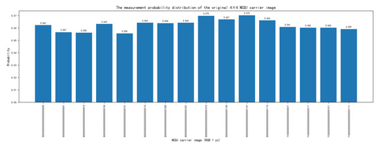
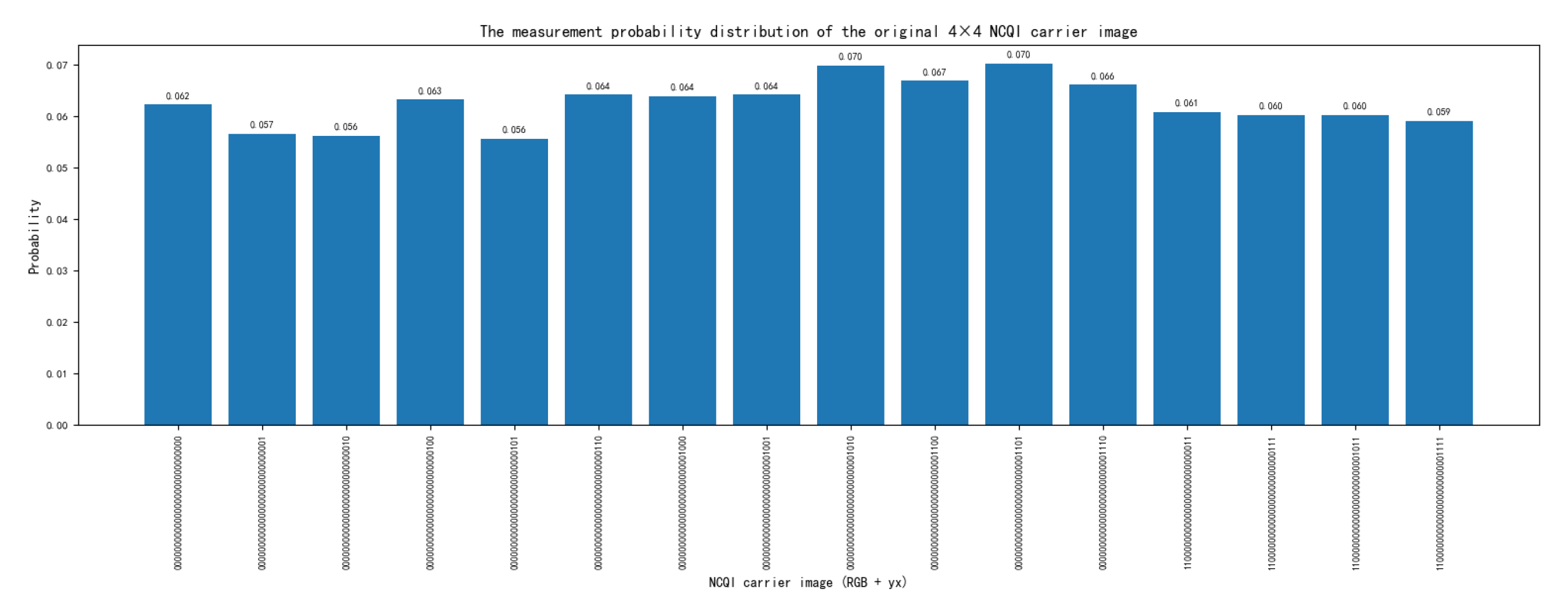
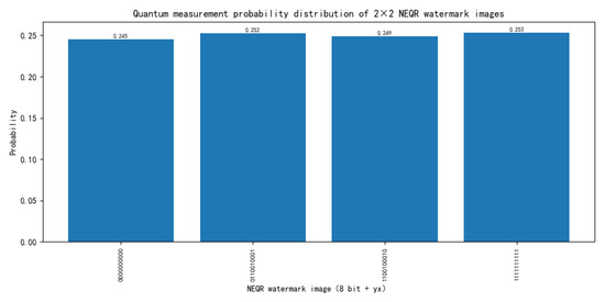
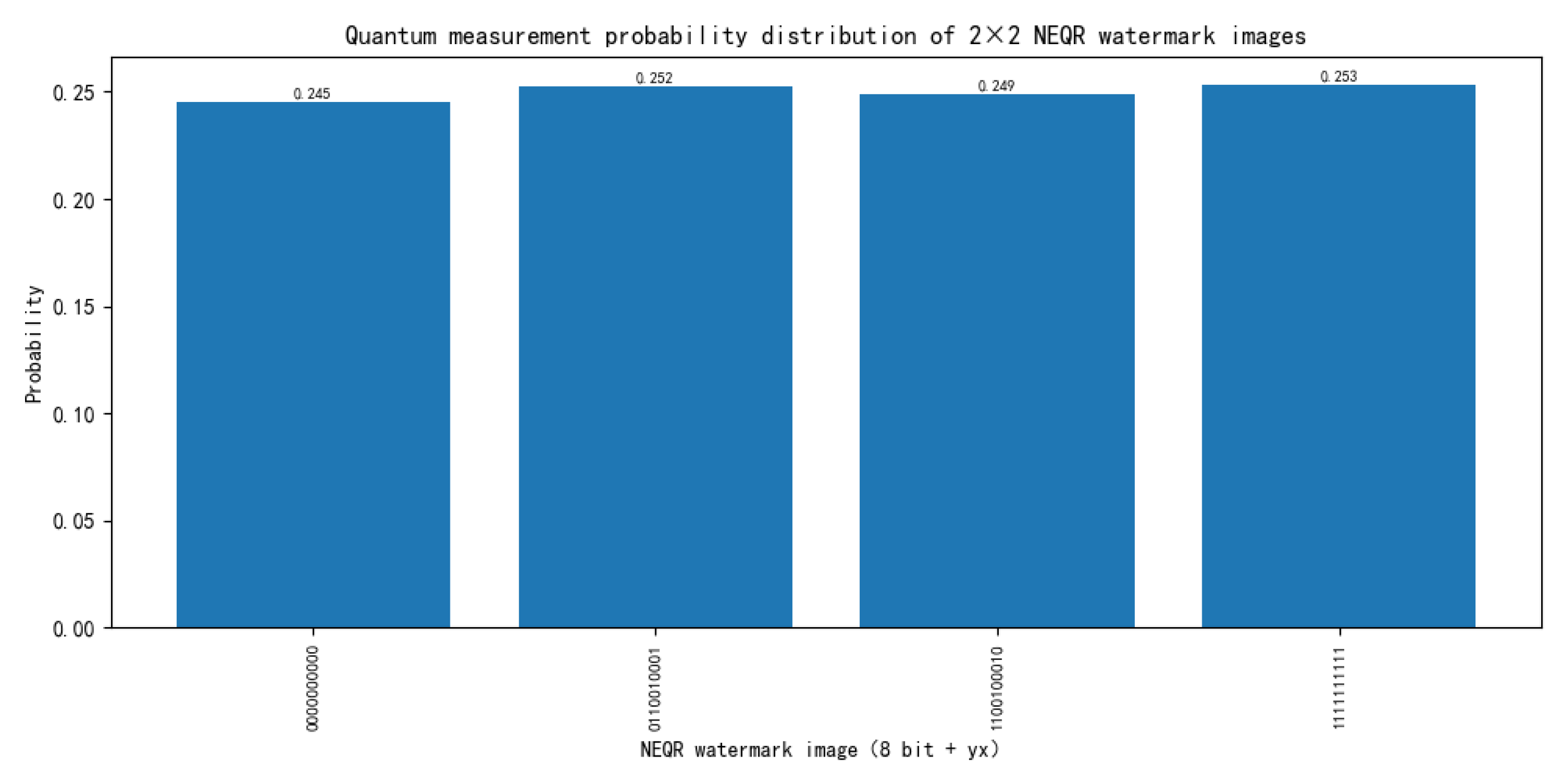
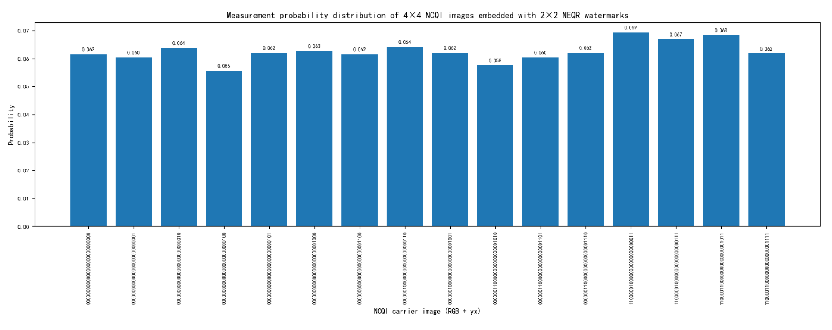
To verify the feasibility of the proposed scheme, relevant experiments were conducted on the IBM Quantum platform using the Qiskit toolkit. Due to the exponential increase in computational cost with respect to the number of qubits, the platform typically cannot efficiently simulate quantum circuits exceeding approximately 50 qubits. Therefore, on this platform, experiments were conducted using color carrier images and binary watermark images. The pixel values of the carrier image and the watermark image are shown in Equations (24) and (25). Figure 10 is the histogram of the measurement results after the carrier image was prepared, Figure 11 is the histogram of the measurement results after the binary watermark image was prepared, and Figure 12 is the histogram of the measurement results of the image after embedding the watermark.
Figure 10.
Measurement probability histogram of the carrier image.
Figure 11.
Measurement probability histogram of the watermark image.
Figure 12.
Measurement probability histogram of the image after embedding the watermark.
4.3. Experiment Results and Analysis
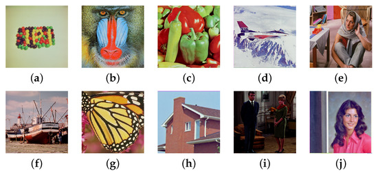
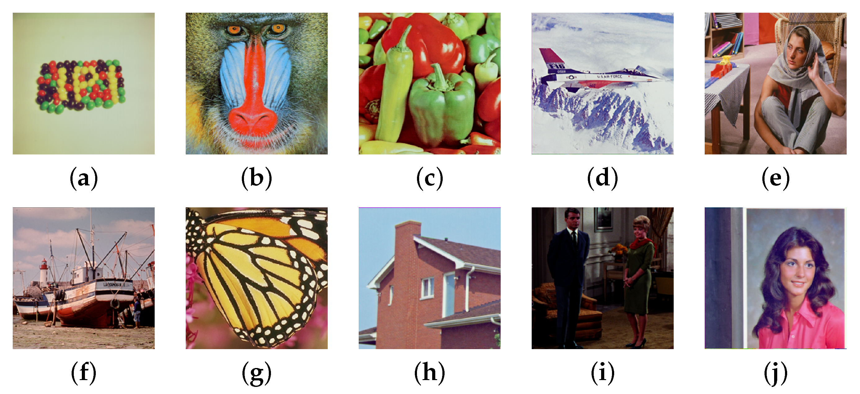
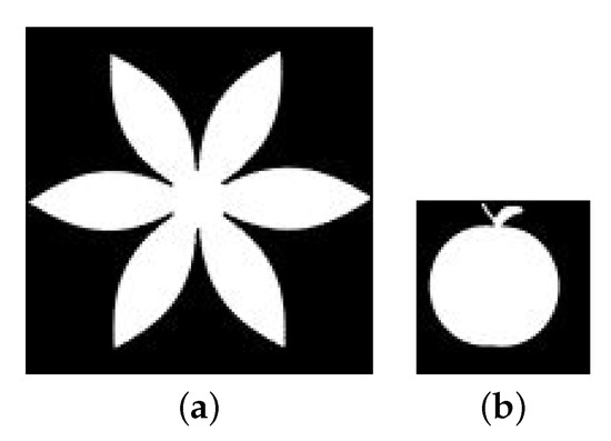
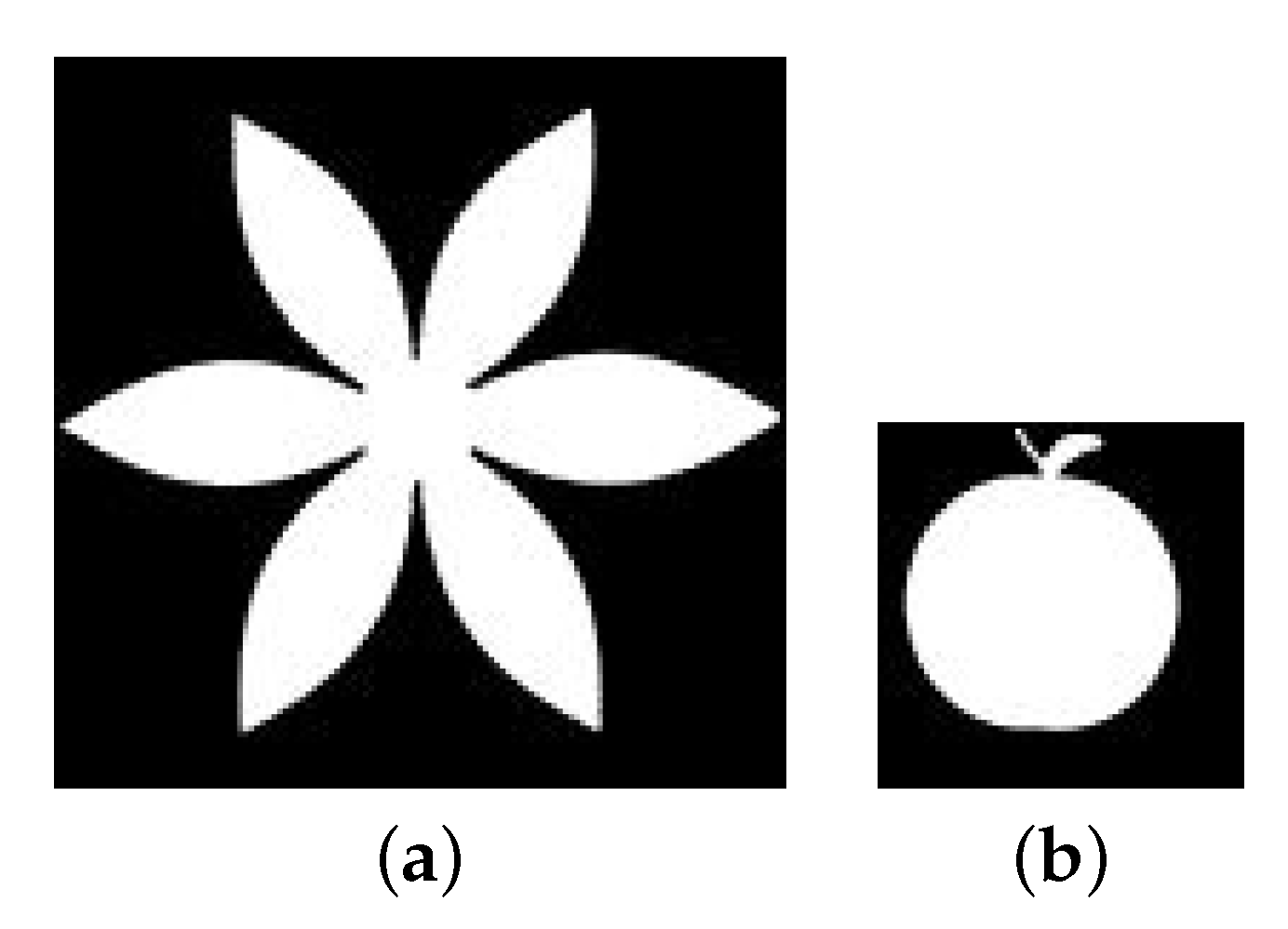
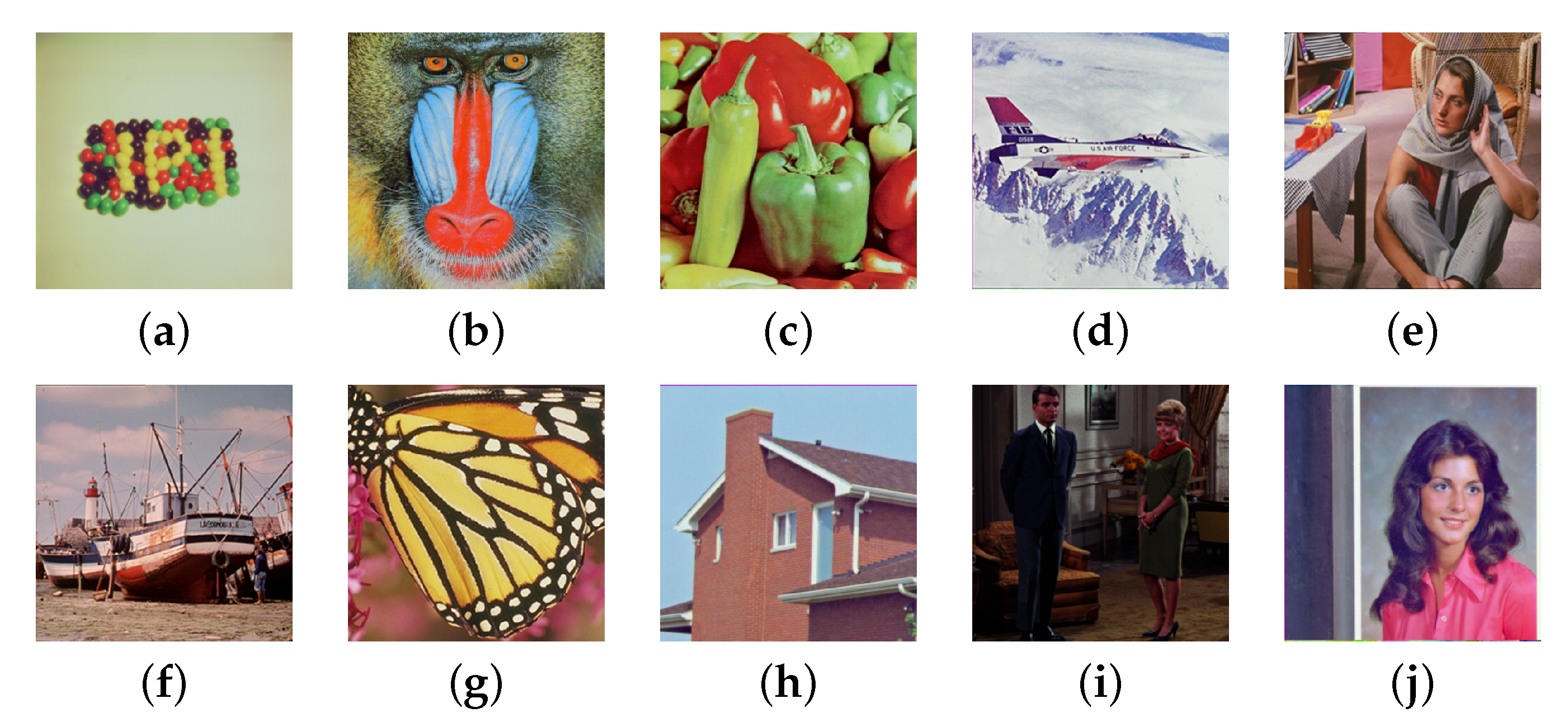
Simulation experiments were conducted on the computer using Python 3.8 64-bit software. In this experiment, 10 color images with a size of were selected from the USC-SIPI Image Database as carrier images, as shown in Figure 13a–j [31]. Binary images of size and were used as watermark images, as shown in Figure 14a,b. Set the initial value a = 0.325 in ST mapping and control parameter r = 0.1. The embedding strength in the algorithm was k = 0.01.
Figure 13.
Ten color images of size selected from the USC-SIPI Image Database [31]: (a) “beans”, (b) “mandril”, (c) “peppers”, (d) “airplane”, (e) “barbara”, (f) “boats”, (g) “butterfly”, (h) “house”, (i) “grace”, (j) “woman”.
Figure 14.
Watermarked images of sizes and : (a) “device”, (b) “apple”.
4.3.1. Analysis of Watermark Invisibility of Images
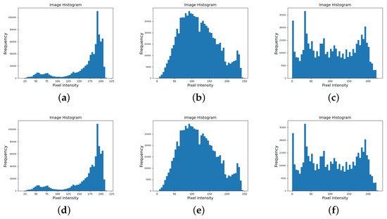
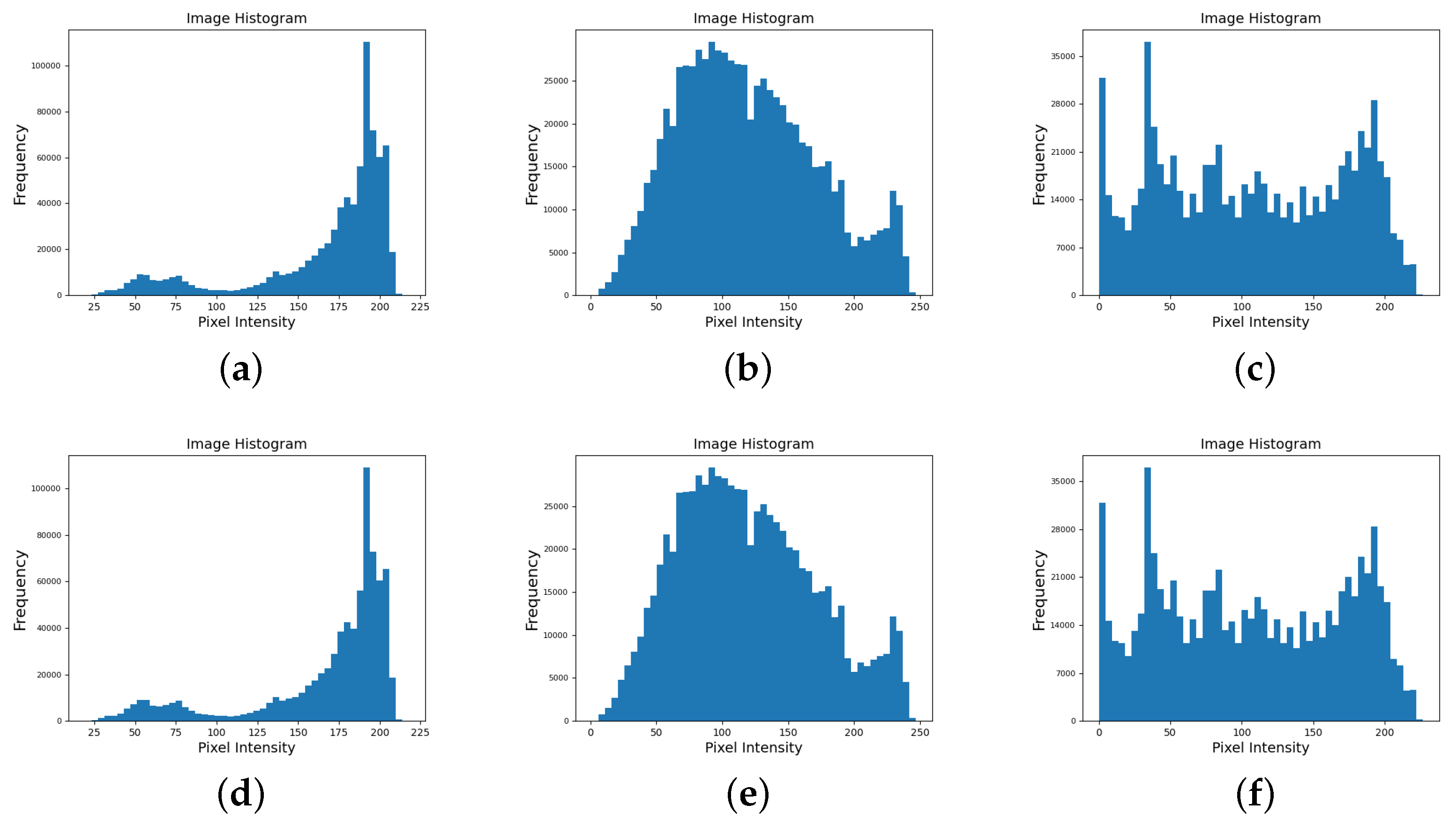
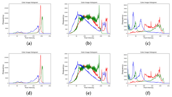
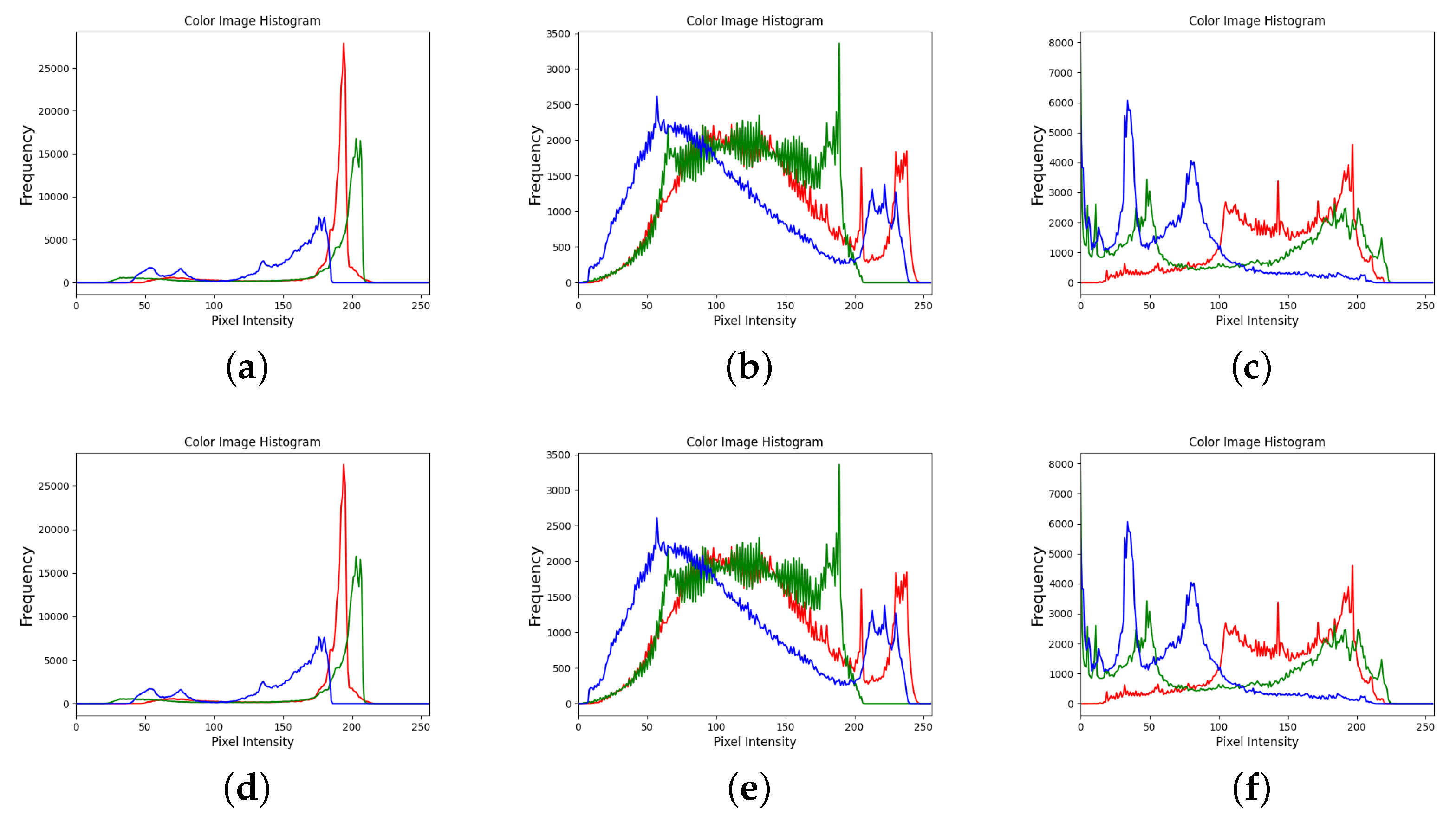
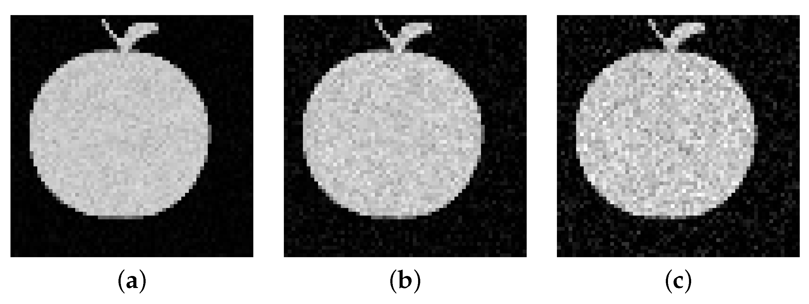
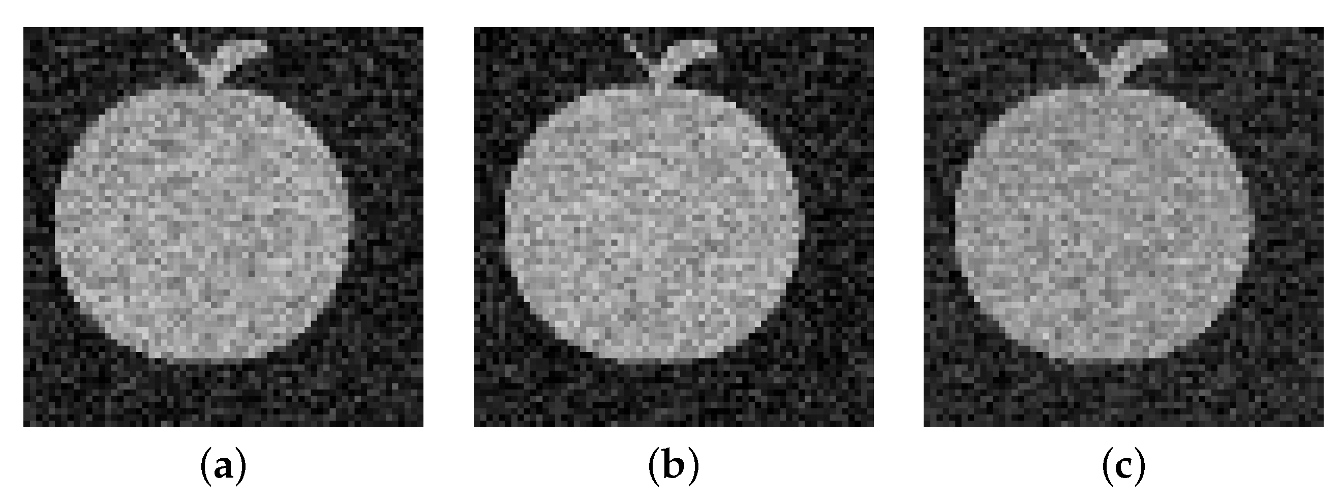
The two watermarked images are embedded into ten carrier images, respectively, Figure 15a–e shows the carrier images embedded with the watermarked image “device”, and Figure 15f–j shows the carrier images embedded with the watermarked image “apple”. It can be seen that the watermark-containing image has almost no difference from the original carrier image. Figure 16 illustrates the histograms corresponding to Figure 13a–c and Figure 15a–c, and Figure 17 illustrates the color histograms corresponding to Figure 13a–c and Figure 15a–c. The red, green and blue curves in the Figure 17 respectively represent the distribution frequencies of the pixel intensities of the red, green and blue channels in the image, and it can be seen that there is very little difference between the histograms of the original carrier image and the image containing the watermark.
Figure 15.
Images with watermarked “device”: (a) “beans”, (b) “mandril”, (c) “peppers”, (d) “airplane”, (e) “barbara”. Images with watermarked “apple”: (f) “boats”, (g) “butterfly”, (h) “house”, (i) “grace”, (j) “woman”.
Figure 16.
Histogram of the original carrier image: (a) “beans”, (b) “mandril”, (c) “peppers”. Histogram of the image with watermark: (d) “beans”, (e) “mandril”, (f) “peppers”.
Figure 17.
Color histogram of the original carrier image: (a) “beans”, (b) “mandril”, (c) “peppers”. Color histogram of the image with watermark: (d) “beans”, (e) “mandril”, (f) “peppers”.
Table 1 lists the PSNR values and SSIM values of 10 carrier images after embedding the watermarked images “device” and “apple”, respectively. It can be seen that the average PSNR values are 58.2245 dB and 63.3342 dB, the SSIM values are close to 1, and the LPIPS value is much less than 0.01 when the watermarks embedded in the carrier images are “device” and “apple”, respectively, indicating that the watermarking algorithm has better invisibility.
Table 1.
PSNR values and SSIM values of different carrier images.
4.3.2. Encryption Performance Evaluation
In this section, we will evaluate the performance of the algorithm, including entropy assessment, sensitivity testing, and key space analysis.
Information Entropy
In image processing, information entropy is an important indicator for describing the information volume of an image. It can be used to analyze the complexity and level of detail of images. The definition of information entropy is expressed by Equation (26), represents the information entropy of image I, and represents the probability of a pixel with a gray value of i appearing in the image. L is the total number of gray levels (for example, in an 8-bit gray image, ).
The carrier images beans, mandril, and peppers were selected to compare the information entropy of the images before and after watermark embedding. The results are shown in Table 2. It can be seen that the change in information entropy before and after watermark embedding is less than 0.01, indicating that the embedding of the watermark has very little impact on the distribution of image pixels, and the invisibility of the watermark algorithm is excellent.
Table 2.
Comparison of information entropy.
Sensitivity Test
The article does not encrypt the carrier image, but realizes the random selection of the embedding channel through Sinusoidal–Tent mapping and the watermark scrambling through baker mapping. These two links are essentially watermark encryption preprocessing dependent on key control. The security of the key directly determines whether the watermark can be illegally extracted. Therefore, it is necessary to verify the anti-cracking ability of the algorithm through sensitivity testing and key space analysis.
Perturbed the initial value of the ST mapping. When a is perturbed by and becomes , calculate the NCC between the watermarks extracted by the carrier images beans, mandril, and peppers, respectively, under the conditions of and after embedding the watermark and the original watermark. The results are shown in Table 3. It can be seen that the NCCs of the extracted watermarks are all less than 0.3, which means that a slight change in the key will cause the extracted watermarks to be completely distorted. Therefore, the algorithm in this paper meets the security requirement of “one key per time”.
Table 3.
Sensitivity test results.
Key-Space Size Analysis
The algorithm key includes the initial value a of the ST mapping (with an accuracy of and a range of ) and the control parameter r (with an accuracy of and a range of ). Therefore, the total key space is , far more than the of the brute force threshold value.
4.3.3. Anti-Attack Analysis of Watermark Images
Robustness analysis and testing play a critical role in image processing, as they evaluate an algorithm’s ability to withstand various attacks and malicious manipulations, thereby providing insight into its overall security performance.
Noise Attack
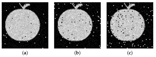
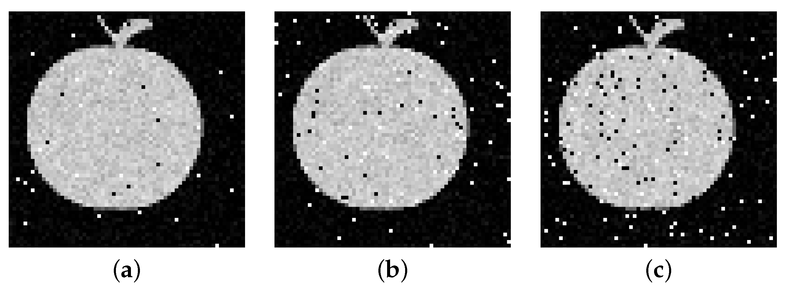
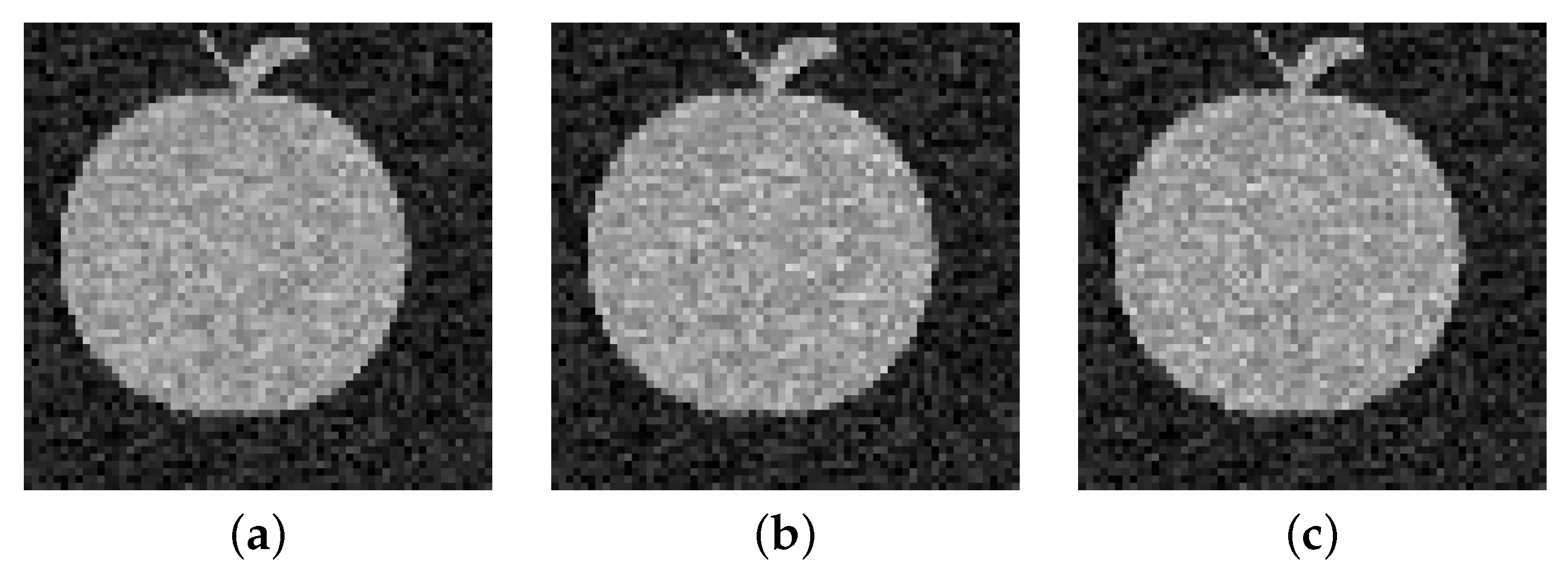
Robustness serves as a critical metric in assessing the performance of watermarking algorithms, particularly in their ability to resist noise attacks, which constitutes an essential aspect of algorithm validation. In this study, carrier images containing watermarks were subjected to pretzel noise attacks at varying intensities. The Normalized Cross-Correlation (NCC) value, which quantifies image similarity, approaches 1 when the two images are highly similar. The subsequent table presents the NCC values of watermarked images extracted from carrier images under different noise intensities after noise addition. Figure 18 illustrates the extracted watermark under varying noise intensities. As evident from Table 4, the proposed watermarking algorithm demonstrates robust performance against noise attacks.
Figure 18.
Salt-and-Pepper noise attack test results: (a) noise intensity 0.01, (b) noise intensity 0.03, (c) noise intensity 0.05.
Table 4.
Salt-and-Pepper noise attack test results.
JPEG Compression Attack
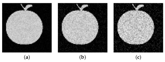
The watermarked carrier image is processed using JPEG compression with quality factor parameters of 90, 70, and 50, respectively, and the experimental results are shown in Table 5. Figure 19 depicts the watermarked image extracted from the carrier image under JPEG compression attacks with varying parameters. Even at a quality factor of 50, the extracted watermark remains visually intact and clear, with corresponding NCC values exceeding 0.9790. These findings confirm the high effectiveness of the proposed watermarking algorithm in resisting JPEG compression attacks.
Table 5.
JPEG compression attack test results.
Figure 19.
JPEG compression attack test results: (a) QF 90, (b) QF 70, (c) QF 50.
Filtering Attack
The watermark image is interfered with by using a median filter with a filtering window of 3×3. Figure 20 shows the watermarks extracted from different carrier images subject to filtering attacks, and Table 6 shows the corresponding NCC values. The NCC values corresponding to the extracted watermark images are all above 0.95. The results show that the color image algorithm proposed in this paper can resist filtering attacks quite well.
Figure 20.
Filtering attack test results: (a) beans, (b) mandril, (c) peppers.
Table 6.
Filtering attack test results.
Scaling Attack
The carrier image beans with watermarks were respectively subjected to scaling attacks of 1.5 times, 1.8 times and 2 times. The extracted watermark images are shown in Figure 21, and the corresponding NCC values are shown in Table 7. The NCC values corresponding to the extracted watermark images are all above 0.94. The results show that the color image algorithm proposed in this paper can resist scaling attacks quite well.
Figure 21.
Scaling attack test results: (a) 1.5 times, (b) 1.8 times, (c) 2 times.
Table 7.
Scaling attack test results.
4.3.4. Ablation Study
The algorithm proposed in this paper integrates three core techniques: chaotic equations, quantum equations, and baker mapping. To systematically assess the contribution of each technique to the overall performance, an ablation study was conducted. By sequentially removing each key component and comparing the resulting performance, the individual impact of chaotic equations, quantum equations, and baker mapping on the watermarking algorithm was quantitatively analyzed.
Four sets of comparative experiments were designed to evaluate the impact of removing different key technologies:
- 1.
- Complete algorithm: Chaotic equation (ST mapping) + QDWT + baker mapping.
- 2.
- No chaotic equation: Only QDWT + baker mapping are used (the ST mapping is removed, and a fixed-channel R is selected for watermark embedding).
- 3.
- No quantum equation: Only ST mapping + baker mapping are applied (QDWT is replaced with traditional DWT).
- 4.
- No baker mapping: Only ST mapping + QDWT are employed (the watermark is embedded directly without image scrambling).
The PSNR values, SSIM values, LPIPS values of the carrier images after embedding watermarks in four groups of experiments, and the NCC values of the watermark images after being attacked by noise are shown in Table 8. It can be seen that since the ST mapping randomly selects the embedding channel, QDWT provides a better frequency-domain representation than traditional DWT. Image scrambling makes the watermark distribution more uniform. The three key technologies all make significant contributions to the improvement of the PSNR value. After being attacked by noise, the ST mapping has a relatively small improvement on the NCC value. However, due to the multi-resolution feature of QDWT, the watermark is distributed more reasonably in the frequency domain. The dispersion strategy in the spatial domain effectively reduces the impact of local damage. The quantum equation and Baker mapping contribute significantly to the improvement of the algorithm’s anti-noise attack ability.
Table 8.
Invisibility comparison of different algorithms.
Furthermore, although ST mapping offers only moderate improvement in NCC values after attacks, the multi-resolution characteristics of QDWT enable a more rational watermark distribution in the frequency domain. The dispersion strategy in the spatial domain effectively mitigates the effects of localized damage. Overall, both the quantum equation and baker mapping play crucial roles in enhancing the algorithm’s robustness against various types of attacks.
Thus, the three key technologies of chaotic equation, quantum equation and baker mapping all play important roles in the algorithm proposed in this paper. In fact, Sinusoidal–Tent mapping exhibits complex chaotic behavior within the range of control parameters. The generated chaotic sequence has a high degree of randomness and unpredictability, significantly enhancing the security of the algorithm. Quantum discrete wavelet transform can better capture the local features of signals and provide more frequency and scale information, and has more advantages when dealing with attacks. Baker mapping effectively disrupts the pixel arrangement order by segmenting the image and remapping sub-blocks, destroys the local correlation of the image, and significantly enhances the concealment and anti-attack ability of the watermark.
4.3.5. Sensitivity Analysis
Let k take 0.005, 0.01, 0.015, and 0.002, respectively, to compare the PSNR, SSIM, and LPIPS of the watermarking algorithm under different embedding strengths k and the NCC under noise attack(noise intensity 0.01). The results are shown in Table 9.
Table 9.
Sensitivity analysis of embedding strength k.
As can be seen from Table 9, when k increases, the invisibility (PSNR, SSIM, LPIPS) decreases, but the robustness (NCC) improves. When k = 0.01, PSNR > 63, LPIPS < 0.015, and NCC > 0.97, which is the optimal equilibrium. Therefore, k = 0.01 was selected for the experiment.
4.3.6. Performance Evaluation of Different Image Sizes
The sizes of the selected carrier images were , and , respectively, and the size of the watermark image is . The PSNR, SSIM, LPIPS of the watermarking algorithm and the time required for the watermark embedding process under images of different sizes of carriers were compared, and the results are shown in Table 10:
Table 10.
Performance evaluation of different image sizes.
As can be seen from Table 10, when the size of the carrier image keeps increasing, the running time remains very fast, and large-sized images still maintain high PSNR values and low LPIPS values, verifying the scalability of the algorithm.
4.3.7. Comparative Analysis
For the same watermarking apple, the PSNR values, SSIM values, and NCC value for resisting noise attacks of various carrier images are presented in Table 11. The watermarking algorithm proposed in this paper utilizes a dual chaotic mechanism, enhancing security. Compared with the watermarking algorithms based on quantum Haar wavelet transform and Arnold scrambling [15], the watermarking algorithms based on quantum cosine transform and sinusoidal tent mapping [16], and the color image watermarking algorithms based on quantum cosine transform and edge detection technology [17]. It is found that the PSNR and SSIM values of the watermarking algorithm in this paper have superiority. This indicates a higher level of invisibility for the proposed method.
Table 11.
PSNR values, SSIM values, and NCC values for different carrier images.
4.3.8. Computational Complexity Analysis
The complexity of quantum computing depends on the number of basic quantum gates, the coefficient of ignoring complexity, and the complexity of the computational preparation work. In the color image watermarking algorithm proposed in this paper, the computational complexity is mainly related to the quantum image scrambling operation and QHWT. In this paper, discrete baker mapping is used for quantum image scrambling. The quantum circuit of the quantum Baker scrambling algorithm consists of a specific number of quantum swap gates and Fredkin gates. Among them, quantum swap gates used , and Fredkin gates used . According to the known research conclusion [32], one quantum swap gate is equivalent to three CNOT gates, and one Fredkin gate can be implemented through five two-qubit gates. Therefore, the total complexity is , while ignoring the complexity coefficient, the complexity of quantum Baker scrambling is . The row decomposition of the first-level QHWT needs to act on the n-bit row coordinate qubit and the q-bit color information qubit. First, the Hadamard gate needs to act on all n+q qubits one by one to generate gate operations. Secondly, the positive shift permutation matrix needs to be decomposed into basic permutation units, and each unit requires basic quantum gates. Therefore, the total number of gates in a single iteration of row decomposition is . Similarly, column decomposition requires repeating the above operation for n-bit coordinate qubits and q-bit color information qubits, with the number of gates also being . Therefore, after the superposition of the two, the overall computational complexity of the first-order quantum Haar wavelet transform is ultimately . For an image of size , the computational complexity of traditional discrete wavelet transform is , the computational complexity of quantum discrete cosine transform is also , while the computational complexity of the quantum wavelet transform used in this paper is , which greatly improves the computational complexity of the algorithm.
5. Conclusions
Aiming to address the high complexity of existing image watermarking algorithms and low efficiency in image scrambling algorithms, this study proposes a novel color image watermarking algorithm that integrates quantum discrete wavelet transform with Sinusoidal–Tent mapping and baker mapping. The algorithm first employs Sinusoidal–Tent mapping to generate a chaotic sequence, which determines the channels for embedding the watermark. Subsequently, a one-level quantum Haar wavelet transform is applied to the selected channels to decompose the image. The watermarked image is then scrambled using discrete baker mapping, and the scrambled result is embedded into the diagonal subbands of the decomposed image. Experimental results demonstrate that the proposed algorithm exhibits excellent invisibility and robustness. Additionally, the speed of image scrambling has been substantially enhanced while effectively reducing computational complexity. The computational complexity of the quantum wavelet transform utilized in this study is . Although the index value obtained in simulation experiments is acceptable, reducing the computational complexity of the color image watermarking scheme to a lower level remains a key focus for further research. In terms of security, asymmetric watermarking technology can be further leveraged. Specifically, distinct keys are employed during the processes of watermark embedding and detection, thereby enhancing the overall security of the watermarking system.
Author Contributions
Conceptualization, W.L.; Methodology, Z.L.; Software, Y.Y. and W.Z.; Validation: Y.Y.; Formal Analysis, Z.L. and W.L.; Data Curation, Y.Y.; Writing—Original Draft Preparation, Y.Y.; Writing—Review and Editing, Y.Y., W.Z., Z.L. and W.L.; Visualization, Y.Y. and W.Z.; Supervision, Z.L. and W.L. All authors have read and agreed to the published version of the manuscript.
Funding
This paper is supported by a Key-Area Research and Development Program of Guangdong Province with grant no. 2024B1111060004, Shenzhen Science and Technology Program (Grant No. 202206193000001-20220817184157001), the Fundamental Research Funds for the Central Universities, and the “Hundred-Talent Program” of Sun Yat-sen University.
Data Availability Statement
The data that support the findings of this study are available from the corresponding author upon reasonable request.
Conflicts of Interest
The authors declare that there are no financial interests, commercial affiliations, or other potential conflicts of interest that could have influenced the objectivity of this research or the writing of this paper.
Abbreviations
The following abbreviations are used in this manuscript:
| FRQI | Flexible Representation of Quantum Images |
| NEQR | Novel Enhanced Quantum Representation |
| PSNR | Peak signal-to-noise ratio |
| SSIM | Structural similarity index measure |
| NCC | Normalized Cross Correlation |
| LPIPS | Learned Perceptual Image Patch Similarity |
| QHWT | Quantum Haar wavelet transform |
References
- Gea-Banacloche, J. Hiding messages in quantum data. J. Math. Phys. 2002, 43, 4531–4536. [Google Scholar] [CrossRef] [Scilit]
- Venegas-Andraca, S.E.; Bose, S. Storing, processing, and retrieving an image using quantum mechanics. Proc. SPIE 2003, 5105, 137–147. [Google Scholar] [CrossRef] [Scilit]
- Le, P.Q.; Dong, F.Y.; Hirota, K. Hiding messages in quantum data. Quantum Inf. Process. 2011, 10, 63–84. [Google Scholar] [CrossRef] [Scilit]
- Zhang, Y.; Lu, K.; Gao, Y.H.; Wang, M. NEQR: A novel enhanced quantum representation of digital images. Quantum Inf. Process. 2013, 12, 2833–2860. [Google Scholar] [CrossRef] [Scilit]
- Jiang, N.; Wang, L. Quantum image scaling using nearest neighbor interpolation. Quantum Inf. Process. 2015, 14, 1559–1571. [Google Scholar] [CrossRef] [Scilit]
- Sang, J.Z.; Wang, S.; Li, Q. A novel quantum representation of color digital images. Quantum Inf. Process. 2017, 16, 42. [Google Scholar] [CrossRef] [Scilit]
- Li, P.C.; Liu, X. Color image representation model and its application based on an improved FRQI. Int. J. Quantum Inf. 2018, 16, 1850005. [Google Scholar] [CrossRef] [Scilit]
- Li, R.N.; Xiao, Y.H.; Zhang, C.; Song, T.Y.; Hu, C.Q. Cryptographic algorithms for privacy-preserving online applications. Math. Found. Comput. 2018, 1, 311–330. [Google Scholar] [CrossRef] [Scilit]
- Song, X.H.; Wang, S.; Liu, S.; Abd El-Latif, A.A.; Niu, X.M. A dynamic watermarking scheme for quantum images using quantum wavelet transform. Quantum Inf. Process. 2013, 12, 3689–3706. [Google Scholar] [CrossRef] [Scilit]
- Zhang, W.W.; Gao, F.; Liu, B.; Wen, Q.Y.; Chen, H. A watermark strategy for quantum images based on quantum fourier transform. Quantum Inf. Process. 2013, 12, 793–803. [Google Scholar] [CrossRef] [Scilit]
- Yang, Y.G.; Xu, P.; Tian, J.; Zhang, H. Analysis and improvement of the dynamic watermarking scheme for quantum images using quantum wavelet transform. Quantum Inf. Process. 2014, 13, 1931–1936. [Google Scholar] [CrossRef] [Scilit]
- Yan, F.; Iliyasu, A.; Sun, B.; Venegas-Andraca, S.E.; Dong, F.Y.; Hirota, K. A duple watermarking strategy for multi-channel quantum images. Quantum Inf. Process. 2015, 14, 1675–1692. [Google Scholar] [CrossRef] [Scilit]
- Wang, S.; Song, X.H.; Niu, X.M. Quantum Cosine Transform Based Watermarking Scheme for Quantum Images. Chin. J. Electron. 2015, 24, 321–325. [Google Scholar] [CrossRef] [Scilit]
- Hu, W.W.; Zhou, R.G.; El-Rafei, A.; Jiang, S.X. Quantum Image Watermarking Algorithm Based on Haar Wavelet Transform. IEEE Access 2019, 7, 121303–121320. [Google Scholar] [CrossRef] [Scilit]
- Su, Y.H.; Xia, T.; Wang, X.M.; Qian, X.H. New Image Watermarking Algorithm Based on Quantum Wavelet Transform. Comput. Sci. (In Chinese) 2023, 50, 8. [Google Scholar] [CrossRef]
- Zeng, P.P.; Zhou, X.M.; Zhong, D.F.; Chen, S.H.; Gong, L.H. Color watermarking algorithm combining the quantum discrete cosine transform with the sinusoidal–tent map. Front. Phys. 2024, 11, 1315765. [Google Scholar] [CrossRef] [Scilit]
- Li, Z.Z.; Li, Y.J.; Zhang, Z.; Wang, D.F.; Wang, J.T. Quantum color image watermarking scheme based on quantum discrete cosine transform. Phys. Scr. 2024, 99, 115113. [Google Scholar] [CrossRef] [Scilit]
- Wang, L.N.; Banerjee, S.; Cao, Y.H.; Mou, J.; Sun, B. A new self-embedding digital watermarking encryption scheme. Nonlinear Dyn. 2024, 112, 8637–8652. [Google Scholar] [CrossRef] [Scilit]
- Artiles, J.A.P.; Chaves, P.B.D.; Cecilio, P. Robust image watermarking algorithm using chaotic sequences. J. Inf. Secur. Appl. 2022, 68, 103219. [Google Scholar] [CrossRef] [Scilit]
- Jackson, J.; Perumal, R. A robust image encryption technique based on an improved fractional order chaotic map. Nonlinear Dyn. 2025, 113, 7277–7296. [Google Scholar] [CrossRef] [Scilit]
- Teng, L.; Wang, X.Y.; Xian, Y.J. Image encryption algorithm based on a 2D-CLSS hyperchaotic map using simultaneous permutation and diffusion. Inf. Sci. 2022, 605, 71–85. [Google Scholar] [CrossRef] [Scilit]
- Zhou, N.R.; Cheng, W.W.; Yan, X.Y.; Wang, Y.Q. Bit-Level Quantum Color Image Encryption Scheme with Quantum Cross-Exchange Operation and Hyper-Chaotic System. Quantum Inf. Process. 2018, 17, 137. [Google Scholar] [CrossRef] [Scilit]
- Ran, Q.W.; Wang, L.; Ma, J.; Tian, L.Y.; Yu, S.Y. A Quantum Color Image Encryption Scheme Based on Coupled Hyper-Chaotic Lorenz System with Three Impulse Injections. Quantum Inf. Process. 2018, 17, 188. [Google Scholar] [CrossRef] [Scilit]
- Lu, A.P.; Li, P.C. Quantum Encryption Scheme for Color Images Based on Chaotic Sequences. Comput. Digit. Eng. (In Chinese) 2021, 49, 692–697. [Google Scholar]
- Lal, S.; Kumar, S. Solution of Abel’s integral equation by modified Taylor wavelet with error analysis. Math. Found. Comput. 2024, 7, 336–349. [Google Scholar] [CrossRef] [Scilit]
- Zhang, Q.; Shao, J. Lyapunov type inequalities for nonlinear fractional Hamiltonian systems in the frame of conformable derivatives. Math. Found. Comput. 2024, 7, 284–296. [Google Scholar] [CrossRef] [Scilit]
- Jiang, Z.Y.; Liu, X.B. Image Encryption Algorithm Based on Discrete Quantum Baker Map and Chen Hyperchaotic System. Int. J. Theor. Phys. 2023, 62, 22. [Google Scholar] [CrossRef] [Scilit]
- Su, Q.T.; Liu, D.C.; Sun, Y.H. A robust adaptive blind color image watermarking for resisting geometric attacks. Inf. Sci. 2022, 606, 194–212. [Google Scholar] [CrossRef] [Scilit]
- Zhang, X.B. Improved Non-local Means Using Structural Similarity for Image Denoising. Circuits Syst. Signal Process. 2025, 44, 2706–2736. [Google Scholar] [CrossRef] [Scilit]
- Sahiner, A.; Maslouhi, M.; Yilmaz, N. An application of exponential smoothing technique in image restoration. Math. Found. Comput. 2024, 8, 923–933. [Google Scholar] [CrossRef] [Scilit]
- SIPI Image Database. Available online: https://sipi.usc.edu/database/ (accessed on 16 July 2024).
- Hou, C.G.; Liu, X.B.; Feng, S.Y. Quantum image scrambling algorithm based on discrete Baker map. Mod. Phys. Lett. A 2020, 35, 2050145. [Google Scholar] [CrossRef] [Scilit]


Disclaimer/Publisher’s Note: The statements, opinions and data contained in all publications are solely those of the individual author(s) and contributor(s) and not of MDPI and/or the editor(s). MDPI and/or the editor(s) disclaim responsibility for any injury to people or property resulting from any ideas, methods, instructions or products referred to in the content. |
© 2025 by the authors. Licensee MDPI, Basel, Switzerland. This article is an open access article distributed under the terms and conditions of the Creative Commons Attribution (CC BY) license.