Review

Thermonuclear Fusion Reactor Plasma-Facing Materials under Conditions of Ion Irradiation and Plasma Flux

by
Boris I. Khripunov
*,
Vasily S. Koidan
and
Evgeny V. Semenov
National Research Center “Kurchatov Institute”, 123182 Moscow, Russia
*
Author to whom correspondence should be addressed.
Symmetry 2021, 13(11), 2081; https://doi.org/10.3390/sym13112081
Submission received: 6 July 2021 / Revised: 20 October 2021 / Accepted: 22 October 2021 / Published: 3 November 2021
(This article belongs to the Special Issue Symmetry in Physics of Plasma Technologies)

Abstract

:
A review of experimental studies carried out at the NRC “Kurchatov Institute” on plasma-facing thermonuclear fusion reactor materials is presented in the paper. An experimental method was developed to produce high-level radiation damage in materials simulating the neutron effect by surrogate irradiation with high-energy ions. Plasma-surface interaction is investigated on materials irradiated to high levels of radiation damage in high-flux deuterium plasma. The total fluence of accelerated ions (3–30 MeV, 4He2+, 12C3+, 14N3+, protons) on the samples was 1021–1023 m−2. Experiments were carried out on graphite materials, tungsten, and silicon carbide. Samples have been obtained with a primary defect concentration from 0.1 to 100 displacements per atom, which covers the predicted damage for the ITER and DEMO projects. Erosion dynamics of the irradiated materials in steady-state deuterium plasma, changes of the surface microstructure, and deuterium retention were studied using SEM, TEM, ERDA, TDS, and nuclear backscattering techniques. The surface layer of the materials (3 to hundreds µm) was investigated, and it was shown that the changes in the crystal structure, the loss of their symmetry, and diffusion of defects to grain boundaries play an important role. The most significant results are presented in the paper as an overview of our previous work for many years (carbon and tungsten materials) as well as the relatively recent results (silicon carbide).

1. Introduction

Thermonuclear reactor based on deuterium-tritium (DT) fusion reaction is aimed to produce plasma with parameters providing high enough particle energy and density for the reaction to take place. The generation of high-energy neutrons is an intrinsic factor of the reaction, and therefore the reactor structure will undergo irradiation and would suffer from the damage induced by the neutrons with appropriate consequences for the properties of the structure materials. The first wall of the tokamak-reactor will face the most severe damaging conditions because the magnetic confinement does not ensure total isolation of the material wall facing the plasma, which accepts both plasma radiation and particle fluxes. The choice for the ITER reactor under construction nowadays is made in favor of beryllium for the first wall and tungsten for the divertor coating. Important neutron fluence (≥1026 m−2) is characteristic of the tokamak-reactor operating in a steady state. This brings an accumulation of radiation damage in the structure materials thus leading to degradation of their physical and mechanical properties. Therefore, the problem to obtain materials capable of operating in a fusion reactor for a durable time under neutron irradiation and plasma fluxes is actually of the most acuity [1,2,3].
No neutron sources of the needed energy and intensity are actually available to produce damage at the level predicted for a long-term operation of a fusion tokamak-reactor. There are different principal approaches to obtaining high-level radiation damage in materials for experimental investigations. The first one relates to a fusion neutron source of sufficiently high intensity, but it is not yet realized today. Second, fission neutrons from a fast reactor may be taken. In this case, a long irradiation time of about a one-year-scale period is needed to accumulate radiation damage at a high enough level [4]. Finally, fast charged particles from accelerators (protons as well as heavy ions) suit well for experimental modeling of radiation damage of fusion materials [5]. The ion irradiation has been offered long ago for simulations of the neutron effect on the materials for nuclear applications [6]. Charged particles accelerated to high energies present an efficient means for the production of displacement damage for a reasonable experimental time period at the levels being of interest for fusion research. This method is widely used in fusion-oriented investigations [7,8,9,10,11,12,13,14]. The method has been also taken in our research and it was developed on the basis of experimental facilities at NRC “Kurchatov Institute”. To date, ion irradiated samples at a level quantified in displacements per atom within an interval from 0.1 to 100 displacements per atom (dpa) have been obtained thus covering the whole range corresponding, namely, to the ITER and DEMO projects.
We conducted experimental research on the relation between the plasma effect on plasma-facing materials and the level of radiation damage. Ion irradiation experiments were performed using the U-150 cyclotron providing high-energy particles from several MeV to 60 MeV. Radiation damaged samples were studied on the linear plasma device LENTA simulating tokamak divertor plasma conditions. Plasma-facing materials actually considered as candidates for application in tokamak reactors have been studied: carbon-based materials have been examined at the initial stage [15] and tungsten at the ongoing stage of the work [16,17,18,19]. Silicon carbide was also included in the study.
The review is structured as follows: Section 2 describes material choice, research methods, and facilities. Section 3 contains major results on irradiated carbon materials exposed to deuterium plasma. Section 4 summarizes results on tungsten samples irradiated by different ion types followed by deuterium plasma exposure. The results of plasma exposure on proton-irradiated silicon carbide samples are presented in Section 5. Finally, Section 6 discusses the obtained results and concludes the review.

2. Experimental Method and Materials

The research is based on a complex method using irradiation of materials with accelerated high-energy ions to produce damage at the first stage which is followed by exposure of the irradiated samples to steady-state plasma simulating the tokamak scrape-off-layer (SOL) and divertor conditions. The ion irradiation generates displacements of atoms in the material structure at a rate of several orders higher than neutrons, and this makes it possible to achieve high levels of radiation damage at a reasonable time of an experimental run. Using this method, we can accumulate radiation damage equivalent to fast neutron irradiation at a dose of up to 1022 cm−2 in a few days’ operations of the cyclotron. The primary defects in the materials are generated in a near-surface layer at a depth of ion range depending on the type of ions and on their energy.
The work included the study of carbon-based materials and then of different tungsten grades. Silicon carbide (SiC) was also studied as a low-activated candidate material. For this, accelerated carbon ions were taken to produce damage in carbon-based materials (graphites). Different ion species have been used in irradiations of tungsten, namely, 4He2+, 12C3+, 14N3+, and protons. Silicon carbide was irradiated with accelerated protons.
The linear plasma machine LENTA [16] was used at the second stage of the experimental procedure to process the irradiated materials in deuterium plasma and to study their erosion in conditions relevant to SOL of a tokamak reactor. The plasma simulator LENTA generated plasma in a steady state discharge powered by electron beam providing deuterium current on the surface of the materials under study at jion = 1017–1018 cm−2s−1 (Ne = 1012–1013 cm−3, Te = 1–20 eV). The energy of plasma ions was controlled at the levels relevant to divertor conditions by bias potential applied to the sample under study. Plasma exposures were performed in sequential order to reach deuterium ion fluence on the surface about 1021 cm−2 in each sequence to reach a noticeable erosion of the material. The erosion effect was measured by the weight loss method. Analysis of the sample surface microstructure was made with scanning electron microscopy (SEM) after each plasma run.

3. Carbon Materials

The carbon fiber composite (CFC) candidate SEP NB-31 was studied along with Russian fine grain graphite MPG-8 and pyrographite quasi-single crystal. Carbon ions 12C+ were accelerated on the cyclotron to 5 MeV to produce radiation damage in samples of these three graphites. The high level of radiation damage obtained in the materials was due to the choice of the ion species and to the high ion fluence received by the samples during several days’ irradiations. By this, three levels of displacement damage 1 dpa, 5 dpa, and 10 dpa in average over the damaged layer were reached in the samples of each carbon material after irradiation to fluences 1017 cm−2, 5 × 1017 cm−2, and 1018 cm
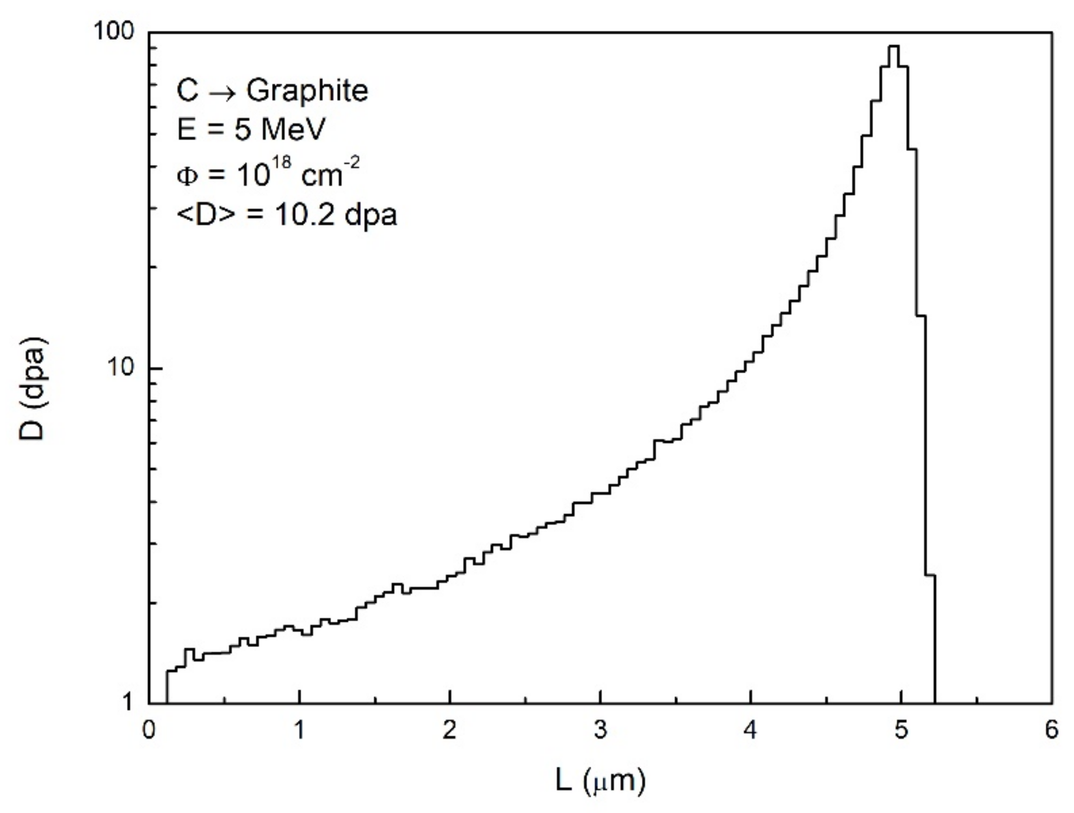
−2, respectively. Calculated in SRIM [20], the distribution of primary defects produced by 5 MeV 12C+ ions in the near-surface layer of graphite (ρ = 1.7 g/cm3) is given in Figure 1.
Maximal damage ~90 dpa is at a depth of about 5 microns corresponding to the range of 5 MeV C-ions in a carbon material of 1.7 g/cm3 density while average damage is 
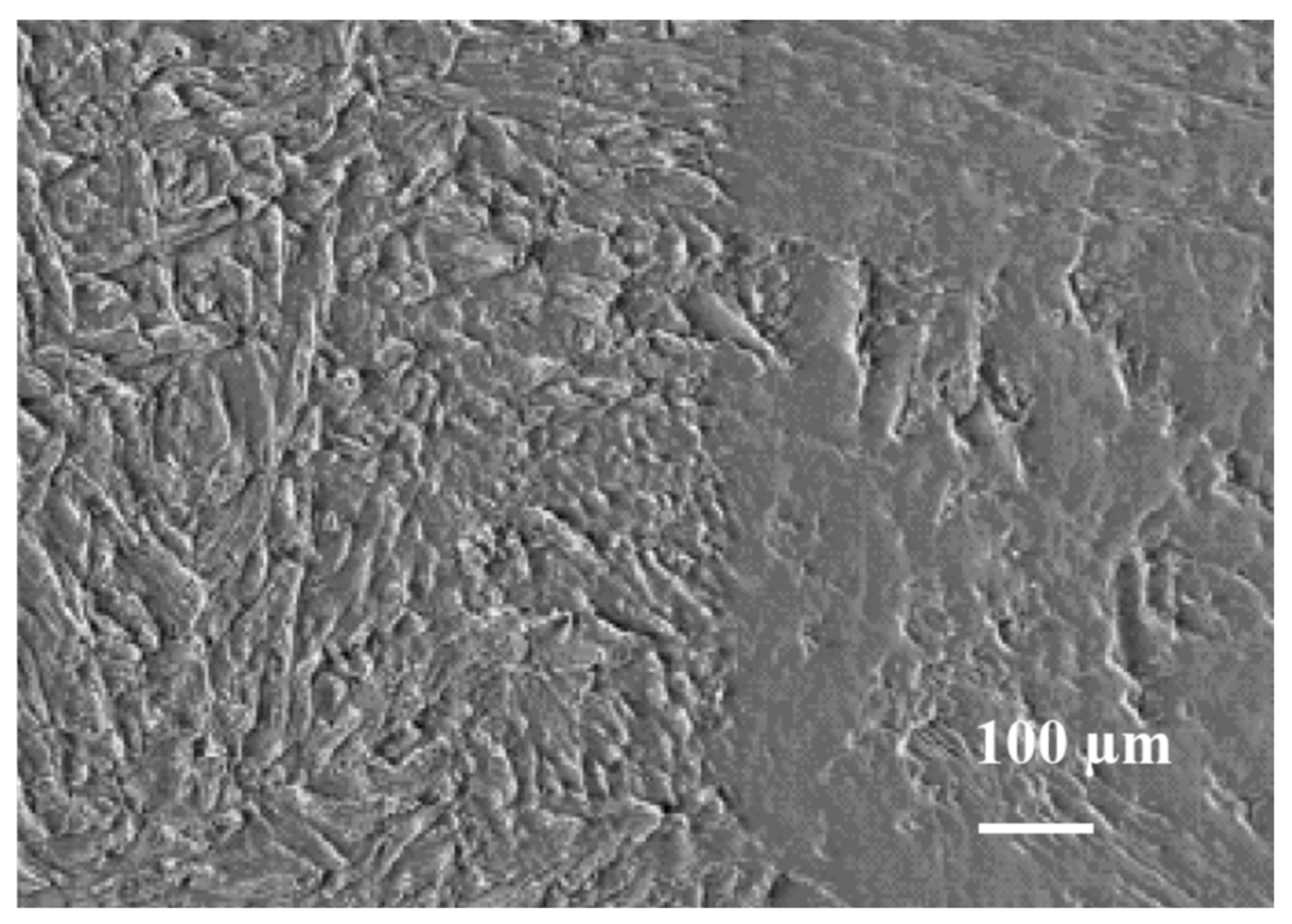
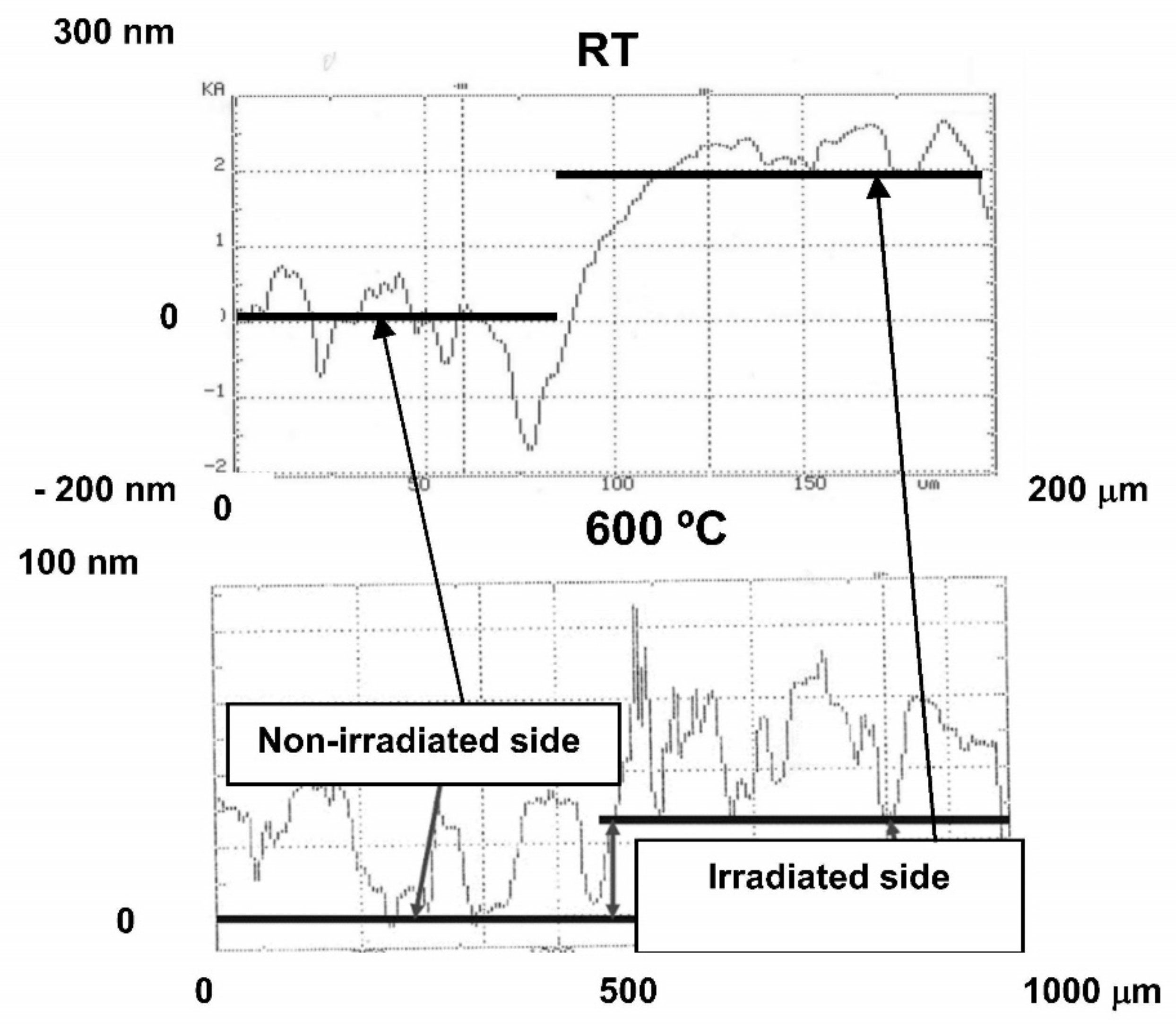
<D> = 10.2 dpa. The surface structure is modified under irradiation, though sputtering effect is not important. Modification of the surface structure of the SEP NB-31 sample is shown in Figure 2, where the boundary between irradiated and non-irradiated parts is apparent. Development of the surface is seen on the irradiated part of the surface.
A large radiation-induced deformation has been found on the carbon materials. This was clearly detected by profiling the surface around the boundary of the irradiated zone shown in 
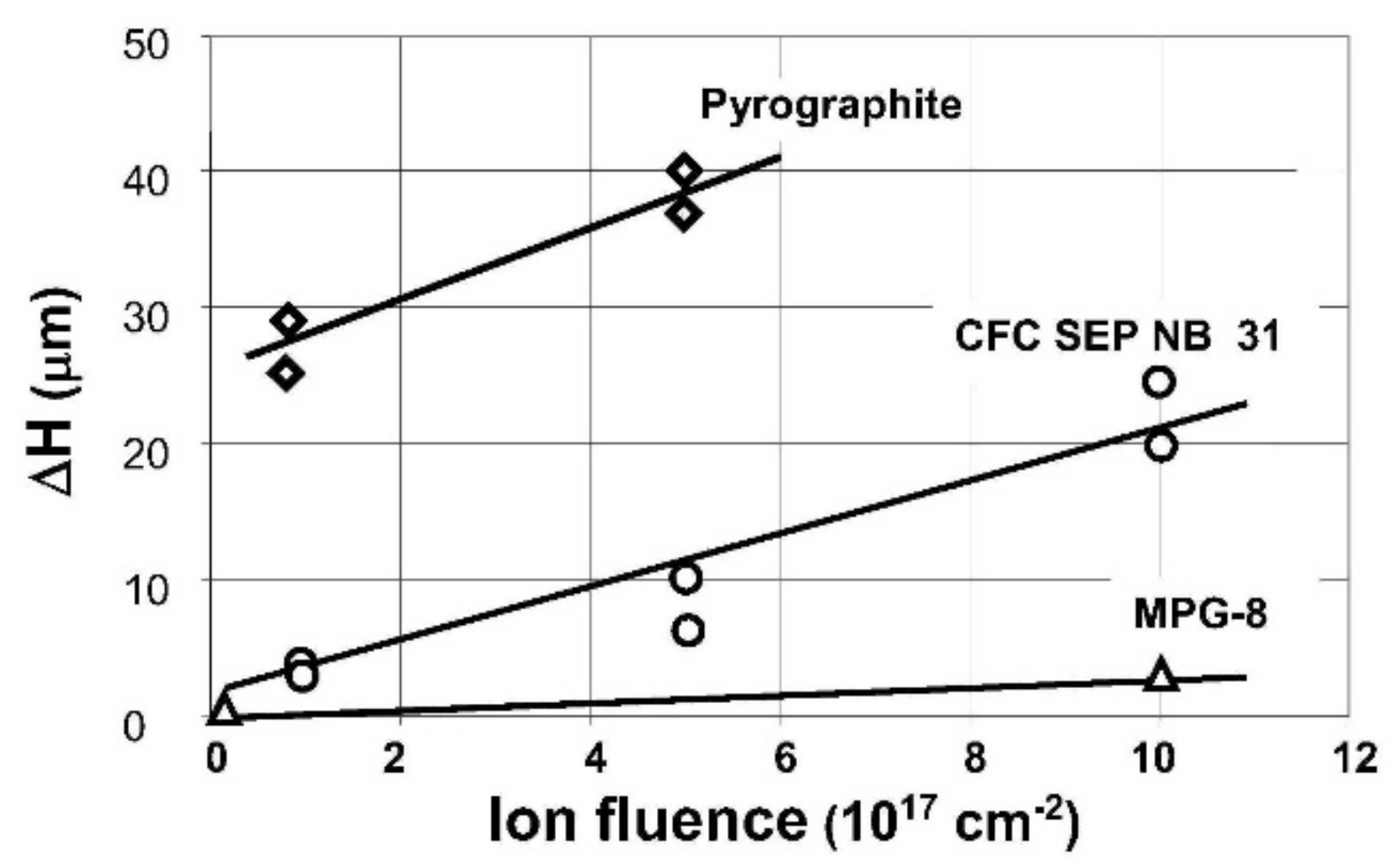
Figure 2. Considerable linear deformation measured with a profilometer was found on all ion irradiated graphites under study. The results of these measurements for all three types of materials are summarized in Figure 3 as a function of irradiation dose. The MPG-8 was found as the most radiation-resistant having minimal deformation in our case while the composite SEP NB-31 has shown large deformation: ΔH = 20 μm on 10 dpa sample (1018 cm−2). The deformation of the 10 dpa pyrographite sample surpassed the profilometer limit of 160 μm.
Thus, the studied graphites exhibited a great swelling effect after irradiation which was very large as compared with the damaged surface layer (~5 μm ion range). Besides the damage induced by fast ions, those materials undergo sputtering. Surface modification due to these effects was detected on all materials (see Figure 2). Splitting of the damage layer was also observed on pyrographite. Cracks were found on 5 and 10 dpa MPG-8.
The irradiated graphite samples were then exposed to the steady-state deuterium plasma on the LENTA plasma simulator. Exposure parameters were as follows: D-ion current 10 mA/cm
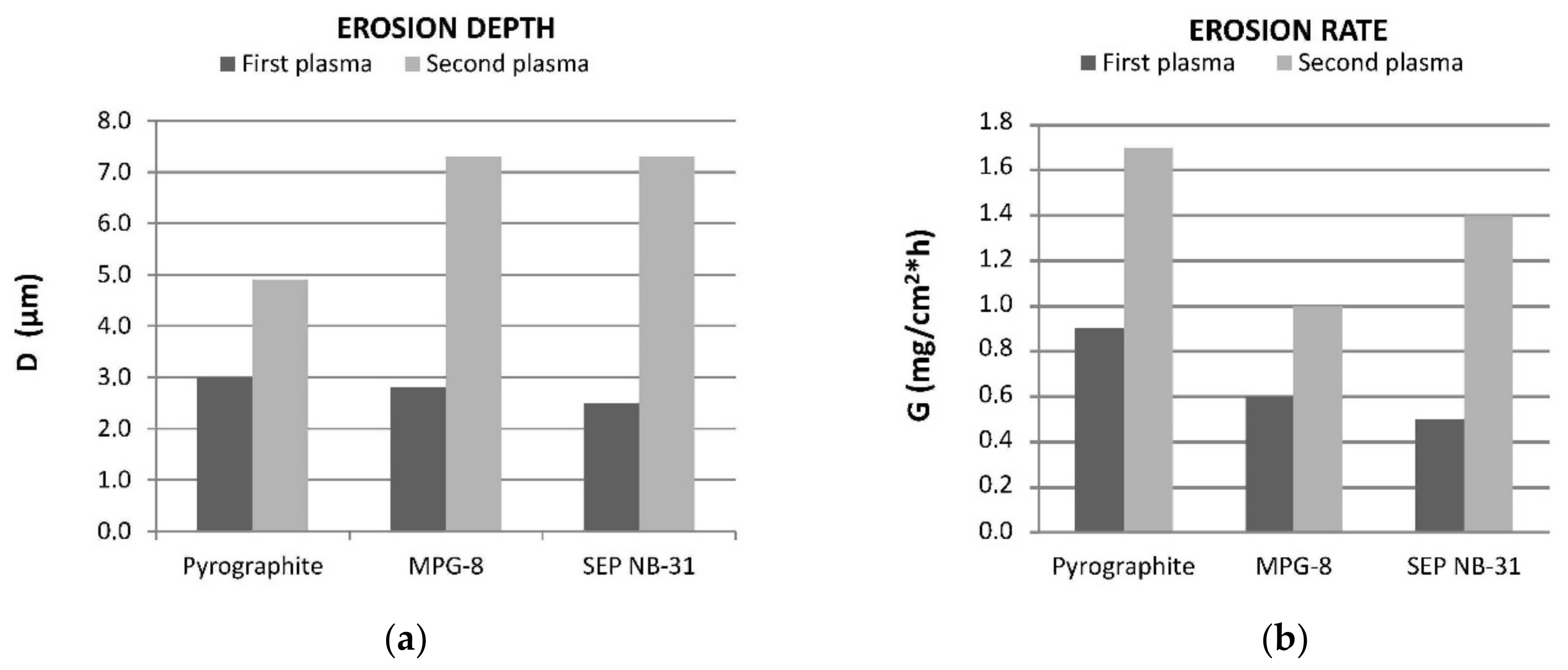
2, ion energy 100 eV (negative bias), sample temperature during plasma operation ≤40 °C. The carbon materials were processed in the plasma in two exposures 1 h each. The layer of about a half-fast ion penetration depth was eroded during the first step (about 2–3 µm), and the layer of the maximal radiation damage was eroded in the second plasma exposure (~3–7 µm) [21]. Weight loss due to the plasma bombardment was measured after each plasma exposure. The result of double successive plasma exposure of carbon materials is illustrated in Figure 4. Shown are the erosion depth and erosion rate of the three graphites under study after the first and after the second plasma runs. All materials exhibit increase in erosion rate in the second plasma exposure corresponding to the layer of maximal defect density involved in the erosion. This evidently shows the increase of erosion rate for higher irradiation damage levels of the investigated materials.
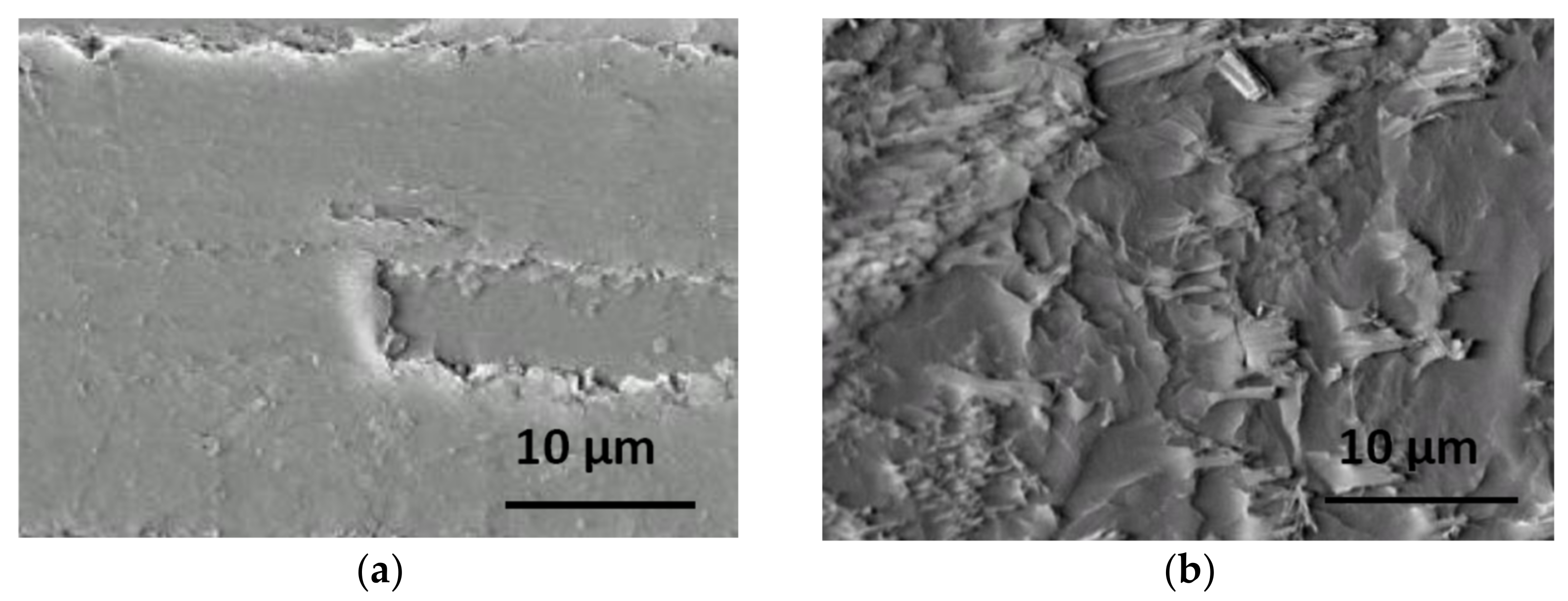
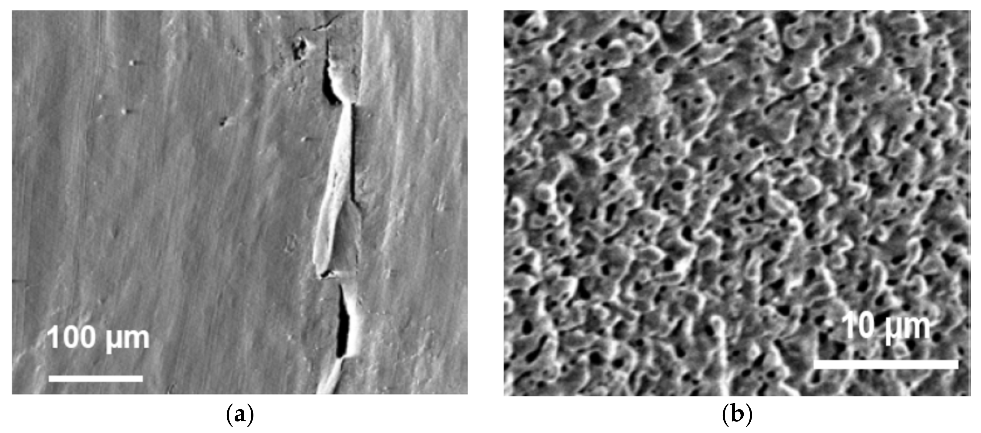
Changes in the surface microstructure were observed after each plasma exposure. An example of the SEP NB-31 surface irradiated to 10 dpa after plasma bombardment is shown in Figure 5b.
The adopted experimental procedure allows for the highly inhomogeneous distribution of the radiation defects in carbon materials thus enabling to get experimental data on erosion yield for different damage levels. Erosion yield was evaluated taking into account deuterium ion current to the surface. 
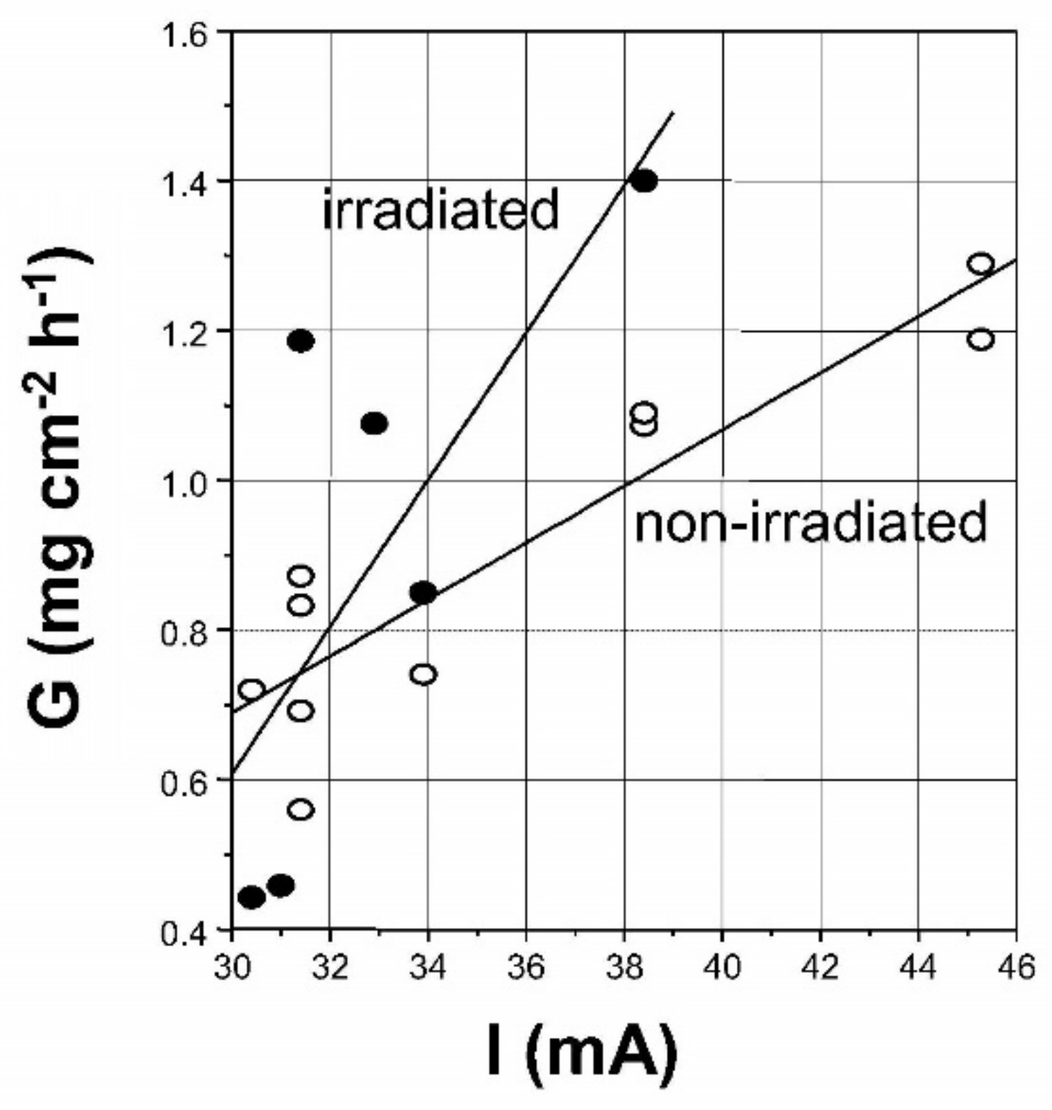
Figure 6 shows the erosion rate of the SEP NB-31 in D-plasma as a function of plasma current to the sample irradiated with high-energy ions and to the non-irradiated one. Erosion yield Y was deduced from these measurements as the slope of the curves plotted on the graph. Though scattered (for CFC), the result gives evidence of the higher erosion rate for the irradiated material. The enhancement factor of the erosion yield is given by the appropriate ratio of Y values for irradiated to non-irradiated materials as YSEP irrad/YSEP = 2.6 ± 0.6 for SEP NB-31 and even larger Ypyro irrad/Ypyro = 4.8 ± 0.4 for pyrographite while the minimal value YMPG irrad/YMPG = 1.6 ± 0.4 was found for MPG-8 [21].
Changes in the surface took place on the CFC materials. The formation of holes, whiskers, and cones was seen on the SEP and MPG samples. Our observations lead us to the conclusion that the radiation damage has a strong influence on the erosion in plasma of carbon plasma-facing materials increasing with higher damage levels. The effect is supposed to be determined by the radiation damage accumulated in the lattice that results in the material microstructure changing from dense to more friable (loss of regular structure).

4. Tungsten

Tungsten is the most actively studied material for usage in contact with plasma [22,23,24]. We have studied polycrystalline tungsten W 99.95 wt.% (Russian grade) as well as PLANSEE and POLEMA grades offered for ITER divertor armor. Tungsten samples were irradiated by different ion species: by 4He2+ at 3.5–4.5 MeV, by carbon ions 12C3+ at 10 MeV and by nitrogen ions 14N3+ at 28 MeV [16,17,18,19].

4.1. Tungsten Irradiated with Helium and Carbon Ions

4He2+ at 3.5–4.5 MeV irradiation was investigated as similar to fusion alpha particles at 3.5 MeV from DT reaction. W samples have been subjected to ion beam irradiation to reach fluence on the surface from 1017 cm−2 to 1019 cm−2. Defects produced in this way are distributed in the surface layer of about 6 μm in accordance with the 4He2+ range in tungsten. The results of He-irradiated tungsten (microstructure modification, swelling effect) have been reported elsewhere [16,17,18]. Helium porosity formation in the damaged layer was found at high helium fluences of 3 × 1018 cm−2–1019 cm−2. The presence of helium-filled micron-size pores and cavities would have a major influence on hydrogen penetration and retention in the material after exposure to deuterium plasma. The swelling effect was also detected by damaged tungsten surface profile measurements at 2–3%.
Another case of irradiation, namely, by 12C3+ has been investigated, which would help to distinguish effects of the accumulated He and of the damage itself on hydrogen retention in damaged tungsten [18]. Tungsten samples were irradiated with carbon ions 12C3+ accelerated to 10 MeV, the total ion fluence reaching (1–2) × 1017 cm−2. Ion energy and the total fluence value were chosen so that the resulting damage expressed in dpa was similar to that for He-ion irradiations. Figure 7 shows distributions of primary defects in tungsten produced by 4He2+ at 4 MeV and by 12C3+ at 10 MeV (SRIM calculations) in 3–7 µm layer. The concentration of the implanted ions is also presented.
Temperature as an important parameter for the research of a damaged material was also taken into account. Irradiations of tungsten by carbon ions were made at different temperatures, namely, at room temperature (RT) and at 600 °C. Figure 8 shows the damaged structure of tungsten irradiated with C ions at 600 °C taken by the TEM technique. Numerous vacancy pores and dislocation loops are presented in figure.
Linear deformations have been found on C-irradiated tungsten by surface topography observations. The result of the surface profile measurements is shown in Figure 9. The boundary of the irradiated area was studied for two temperatures of the material during irradiations—room temperature and 600 °C. The step corresponding to the swelling effect is clearly visible on the surface for both cases. The elevated part is on the irradiated area side. The swelling was much higher for the lower temperature irradiation. The measurement was made with necessary statistics in the high temperature case.
The irradiated tungsten samples were exposed to deuterium plasma. Experiments were carried out in erosion conditions in sequential order to study changes in the damaged layer and their consistency with the level of damage considering defect distributions (see Figure 7). The plasma exposure parameters were chosen so that a dynamic erosion condition was realized, and a notable sputtering of the material took place. Ion energy 250 eV exceeded the sputtering threshold at fluence Φ = 1021–1022 cm−2. Surface erosion, changes in the microstructure of the surface, and damaged layer were examined for these conditions (weight loss, SEM technique).
Figure 10 shows the surface and the damaged layer of the sample irradiated to 90 dpa in average for the case of maximal fast ion fluence He2+ (Φmax = 1019 cm−2, Φav = 3·1018 cm−2, E = 3–4 MeV) followed by plasma exposure with an erosion of 2 microns as a result. Cavities are displayed presumably filled with helium after irradiation.
An example of surface structure modifications of the He-irradiated sample, after plasma sequential exposures, is presented in Figure 11 where the surface has been changed from initially smooth to porous at higher plasma fluence (and higher damage).
The fracture of C-irradiated tungsten is shown for comparison in Figure 12 as registered after deuterium plasma: the surface layer 1 micron thick was sputtered by plasma bombardment. Considerable changes of microstructure by fast C ions in the layer of about 4 µm (the range of a carbon ion in tungsten) are clearly seen in figure.
C-irradiated samples have not shown spectacular changes of the surface structure after plasma as He-irradiated samples. SEM photos of C-irradiated tungsten after deuterium plasma are presented in Figure 13. The two pictures correspond to the close levels of primary defects (5–6 dpa) but to different temperatures of the material during irradiation and plasma exposure—room temperature and 500 °C, the difference between these two cases being though not significant but quite visible.
The erosion rate of tungsten was measured by weight loss in all plasma experiments. It was around 0.5–0.8 mg/cm2h in all cases. Erosion yield for D-plasma ions at an energy of 250 eV in the chosen conditions was Yd-w ≅ (2–4) × 10−3. No distinct influence of displacement damage on erosion rate has been found thus far. No correlation of the yield values has also been found with the damage level for different doses for both He-irradiated and C-irradiated tungsten.
Deuterium retention was studied by measurements of deuterium concentration in damaged tungsten after exposure of the irradiated samples to deuterium plasma at different steps of erosion from initial surface to the termination of the damaged layer (about high-energy ion range). Elastic Recoil Detection Analysis (reaction D(4He,D)4He, the probing depth of 1.9 MeV He beam ~150 nm) was applied to make profiling of deuterium concentration in the near-surface layer. An important increase of the retained deuterium (by an order) has been found at a depth of the maximal damage for He-irradiated tungsten and a large amount of the implanted helium (10% at.) has been detected by nuclear backscattering in the layer 2–3 μm wide at a depth of 5–6 μm (He ion range) [16,17,18].
Deuterium retention on C-damaged tungsten exposed to deuterium plasma was analyzed in experiments conducted at different temperatures of the material. Profiles of the retained deuterium are shown in Figure 14 for two tungsten samples. About ten-fold reduction of deuterium uptake has been registered on the high temperature sample in comparison with the room temperature case (8.7 × 1016 cm−2 to 0.8 × 1016 cm−2). Both deuterium distributions have a maximum at about 20–30 nm in the layer between 10–140 nm.
Direct comparison of the deuterium retention for He and C pre-irradiated samples were also performed. The ERDA results for four tungsten samples are presented in Figure 15 for room temperature. Two samples were irradiated with He ions and two others with C ions. The damage level at the surface was nearly the same (1–2 dpa) at the moment of the measurement (at the corresponding stage of the plasma erosion). The result shows that deuterium is concentrated around 20–40 nm (maximum) in a depth of 60 nm in all cases with a total amount of the detected deuterium (1.65–1.85) × 1016 cm−2.

4.2. Tungsten Irradiated with Nitrogen Ions

Irradiation by 14N3+ ions was explored on PLANSEE and POLEMA tungsten samples suggested for application in the ITER reactor [19]. Numerical calculations were performed to find out irradiation fluence needed to obtain damage comparable with those already obtained in He and C cases at fluence 1017 cm−2. Figure 16, Figure 17 and Figure 18 present primary defects concentrations in the surface layer along the ion penetration depth for three ion species. Figure 16 shows the result of tungsten irradiation with helium ions at 5 MeV to fluence 1017 cm−2. The corresponding data for carbon ions at 30 MeV is given in Figure 17. The calculation for nitrogen irradiation was made with the data given in Figure 18: ions 14N3+, energy 30 MeV, fluence 1017 cm−2. This choice gives average irradiation damage <DN> = 1.5 dpa in a layer of 8 μm which is close to <DC> = 0.9 dpa for carbon ions.
The surface microstructure of tungsten samples after irradiation by nitrogen ions had no spectacular changes, as was shown by SEM analysis. Given in Figure 19 is the surface of PLANSEE sample at the initial state and after irradiation by 14N3+ beam at 28 MeV to fluence 1017 cm−2.
The surface of the irradiated tungsten was also examined with a profilometer, and a significant swelling effect was detected as the result of radiation defects accumulated in the layer of 8 µm. The example of the surface profile registered around the boundary of the irradiated region is shown in Figure 20. The measured elevation values were from 600 Å to 1800 Å for the irradiated PLANSEE samples under study. Taking into account the depth of the damaged layer one may evaluate the swelling effect from 1% to 2.5%. Similar measurements were made on the POLEMA tungsten samples irradiated in the same conditions. The registered elevation step was 2200–2350 Å in this case. This corresponds to the swelling effect of 2.7–2.9% for the investigated material.
Both irradiated and non-irradiated samples were exposed to plasma. The samples were placed in contact with deuterium plasma generated by electron beam (4 kV, 1.3 A) at Ne = (2–3) × 1012 cm−3, Te = 2–5 eV. Plasma ion fluence FD reached during each plasma run was > 1021 cm−2; plasma flux on the surface was j = 2 × 1017 cm−2s−1. The energy of the incidents ions on the surface (bias) was 250 eV. The temperature of the samples was maintained at T = (50–80) °C by cooling. Examples of the plasma exposure parameters and the measured values of erosion rate and erosion yield are summarized in Table 1 for two samples of POLEMA and PLANSEE tungsten.
The erosion yield obtained in this experimental series was (4.1–4.7) × 10−3, and the numbers do not differ too much for the two studied materials. Similar Yw values were also on non-irradiated materials, and this does not reveal any relation of the erosion yield to the defect structure of the surface layer taking into account experimental errors.
SEM analysis of the surface was made at every stage of the experiments—after irradiation with high energy nitrogen ions and after plasma exposure. It was shown that fast ions irradiations did not result in visible changes of the surface structure. On the other hand, the surface exhibits strong transformations after exposure of the materials to deuterium plasma having extensive erosion (ex. 3 µm shown in Table 1). This effect is due to the changes in the crystal structure, and these are the development of intergranular boundaries where deep caverns appear bound to them. These features are clearly seen in Figure 21, presenting the surface of the pre-irradiated PLANSEE sample after plasma exposure.

5. Silicon Carbide (SiC)

Silicon carbide was included in the experimental study as a low-activated material. Experiments have been made aiming for the production of radiation-damaged material, and high energy protons were chosen for irradiation of SiC samples (1.5 mm thick) [19].
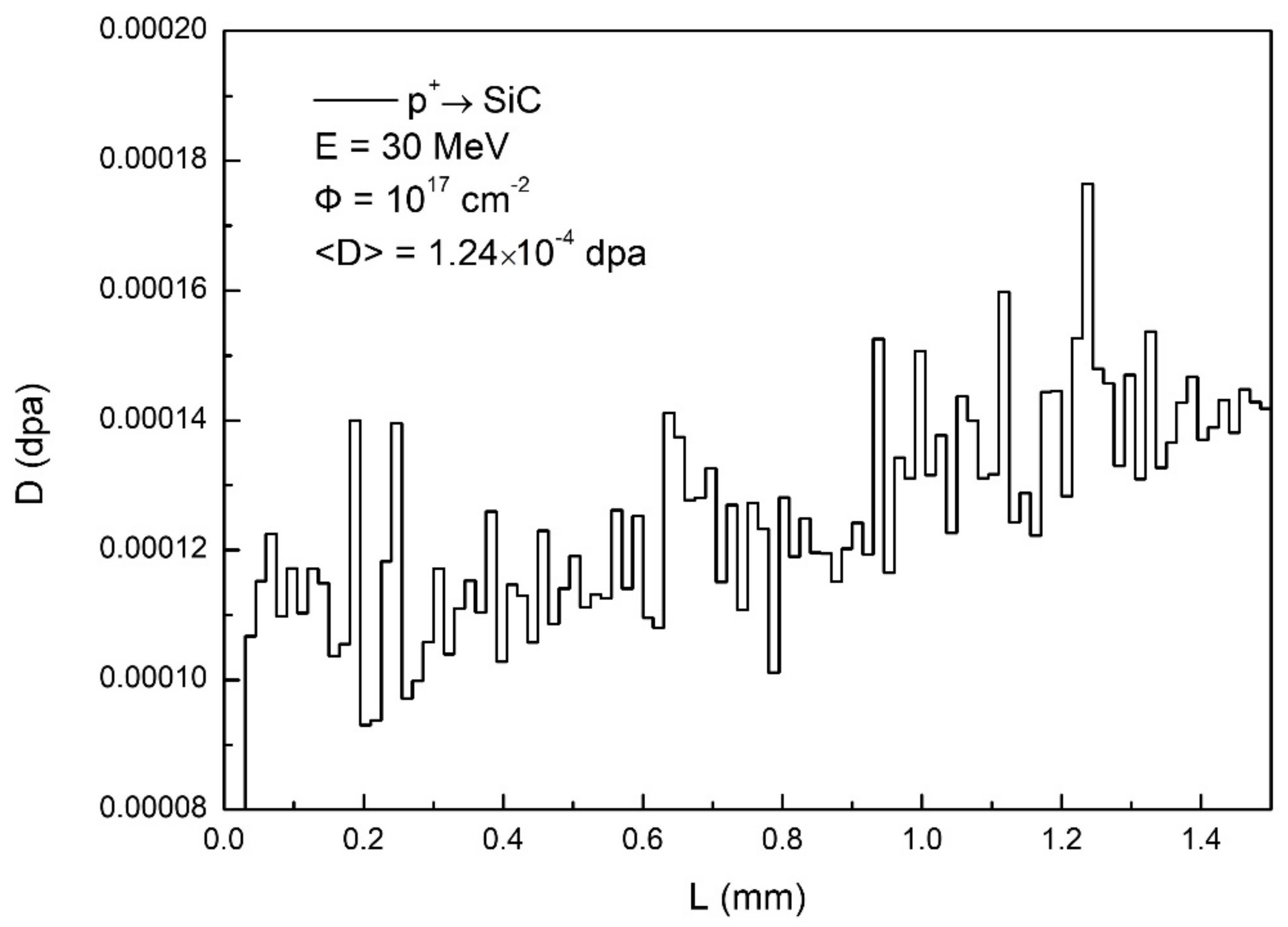
The calculation was performed in SRIM to obtain damage characteristics for the proton irradiated SiC material. Threshold energy for the defect production was 35 eV and 20 eV for silicon and carbon, correspondingly. The result given in Figure 22 is the primary defect concentrations in SiC for protons accelerated to 30 MeV for Φ = 1017 cm−2. These protons produce damage to the whole thickness of the samples (1.5 mm) at a level of 1.23 × 10⁻⁴ dpa on average.
SiC samples were pre-irradiated with protons with an energy of 32 MeV to fluence 1017 cm−2. Then the samples were exposed to deuterium plasma on the LENTA plasma simulator in the following conditions:
  • deuterium ion flux on the surface 1.2 × 1017 cm−2s−1;
  • incident ions energy 100 eV;
  • deuterium plasma fluence 0.4 × 1021 cm−2;
  • surface temperature < 100 °C (water cooled target).
The erosion depth of the plasma exposed material was 0.6–2 µm as measured by weight loss, and erosion yield was found to be at (1–2) × 10−2 that is consistent with experimental data on the sputtering of carbon and silicon by deuterium ions.
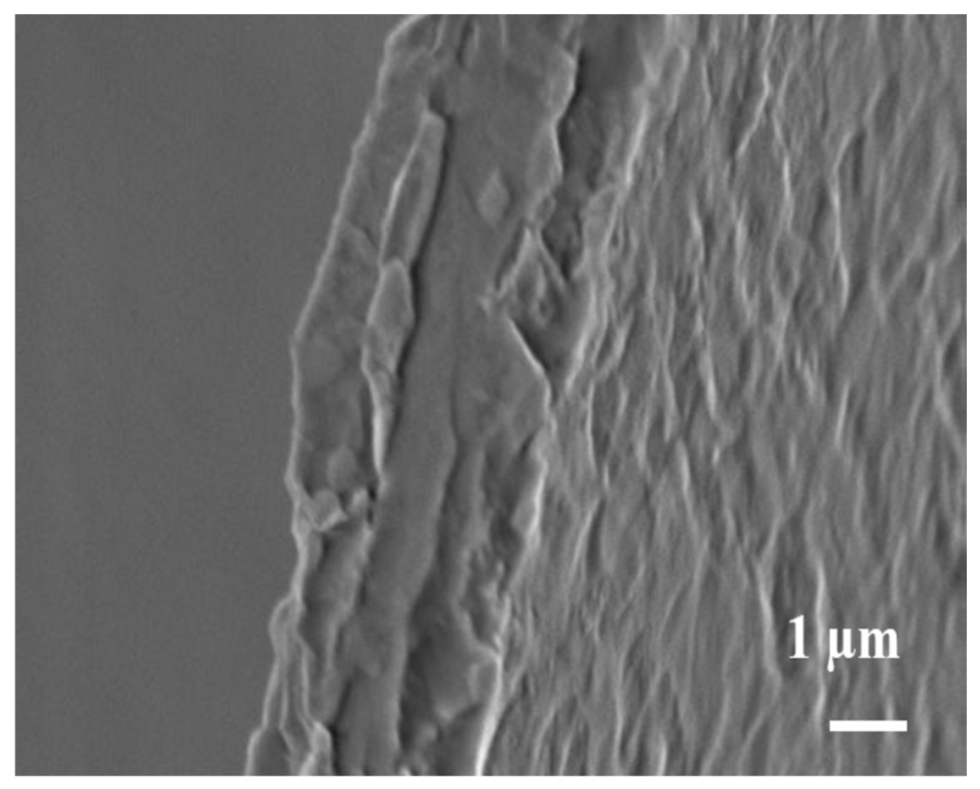
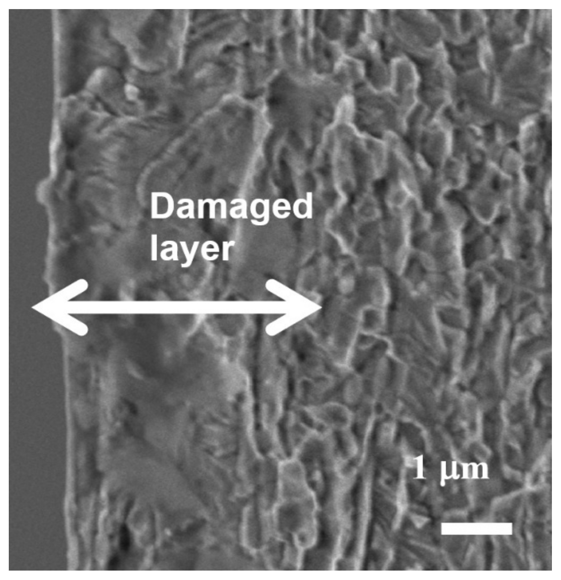
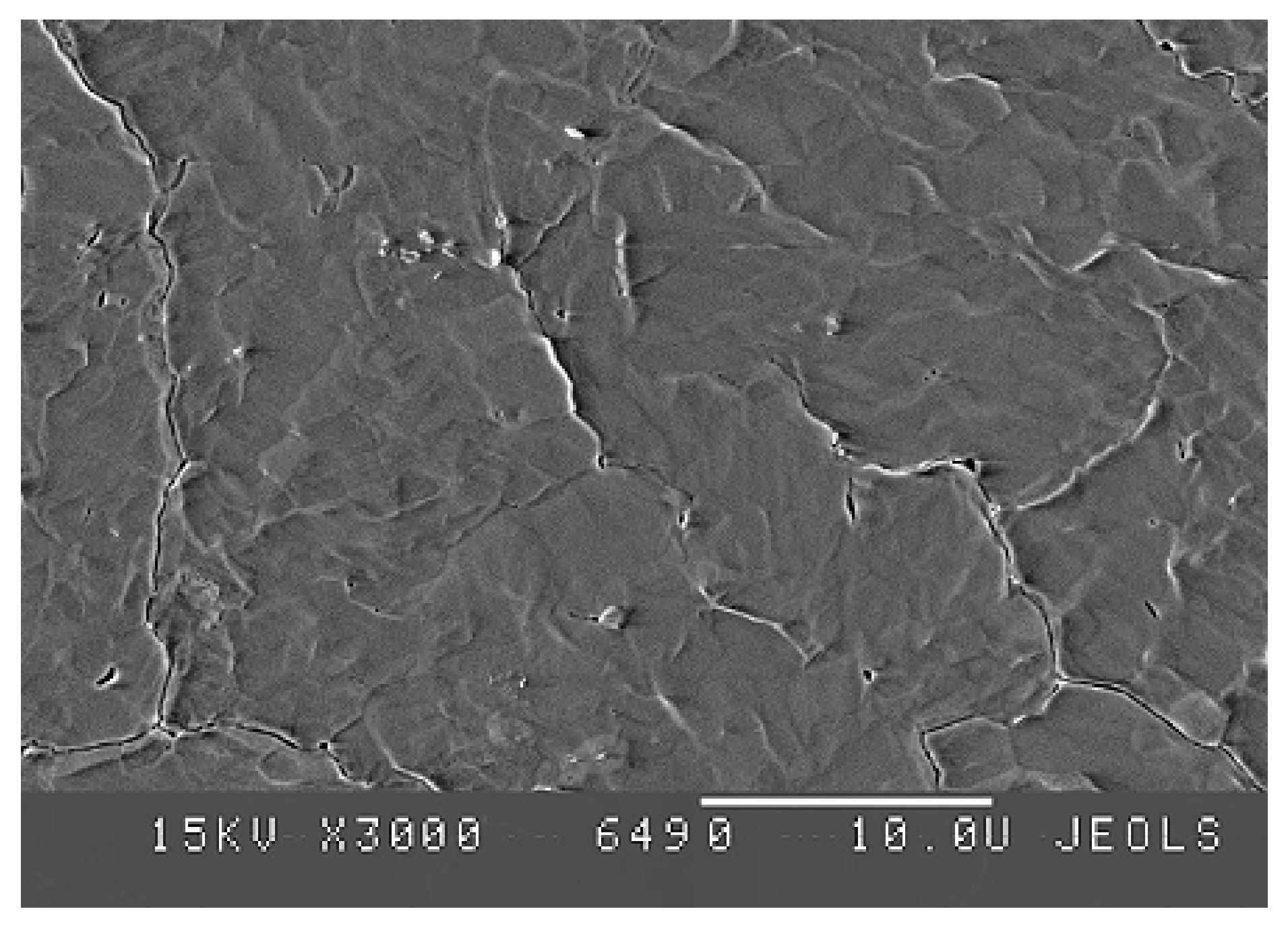
Surface structure was analyzed at different stages of the experiments by SEM and TEM microscopy. 
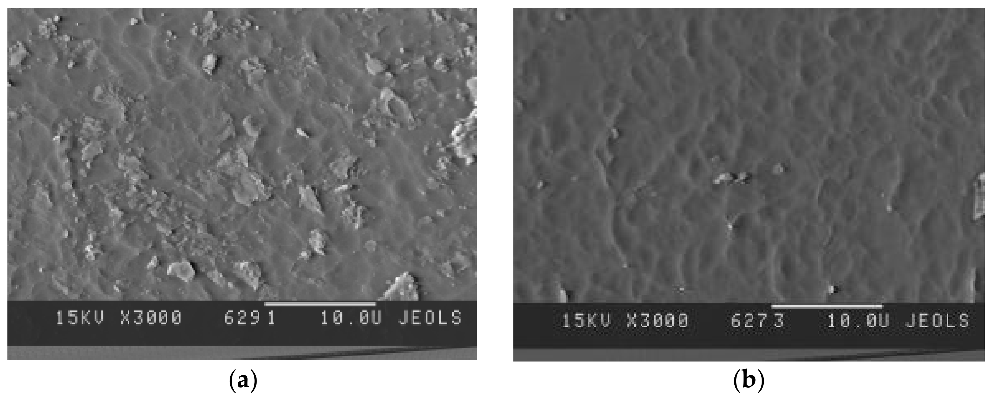
Figure 23 shows the initial state of the SiC surface. The result of the plasma exposure of the irradiated and of non-irradiated material is shown in Figure 24.
The analysis showed that the production of defects in the material by fast protons induces important changes in the surface structure at plasma erosion regime. They are manifested by the appearance of a large number of flaky elements that, in turn, may enhance erosion. The erosion process is evolving on the background of the mosaic structure which is clearly revealed on the wavy surface of the non-irradiated material (Figure 24).

6. Discussion and Conclusions

The experimental investigation of plasma-facing materials suggested for use in reactors with DT fusion reaction is presented in this review. The major problem of the work was to obtain experimental data on the behavior and stability of the materials facing plasma under fast neutrons irradiation accompanied by the plasma bombardment. A complex method was applied based on surrogate ion irradiation to produce radiation damage in the materials and simulate neutron effect and exposure of the irradiated materials to D-plasma simulating the conditions of tokamak-reactor. The research was conducted on the facilities of the NRC “Kurchatov institute”—the cyclotron U-150 providing accelerated ions up to 60 MeV and linear plasma divertor simulator LENTA.
Carbon-based materials, tungsten of different grades, and silicon carbide were studied. Ions of 4He2+, 12C3+, 14N3+ and H+ (protons) accelerated to 3.5–10 MeV depending on a particular case were taken for irradiations.
Radiation damage reached in carbon materials was 1–10 dpa on average over the layer of ion range, which was ~5 μm for CFC SEP NB-31, MPG-8 low-pore graphite, and pyrographite quasi-single crystal. The studied graphites exhibited a large linear deformation after irradiation, and that was the highest for pyrographite, while the MPG-8 has shown to be the most resistant to radiation with minimal deformation. A large deformation was also measured on the 10 dpa sample SEP NB-31 as ΔH = 20 μm compared with 5 μm ion range (C ions, 1018 cm−2). Linear growth of the deformation with ion dose was clearly registered for these carbon materials. The damages accumulated in the graphites along with sputtering of the irradiated materials during exposure in plasma brought to the surface modification observed by SEM analysis. Surface modification due to these effects was detected on all carbon materials as the splitting of the damaged layer on pyrographite, cracks on 5 and 10 dpa MPG-8. Holes, whiskers, and cones were also seen on the SEP and MPG surface. Measurement of the erosion rate has shown that it was higher for the irradiated carbon materials than for non-irradiated ones with an increasing rate for the higher irradiation damage level. This was attributed to the enhancement of the chemical erosion which is typical in general for carbon materials in deuterium plasma. In this case, the damaged layer was sputtered due to a significant energy deposition during irradiation.
The irradiation conditions by different ion species for tungsten samples were chosen to obtain a similarly close defect production pattern in the damaged layer and to provide a possibility for the comparative analysis of the results. The plasma impact on the damaged tungsten was studied in the dynamic condition of the sputtered surface progress. This method revealed that relation of the damage level being highly inhomogeneous in the 3–6 µm layer with tungsten structure and deuterium retention. The obtained results showed the formation of different structures of the material after high-energy ion irradiations for two ion species used for damage production—He and C. The damaged tungsten structure has shown large changes; the formation of bubbles and cavities has been found. The damage was strongly manifested in changes of the surface microstructure during exposure to the plasma—cracking, blistering, delaminating (in He-irradiated W). Helium is supposed to be accumulated in the pores observed in the damaged layer of several micron sizes and cavities, and they may develop under plasma bombardment and may have an influence on the changes in the structure with helium release to the material surface.
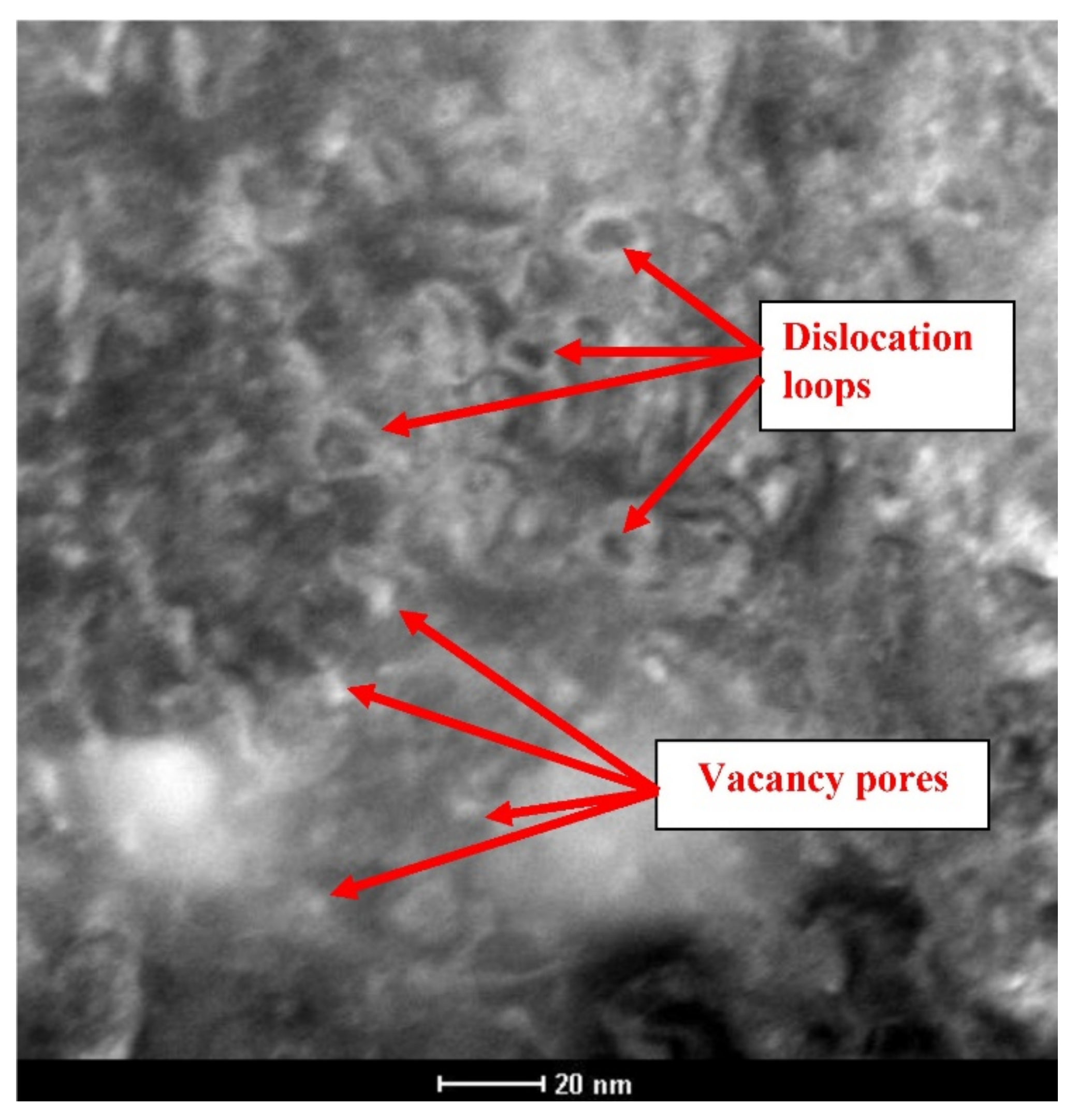
The swelling effect has been clearly detected on tungsten at 1.5–5% by the linear deformation control. Also, TEM analysis has shown the development of loop and vacancy pore systems in the material damaged by energetic ions.
A lot of measurements of erosion rate and erosion yield have been made in our experiments both for He and C cases. Erosion yield was quantified as Yd-w ≅ (2–4) × 10−3 both for He and C and cases for different damage levels of the layers facing the plasma, and this was about the same as for undamaged tungsten. Thus, no correlation was found with the damage level or irradiation method, and no clear damage effect on tungsten erosion rate was found thus far in contrast with erosion enhancement found earlier on damaged graphite materials [15]. This might be attributed to different erosion mechanisms of tungsten and carbon materials—chemical erosion activated by damage and pure physical sputtering of tungsten.
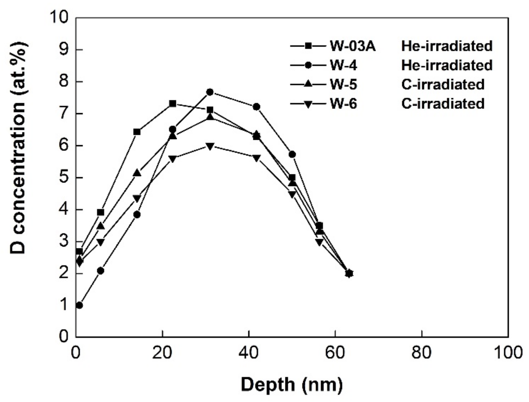
The ERD method used in the work supplied data on D-concentration in the near-surface layer down to 100–150 nm deep. The results on hydrogen isotope retention described in Section 4 show that distributions of deuterium and its quantities in the damaged near-surface layer may not be very different for He and C cases and, in contrast, they may be very similar for the two methods of damage production in tungsten (He and C) for the equivalent damage levels with 6–8 at.% maximum in the layer of about 60–100 nm. The observed D-distributions may be explained by the generation of the traps which might control the diffusion of deuterium into the bulk, and they might dominate deuterium solution and simple bulk diffusion. The similarity of the profiles for maximal and total retention (over measured layer) observed for C and He irradiations for close damage levels (2–3 dpa) support this consideration. Other effects such as the trapped-induced Gorsky effect [25] should also be taken into account for describing the observed D-profiles in the near-surface layers.
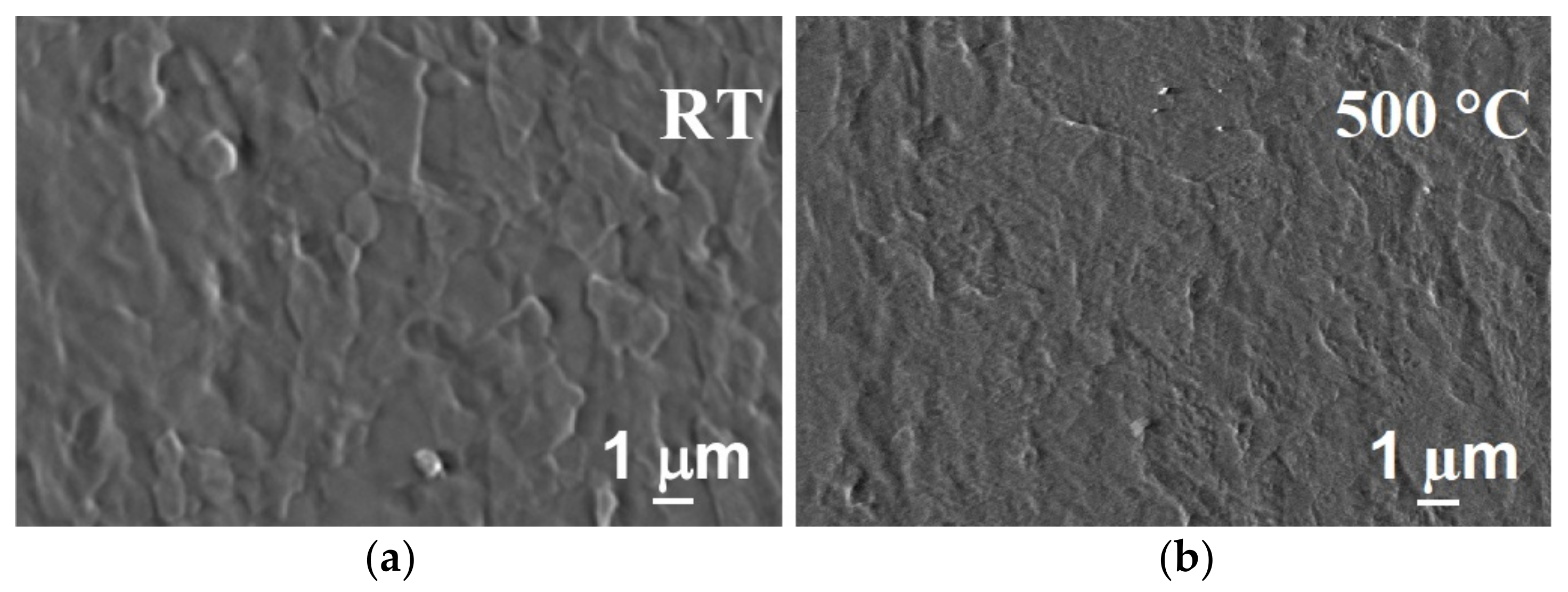
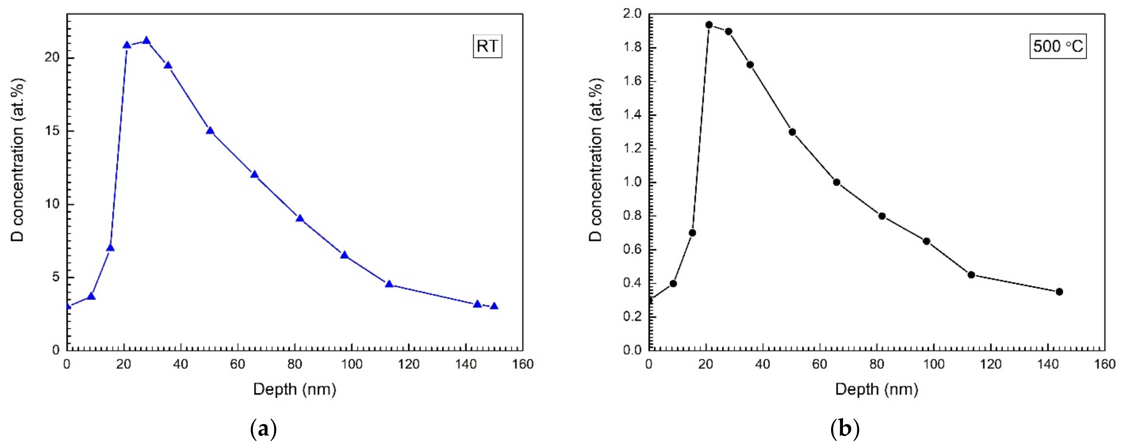
The damage produced by C ions at room temperature resulted in a large deuterium accumulation (20 at.%) while the experiments conducted at 500 °C showed low retention, which was at the same time very close to the retention values detected for the undamaged material. With all features of ERD analysis taken into account (small depth), this result appears to be rather significant for the investigations of possible tritium inventory in tungsten as showing the necessity to explore the effect at increased temperatures.
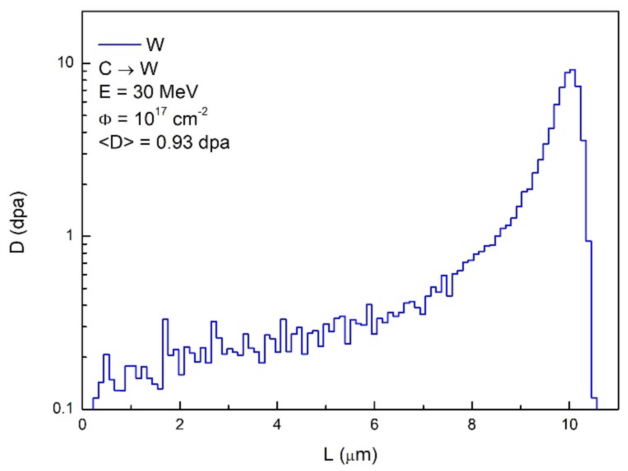
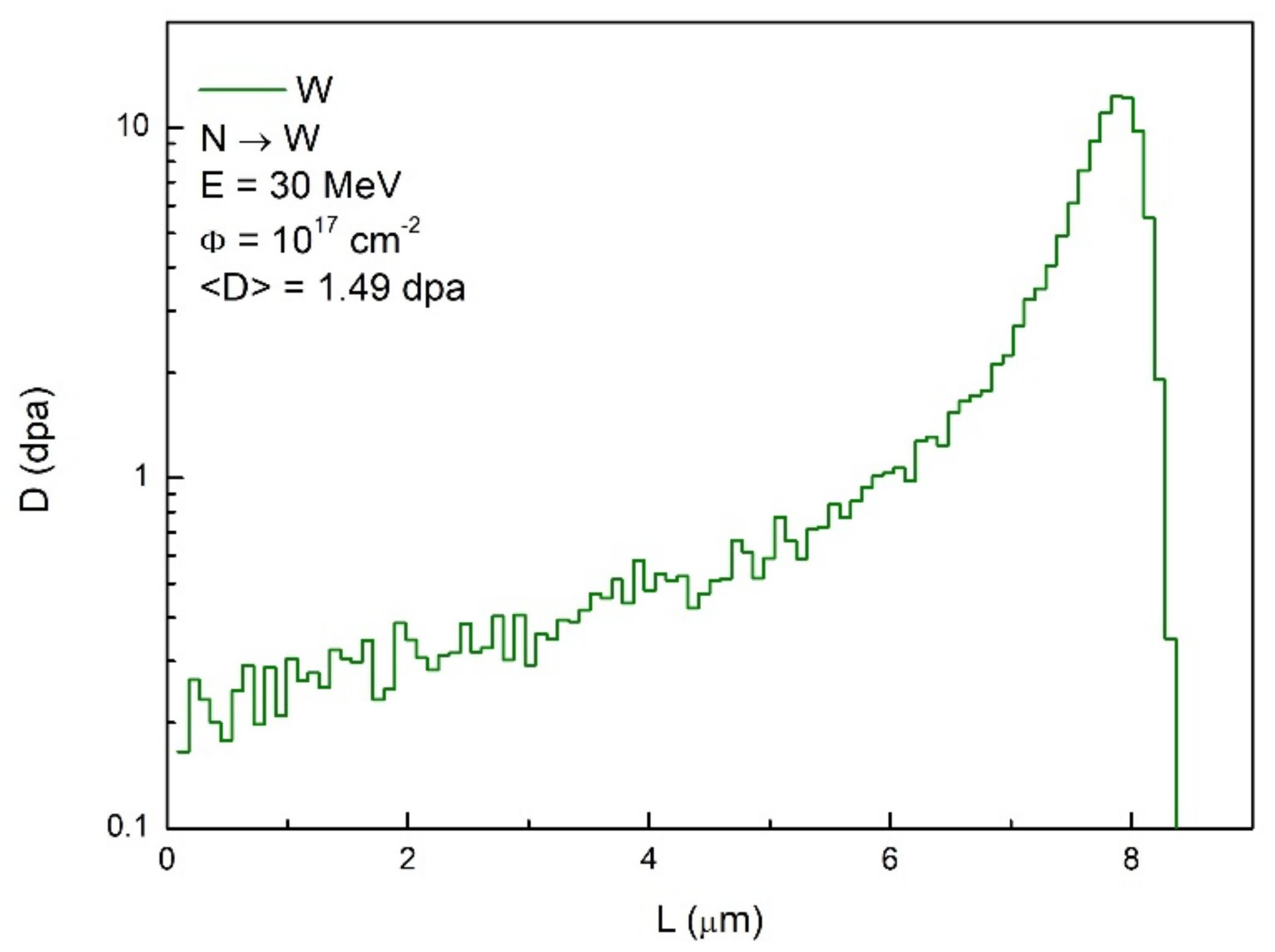
The irradiations of tungsten samples were also made with 14N3+ ions. As calculation analysis has shown the damaged layer is formed to a depth of ~8 µm for 30 MeV 14N3+ ions. Two tungsten grades PLANSEE (Austria) and POLEMA (RF) were subjected to those irradiations. The samples damaged up to 10 dpa at the ions stopping range were obtained. As a result of the irradiation, important linear deformation has been found by profiling measurements on the irradiated surface. Evaluation of the swelling effect gave 2.5% for PLANSEE and 2.9% for POLEMA tungsten. The erosion yield of these two materials in deuterium plasma was evaluated at Yw = (4.1–4.7) × 10−3. Changes in the surface morphology specific to this method of irradiation were observed as the development of the intergranular boundaries and formation of holes.
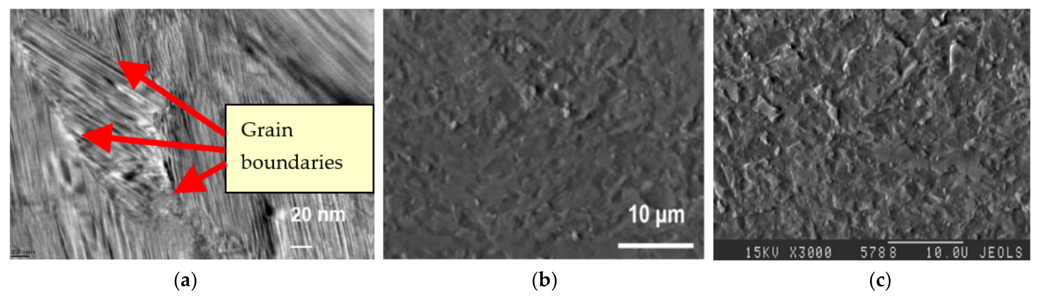
Samples of silicon carbide SiC were also studied in deuterium plasma after irradiation by high-energy protons. The loss of a regular structure was found on the surface after irradiation with 30 MeV protons. Formation of the flaky surface structures would facilitate erosion of the material in the plasma.
In general, an increased role of grain boundaries in the accumulation and diffusion of the produced defects is revealed in all the described experiments, and this fact becomes evident after plasma exposures following the defect production by high energy particles. Changes in the surface took place in the materials as a result of the accumulated energy in the damaged layer, which loses the regular structure of the solid determined by the symmetry properties. The effect is due to the radiation damage of lattice that results in the material microstructure change from dense to looser. This also leads to changes of physical properties important for the application of the considered materials as of plasma-facing armor (thermal conductivity, erosion rate, etc.).
Finally, we may conclude that the method applied in this work has proven to be efficient for the simulation of the neutron effect in materials being developed for fusion reactors. Using the surrogate fast ion irradiations in complex with the study of the irradiated materials in the plasma matching the tokamak SOL conditions enables getting direct experimental data extremely needed at the stage of the development of future fusion reactors facilitating the choice of materials facing plasma and providing a basis for the evaluations of their service life under high neutron and plasma impact.

Author Contributions

Conceptualization, B.I.K. and E.V.S.; methodology, B.I.K.; software, E.V.S.; validation, B.I.K., V.S.K. and E.V.S.; formal analysis, B.I.K.; investigation, B.I.K. and E.V.S.; resources, B.I.K. and E.V.S.; data curation, B.I.K.; writing—original draft preparation, B.I.K.; writing—review and editing, B.I.K. and E.V.S.; visualization, E.V.S.; supervision, V.S.K.; project administration, V.S.K.; funding acquisition, B.I.K. and V.S.K. All authors have read and agreed to the published version of the manuscript.

Funding

The work was supported by Russian Foundation for Basic Research, projects No. 13-08-00692, 10-08-01170, 11-08-01093, 15-08-04409, 19-08-00994.

Informed Consent Statement

A lot of work in this study was done by A.I. Ryazanov, who recently passed away.

Conflicts of Interest

The authors declare no conflict of interest.

References

  1. Barabash, V.; Federici, G.; Linke, J.; Wu, C. Material/plasma surface interaction issues following neutron damage. J. Nucl. Mater. 2003, 313–316, 42–51. [Google Scholar] [CrossRef]
  2. Roth, J.; Schmid, K. Hydrogen in tungsten as plasma-facing material. Phys. Scr. 2011, T145. [Google Scholar] [CrossRef] [Green Version]
  3. Bolt, H.; Barabash, V.; Federici, G.; Linke, J.; Loarte, A.; Roth, J.; Sato, K. Plasma facing and high heat flux materials—Needs for ITER and beyond. J. Nucl. Mater. 2002, 307–311, 43–52. [Google Scholar] [CrossRef]
  4. Shimada, M.; Hara, M.; Otsuka, T.; Oya, Y.; Hatano, Y. Defect annealing and thermal desorption of deuterium in low dose HFIR neutron-irradiated tungsten. J. Nucl. Mater. 2015, 463, 1005–1008. [Google Scholar] [CrossRef] [Green Version]
  5. Sawan, M.E. Damage parameters of structural materials in fusion environment compared to fission reactor irradiation. Fusion Eng. Des. 2012, 87, 551–555. [Google Scholar] [CrossRef]
  6. Flerov, G.N.; Barashenkov, V.S. Practical applications of heavy ion beams. Sov. Phys. Uspekhi 1975, 17, 783–793. [Google Scholar] [CrossRef]
  7. Markina, E.; Mayer, M.; Elgeti (Lindig), S.; Schwarz-Selinger, T. Influence of MeV helium implantation on deuterium retention in self-ion implanted tungsten. Phys. Scr. 2014, T159, 14045. [Google Scholar] [CrossRef] [Green Version]
  8. Wampler, W.; Doerner, R. The influence of displacement damage on deuterium retention in tungsten exposed to plasma. Nucl. Fusion 2009, 49. [Google Scholar] [CrossRef]
  9. Cui, S.; Doerner, R.P.; Simmonds, M.J.; Xu, C.; Wang, Y.; Dechaumphai, E.; Fu, E.; Tynan, G.R.; Chen, R. Thermal conduc-tivity degradation and recovery in ion beam damaged tungsten at different temperature. J. Nucl. Mater. 2018, 511, 141–147. [Google Scholar] [CrossRef]
  10. Hatano, Y.; Shimada, M.; Alimov, V.; Shi, J.; Hara, M.; Nozaki, T.; Oya, Y.; Kobayashi, M.; Okuno, K.; Oda, T.; et al. Trapping of hydrogen isotopes in radiation defects formed in tungsten by neutron and ion irradiations. J. Nucl. Mater. 2013, 438, S114–S119. [Google Scholar] [CrossRef] [Green Version]
  11. Hatano, Y.; Toyama, T.; Lee, H.T.; Ueda, Y.; Oya, Y.; Yajima, M.; Ohno, N. Defect-hydrogen isotope interactions in neutron irradiated tungsten, and effects of alloying elements and crystal orientation on defect formation under surrogate irradiations. In Atomic and Plasma–Material Interaction Data for Fusion; International Atomic Energy Agency: Vienna, Austria, 2019; pp. 55–68. [Google Scholar]
  12. Deshpande, S.P.; Raole, P.M.; Maya, P.N.; Sharma, P.; Attri, A.; Tyagi, A.K.; Kumar, R.; Vala, S.S.; Satyaprasad, A.; Mukherjee, S.; et al. Simulation of radiation damage and ion-irradiation experiments with tungsten. In Atomic and Plasma–Material Interaction Data for Fusion; International Atomic Energy Agency: Vienna, Austria, 2019; pp. 3–44. [Google Scholar]
  13. Gasparyan, Y.; Ogorodnikova, O.; Efimov, V.; Mednikov, A.; Marenkov, E.; Pisarev, A.; Markelj, S.; Čadež, I. Thermal desorption from self-damaged tungsten exposed to deuterium atoms. J. Nucl. Mater. 2015, 463, 1013–1016. [Google Scholar] [CrossRef]
  14. Li, X.; Xu, Y.; Zhang, Y.; Liu, S. Across-scale self-healing mechanisms for radiation damage in nano-crystal tungsten. In Atomic and Plasma–Material Interaction Data for Fusion; International Atomic Energy Agency: Vienna, Austria, 2019; pp. 81–126. [Google Scholar]
  15. Khripunov, B.; Brukhanov, A.; Chugunov, O.; Gureev, V.; Koidan, V.; Kornienko, S.; Kuteev, B.; Latushkin, S.; Muksunov, A.; Petrov, V.; et al. Evidence of radiation damage impact on material erosion in plasma environment. J. Nucl. Mater. 2009, 390–391, 921–924. [Google Scholar] [CrossRef]
  16. Koidan, V.; Khripunov, B.; Ryazanov, A.; Gureev, V.; Kornienko, S.; Latushkin, S.; Muksunov, A.; Petrov, V.; Semenov, E.; Stolyarova, V.; et al. Production of Radiation-Damaged Tungsten and its Study in High Flux Deuterium Plasma. In Proceedings of the 25th IAEA Fusion Energy Conference, St. Petersburg, Russia, 13–18 October 2014; Paper MPT/P7-37. Available online: https://www-pub.iaea.org/MTCD/Meetings/PDFplus/2014/cn221/cn221ProvisionalProgramme.pdf (accessed on 21 October 2021).
  17. Khripunov, B.I.; Koidan, V.S.; Ryazanov, A.I.; Gureev, V.M.; Kornienko, S.N.; Latushkin, S.T.; Muksunov, A.M.; Semenov, E.V.; Stolyarova, V.G.; Unezhev, V.N. Radiation-Damaged Tungsten: Production and Study in a Steady-State Plasma Flux. Phys. At. Nucl. 2018, 81, 1015–1023. [Google Scholar] [CrossRef]
  18. Khipunov, B.I.; Koidan, V.S.; Ryazanov, A.I. High-flux plasma effect on tungsten damaged by high-energy ions. In Atomic and Plasma–Material Interaction Data for Fusion; International Atomic Energy Agency: Vienna, Austria, 2019; pp. 69–80. [Google Scholar]
  19. Khripunov, B.I.; Koidan, V.S.; Ryazanov, A.I.; Gureev, V.M.; Latushkin, S.T.; Semenov, E.V.; Stolyarova, V.G. Impact of Deuterium Plasma Flux on Fusion Materials: Radiation Damage, Surface Modification, Erosion. Phys. At. Nucl. 2021, 84, 1–7. [Google Scholar]
  20. Ziegler, J.F.; Ziegler, M.; Biersack, J. SRIM—The stopping and range of ions in matter. Nucl. Instruments Methods Phys. Res. Sect. B: Beam Interact. Mater. At. 2010, 268, 1818–1823. [Google Scholar] [CrossRef] [Green Version]
  21. Ryazanov, A. Using of charge particle accelerators for investigation of physical mechanisms radiation resistance of fission and fusion structural materials. Probl. At. Sci. Technol. 2009, 4, 116–126. [Google Scholar]
  22. Rieth, M.; Dudarev, S.; de Vicente, S.G.; Aktaa, J.; Ahlgren, T.; Antusch, S.; Armstrong, D.; Balden, M.; Baluc, N.; Barthe, M.-F.; et al. Recent progress in research on tungsten materials for nuclear fusion applications in Europe. J. Nucl. Mater. 2013, 432, 482–500. [Google Scholar] [CrossRef] [Green Version]
  23. Shimada, M.; Hatano, Y.; Oya, Y.; Oda, T.; Hara, M.; Cao, G.; Kobayashi, M.; Sokolov, M.; Watanabe, H.; Tyburska-Püschel, B.; et al. Overview of the US–Japan collaborative investigation on hydrogen isotope retention in neutron-irradiated and ion-damaged tungsten. Fusion Eng. Des. 2012, 87, 1166–1170. [Google Scholar] [CrossRef] [Green Version]
  24. Wielunska, B.; Mayer, M.; Schwarz-Selinger, T.; Sand, A.E.; Jacob, W. Deuterium retention in tungsten irradiated by different ions. Nucl. Fusion 2020, 60, 096002. [Google Scholar] [CrossRef]
  25. Hu, A.; Hassanein, A. Modeling hydrogen isotope behavior in fusion plasma-facing components. J. Nucl. Mater. 2014, 446, 56–62. [Google Scholar] [CrossRef]
Figure 1. Primary radiation defects as a function of depth for a carbon material (ρ = 1.7 g/cm3) irradiated with 5 MeV C-ions to a dose of 1018 cm−2.
Symmetry 13 02081 g001
Figure 2. Border on the surface of the SEP NB-31 sample irradiated to <D> = 10 dpa: damaged area is to the left; the right part was shielded from the irradiation. The scale is 100 µm [21].
Symmetry 13 02081 g002
Figure 3. Linear deformation of carbon materials ΔH after irradiation with 5 MeV C-ions.
Symmetry 13 02081 g003
Figure 4. Erosion depth (a) and erosion rate (b) in double plasma experiment for 1 dpa samples of SEP NB-31, MPG-8 and pyrographite.
Symmetry 13 02081 g004
Figure 5. SEP NB-31 surface at initial state (a) and after irradiation with C ions to 10 dpa and plasma exposure (b) [15,21].
Symmetry 13 02081 g005
Figure 6. SEP NB-31 erosion rate vs. ion current in D-plasma [15,21].
Symmetry 13 02081 g006
Figure 7. Distributions of primary defects (dpa) and implanted ion concentrations (at.%) in tungsten irradiated with He (a) and C (b) high-energy ions (SRIM calculations).
Symmetry 13 02081 g007
Figure 8. System of dislocation loops and vacancy pores in tungsten irradiated by carbon ions at 10 MeV, T = 600 °C [16].
Symmetry 13 02081 g008
Figure 9. Tungsten profiles around the boundary of the C-irradiated area for the two temperatures of the surface during irradiation—room temperature and 600 °C (the irradiated part is to the right).
Symmetry 13 02081 g009
Figure 10. Damaged layer in fracture of He-irradiated tungsten (Φ = 1019 cm−2) after exposure to deuterium plasma (inclined view) [16].
Symmetry 13 02081 g010
Figure 11. He-irradiated tungsten (3 × 1018 cm−2, 4 MeV): (a)—6 dpa at the surface; (b)—after D-plasma 2.4 × 1021 cm−2. The depth of 3.6 µm eroded to reach the layer of damage corresponding to 15 dpa [16].
Symmetry 13 02081 g011
Figure 12. Microstructure (fracture) of C-irradiated tungsten after exposure to deuterium plasma (1 µm eroded by the plasma) [16].
Symmetry 13 02081 g012
Figure 13. Tungsten surface irradiated and exposed to plasma at different temperatures—room temperature (a) and 500 °C (b). Ion type, energy and fluence were 12C3+, 10 MeV, (1.5–2) × 1017 cm−2, respectively. Both samples were eroded in deuterium plasma to a depth of 1 µm.
Symmetry 13 02081 g013
Figure 14. Deuterium retention in tungsten pre-irradiated with C ions at room temperature (a) and at 500 °C (b) after exposure to deuterium plasma (both cases correspond to 1–2 dpa layers).
Symmetry 13 02081 g014
Figure 15. Deuterium concentration in damaged tungsten after plasma exposure: He-irradiated samples to 1–2 dpa W-03A and W-4; samples W-5 and W-6 pre-irradiated with C ions to 2 dpa.
Symmetry 13 02081 g015
Figure 16. Concentration of primary defects in tungsten produced by He ions at 5 MeV, 1017 cm−2.
Symmetry 13 02081 g016
Figure 17. Concentration of primary defects produced in tungsten by 12C3+ ions at 30 MeV, 1017 cm−2.
Symmetry 13 02081 g017
Figure 18. Concentration of primary defects produced in tungsten by 14N3+ ions at 30 MeV, 1017 cm−2.
Symmetry 13 02081 g018
Figure 19. PLANSEE surface before (a) and after (b) irradiation with 14N3+ ions at 28 MeV to fluence 1017 cm−2.
Symmetry 13 02081 g019
Figure 20. Profile of the irradiated PLANSEE surface: irradiated area is to the right (14N3+ ions, 28 MeV, 1017 cm−2). The left part is masked from irradiation.
Symmetry 13 02081 g020
Figure 21. N-irradiated PLANSEE surface after plasma exposure to ΦDi = 3.6 × 1021 cm−2 (EDi = 250 eV) (scale bars in µm).
Symmetry 13 02081 g021
Figure 22. Radiation damage profile produced in SiC by protons with energy 30 MeV to fluence 1017 cm−2.
Symmetry 13 02081 g022
Figure 23. SiC surface at initial state as taken by TEM (a) and SEM microscopy (b,c).
Symmetry 13 02081 g023
Figure 24. SiC surface after exposure to deuterium plasma (ΦDi = 0.4 × 1021 cm−2, EDi = 100 eV): (a)—sample irradiated with protons, (b)—non-irradiated sample (scale in µm).
Symmetry 13 02081 g024
Table 1. Plasma parameters and exposure results for POLEMA and PLANSEE tungsten samples.
WErosion Rate
G, [mg/cm2 × h]
Weight Loss ΔP, [mg]Erosion Depth
Δ, [µm]
Ion flux,
[mA/cm2]
Ion Energy, [eV]Erosion Yield
Yw, [rel. Units]
Plasma Fluence ΦD, [cm−2]
POLEMA0.904.12.6832.72504.2 × 10−34.1 × 10²¹
PLANSEE0.853.33.8230.32504.3 × 10−33.6 × 10²¹
Publisher’s Note: MDPI stays neutral with regard to jurisdictional claims in published maps and institutional affiliations.

