Abstract
Combining the improved C0 plate element using high-order zigzag theories and the beam element degenerated from the plate element, a type of analysis model for the sandwich lattice composite panel was developed. Compared with the actual test results including the mid-span deflections and the surface sheet normal stresses, the outstanding of that method was presented through numeric calculation. The results showed that the model has great potential to become an excellent and highly efficient analysis and design tool for sandwich lattice composite panel to avoid the conventional three-dimension hybrid element model, which usually may lead to the complex program establishment, and the coupling degrees of freedom among the different types of elements.
1. Introduction
Composite materials and structures based on fiber-reinforced polymer (FRP) are widely used in many areas, such as aerospace, transportation, and building due to their excellent performance qualities of high strength, lightweight, anti-corrosion, easy design, and multi-forms.
One of the abovementioned is the laminated sandwich plate (LSP), which is composed of lamina face sheets stacked with each other and thick core materials, shows superior mechanical properties, and is applied in engineering practices [1,2,3,4]. Face sheets are mainly made of fiber materials such as glass fiber-reinforced polymer (GFRP), carbon fiber-reinforced polymer (CFRP), and core materials that include polyvinyl chloride (PVC) foam, polyurethane (PU) foam, balsa wood, and bamboo. Plenty of investigations have been conducted on the mechanical properties of LSP such as flexure, pressure, fatigue, delamination, etc. [5,6,7,8,9,10,11]. The research showed that the delamination usually occurred at the bonding interface between face sheets and core materials due to poor constraint of the foam core. Weiqing Liu, Hai Fang, et al. [12,13,14,15] presented a kind of sandwich-latticed composite panel (SLCP) manufactured by vacuum-infusing resin process, as shown in Figure 1. The lattice webs were added into the foam core to improve the peel resistance between face sheet and core surface. However, the crisscross reinforced webs destroyed the continuity of core and led to a complicated analysis model which cannot be modeled as LSP simply. Therefore, this paper presented a type of analysis model to calculate SLCP accurately and efficiently.
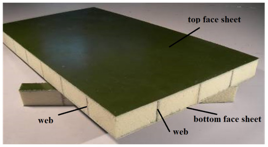
Figure 1.
Sandwich lattice composite panel reinforced with crisscross webs.
LSP can be calculated by several methods, including: (i) Equivalent modulus analysis [16] based on the classical laminate theory, which is hard for the complicated SLCP due to existing webs, which neglect many details of cores and webs and omit the transverse shear stress. (ii) Three-dimension finite element method (FEM), which is usually considered to be omnipotent for complex model construction. However, several issues may block its convenient application, including huge programming workload, calculation efficiency, degree-of-freedom (DOF) coupling among the different types of elements, and inflexible element displacement mode even if general commercial finite-element software is used. (iii) Plate theory is another potential choice for the SLCP analysis, which simplifies the LSP calculation. Various models have been proposed rested on the single-layer theory, layer-wise theory, and zigzag theory respectively.
Kirchhoff’s classic laminate plate theory (CLT) [17] was the first comprehensive theory developed for plates but it did not take the transverse shear strains into consideration. The single-layer theory is also known as first-order shear deformation theory (FSDT) and the disadvantage is lack of a shear correction factor to predict the actual parabolic variation of shear stress and shear locking phenomenon for thin plates, which is still being investigated now [18,19]. To overcome the shortcomings of FSDT, higher order shear deformation theory (HSDT) [20,21] was proposed by Reddy, which is accurate and accounts for the transverse shear deformation and the transverse shear traction-free conditions on the top and the bottom surfaces of the plate without shear correction factor. However, the C1 continuity issue along the interelement boundary promotes the theory development to some degree. The layer-wise theories were presented to surmount that issue. Discrete layer theories were concerned and proposed by A.Toledano, H.Murakami [22], and Reddy [23], which take unknown displacement components through all the layer interfaces. This plate theory possesses good performance, but the numbers of unknowns increase rapidly with the increase of layers that, in fact, lead to huge unaccepted calculations. So, zigzag theories (ZZT, known as refined plate theories) were developed by H. Murakami [24], S.P. Lee, et al. [25] for solving the aforementioned question though the unknowns at different interfaces linking to those at the reference plan unknowns. Improved versions about these theories have been suggested continuously. However, the zigzag theory still faced the C1 continuity issue of the transverse displacement at the nodes by FEM. Combining the benefits of the discrete layer wise and higher order zigzag theories (HOZT), sub-laminate models and penalty stiffness multiplier were propounded to overcome C1 continuity successively for LSP [26,27,28,29,30].
In fact, the improved C0 FE model could receive accurate results efficiently [31,32,33,34]. Chalak et al. [35,36,37,38,39] proposed an improved C0 finite element model for LSP analysis with a soft, compressible core using HOZT. In this model, the in-plane displacement fields as a combination of a linear zigzag function with different slopes at each layer and cubically varying function over the entire thickness are assumed. The out-of-transverse displacement within the core and the surface of face sheets is presumed to be quadratic and constant. This model satisfies the transverse shear stress continuity conditions at the layer interfaces and the conditions of zero transverse shear stress at the top and bottom of the plate, and has made significant contributions: (i) overcoming the C1 continuity problem associated with HOZT to implement a C0 formulation, (ii) possessing great effects on the core compressibility in the formulation, and (iii) eliminating the requirement of using a penalty multiplier in the stiffness matrix formation. The model can also be applied for the ordinary and medium-thick LSP.
In this paper, the improved C0 plate finite element with soft compressible core made use of high-order zigzag theories and the beam element, which is the degeneration form of the above plate element (IC0FEM-HOZT). This finite element was combined to calculate the sandwich lattice composite panel under the out-of-transverse quasi-static loading. Therefore, a type of high efficient analysis method was developed rather than the ordinary three-dimension FEM composed of conventional shell or plate, beam, and solid elements. Nine-nodes-isoparametric-quadratic plate element was used for the face sheets and core. Three-nodes-isoparametric-quadratic beam element, regarded as a type of plate model degeneration, was adopted for the lattice webs cutting apart the core. The spatial occupied core areas by the web volumes can be subtracted by the same virtualized volume web with the core material, or even omitted since the web is very thin and the elastic modulus is far higher than that of the core material. The outstanding performance of that method was presented through numeric calculation compared with the actual test results, including the mid-span deflections and the surface feet normal stresses.
2. Mathematic Model
2.1. Model Displacements
The in-plane displacement fields [28] for the plate, shown in Figure 2, were chosen as follows:
where u0 and v0 are on behalf of the in-plane displacements of any point at the midsurface, θx and θy are the rotations of normal to the middle plane about the y- and x-axis respectively; nu and nl are the number of upper and lower layers respectively; , , , are the higher unknowns; , , , are the slopes of th and th layer corresponding to upper and lower layers respectively, and and are the unit step functions.
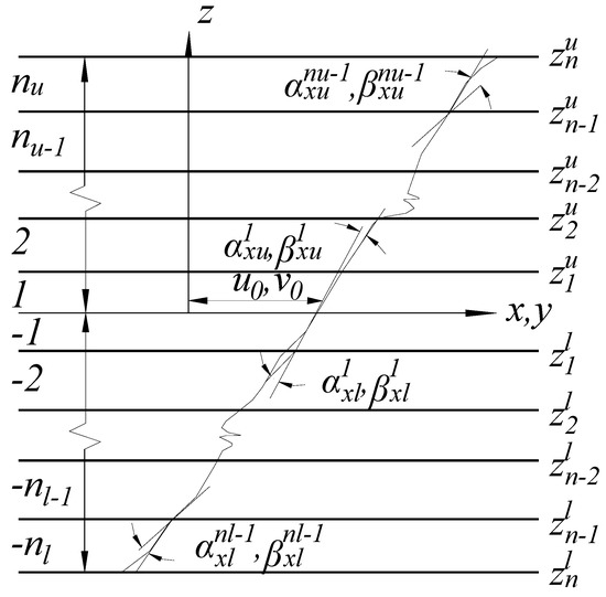
Figure 2.
In-plane displacement fields in laminas.
The out-of-transverse displacement was assumed to vary quadratically through the core thickness and be constant over the face sheets, which is expressed as Equation (3) and shown in Figure 3:
where , , and are the values of the out-of-transverse displacement at the top layer, middle layer, and bottom layer of the core respectively, and l1, l2, l3, are Lagrangian interpolation functions in the thickness co-ordinate as defined in [35,36].
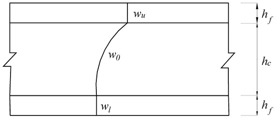
Figure 3.
Out-of-transverse displacement fields.
2.2. Model of Constitutive Relations
The constitutive relationship of any kth orthotropic layer for plate or beam having any fiber orientation with the respect to structural axes system (x-y-z or x-z) is depicted as
where and are the stress vector and the strain vector. is the transformed rigidity matrix of kth layer that can be evaluated with the material properties (E, elastic modulus; v, poisson ratio; G, shear modulus) and fiber orientation of kth layer on mechanics of composite structure.
The detailed Equation (4) for plate is:
The detailed Equation (4) for beam is:
On the conditions of zero transverse shear stress at the top and bottom surfaces of the plate or beam, and the transverse shear stress continuity at the interfaces between the layers with the condition, and at the top, and and at the bottom of the plate, , , , , , , , , , , , and can be expressed by the displacements , , , , , , , and as
where for plate as
For beam as
And elements of are dependent on material properties. The last derivatives entries of the vector help overcome the problem of C1 continuity as mentioned before, including last four items of the plate and last two items of the beam.
According to the above equations, the in-plane displacement fields for plate as given in Equations (1) and (2) may be expressed as
For plate
For beam
where the coefficients bi and ci are functions of thickness coordinates, unit step functions, and material properties as defined in [35,36]. Equations (6)–(8) do not contain any first-order derivative terms of out-of-transverse displacements and avoid the requirements of C1 continuity efficiently without new field variables [28] and penalty method [40,41].
The generalized displacement vector for the plate and beam model can be presented as
For plate
For beam
With the linear constitutive relation and Equations (1)–(5), the strain field can be expressed by unknowns from the structural deformations as
For plate
where Equation (9) can be simplified as ,
For beam
where Equation (10) can be simplified as ,
Where for plate
For beam
And the elements of and are functions of z and unit-step functions, as given in [35,36]
The potential energy of the system can be expressed as
where Us is the strain energy and West is the work due to the elemental out-of-transverse static load.
Equations (4), (9), and (10), Us can be presented by
where for plate
For beam
The work due to the elemental transverse static load P can be calculated by
To solve this problem, a nine-node quadratic element with 11 field variables per node was employed for the plate. A three-node quadratic element with seven field variables per node was employed for the beam, which coordinates the plate element conveniently. The generalized displacement vector at any point for any plate or beam can be expressed as
where for plate, and for beam. is the displacement vector corresponding to node i of plate or beam element; is the shape function associated with node i and n is the number of nodes per element, that is, nine for the plate or three for the beam.
With the help of Equation (16), the strain vector for the plate or beam can be expressed in terms of the generalized displacement vector or as
where or are the strain-displacement matrices in the Cartesian coordinate system.
The elemental potential energy as given in Equation (11) can be rewritten as
where
where is the shape function like matrix with non-zero terms associated only with the corresponding out-of-transverse nodal displacements. Though the beam element node lacks partial field variables, the existing ones are all included in the plate-element-node field variables and are easy to extend to the plate’s.
In accordance with Principle of Minimum Potential Energy, minimizing as given in Equation (19) with respect to , the equilibrium equation is
where is the element stiffness matrix, and is the nodal load vector.
The global stiffness matrix was formed by taking the contribution of all the plate elements and beam elements. The formation of the global load vector for the whole SLCP was just formed in consideration of the plate elements that contain the all-beam nodes. Then, the global linear simultaneous equations were formed and solved for the SLCP incorporating appropriate boundary conditions. In order to improve the displacements-calculation efficiency by the FE model, the sparse-matrix technique was utilized to store the global stiffness matrix. The stresses were calculated with the constitutive relationship by using the condition of stress continuity as in Equation (5). Meanwhile, this model, combined with the improved C0 Zigzag plate model and its degeneration beam model, naturally circumvented the DOF coupling, made the beam and plate deformation compatible, and simplified the programming process.
3. Comparison Cases
To verify the effectiveness of the aforementioned improved C0 finite element method on the ground of HOZT (IC0FEM-HOZT), the corresponding test results were compared here. Two cases about SLCP flexural experiments in the literature are presented as the referenced examples in the following sections [14,15].
3.1. Case 1: Two-Way Simply Supported SLCP under the Concentrated Load
3.1.1. Specimen and Experiment Introduction
Five two-way reinforced SLCPs, composed of GFRP face sheets, GFRP webs, and rigid polyurethane foam cores, by vacuum-assisted resin infusion process, were tested under the concentrated load, which was loaded by the hydraulic actuator. The face sheet was formed by 0°/90°GFRP clothes, and the web sheet consisted of −45°/45°GFRP clothes. That length and width of all SLCP specimens were 1000 mm, while the effective support spans were both 910 mm. The side length of the core and the lattice web spacing varied from 75 mm, 125 mm, and 175 mm. The geometric details of SLCP specimens are described in Table 1, and the material properties of SLCPs are listed in Table 2. The experimental scheme is shown in Figure 4, where LVDT for the out-of-transverse deflection was set up under the bottom of the SLCP, as shown in Figure 5.

Table 1.
Details of the specimens.
Table 2.
Material properties.
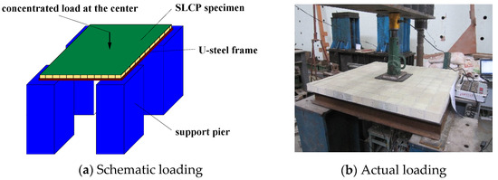
Figure 4.
Loading schematic for two-way simply supported SLCPs.
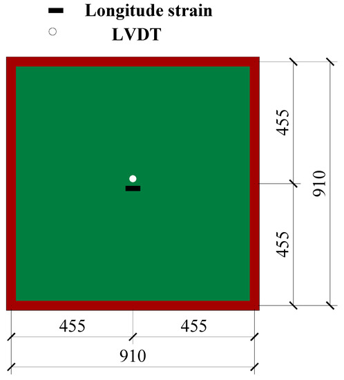
Figure 5.
LVDT for the out-of-transverse deflection scheme.
3.1.2. Results and Discussion
The out-of-transverse displacements and face-plate normal stresses of the flexural experiment of SLCPs are discussed here. Figure 6 shows the test load-deflection curves compared to the top, mid, and bottom surface out-of-plane vertical deflections by FEM. Figure 7 shows the load-stress curves on the mid bottom surface. Table 3 lists the deflections and surface normal stresses corresponding to the ultimate bearing capacity.
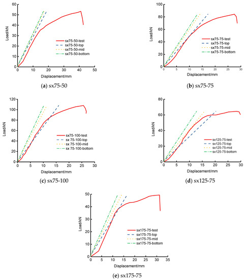
Figure 6.
Load-deflection curves under the concentrated load for two-way simply supported SLCPs.
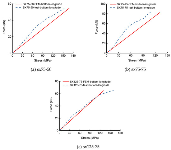
Figure 7.
Load-stress curves on the bottom surface of two-way simply supported SLCPs.
Table 3.
The mid deflection and normal stress under the ultimate bearing capacity.
In accordance with Table 3, the bottom deflection errors between the test and FEM for two-way simply supported SLCPs were within 52–61%. The bottom surface normal stress errors were within 8–22%. However, Figure 6 presents that the test load-deflection curves were evidently elastoplastic. During the elastic stage, the FEM load-deflection curves including the top, mid surface, and bottom were very close to the tests’. Figure 7 presents that the test load-stress curves were weak nonlinear until the ultimate stage. During the whole loading history, the FEM bottom stress curves became close to the tests’.
3.2. Case 2: Single-Way Simply Supported SLCPs under Uniformly Concentrated Load
3.2.1. Specimen and Experiment Introduction
Two unidirectional-web and six bidirectional-web reinforced SLCPs, manufactured by vacuum-assisted resin infusion process as in Case 1, were tested under four-point load action. The face sheet was formed by 0°/90°GFRP clothes, and the web sheet was composed of −45°/45°GFRP clothes. That length of all SLCP specimens were 1000 mm, while the effective support spans were both 800 mm, and the width was 300 mm. The side length of the core and the lattice web spacing were 75 mm. The geometric details of SLCP specimens are described in Table 4, and the material properties of SLCPs are listed in Table 5. The experimental scheme is shown in Figure 8, where three LVDTs for the out-of-transverse displacements were set up under the bottom of the SLCP and the top specimen surface at support; the longitudinal and in-plane transverse normal stress on the top and bottom surface center at the midspan.
Table 4.
Details of specimens.
Table 5.
Material properties.
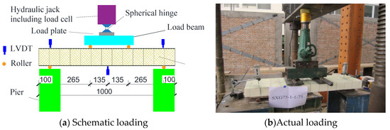
Figure 8.
Loading schematic for single-way simply supported SLCPs.
3.2.2. Results and Discussion
To verify the results with the aforementioned IC0FEM-HOZT, the corresponding test results were compared. The out-of-transverse displacements and bilateral normal stresses of the top and bottom midspan face sheets by the flexural experiment for the single-way simply supported SLCPs are discussed here. Figure 9 shows the load-midspan out-of-transverse deflection curves. Figure 10 shows the load-bilateral stress curves on the midspan top and bottom surfaces. Table 6 lists the deflections corresponding to the ultimate bearing capacity. Table 6 lists the deflection corresponding to the ultimate bearing capacity of the test. Table 7 lists that the bilateral midspan normal stresses on the top and bottom surfaces under the ultimate bearing capacity.
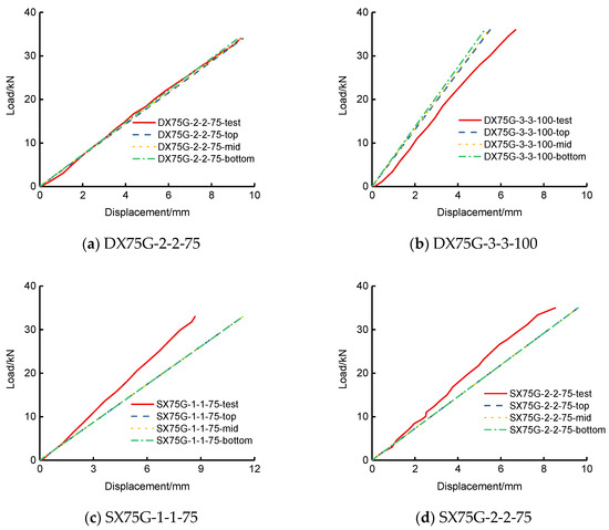
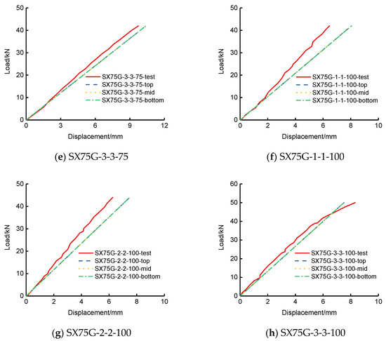
Figure 9.
Load-midspan curves under the concentrated load for single-way simply supported SLCPs.
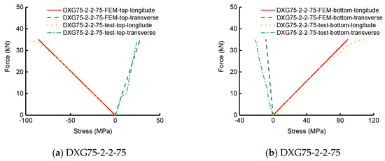
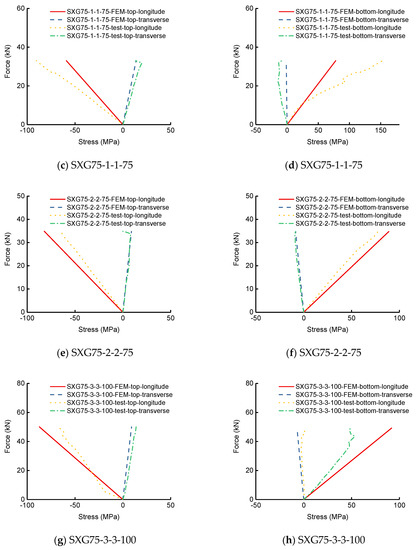
Figure 10.
Load-normal stress curves on the mid, top, and bottom surfaces of single-way simply supported SLCPs.
Table 6.
The mid deflection under the ultimate bearing capacity.
Table 7.
The bilateral midspan normal stress under the ultimate bearing capacity.
In accordance with Table 6, the bottom deflection errors between the test and FEM for single-way simply supported SLCPs were within 1–31%. Based on Table 7, the longitudinal normal stress errors on the top surface were within 11–35%; the transverse errors were within 2–35% except for SXG-2-2-75, which cannot be estimated by the current error method; the longitudinal normal stress errors at the bottom surface were within 14–50%; the transverse errors were within 3–140%. Both the test load-midspan deflection curves and load-stress curves took on elastic, generally, according to Figure 9 and Figure 10. During the whole loading stage, the FEM results including on the top, at the midsurface, and at the bottom were close to the tests’. However, the sudden change of test data at the ultimate loading end showed the nonlinear effect evidently, which can lead to large errors on the relative deflection and normal stress.
4. Conclusions
In this study, nine-nodes-isoparametric-quadratic plate element and three-nodes-isoparametric-quadratic beam element were combined to simulate the sandwich lattice composite panel with the improved C0 finite element method with the soft compressible core using high-order zigzag theories. The deflections and normal results of SLCPs under the out-of-plane quasi-static loading with FEM were compared to those by the test.
As a whole, the combination method by the improved C0 finite plate element and the beam element degenerated from the improved C0 finite plate element, based on high-order zigzag theories, is a suitable method for the analysis of the sandwich lattice composite panel. IC0FEM-HOZT can avoid the conventional three-dimension hybrid element model composed by cube element, shell element, and beam, which usually may lead to a complicated building program, and the coupling degrees of freedom among the different types of elements. Though some deviation still exists between the calculation results by IC0FEM-HOZT and those by test due to the multiple causes such as nonlinear, IC0FEM-HOZT has great potential to become an excellent and highly efficient analysis and design tool for the sandwich lattice composite panel, if appropriate modifications are adopted according to the actual work.
Author Contributions
Conceptualization, H.F.; methodology, H.F.; validation, L.Y.; investigation, J.H.; data curation, J.H.; writing—original draft preparation, J.H.; writing—review and editing, C.S. and L.Y.; supervision, W.L. All authors have read and agreed to the published version of the manuscript.
Funding
This research received no external funding.
Institutional Review Board Statement
Not applicable.
Informed Consent Statement
Not applicable.
Data Availability Statement
Data available in a publicly accessible repository.
Acknowledgments
The research described in this study was supported by the National Key Research and Development Program of China (Grant No. 2019YFD1101205), the National Natural Science Foundation of China (Grant No. 52078248) and the Natural Science Foundation for Distinguished Young Scholars of Jiangsu Province (Grant No. BK20190034). Thanks also go to Abdul Hamid Sheikh for his contribution to this study.
Conflicts of Interest
The authors declare no conflict of interest.
References
- Le, V.T.; Ha, N.S.; Goo, N.S. Advanced sandwich structures for thermal protection systems in hypersonic vehicles: A review. Compos. Part B Eng. 2021, 226, 109301. [Google Scholar] [CrossRef]
- Ha, N.S.; Lu, G. A review of recent research on bio-inspired structures and materials for energy absorption applications. Compos. Part B Eng. 2020, 181, 107496. [Google Scholar] [CrossRef]
- Manalo, A.; Aravinthan, T.; Karunasena, W. Flexural behaviour of glue-laminated fibre composite sandwich beams. Compos. Struct. 2010, 92, 2703–2711. [Google Scholar] [CrossRef]
- Ha, N.S.; Lu, G.; Xiang, X. Energy absorption of a bio-inspired honeycomb sandwich panel. J. Mater. Sci. 2019, 54, 6286–6300. [Google Scholar] [CrossRef]
- Darzi, S.; Karampour, H.; Gilbert, B.P.; Bailleres, H. Numerical study on the flexural capacity of ultra-light composite timber sandwich panels. Compos. Part B Eng. 2018, 155, 212–224. [Google Scholar] [CrossRef]
- Eckardt, J.; Neubauer, J.; Sepperer, T.; Donato, S.; Zanetti, M.; Cefarin, N.; Vaccari, L.; Lippert, M.; Wind, M.; Schnabel, T.; et al. Synthesis and Characterization of High-Performing Sulfur-Free Tannin Foams. Polymers 2020, 12, 564. [Google Scholar] [CrossRef] [PubMed]
- Fernando, P.; Jayasinghe, M.; Jayasinghe, C. Structural feasibility of Expanded Polystyrene (EPS) based lightweight concrete sandwich wall panels. Constr. Build. Mater. 2017, 139, 45–51. [Google Scholar] [CrossRef]
- Peliński, K.; Smardzewski, J. Bending Behavior of Lightweight Wood-Based Sandwich Beams with Auxetic Cellular Core. Polymers 2020, 12, 1723. [Google Scholar] [CrossRef]
- Galatas, A.; Hassanin, H.; Zweiri, Y.; Seneviratne, L. Additive Manufactured Sandwich Composite/ABS Parts for Unmanned Aerial Vehicle Applications. Polymers 2018, 10, 1262. [Google Scholar] [CrossRef] [PubMed]
- Li, Y.; Chen, C.; Hou, H.; Cheng, Y.; Gao, H.; Zhang, P.; Liu, T. The Influence of Spraying Strategy on the Dynamic Response of Polyurea-Coated Metal Plates to Localized Air Blast Loading: Experimental Investigations. Polymers 2019, 11, 1888. [Google Scholar] [CrossRef]
- Fang, H.; Sun, H.; Liu, W.; Wang, L.; Bai, Y.; Hui, D. Mechanical performance of innovative GFRP-bamboo-wood sandwich beams: Experimental and modelling investigation. Compos. Part B Eng. 2015, 79, 182–196. [Google Scholar] [CrossRef]
- Zhu, D.; Shi, H.; Fang, H.; Liu, W.; Qi, Y.; Bai, Y. Fiber reinforced composites sandwich panels with web reinforced wood core for building floor applications. Compos. Part B Eng. 2018, 150, 196–211. [Google Scholar] [CrossRef]
- Chen, J.; Fang, H.; Liu, W.; Qi, Y.; Zhu, L. Experimental and Numerical Analysis of Nonlinear Flexural Behaviour of Lattice-Web Reinforced Foam Core Composite Sandwich Panels. Adv. Civ. Eng. 2018, 2018, 2972931. [Google Scholar] [CrossRef]
- Chen, X.Q.; Liu, W.Q.; Fang, H. Experimental Study of Flexural Behavior of Composite Sandwich Panel Reinforced by Two-Way Webs. J. Exp. Mech. 2012, 27, 486–491. (In Chinese) [Google Scholar]
- Liu, Z.J.; Liu, W.Q.; Wan, L. Flexural Behavior of Two-way Fiber Reinforced Sandwich Structure. J. Mater. Sci. Eng. 2012, 30, 765. (In Chinese) [Google Scholar]
- Allen, H.G. Analysis and Design of Structural Sandwich Panels; Elsevier: Amsterdam, The Netherlands, 1969. [Google Scholar]
- Love, A.E.H. XVI. The small free vibrations and deformation of a thin elastic shell. Philos. Trans. R. Soc. A Math. Phys. Eng. Sci. 1888, 179, 491–546. [Google Scholar] [CrossRef]
- Whitney, J.M.; Pagano, N.J. Shear deformation in heterogeneous anisotropic plates. J. Appl. Mech. Trans. ASME 1970, 37, 1031–1036. [Google Scholar] [CrossRef]
- Ferreira, A.J.M. A formulation of the multiquadratic radial basis function method for the analysis of laminated composite plates. Compos. Struct. 2003, 59, 385–392. [Google Scholar] [CrossRef]
- Reddy, J.N. A Simple Higher-Order Theory for Laminated Composite Plates. J. Appl. Mech. 1984, 51, 745–752. [Google Scholar] [CrossRef]
- Kant, T.; Swaminathan, A. Analytical solutions for the static analysis of laminated composite and sandwich plates based on refined higher order shear deformation theory. Compos. Struct. 2002, 56, 329–344. [Google Scholar] [CrossRef]
- Toledano, A.; Murakami, H. Composite plate theory for arbitrary laminate configuration. J. Appl. Mech. 1987, 54, 181–189. [Google Scholar] [CrossRef]
- Reddy, J.N. A generalization of two-dimensional theories of laminated composite plates. Commun. Appl. Numer. Methods 1987, 3, 173–180. [Google Scholar] [CrossRef]
- Murakami, H. Laminated Composite Plate Theory with Improved In-Plane Responses. J. Appl. Mech. 1986, 53, 661–666. [Google Scholar] [CrossRef]
- Lee, K.; Senthilnathan, N.; Lim, S.; Chow, S. An improved zig-zag model for the bending of laminated composite plates. Compos. Struct. 1990, 15, 137–148. [Google Scholar] [CrossRef]
- Cho, Y.B.; Averill, R.C. An improved theory and finite element model for laminated beams using first order zigzag sub-laminate approximations. Compos. Struct. 1997, 37, 281–298. [Google Scholar] [CrossRef]
- Chakrabarti, A.; Sheikh, A.H. A new triangular element to model inter-laminar shear stress continuous plate theory. Int. J. Numer. Methods Eng. 2004, 60, 1237–1257. [Google Scholar] [CrossRef]
- Fares, M.E.; Elmarghany, M.K. A refined zigzag non-linear first order shear deformation theory of composite laminated plates. Compos. Struct. 2008, 82, 71–83. [Google Scholar] [CrossRef]
- Shimpi, R.P.; Ghugal, Y.M. A new layerwise trigonometric shear deformation theory for two layered cross-ply beams. Compos. Sci. Technol. 2001, 61, 1271–1283. [Google Scholar] [CrossRef]
- Arya, H.; Shimpi, R.; Naik, N. A zigzag model for laminated composite beams. Compos. Struct. 2002, 56, 21–24. [Google Scholar] [CrossRef]
- Yip, Y.C.; Averill, R.C. Thick beam theory and finite element model with zigzag sub-laminate approximations. AIAA J. 1996, 34, 1627–1632. [Google Scholar]
- Yu, H.; Bai, Y.-L.; Dai, J.-G.; Gao, W.-Y. Finite Element Modeling for Debonding of FRP-to-Concrete Interfaces Subjected to Mixed-Mode Loading. Polymers 2017, 9, 438. [Google Scholar] [CrossRef]
- Carrera, E. C0 Reissner-Mindlin miltilayered plate element including zigzag and interlaminar stress continuity. Int. J. Numer. Meth. Eng. 1996, 39, 1797–1820. [Google Scholar] [CrossRef]
- Averill, R.C.; Yip, Y.C. Development of simple, robust finite elements based on refined theories for thick laminated beams. Compos. Struct. 1996, 59, 661–666. [Google Scholar] [CrossRef]
- Chakrabarti, A.; Iqbal, M.; Sheikh, A. An efficient FE model for the analysis of laminated sandwich beam with soft core. Compos. Struct. 2011, 93, 271–279. [Google Scholar] [CrossRef]
- Chalak, H.D.; Chakrabarti, A.; Iqbal, M.A.; Sheikh, A.H. An improved C0 FE model for the analysis of laminated sandwich plate with soft core. Finite Elem. Anal. Des. 2012, 56, 20–31. [Google Scholar] [CrossRef]
- Khandelwal, R.; Chakrabarti, A.; Bhargava, P. A New C0 2D Fe Model Based on Improved Higher Order Zigzag Theory for the Analysis of Soft Core Sandwich Plate. Int. J. Appl. Mech. Eng. 2013, 18, 395–423. [Google Scholar] [CrossRef][Green Version]
- Sarangan, S.; Singh, B.N. Improved zigzag theories for laminated composite and sandwich plates with interlaminar shear stress continuity. Aerosp. Sci. Technol. 2016, 52, 243–255. [Google Scholar] [CrossRef]
- Anish, A.; Kumar, A.; Chakrabarti, A. Failure mode analysis of laminated composite sandwich plate. Eng. Fail. Anal. 2016, 104, 950–976. [Google Scholar] [CrossRef]
- Pandit, M.K.; Sheikh, A.H.; Singh, B.N. An improved higher order zigzag theory for the static analysis of laminated sandwich plate with soft core. Finite Elem. Anal. Des. 2008, 44, 602–610. [Google Scholar] [CrossRef]
- Pandit, M.K.; Sheikh, A.H.; Singh, B.N. Stochastic free vibration response of soft core sandwich plates using an improved higher or der zigzag theory. J. Aerosp. Eng. 2010, 23, 14–23. [Google Scholar] [CrossRef]


Publisher’s Note: MDPI stays neutral with regard to jurisdictional claims in published maps and institutional affiliations. |
© 2021 by the authors. Licensee MDPI, Basel, Switzerland. This article is an open access article distributed under the terms and conditions of the Creative Commons Attribution (CC BY) license (https://creativecommons.org/licenses/by/4.0/).