Abstract
Ground Penetrating Radar (GPR) has proved to be a successful technique for the detection of landmines and Improvised Explosive Devices (IEDs) buried in the ground. In the last years, novel architectures for safe and fast detection, such as those based on GPR systems onboard Unmanned Aerial Vehicles (UAVs), have been proposed. Furthermore, improvements in GPR hardware and signal processing techniques have resulted in a more efficient detection. This contribution presents an experimental validation of a hybrid Forward-Looking–Down-Looking GPR architecture. The main goal of this architecture is to combine advantages of both GPR architectures: reduction of clutter coming from the ground surface in the case of Forward-Looking GPR (FLGPR), and greater dynamic range in the case of Down-Looking GPR (DLGPR). Compact radar modules working in the lower SHF frequency band have been used for the validation of the hybrid architecture, which involved realistic targets.
1. Introduction
1.1. Background
Non-invasive detection of buried objects can be conducted using different techniques, such as ultrasound, magnetic induction (metal detectors), and Ground Penetrating Radar (GPR). The latter is suitable to detect either metallic or non-metallic targets [1], making it appropriate for infrastructure inspection [2,3], archaeological survey [4], material characterization [5] or landmine and Improvised Explosive Devices (IEDs) detection [6,7].
GPR systems can be classified according to different parameters and criteria. Most GPR systems operate in a monostatic or quasi-monostatic configuration (in which the receiving and transmitting antennas are close to each other in terms of wavelengths). These systems can be further grouped in Forward-Looking GPR (FLGPR) and Down-Looking GPR (DLGPR). In the former the GPR antennas are looking ahead from the platform or vehicle performing the GPR scanning [8], whereas in the latter the antennas are pointing normal to the ground [9,10]. An alternative configuration consists of bistatic GPR systems, in which the transmitting and receiving antennas are located far from each other (in terms of wavelengths) [11].
In the case of DLGPR, the distance between the GPR antennas and the scanned region is smaller than in FLGPR, thus enabling greater dynamic range as well as better resolution. However, the GPR signal reflection at the air–ground interface is also greater in DLGPR, thus jeopardizing the detection of shallow targets (as is the case of most landmines and IEDs).
In contrast, FLGPR architectures avoid the normal reflection on the air–ground interface, thus minimizing the clutter coming from the air–ground interface, but at the expense of worse dynamic range due to greater propagation losses. FLGPR systems are thus suitable for detecting shallow targets. In general, FLGPR systems are mounted onboard terrestrial vehicles, as the oblique incidence allows keeping a safe distance between the vehicle and the scanning area where landmines, IEDs and Unexploded Ordnances (UXOs) can be buried [12]. However, there is a clear risk for the vehicle (and its operator/driver) if a buried explosive target is not detected. To improve the detection probability, several signal processing techniques have been proposed in the field of FLGPR systems [13].
Recently, GPR systems onboard Unmanned Aerial Vehicles (UAVs) have been developed [14,15,16,17,18]. In fact, both academia and industry show great interest in these systems due to their advantages in terms of safety, speed and capability to inspect difficult-to-access areas. It is worth noting that, unlike terrestrial vehicles, contact with the ground, and thus the risk of accidental detonation of buried explosives, is avoided. Most UAV-based GPR systems are based on DLGPR architectures [14,15,16,17] to maximize range resolution and dynamic range (at the expense of stronger clutter contributions from the air–ground interface), although side-looking GPR has also been assessed in [18].
The development of a GPR system combining the advantages of FLGPR and DLGPR architectures would result in better detection capabilities, which is of special interest for the detection of buried explosives (landmines, IEDs, UXOs). A feasibility study has been presented in [19], where the proposed hybrid FLGPR-DLGPR was evaluated using ray-tracing and Finite-Difference Frequency-Domain (FDFD) simulation methods, comparing the achieved performance against conventional FLGPR and DLGPR.
1.2. Aim and Scope
This contribution presents the implementation and validation of the hybrid FLGPR-DLGPR proposed in [19]. From the technical point-of-view, one of the major challenges to be addressed is related to the synchronization between the transmitter and the receiver, which must be physically decoupled for operational purposes. In particular, the use of radiofrequency cables connecting two radar modules placed several meters away would not be feasible in the case of UAV-based GPR architectures. The main goal is to prove that non-metallic targets buried only a few centimeters under the ground can be detected, as the air-ground reflection is mitigated. The portable setup presented in [20] has been fitted to accommodate the hybrid FLGPR-DLGPR architecture for its validation.
In this sense, it is important to remark that the proposed hybrid FLGPR-DLGPR system is intended to complement DLGPR architectures, which have been successfully used for detecting deeper targets.
2. Methodology
2.1. Overview of the Hybrid FLGPR-DLGPR Architecture
In order to introduce and compare the proposed hybrid FLGPR-DLGPR architecture [19], the most common GPR architectures (described in Section 1) and the proposed one are depicted in Figure 1. Figure 1a corresponds to a DLGPR system where the GPR antennas are oriented towards the ground with normal incidence. Figure 1b shows an FLGPR architecture, being the GPR antennas several meters away from the imaging domain and oriented at grazing incidence. The proposed hybrid FLGPR-DLGPR architecture is depicted in Figure 1c,d, where the transmitter antenna (at grazing incidence) is placed at several meters from the receiver (pointing normal to the ground). Figure 1c corresponds to the case where the transmitter is static and the receiver moves over the scanning area, whereas the transmitter moves synchronously with the receiver in Figure 1d.
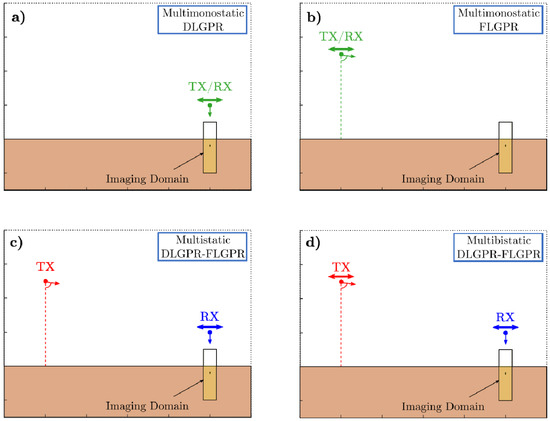
Figure 1.
Schemes of different Ground Penetrating Radar (GPR) architectures [21]: conventional Down-Looking GPR (DLGPR) (a) and Forward-Looking GPR (FLGPR) (b) configuration; proposed hybrid FLGPR-DLGPR architectures in which the transmitter is static (c) and the transmitter moves synchronously with the receiver (d).
These four configurations were compared considering a realistic scenario in Section 4 (“Analysis”) of [19], where a 10 cm × 4 cm size plastic landmine is buried in a sandy soil with a rough surface. Simulations using FDFD were conducted in the 3.5–5.5 GHz frequency band and they were post-processed using a Synthetic Aperture Radar (SAR) algorithm. The resulting GPR-SAR images can be found in Figure 2. The buried landmine cannot be detected with DLGPR (Figure 2a) nor with FLGPR (Figure 2b) configurations: in the case of the DLGPR most of the incident power is reflected at the air–ground interface, whereas the FLGPR architecture exhibits poor resolution. The hybrid FLGPR-DLGPR architecture successfully combines the advantages of FLGPR and DLGPR as it can be noticed in Figure 2c,d: the air–ground reflection is mitigated with respect to DLGPR, while keeping a good resolution in the GPR-SAR image. As a result, reflections coming from the buried target can be identified. It can be noticed that there are no significant differences between considering a static transmitter (Figure 2c) or moving it synchronously with the receiver (Figure 2d). Thus, for the sake of simplicity, the hybrid FLGPR-DLGPR architecture in which the transmitter is static has been considered to perform the experimental validation.
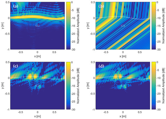
Figure 2.
Synthetic Aperture Radar (SAR) image from Finite-Difference Frequency-Domain (FDFD) simulations with a flat-top dielectric target buried under a rough surface (dashed line indicates the soil surface) extracted from [19]: conventional DLGPR (a) and FLGPR (b) configuration; proposed hybrid FLGPR-DLGPR architectures in which the transmitter is static (c) and the transmitter moves synchronously with the receiver (d).
A scheme of the hybrid FLGPR-DLGPR architecture to be implemented and validated is shown in Figure 3. The transmitter will be kept static whereas the receiver will be moved over the scenario under test (that is, the GPR imaging domain). Transmitter and receiver modules must be synchronized to enable the coherent processing of the measurements, not only in range, but also in cross-range (i.e., along the axes orthogonal to the vertical range axis). Assuming ideal conditions, the transmitting antenna will be pointed towards the center of the imaging domain. Part of the incident field (Einc) will be reflected (Erefl) in the ground surface, but little or none reflected field will be captured by the receiving antenna, as the specular reflections from the ground surface will not reach it. Another part of the incident field will be transmitted into the ground (Etrans) and, in case of a buried target is present, it will be scattered back to the ground surface (Escatt). Finally, a portion of this scattered field might eventually reach the receiving antenna.
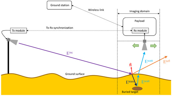
Figure 3.
Scheme of the proposed hybrid FLGPR-DLGPR.
Radar measurements are collected at the receiver during the data acquisition and sent to a ground station via a wireless link for further processing. In particular, SAR processing is applied to achieve greater cross-range resolution.
2.2. Radar System Implementation and Processing
As indicated at the end of Section 1, the main issue concerning the implementation of the hybrid FLGPR-DLGPR is the wireless synchronization of the transmitting and receiving radar modules. A set of two PulsOn P440 radar modules [22], working in the 3–5 GHz frequency band, has been selected as these modules can be synchronized without requiring a physical connection between them. Therefore, they are suitable for bistatic and multistatic radar architectures, such as the proposed one. To perform the synchronization the receiving module looks for the first strong arriving signal to determine the time-of-flight. In the hybrid FLGPR-DLGPR architecture, the direct ray between the transmitter and the receiver might be very weak, as the receiving antenna is pointing towards the ground. This caused synchronization issues in the first experiments with these radar modules, as reflections on the ground were interpreted by the radar as the first strong arriving signal.
To overcome these problems, the hardware architecture shown in Figure 4 has been implemented. An additional receiving antenna, denoted as DR Rx antenna, pointing towards the transmitting antenna, has been included in the receiving front-end of the system. Both receiving antennas are connected to a power combiner, the output of which is connected to the receiving radar module. In order to better distinguish between the contributions captured by this DR Rx antenna and the ones captured by the DL-GPR Rx antenna, a delay line, consisting of a 2 m coaxial cable, has also been added between the latter and the power combiner (see Figure 4).
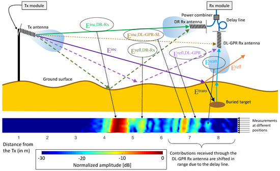
Figure 4.
Scheme of the implemented hybrid FL-DL GPR system. Identification of the different received contributions in the retrieved reflectivity plotted as a function of the distance from the transmitter for several measurements.
As shown in Figure 4, the main contributions captured by the DR Rx antenna will be the direct Tx-Rx contributions, Einc,DR-Rx. Specular reflections in the ground, Erefl,DR-Rx, will also be captured, but delayed from Einc,DR-Rx and exhibiting less amplitude, as shown in the reflectivity chart plotted in Figure 4. Concerning the signals captured by the DL-GPR Rx antenna, the first to be received would be the direct Tx-Rx contribution, Einc-DL-GPR-SL, captured through a sidelobe of the DL-GPR Rx antenna. Depending on the sidelobe level and the antenna polarization, this contribution may exhibit an amplitude comparable to Einc,DR-Rx (as it is the case in the example shown in Figure 4). The next contribution that can be identified is the ray reflected on the ground, Erefl,DL-GPR. Finally, contributions corresponding to the field scattered by the targets located within the scanning area, Escatt, are received.
Thanks to the use of the delay line, contributions received through the DL-GPR Rx antenna can be better distinguished from contributions received through the DR Rx antenna, just by means of spatial filtering.
Concerning the radar signal processing, the following procedure is applied for each measurement:
- (1)
- The peak of the received time-domain radar signal, which will correspond to Einc,DR-Rx, is identified, so that the time-of-flight is extracted.
- (2)
- A spatial filter is applied to get rid of the contributions captured by the DR Rx antenna. Then, the phase shift introduced by the 2 m-length delay line is compensated.
- (3)
- Contributions Einc-DL-GPR-SL and Erefl,DL-GPR are filtered out by means of another spatial filter, so that the remaining signal peaks would correspond to Escatt.
Once all the measurements have been collected and processed, standard GPR-SAR is applied. First, for each position of the receiver (x, y, z), radar measurements Escatt(t, x, y, z) are transformed into the frequency domain, Escatt(f, x, y, z). Then, the reflectivity at each point of the imaging domain, ρ(x′, y′, z′), is calculated (1):
being Nf the number of discrete frequencies in which the working frequency band of the radar modules is discretized, and NRx,meas the number of measurement points. k0(f) is the wavenumber in free-space. RTx and RRx are the distance between the transmitting antenna and the point of the imaging domain (x′, y′, z′) where the reflectivity is computed, and the distance between this point of the imaging domain and the receiving antenna (DL-GPR Rx antenna), respectively (2), (3):
For the sake of clarity, results presented in this contribution are obtained considering free-space propagation (i.e., the relative permittivity of the entire imaging domain is set to 1).
2.3. Description of the Hardware of the Measurement Setup
The measurement setup described in [20] has been adapted to perform multistatic measurements, resulting in the hardware implementation shown in Figure 5. The transmitting radar module connected to the transmitting antenna has been mounted on a wooden frame located about 5 m away from the center of the scanned area. The height of the transmitting antenna is zTx = 105 cm. The DR Rx and DL-GPR Rx antennas are mounted on the plastic box shown in Figure 6, where the delay line consisting of a 2 m coaxial cable can be observed. The receiving radar module is connected to a micro-computer that also collects positioning and geo-referring information. The geo-referred radar measurements are sent to a ground station (a laptop) using an ad-hoc wireless link [20].
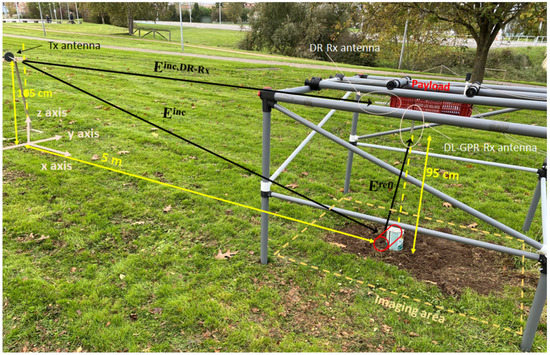
Figure 5.
Picture of the implemented FLGPR-DLGPR system. Tested target: metallic can (the profile of the metallic can when laid down is plotted in red color).
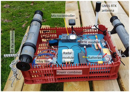
Figure 6.
Picture of the devices mounted on the plastic box of the portable scanner.
The plastic box shown in Figure 6 is mounted onto a sliding arm that can be manually displaced along a distance of approximately 150 cm in the x-axis, as described in [20]. The sliding arm can also be moved the same distance in the y-axis. A linear sweep is performed by displacing the plastic box along the sliding arm on top of the frame of the setup. After performing a round-trip sweep along the x-axis, the sliding arm is manually moved along the y-axis to another position. Due to the size of the plastic box, the dimensions of the scanning area are restricted to 100 cm × 100 cm, approximately. The DL-GPR RX antenna is around 85 cm above-ground.
As mentioned before, a set of two radar modules working in the 3–5 GHz frequency band has been selected. Furthermore, helix antennas have been used for the following reasons: (i) they exhibit good performance in terms of impedance matching and radiation pattern directivity in the 3 to 5 GHz frequency band, which is the working frequency band of the radar modules, and (ii) they have good polarization purity, thus enabling better polarization discrimination of the received signals. In this sense, the DR Rx antenna has the same polarization as the Tx antenna, whereas the DL-GPR Rx antenna has orthogonal polarization with respect to the Tx antenna because of the polarization rotation introduced by the reflection coefficient of the ground.
Positioning and geo-referring information is provided by a dual-band Global Navigation Satellite System (GNSS)–Real Time Kinematics (RTK) system, consisting of a GNSS-RTK antenna and a GNSS-RTK module [23]. RTK can provide positioning information within 1–2 cm accuracy. Finally, the hardware shown in Figure 6 is powered using a LiPo battery. Transmitting and receiving radar modules are equipped with their own battery modules.
3. Results
3.1. Testing Using a Metallic Target Above Ground
First, the hybrid FLGPR-DLGPR system was tested using a calibration target placed on the ground. The calibration target, a 15 cm-diameter by 17 cm-height cylindrical metallic can, was placed in the position shown in Figure 5. Two tests were conducted, one with the metallic can as shown in Figure 5 (axis of the cylindrical can parallel to the z axis, i.e., orthogonal to the ground surface), and another with the metallic can laid down so that the axis of the cylindrical can was parallel to the y axis (i.e., the axis was parallel to the ground surface). It was found that the field scattered by the metallic can was greater in this second scenario, making the detection of the metallic can easier. In consequence, this configuration was chosen for validation purposes. Measurements were conducted in a continuous sweep along the x-axis, as shown in Figure 7. For each position along the y-axis, two sweeps along the x-axis were performed (a round-trip sweep).
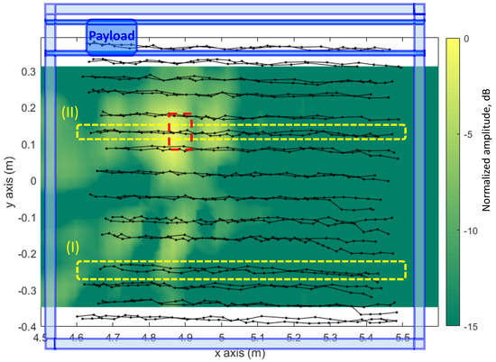
Figure 7.
Measurement positions in the XY plane superimposed on the GPR-SAR image retrieved on the z = 7 cm XY plane. Black dots (•) indicate individual acquisition positions. Measurement positions corresponding to the same sweep along the x-axis are connected with a solid black line. The placement of the metallic can, being the axis of the cylindric can aligned with the y axis, is highlighted with a dashed red line. For reference purposes, a sketch of the layout of the portable setup [20] is depicted in blue color.
To better illustrate the processing technique, two individual sweeps denoted as (I) and (II) (highlighted with dashed yellow rectangles in Figure 7) have been selected. It should be noted that the individual sweep denoted as (II) intersects the position of the metallic can laid down on the ground. Each individual measurement is processed following the methodology explained in Section 2.2. Results after the second step (i.e., after removing the contributions of the DR Rx antenna and compensating the delay line) for the (I) and (II) sweeps are depicted in Figure 8a,b, respectively. The contribution corresponding to Einc-DL-GPR-SL is the one exhibiting the maximum amplitude. It can be noticed that its location in range increases as the receiver moves away from the transmitter. In the case of Figure 8b, reflections coming from the metallic can (i.e., the scattered field, Escatt) are observed in the range distance of about 6 m.
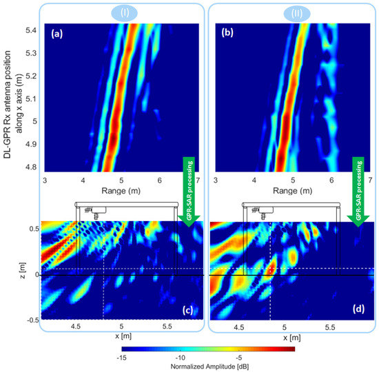
Figure 8.
Individual processing of the cuts corresponding to the x-axis sweeps highlighted with dashed yellow rectangles in Figure 7, not intersecting (I) and intersecting (II) the position of the metallic can. (a) and (b) correspond to the range measurements for each acquisition position along the x-axis, and (c) and (d) are the reflectivity images in the XZ plane after applying GPR-SAR processing. For reference purposes, the air–ground interface (z = 0 m) and a sketch of the layout of the portable setup are depicted in black color in (c) and (d).
Next, reflectivity images from each of the selected individual sweeps, denoted as (I) and (II), are retrieved applying GPR-SAR processing. It should be noted that in this case, as only single sweeps are considered, a two-dimensional (2D) GPR-SAR processing is conducted in the vertical plane parallel to the movement direction during each sweep, i.e., an XZ plane. In addition, although during each sweep along the x-axis radar acquisitions were limited to , the imaging domain was extended to to analyze if potential contributions due to air–ground reflections appear in the GPR-SAR image. Results for the sweeps (I) and (II) are plotted in Figure 8c,d, respectively.
As observed in Figure 8c,d, clutter appears mainly outside the scanning area (in particular between and ). No air–ground contributions are observed within the scanned section, i.e., for , thus confirming that the proposed hybrid FLGPR-DLGPR minimizes the air–ground reflection contribution effectively. Finally, in the case of Figure 8d that corresponds to sweep (II), which intersects the position of the metallic can, a reflectivity peak can be observed at the position where the metallic can was placed ( m and m approximately).
Three-dimensional (3D) GPR-SAR imaging results considering the entire acquisition domain shown in Figure 7 are depicted in Figure 9. Reflectivity cuts in the main planes are centered at the position of the metallic can. The echo due to the reflection on the metallic target can be clearly noticed, being approximately 10–15 dB above clutter level. Concerning air–ground reflections, no significant contributions can be observed, in agreement with the theoretical analysis shown in Figure 2 for the hybrid FLGPR-DLGPR architecture. As noticed in Figure 8c,d, there are some echoes at x = 4 m in the XZ plane, which can be due to air–ground reflections captured by a sidelobe of the DL-GPR Rx antenna. Nevertheless, as indicated before, the region between x = 4 m and x = 4.5 m falls outside the area scanned with the portable setup.
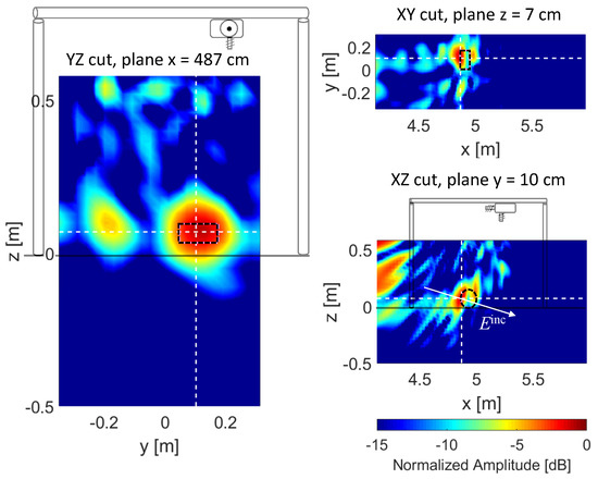
Figure 9.
Imaging results for the metallic can placed on the ground. GPR-SAR cuts are centered at the position of the target, the profile of which is highlighted with a black dashed line. The white arrow depicted in the XZ cut represents the direction of the incident field (−12° with respect to the horizontal plane). For reference purposes, the air–ground interface (z = 0 m) and a sketch of the layout of the portable setup are depicted in black color in the YZ and XZ cuts.
If Figure 8d and the XZ cut of Figure 9 are compared, it can be noticed that less clutter within the scanning area is observed in the latter. The reason is that 3D GPR-SAR processing is applied in Figure 9 (using all radar measurements), whereas GPR-SAR imaging results for only a single scan along the x-axis were presented in Figure 8d. Thus, clutter and noise present in the different scans along the x-axis are partially cancelled, whereas the echo due to the reflection on the metallic can is reinforced (added coherently).
As observed in Figure 7 and Figure 9, the imaging domain has been limited from y = −0.35 m to y = 0.32 m due to the fact that in this first validation test, sweeps along the y-axis were spaced 5 cm on average, which is greater than λ/2 at the highest working frequency (5 GHz) so aliasing appeared when considering x-axis sweeps outside the range from y = −0.35 m to y = 0.32 m. Concerning sweeps along the x-axis, samples were taken every 3.2 cm on average.
The range resolution provided by the hybrid FLGPR-DLGPR can be extracted from the GPR-SAR results depicted in Figure 9. The reflectivity −3 dB beamwidth along the incident field direction (denoted with a white arrow in Figure 9, XZ cut) is 7 cm, which is in agreement with the range resolution of the 2 GHz-bandwidth radar: ΔRange = c/(2 BW) = 7.5 cm, being c the speed of light, and BW the radar frequency bandwidth.
3.2. Testing Using a Buried Anti Tank Plastic Landmine
Next, the hybrid FLGPR-DLGPR system to detect shallow targets was tested. For this purpose, a model of non-metallic (plastic) anti-tank landmine was buried at 2–3 cm depth, as shown in Figure 10, resembling a realistic scenario. In this case, sweeps along the y-axis were spaced 3 cm to avoid aliasing. Only GNSS-RTK positioning information provided with the highest accuracy (fix operation mode) was considered, thus resulting in an acquisition domain ranging from y = −0.35 m to y = +0.18 m (RTK was not in fix operation mode for x-axis sweeps beyond y > +0.18 m due to the poor satellite coverage in the field where the experiments were performed).
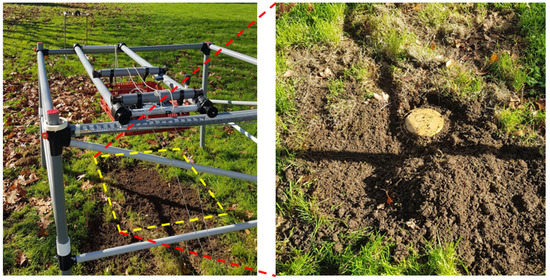
Figure 10.
Picture of the measurement setup with an anti-tank plastic landmine buried on the ground. A picture of the anti-tank landmine before burying it can be observed in the right picture.
GPR-SAR imaging results are shown in Figure 11. The echo due to the reflection on the buried plastic landmine is observed at z = −5 cm, slightly deeper than its true position since the soil permittivity is not taken into account (εr = 1 is used for GPR-SAR processing). Signal-to-clutter ratio can be estimated in 5 dB for both cases.
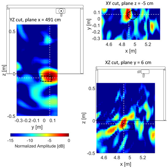
Figure 11.
Imaging results for the buried plastic landmine. GPR-SAR cuts are centered at the position of the target, the profile of which is highlighted with a black dashed line. For reference purposes, the air–ground interface (z = 0 m) and a sketch of the layout of the portable setup are depicted in black color in the YZ and XZ cuts.
For verification purposes, a second measurement of the plastic landmine buried at 2–3 cm depth has been conducted. This measurement consisted of a single linear sweep along the x-axis performed by manually displacing the receiving devices in 2-cm steps from x = 5 m to x = 6.30 m. The measurement setup is depicted in Figure 12: instead of using the portable setup [20], a simpler supporting structure was implemented to simplify the manual displacement of the platform containing the receiving devices. In this case, 2D GPR-SAR imaging is conducted (XZ plane, y = 0 cm).
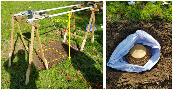
Figure 12.
Picture of a 2D-measurement setup (acquisition along x axis). A picture of the anti-tank plastic landmine can be seen in the right picture.
Imaging results are plotted in Figure 13, where the reflectivity peak corresponding to the buried landmine can be identified at about x = 5.7 m. As in the previous examples shown in this contribution, air–ground reflections are negligible. Inside the imaging domain, a high level of clutter can be noticed only around x = 5 m and x = 5.2 m (which might be due to reflections in the supporting wooden structure). Furthermore, the reflection happening in the rear wooden supporting structure can be noticed in Figure 13.
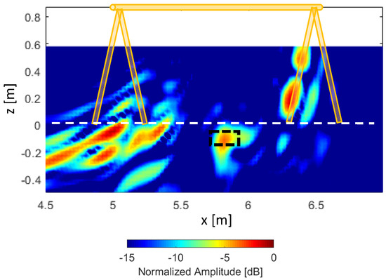
Figure 13.
Imaging results for the buried plastic landmine. The position of the buried plastic landmine is highlighted with a black dashed line, and the average position in the z axis of the surface of the ground is depicted with a white dashed line. The profile of the 2D-measurement setup has been superimposed.
4. Discussion
4.1. Quantitative Analysis
To complement the qualitative validation of the detection capabilities of the hybrid FLGPR-DLGPR system, a quantitative analysis based on a simplified propagation model is presented next. This quantitative analysis provides an estimation of the signal-to-clutter ratio at the receiver. In particular, the power reflected on the buried target (solid arrows, Figure 14) will be considered as the signal, and the power reflected on the ground due to specular reflection (dashed arrows, Figure 14) as the clutter. For the sake of simplicity, it will be considered that the main contribution of the field backscattered on the buried target will be normal to the soil–air interface, as depicted in Figure 14. The analysis has been performed considering both TE (Transverse Electric) and TM (Transverse Magnetic) polarizations.
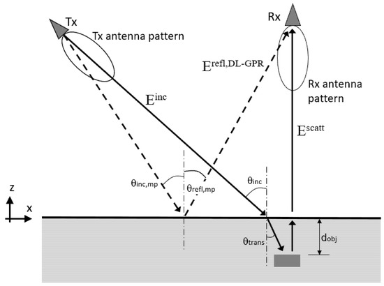
Figure 14.
Scheme of the propagation model analyzed in Section 4.1. z = 0 corresponds to the air–ground interface. The Rx antenna is located at x = 5 m, z = 1 m.
For this quantitative analysis, a metallic target will be considered, and the calculations will be conducted at the center frequency (f = 4 GHz) of the working frequency band.
The power transmitted by the radar module [22] is approximately −20 dBm, the gain of the transmitting and receiving helix antenna is G = 11 dB at 4 GHz and its directivity has been taken into account in the model. The soil constitutive parameters are: εr = 7 and σ = 0.02 S/m.
Three configurations will be analyzed. The first one (Table 1, second column) corresponds to a monostatic case where both the Tx and Rx antennas are located at x = 5 m. In the second case (Table 1, third column), the Tx antenna is located at x = 3 m. In the third case (Table 1, fourth column), the Tx antenna is located at x = 0 m, as in the examples presented in this contribution with the portable setup. In all the cases, the Tx and Rx antennas are placed at z = 1 m above ground (similarly to the examples presented in this contribution), and the receiver is located at x = 5 m. The metallic plate is considered to be buried 5 cm deep.

Table 1.
Quantitative analysis of monostatic DLGPR and hybrid FLGPR-DLGPR configurations. The definition of the terms listed in the first (left) column of the table is provided in the Appendix A.
From the quantitative analysis presented in Table 1 it can be concluded that:
- (1)
- The power backscattered by the buried plate is greater in the case of the DLGPR with respect to the hybrid FLGPR-DLGPR. This is consistent with the fact that propagation losses are smaller in the DLGPR system. Thus, targets buried deeper could be missed by the hybrid FLGPR-DLGPR as soil propagation losses would be larger.
- (2)
- The reflection at the air–ground interface is weaker in the case of the hybrid FLGPR-DLGPR, so that the contribution due to the reflection of the metallic plate will not be masked by the air–ground reflection. Note that, in the case of the DLGPR, the level of the contributions from the air–ground interface and from the buried metallic plate is similar, whereas in the proposed hybrid FLGPR-DLGPR the reflection from the buried plate is notably higher than the contribution due to specular reflection on the ground. This difference is also greater when considering TM polarization due to a low reflection coefficient at angles close to the Brewster’s angle.
4.2. Justification of the Applicability of the Hybrid FLGPR-DLGPR Architecture
As indicated in Section 1.2, the proposed hybrid FLGPR-DLGPR is devoted to detect shallow targets that could be masked by the air–ground reflection if DLGPR systems were used. In this sense, it is important to remark that anti-personnel landmines are shallowly buried (less than 5 cm), some being buried up to 15–20 cm [24,25]. Anti-tank mines are also buried not deeper than 20 cm [26,27]. Only in a few cases anti-tank mines and IEDS can be found at depths greater than 20 cm, resulting in a detection challenge even for DLGPR systems in case of wet soils (e.g., Table 2.3 of [28] shows that wet loamy soils can exhibit up to 600 dB/m losses at 1 GHz).
The issue of shallow targets masked by the air–ground reflection has been broadly discussed in the literature. In fact, as stated in [29], the air–ground reflection is the largest single source of clutter (including volumetric inhomogeneities such as rocks or roots, and surface vegetation). Despite this can be mitigated for deeply buried targets using time gating, it remains a challenge for shallowly buried ones, especially in the case of a rough ground surface. In this regard, although the usage of GPR systems for landmines and IEDs detection has several advantages, the antennas must be elevated above the ground in order to keep a safe distance, which results in a strong air–ground reflection [30]. Therefore, in these cases, especially when the buried targets are also small and present low dielectric contrast, it can be helpful to resort to alternative architectures, such as the hybrid FLGPR-DLGPR approach proposed in this contribution, to enhance the detection capabilities.
5. Conclusions
A hybrid FLGPR-DLGPR architecture has been implemented and validated successfully combining the advantages of FLGPR (minimization of the clutter due to air–ground reflections) and DLGPR (greater dynamic range and resolution).
Results presented in Section 3 confirm the capability of the implemented hybrid FLGPR-DLGPR architecture to detect shallowly buried objects, being supported by the discussion presented in Section 4 based on a quantitative analysis. In all the presented results clutter due to air-ground reflection within the scanning area is weaker than the reflection on the buried target, as the incident field on the ground within the scanning area is mainly reflected away from the DL-GPR Rx antenna.
The fact of using the 3 to 5 GHz frequency band makes the system more sensitive to geo-referring and positioning errors if compared to previous works where a DL-GPR radar and a sub-3 GHz frequency band were considered [17,20]. The reasons of using a higher frequency band were (i) the limited availability of multistatic wirelessly-synchronized radar modules, and (ii) the fact that this architecture was conceived to detect shallowly buried targets, so penetration depth capabilities were not as critical as in [17,20]. In these works, targets were buried deeper, so that the air–ground reflection characteristic of DL-GPR configurations did not mask the buried targets significantly. From the GPR-SAR imaging results depicted in [17,20], it can be noticed that the air–ground reflection resulted in a 6–8 cm thick strip, and the targets were buried more than 10 cm deep.
One of the key issues for the successful implementation of the system is the use of two radar modules that are synchronized without requiring physical connection between them. An additional receiving antenna pointing towards the transmitting antenna enabled perfect reception of the direct ray used by the receiving module for synchronization purposes. Signals captured by each receiving antenna could be easily filtered thanks to the addition of a delay line connected at the end of the receiving antenna pointing downwards.
A non-metallic plastic target (an anti-tank landmine) was selected for validation purposes, testing the performance of the system with a 2D setup (where the receiver is manually positioned) and with a 3D acquisition system (in which geo-referring information is provided by a GNSS-RTK module). In both cases, the buried target could be identified.
6. Patents
The work presented in this contribution is related to the patent “Airborne Systems and Detection Methods Localisation and Production of Images of Buried Objects and Characterisation of the Composition of the Subsurface”. Publication No. WO/2017/125627. International Application No. PCT/ES2017/000006. Priority date: 21 January 2016. International filing date: 18 January 2017. University of Oviedo, University of Vigo. European Patent EP3407007B1 granted on 30 September 2020. Available online: https://patentscope.wipo.int/search/en/detail.jsf?docId=WO2017125627 (accessed on 5 December 2020).
Author Contributions
Conceptualization, M.G.-F., Y.Á.L., and F.L.-H.A.; methodology, M.G.-F., Y.Á.L., and G.Á.-N.; software, M.G.-F., G.Á.-N. and Y.Á.L.; validation, all the authors; resources, all the authors; data curation, M.G.-F., G.Á.-N., and Y.Á.L.; writing—original draft preparation, Y.Á.L.; writing—review and editing, all the authors; supervision, F.L.-H.A. and Y.Á.L.; funding acquisition, F.L.-H.A. and Y.Á.L. All authors have read and agreed to the published version of the manuscript.
Funding
This research was funded by the Ministerio de Defensa—Gobierno de España and the University of Oviedo under Contract 2019/SP03390102/00000204 / CN-19-002 (“SAFEDRONE”); by the Xunta de Galicia–Axencia Galega de Innovación (GAIN) under project 2018-IN855A 2018/10 (“RadioUAV: drones para aplicaciones más allá de lo visible”); by the Government of the Principality of Asturias (PCTI) and European Union (FEDER) under Grant IDI/2018/000191; and by the Instituto Universitario de Tecnología Industrial de Asturias (IUTA) under Project SV-19-GIJON-1-17 (“RadioUAV”).
Acknowledgments
The authors would like to acknowledge the CIED-COE (Col. José Luis Mingote Abad and Br. Ramón Javier Pacheco) for their advice concerning the placement of the IEDs and landmines, and Cap. Santiago García Ramos for the supervision of the Contract 2019/SP03390102/00000204/CN-19-002 (“SAFEDRONE”), and also Carey M. Rappaport and Ann Morgenthaler for their previous contributions and advice in the theoretical study and analysis of this architecture, presented in publication [19].
Conflicts of Interest
The authors declare no conflict of interest.
Appendix A
Definition of the terms listed in the first (left) column of Table 1:
|ρair-ground|: module of the reflection coefficient at the air-ground interface in the path between the Tx antenna and the target.
|ρground-target|: module of the reflection coefficient at the ground-target interface.
|ρground-air|: module of the reflection coefficient at the ground-air interface (normal incidence is considered).
Prx,ant,Escatt: power received at the DL-GPR Rx antenna coming from the target, considering the Rx antenna gain.
|ρair-ground,mp|: module of the reflection coefficient at the air-ground interface at the specular reflection point.
Prx,ant,Erefl,DL-GPR: power received at the DL-GPR Rx antenna due to specular reflection on the ground, and considering the directive gain function of the Rx antenna.
SCR: signal-to-clutter ratio at the Rx antenna, defined as the ratio between Prx,ant,Escatt and Prx,ant,Erefl,DL-GPR. If positive, the power reflected in the buried plate is greater than the power contribution due to specular reflection at the air-ground interface.
References
- Jol, H.M. Ground Penetrating Radar Theory and Applications; Elsevier Science: Amsterdam, The Netherlands, 2009. [Google Scholar]
- Santos-Assunçao, S.; Perez-Gracia, V.; Caselles, O.; Clapes, J.; Salinas, V. Assessment of Complex Masonry Structures with GPR Compared to Other Non-Destructive Testing Studies. Remote Sens. 2014, 6, 8220–8237. [Google Scholar] [CrossRef]
- Morris, I.; Abdel-Jaber, H.; Glisic, B. Quantitative Attribute Analyses with Ground Penetrating Radar for Infrastructure Assessments and Structural Health Monitoring. Sensors 2019, 19, 1637. [Google Scholar] [CrossRef] [PubMed]
- Conyers, L.B. Ground-Penetrating Radar Mapping Using Multiple Processing and Interpretation Methods. Remote Sens. 2016, 8, 562. [Google Scholar] [CrossRef]
- De Chiara, F.; Fontul, S.; Fortunato, E. GPR Laboratory Tests for Railways Materials Dielectric Properties Assessment. Remote Sens. 2014, 6, 9712–9728. [Google Scholar] [CrossRef]
- Przemyslaw, K.; Godziuk, A.; Kapruziak, M.; Olech, B. Fast Analysis of C-Scans From Ground Penetrating Radar via 3-D Haar-Like Features With Application to Landmine Detection. IEEE Trans. Geosci. Remote Sens. 2015, 53, 3996–4009. [Google Scholar]
- Lombardi, F.; Lualdi, M.; Picetti, F.; Bestagini, P.; Janszen, G.; Di Landro, L.A. Ballistic Ground Penetrating Radar Equipment for Blast-Exposed Security Applications. Remote Sens. 2020, 12, 717. [Google Scholar] [CrossRef]
- Comite, D.; Ahmad, F.; Dogaru, T.; Amin, M.G. Adaptive Detection of Low-Signature Targets in Forward-Looking GPR Imagery. IEEE Geosci. Remote Sens. Lett. 2018, 15, 1520–1524. [Google Scholar] [CrossRef]
- Rosen, E.M.; Ayers, E. Assessment of Down-Looking GPR Sensors for Landmine Detection. In Proceedings of the SPIE, Orlando, FL, USA, 10 June 2005. [Google Scholar]
- Comite, D.; Galli, A.; Catapano, I.; Soldovieri, F. Advanced imaging for down-looking contactless GPR systems. In Proceedings of the International Applied Computational Electromagnetics Society Symposium—Italy (ACES), Florence, Italy, 26–30 March 2017. [Google Scholar]
- Zhang, Y.; Orfeo, D.; Burns, D.; Miller, J.; Huston, D.; Tian, X. Buried nonmetallic object detection using bistatic ground penetrating radar with variable antenna elevation angle and height. In Nondestructive Characterization and Monitoring of Advanced Materials, Aerospace, and Civil Infrastructure; SPIE Proceedings: Portland, OR, USA, 2017; Volume 10169. [Google Scholar] [CrossRef]
- Kimata, T.; Shigematsu, K.; Nakajima, H.; Morita, J. Detection of the buried landmine/projectile using LS-band FLGPR vehicle. In Proceedings of the SPIE Defense + Commercial Sensing, Baltimore, ML, USA, 14–18 April 2019. [Google Scholar]
- Comite, D.; Ahmad, F.; Dogaru, T.; Amin, M. Coherence-Factor-Based Rough Surface Clutter Suppression for Forward-Looking GPR Imaging. Remote Sens. 2020, 12, 857. [Google Scholar] [CrossRef]
- Colorado, J.; Perez, M.; Mondragon, I.; Mendez, D.; Parra, C.; Devia, C.; Martinez-Moritz, J.; Neira, L. An integrated aerial system for landmine detection: SDR-based Ground Penetrating Radar onboard an autonomous drone. Adv. Robot. 2017, 31, 791–808. [Google Scholar] [CrossRef]
- Schreiber, E.; Heinzel, A.; Peichl, M.; Engel, M.; Wiesbeck, W. Advanced Buried Object Detection by Multichannel, UAV/Drone Carried Synthetic Aperture Radar. In Proceedings of the 2019 13th European Conference on Antennas and Propagation (EuCAP), Krakow, Poland, 31 March–5 April 2019; pp. 1–5. [Google Scholar]
- Šipoš, D.; Gleich, D. A Lightweight and Low-Power UAV-Borne Ground Penetrating Radar Design for Landmine Detection. Sensors 2020, 20, 2234. [Google Scholar] [CrossRef] [PubMed]
- García-Fernández, M.; López, Y.Á.; Andrés, F.L.-H. Airborne Multi-Channel Ground Penetrating Radar for Improvised Explosive Devices and Landmine Detection. IEEE Access 2020, 8, 165927–165943. [Google Scholar] [CrossRef]
- Schartel, M.; Burr, R.; Bähnemann, R.; Mayer, W.; Waldschmidt, C. An experimental study on airborne landmine detection using a circular synthetic aperture radar. arXiv 2020, arXiv:2005.02600. Available online: http://arxiv.org/abs/2005.02600 (accessed on 7 December 2020).
- Garcia-Fernandez, M.; Morgenthaler, A.; Alvarez-Lopez, Y.; Las Heras, F.; Rappaport, C. Bistatic Landmine and IED Detection Combining Vehicle and Drone Mounted GPR Sensors. Remote Sens. 2019, 11, 2299. [Google Scholar] [CrossRef]
- García-Fernández, M.; Álvarez López, Y.; De Mitri, A.; Castrillo Martínez, D.; Álvarez-Narciandi, G.; Las-Heras Andrés, F. Portable and Easily-Deployable Air-Launched GPR Scanner. Remote Sens. 2020, 12, 1833. [Google Scholar] [CrossRef]
- Garcia-Fernandez, M. Novel Measurement System Based on Electromagnetic Sensors on Board Unmanned Aerial Vehicles for Subsurface Imaging and Antenna Measurement Applications. Ph.D. Thesis, University of Oviedo, Gijón, Spain, 2019. [Google Scholar]
- P-440 Ultra Wideband (UWB) Radio Transceiver. Available online: https://usermanual.wiki/Humatics/P440A/pdf (accessed on 1 December 2020).
- Topcon B111 Receiver. Available online: https://www.topconpositioning.com/oem-components-technology/gnss-components/b111 (accessed on 1 December 2020).
- Keeley, R. Understanding Landmines and Mine Action. September 2003. Available online: http://web.mit.edu/demining/assignments/understanding-landmines.pdf (accessed on 23 January 2021).
- Marble, J.A.; Yagle, A.E. Measuring Landmine Size and Burial Depth with Ground Penetrating Radar. In Proceedings of the SPIE Defense and Security, Orlando, FL, USA, 13–15 April 2004. [Google Scholar]
- Walls, R.; Brown, T.; Clodfelter, F.; Coors, J.; Laudato, S.; Lauziere, S.; Patrikar, A.; Poole, M.; Price, M. Ground penetrating radar field evaluation in Angola. In Proceedings of the SPIE Defense and Security Symposium, Orlando, FL, USA, 17–21 April 2006. [Google Scholar]
- Geneva International Centre for Humanitarian Demining (GICHD) and Stockholm International Peace Research Institute (SIPRI). The Humanitarian and Developmental Impact of Anti-Vehicle Mines. Geneva, September 2014. Available online: https://www.gichd.org/en/resources/publications/detail/publication/the-humanitarian-and-developmental-impact-of-anti-vehicle-mines/ (accessed on 23 January 2021).
- Daniels, D.J. Ground Penetrating Radar, 2nd ed.; The Institution of Electrical Engineers: London, UK, 2004; ISBN 9780863413605. [Google Scholar] [CrossRef]
- Rappaport, C.M.; El-Shenawee, M.; Zhan, H. Suppressing GPR Clutter from Randomly Rough Ground Surfaces to Enhance Nonmetallic Mine Detection. Subsurf. Sens. Technol. Appl. 2003, 4, 311–326. [Google Scholar] [CrossRef]
- Feng, X.; Sato, M.; Zhang, Y.; Liu, C.; Shi, F.; Zhao, Y. CMP Antenna Array GPR and Signal-to-Clutter Ratio Improvement. IEEE Geosci. Remote Sens. Lett. 2009, 6, 23–27. [Google Scholar] [CrossRef]


Publisher’s Note: MDPI stays neutral with regard to jurisdictional claims in published maps and institutional affiliations. |
© 2021 by the authors. Licensee MDPI, Basel, Switzerland. This article is an open access article distributed under the terms and conditions of the Creative Commons Attribution (CC BY) license (http://creativecommons.org/licenses/by/4.0/).