Abstract
In this research, an effective application and performance assessment of the Neuro-Fuzzy Controller (NFC) damping controller is designed to replace a single machine infinite bus (SMIB) power system stabilizer (PSS), and coordinated multi PSSs in large interconnected power systems are presented. The limitation of the conventional PSSs on SMIB and interconnected multi-machine test power systems are exposed and disclosed by the proposed NFC stabilizer. The NFC is a nonlinear robust controller which does not require a mathematical model of the test power system to be controlled, unlike the conventional PSSs’ damping controller. The Proposed NFC is designed to improve the stability of SMIB, an interconnected IEEE 3-machine, 9-bus power system, and an interconnected two-area 10-machine system of 39-bus New England IEEE test power system under multiple operating conditions. The proposed NFC damping controller performance is compared with the conventional PSS damping controller to confirm the capability of the proposed stabilizer and realize an improved system stability enhancement. The conventional PSSs’ design problem is transformed into an optimization problem where an eigenvalue-based objective function is developed and applied to design the SMIB-PSS and the interconnected multi-machine PSSs. The time-domain phasor simulation was done in the SIMULINK domain, and the simulation results show that the transient responses of the system rise time, settling time, peak time, and peak magnitude were all impressively improved by an acceptable amount for all the test system with the proposed NFC stabilizer. Thus, the NFC was able to effectively control the LFOs and produce an enhanced performance compared to the conventional PSS damping controller. Similarly, the result validates the effectiveness of the proposed NFC damping controller for LFO control, which demonstrates more robustness and efficiency than the classical PSS damping controller. Therefore, the application and performance of the NFC has appeared as a promising method and can be considered as a remarkable method for the optimal design damping stabilizer for small and large power systems.
1. Introduction
During power system operation, several undesired phenomena, such as disturbance, may affect the system response, which can render the system vulnerable to instability [1,2]. Low-frequency oscillations (LFOs) are among many instability agents which cause the electromechanical modes (EMs) damping of sustained power system oscillations to reside in the system, leading to a loss of synchronism [3]. Power system LFOs were initially discovered in the early 60s in the large, coordinated and interconnected Northern USA power system, in the tentative North-South power lines tie line [4]. Moreover, the WSCC interconnected power system of the two countries (the USA and Canada) underwent a brownout in August of 1996 because of undamped LFOs that left millions of customers in shutdown, with an approximately 30,500 MW lost in the grid [4]. Other blackouts due to LFOs were the UK 0.5 Hz frequency oscillation of 1980, the Taiwan 0.78–1.05 Hz LFO in 1984, 1989, 1990, 1991, and 1992, the Scandinavia 0.5 Hz LFO of 1997, the China 0.4 Hz LFO blackout of 2003, the USA 0.17 Hz LFO of 2003, the Italian 0.55 Hz LFO of 2003, and many more [4].
LFOs with a 0.2 to 3 Hz frequency array are one of the penalties of interconnected power networks [5]. They are outcomes of LFOs between interconnected generators of an area associated with those of the neighboring areas [6]. LFOs in power systems are commonly exhibited with a small ordinary system load variation, which later intensifies, predominantly for a severe unforeseen event [7]. In a deficiency of sufficient damping, they will reside and may cause the interconnected power system to lose its synchronism. Alternatively, they may stop the system connection between the two nearby areas, thus impelling the utilization of the transmission lines size and the overall system stability [8]. Hence, it becomes obligatory to control LFOs to retain system stability.
To increase the LFO damping properties and intensify the power system oscillation stability, an automatic voltage regulator (AVR) only in the generator excitation system is not sufficient [9]. Thus, the utilities furnished the exciter with an additional supplementary control which is simple in structure: an effective and economical system called power system stabilizer (PSS). Conventional PSS is one of the many key power system pieces of machinery which have been broadly employed to suppress LFOs in the course of eventualities and improve system stability [10].
Mostly, the conventional PSS is a permanent parameter type operating under a particular system operating condition, and its parameters were acquired through trial and error. They have a substantial impact on its performance and may fail to successfully suppress the LFO in the system. Conventional PSS parameter design is a burdensome implementation, and many mathematical methods were proposed in the literature, such as the eigenvalue method, gradient methods for optimization, numerical programming method, robust control method, method, and so on [11,12]. However, it was shown that, for the design of PSS for large interconnected multi-machine power systems operating on different operating conditions and structures, mathematical approaches take a long time to evaluate the system’s mathematical models, and the optimum PSS design is from time to time incorrect [13,14,15]. Another constraint with these methodologies is that they are incapable of reaching an inclusive solution [16,17]. It is generally difficult to find real-time robust controller parameters with traditional tuning controller techniques because of the volume and dynamical nature of the power system.
Currently, intelligent metaheuristic tuning methods have developed, and their application has increased due to its advantage in solving difficult high-dimension, non-linear, non-differentiable, non-convex, and multi-modal real-world problems [18,19]. Many of these methods are employed for single machine infinite bus (SMIB) and multi-machine PSSs parameter design, such as Evolutionary Programming (EP) [20], Differential Evolution (DE) [21], Genetic Algorithm (GA) [22], Particle Swarm Optimization (PSO) [23], Whale Optimization Algorithm (WOA) [24], Salp Swarm Algorithm (SSA) [25], Kidney-inspired Algorithm (KA) [13], Grasshopper Optimization Algorithm (GOA) [16], Bacteria Foraging Optimization (BF) [26], Sine Cosine Algorithm (SCA) [27], Bat Algorithm (BA) [28], Cuckoo Search Optimization (CSO) [29], Artificial Bee Colony (ABC) [30], General Relativity Search Algorithm (GRSA) [31] etc. These algorithms offer good a performance as regards the problem of PSS design. Nevertheless, when the optimization objective function is multimodal with a high dimension, then the overall optimal solution can have a substantial impact, and the solution may be limited in local optimum points. Hence, the optimal design of interconnected multi-machine PSSs for highly nonlinear power systems under different system operating conditions is still required for a healthy system operation.
Another limitation with these approaches is that they are unable to reach a global solution [32]. It is usually hard to find online optimal controller parameters with classical tuning controller methods, due to the complexity and dynamical nature of the system. Moreover, the conventional PSSs are in many cases designed for the damping of local mode oscillations and not inter-area mode oscillations [33]. Therefore, to satisfy the necessity of an excitation control system and escape the rising difficulty encountered by conventional PSS control schemes, Artificial Intelligence (AI) controllers have been widely developed these days [34]. In [35], a neural observer PSS with a doubly fed induction generator (DFIGs) was developed to improve the system damping and low-voltage ride-through capability. The coordination of adaptive neuro-fuzzy interface system (ANFIS) and type-2 fuzzy system PSS (T2FLS-PSS) was combined to improve a large-scale 39-bus, 10 machine power system in [36]. Furthermore, a new method for a novel fuzzy neural-PI-controller-based static synchronous series compensator (SSC) and a fuzzy-PSS with a novel structure were simultaneously developed in [37] for damping the power system oscillation on a 4-machine, 2-area, and 3-machine, 3-area power system. Another novel fuzzy rule matrix was designed in [38] for fuzzy logic system PSS to effectively damp the low-frequency oscillations of a SMIB and 2-area, 4-machine, 10-bus power system.
In this work, a robust and nonlinear AI controller called Neuro-Fuzzy Controller (NFC), which does not require a mathematical model of the SMIB, and interconnected multi-machine test power systems to be controlled were designed to replace the power system stabilizer (PSS) damping controller, in order to improve the stability of the test systems and offset the low-frequency oscillations (LFOs) for a system operating under multiple operating conditions. The design of an NFC stabilizer in place of the conventional PSS installed in the test power systems that do not require the mathematical model of the test power system to be controlled is a difficult task, and it is the motivation and contribution in this research. The designed NFC has two inputs, six outputs, and six layers. The performance of the proposed NFC stabilizer was tested on SMIB, an interconnected IEEE 3-machine, 9-bus WSCC power system, and an interconnected two-area 10-machine system of a 39-bus New England IEEE test power system. An eigenvalue simulation analysis and nonlinear time-domain simulation works were performed in a MATLAB/SIMULINK environment to investigate the effectiveness of the proposed NFC stabilizer as compared to the conventional PSS optimization method.
A comparison is made between the performance of the test system with a conventional PSS damping controller and the test system with the proposed NFC damping controller in a MATLAB/SIMULINK environment. The NFC has been employed to improve the test power system damping properties. For the proposed NFC damping controller, results were found to be able to develop the unstable modes as the system realizes stability with small overshoot. Section 2 presents the system model studies with the NFC stabilizer and the FFA-PSS, while Section 3 and Section 4 explain the research results and conclusions, respectively.
2. Model of the Interconnected Power System
Differential-Algebraic Equations (DAEs) define the test system model dynamism. The synchronous machine differential equations and the automatic voltage regulator (AVR) [39] are defined by the following equations:
where the generator rotor angle is , the generator speed is , the synchronous speed is , the internal transient voltage is and . They are behind and , which are the d-axis and q-axis transient reactances, respectively. and are the d-axis and q-axis constituents of the generator stator currents, respectively, the damping coefficient is , the mechanical power input is , the generator inertia constant is , the d-axis and q-axis reactance is and , respectively, while and are the open circuit d-axis and q-axis time variable constants, respectively. is the terminal voltage for the synchronous generator, while the exciter voltage is , the regulator gain is , the regulator time constant is and the regulator reference voltage is . In Equations (1) and (4), i represents the synchronous generator.
To simplify the excitation controller design, we consider the mechanical input torque as a constant term, meaning we make an assumption here that the governor action is so slow that its impact is insignificant on the system dynamics [31]. Now the electrical torque is expressed as:
The electrical torque is introduced in Equation (4). For a power system having buses and generators, it provides load buses. Then, the algebraic power system equations can be represented by:
where the active and reactive powers are and , respectively, the admittance matrix is and the bus voltage angle is . Constant impedances in a power system having generators represent the loads. The basic terms and definitions related to linear system analysis, along with the linearization method of nonlinear systems out of the DAEs from Equations (1)–(9), are explained below:
Using a set of first-order nonlinear DAEs, system behavior can be represented as follows:
where is the set of the first-order nonlinear differential equations that represent the system and the controller dynamics, is the vector of the state variables, represents the vector of the algebraic variables, is the vector of the input variables, is the set of nonlinear algebraic equations that describes the network power flow equations, is a set of output variables, and is the set of equations that represents the output variables. In this study, represents the vector of the bus voltage magnitudes and phase angles, represents the PSS output signals. , where, and are the rotor angles and rotor speed, respectively, while and are the internal and field voltages, respectively.
The design of the PSS is based on the linear incremental model and on [40,41], while the linearized power system model with machines and PSSs around an equilibrium point is given as follows:
where , , , , , , , ,
Now, eliminating and assuming that the power flow Jacobian is non-singular, the state space equation of the system can be readily written as follows:
where and are and matrices, respectively, given by Equation (15).
The output variables can be written as Equation (16).
where and are
This method of presenting the power system with DAEs is extensively used for power system small signal stability analysis.
2.1. PSS Design Procedure
A wide speed based shown in Figure 1 is utilized in this research [42]. The conventional PSS can be represented by the transfer function of the system in Equation (18), as shown in Figure 1.
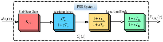
Figure 1.
Conventional power system stabilizers (PSS) system structure.
Here, is the stabilizing signal from the conventional PSS output at the machine, is called the time constant from the washout block, is the mechanical speed deviation signal from the synchronous speed of the machine. The PSS parameters to be determined here are the stabilizer gain and the and respectively. These PSS parameters are tuned using a Farmland Fertility Algorithm (FFA). Figure 2 shows the conventional PSS system connected to the IEEE-type-ST1 excitation system.
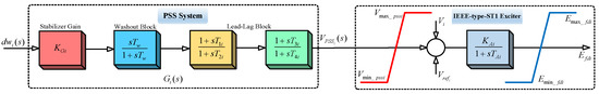
Figure 2.
Conventional PSS system connected to IEEE-type-ST1 excitation system.
2.2. Design and Implementation of the Neuro-Fuzzy Controller
NFC was designed and successfully applied to many industrial applications that work on the principle of employing Artificial Neural Network (ANN) constructively to execute the function of the Fuzzy Logic Controller (FLC) [34]. The FLC is capable of making inferences from expert knowledge, and the ANN has the capability of learning, generalizing, and adapting. The NFC is an intelligent control system combining the qualities of the FLC and ANN. Therefore, NFCs show characteristics of a nonlinear controller that is capable of learning, adapting, and making inferences. The NFC is considered to be one of the controllers suitable for model-free design. These properties make the NFC robust when associated with other conventional controllers. Consequently, NFCs are commonly used in non-linear systems with parameter variation and uncertainty. Consider the Fuzzy rules of the Sugeno type Fuzzy logic defined below:
where Xi and y are the input and output variables, respectively, and Aij ϵ R are the coefficients of the linear fi = (x1, x2… xn) function. The schematic structure of the NFC that is employed in the control algorithm is shown in Figure 3.
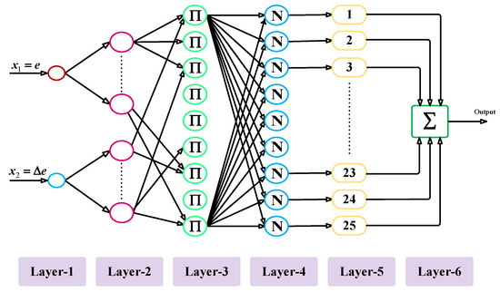
Figure 3.
Two-input Sugeno type neuro-fuzzy controller (NFC) structure.
The inputs of the NFC are error (e) and change in error (∆e). The five membership functions were chosen for each input [43]. It can be seen that membership functions are executed in the second layer. In this case, the membership function is substituted by an activation function for each artificial neuron. The output of this layer is as follows:
where σ and m are also input parameters that represent the parameters of membership functions to be adapted. Xi is the input of the ith cell of the 2nd layer. Similar to FLC, the third layer of NFC consists of a rule base, and Fuzzy rules are determined in this layer.
where Xj3 is the input of the jth cell of the third layer. The output of the system is defined using central clarification for Mamdani Fuzzy logic, as shown below:
where layer-4 is called the normalization layer, in which the accuracy of Fuzzy rules is calculated. Layer-5 is called the firing size of a rule. The firing degree of normalized rules is multiplied by the linear f function in this layer. This layer generates the output values required for the interconnected test system.
The output of layer-6 is as follows:
To update input and output parameters by using the analog teaching method with the backpropagation algorithm, the squared error (E) which minimizes tracking error (e) is determined as follows [44]:
The parameters to be adapted can be updated by the following equation:
Here, is the parameter to be adapted and is the learning rate. The chain rule is used to obtain the partial derivative. The derivative chain up to the output of the NFC is obtained from the following equation:
where the local gradient is . Updating the result parameters of the NFC used in the interconnected test system was achieved as follows:
In the NFC structure, precondition parameters of the membership layer have been trained in the simulation model. During the simulation studies, outcome parameters have been trained using a back-propagation learning algorithm. The complete structure of the NFC damping controller-based interconnected test power system is shown in Figure 4. To control the LFO in the system, the synchronous rotor speed deviation is applied to the NFC controller. A reference value for NFC signal is obtained from the output of the NFC controller. These voltage signals are sent to the excitation system block, which generates the required signals for damping the LFOs in the test system.
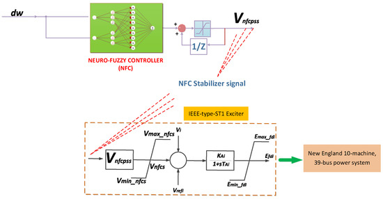
Figure 4.
New England 10-machine test power system equipped with NFC stabilizers.
Table 1 shows the suitable choice of parameters used for the FFA algorithms, which help the algorithms achieve optimal convergence speed and a fast computational cost for the PSS design [45]. The optimization process was terminated by a pre-specified number of iterations for all the three algorithms, and it is worth mentioning that the PSS design method was initialized and run several times before the optimal parameters of the PSS were chosen [46].

Table 1.
Search parameter settings for the Farmland Fertility Algorithm (FFA).
3. Results and Discussion
This section discusses the eigenvalue, time-domain, and transient response simulation results of the three test power systems under multiple operating conditions.
3.1. SMIB Power System Results and Discussion under Operating Condition 1
The SMIB power system structure used was modeled in the SIMULINK domain with the following system parameters, and the complete system data can be found in [40]. The SMIB synchronous generator is represented by fourth-order models of the DAEs explained by the test system modeling equations described earlier. In this research, MATPOWER software was utilized to execute the system power flow which computes the system’s initial condition states. The solution of the DAE Equations (1)–(9) shows the power system’s nonlinear dynamic behavior and the DAEs are solved via an ODE solver in MATLAB/SIMULINK.
3.1.1. Time-Domain Simulation of the SMIB Test Power System without PSS and NFC Damping Controllers under Operating Condition 1
In this section, the system undergoes a disturbance without a damping controller (PSSs and NFC) for LFO mitigation, and hence system stability enhancement. Eigenvalues simulation analysis and nonlinear time-domain simulations should be conducted for comprehensive evaluation. The SMIB system was subjected to a three-phase fault without a PSS damping controller. A symmetrical 100 ms three-phase fault was observed at and a nonlinear time-domain simulation was performed. After the fault was cleared, at 0.2 s, the system stable condition was restored.
Table 2 shows the eigenvalues results with their associated damping ratio and the frequency for the power system case without the PSS and NFC installed. From Table 2, Mode 1 produces a weak damping ratio for the no PSS case condition with eigenvalues. Similarly, the worst damping ratio of EM was found to be .
Table 2.
SMIB power system eigenvalues, damping ratio, and frequency of the EMs without PSS and NFC.
In addition, a nonlinear time-domain simulation was performed, and Figure 5 shows the unstable generator relative power angles δ in radian for the system without PSS and NFC, while Figure 6 shows the unstable generator speed deviation in radian per second for the system without PSS and NFC. Similarly, Figure 7 shows the unstable system rotor speed response in radian per second for the system without PSS and NFC.
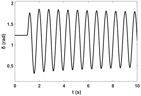
Figure 5.
Unstable power angle response for the system without PSS and NFC.
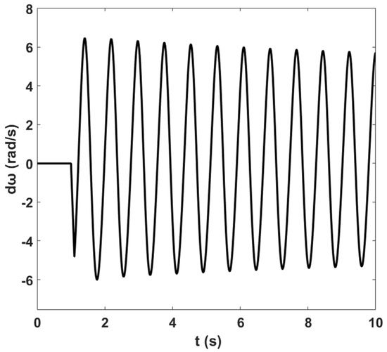
Figure 6.
Unstable rotor speed deviation response for the system without PSS and NFC.
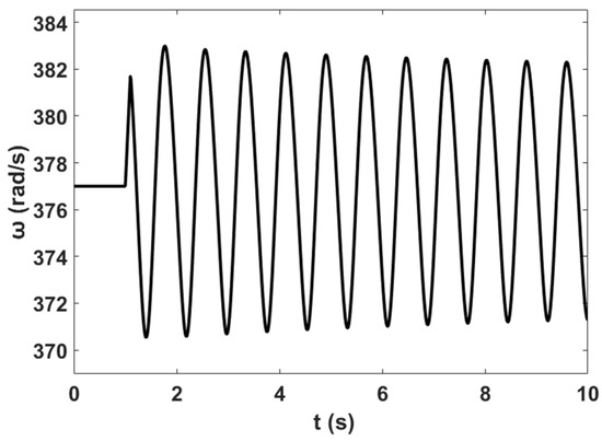
Figure 7.
Unstable rotor speed response for the system without PSS and NFC.
3.1.2. Time-Domain Simulation of the SMIB Test Power System with PSS Damping Controller under Operating Condition 1
For the PSS stabilizer design, a symmetrical 100 ms three-phase fault was observed at and a nonlinear time-domain simulation was performed. To increase the damping properties of the electromechanical modes (EMs), there are two types of objective function used for the optimization process: the eigenvalue-based objective function Equation (29), which is employed to prevent unstable modes formation that will lead the system’s eigenvalues to move towards the left-hand side (LHS) of the complex plane, and the time-domain-based objective function. In this study, the damping properties of the electromechanical modes (EMs) were improved using an eigenvalue-based objective function in Equation (30), where the PSS control parameters can be determined by solving the system state matrix from Equation (14).
where represents the eigenvalues of the power system state matrix from Equation (14), is a constant called the penalty constant, that is applied in forming the positive eigenvalues (and can also improve the slow eigenvalues) and was considered to be 50 in this study. The objective function minimizes the inter-regional and EM system damping, while at the same time preventing unstable modes formation that will lead the system’s eigenvalues to move towards the left-hand side (LHS) of the complex plane. The typical values of the optimized parameters of the PSS gain are 1 ≤ KGi ≤ 6 and 0.1 ≤ T1i ≤ 1, 0.001 ≤ T2i ≤ 0.01, 0.1 ≤ T3i ≤ 1, 0.001 ≤ T4i ≤ 0.01 for the time constants of the PSS. Moreover, the value of the washout time constant is commonly fixed and chosen as (Beiranvand and Rokrok, 2015). The proposed novel FFA optimizer computes the optimization problem and searches the optimum values of PSS parameters .
The rate at which the PSS design index converges using the FFA search algorithm is shown in Figure 8, while the optimal parameters of the designed PSSs are shown in Table 3. From the convergence characteristics, the FFA method shows a good convergence rate at eight iterations.
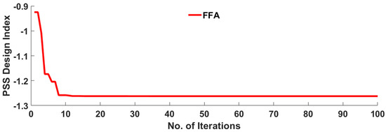
Figure 8.
Convergence characteristics of FFA in finding optimal design of PSS.
Table 3.
Optimal PSS parameters using the FFA search algorithm.
Table 4 shows the eigenvalues results with their associated damping ratio and the frequency for the power system case with PSS installed in the system, respectively. From Table 2, Mode 2 produces a weak damping ratio for the no PSS case condition. After the optimal PSS design, these modes were impressively enhanced from up to a stable mode of respectively, using the FFA design method. Similarly, the worst damping ratio EM was improved from to using the FFA design method. Similarly, Figure 9 illustrates the eigenvalues plot for the system with the FFA-PSS controller based on the numerical simulation results of Table 2 and Table 4.
Table 4.
SMIB test power system eigenvalues and their related damping ratios of the EMS for FFA PSS design algorithms.
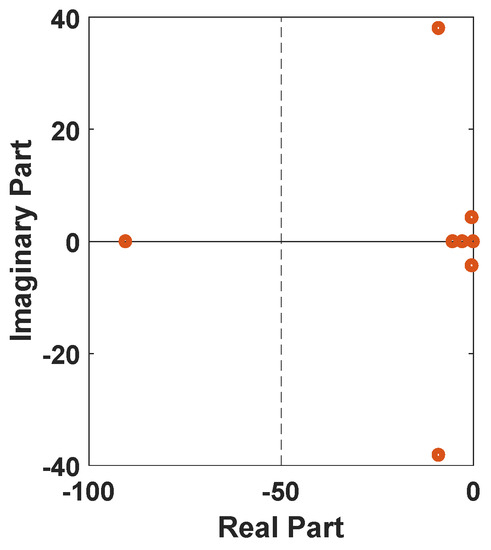
Figure 9.
Eigenvalues plot for the system with the FFA-PSS damping controller.
Moreover, a nonlinear time-domain simulation was performed, and Figure 10 shows the stable generator relative power angles δ in radian for the system with PSS, while Figure 11 shows the stable generator speed deviation in radian per second for the system with PSS. Similarly, Figure 12 shows the stable system rotor speed response in radian per second for the system with PSS.
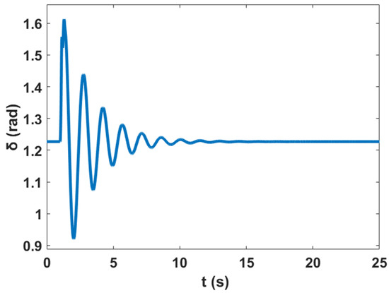
Figure 10.
Stable power angle response for the system with PSS.
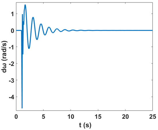
Figure 11.
Stable rotor speed deviation response for the system with PSS.
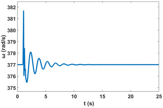
Figure 12.
Stable rotor speed response for the system with PSS.
3.1.3. Time-Domain Simulation of the SMIB Test Power System with NFC Damping Controller under Operating Condition 1
In this case, the test power system is equipped with an NFC stabilizer, and a symmetrical three-phase fault is subjected to the system. Table 5 shows the eigenvalues results with their associated damping ratio and frequency for the power system case with NFC installed in the system, respectively. From Table 2, Mode 2 produces a weak damping ratio for the no PSS case condition. After the NFC design, these modes were impressively enhanced from up to a stable mode of respectively, using the NFC stabilizer. Similarly, the worst damping ratio EM was improved from to using the NFC. Similarly, Figure 13 illustrates the eigenvalues plot for the system with the NFC stabilizer controller based on the numerical simulation results of Table 2 and Table 5.
Table 5.
SMIB Test power system eigenvalues and their related damping ratios of the EMs for the NFC damping controller.
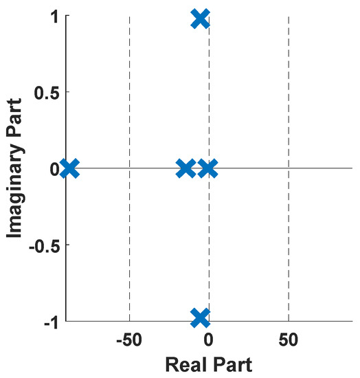
Figure 13.
Eigenvalues plot for the system with the NFC damping controller.
Moreover, a nonlinear time-domain simulation was performed with NFC installed in the system, and Figure 14 shows the stable generator relative power angles δ in radian for the system with NFC, while Figure 15 shows stable the generator speed deviation in radian per second for the system with NFC. Similarly, Figure 16 shows the stable system rotor speed response in radian per second for the system with NFC.
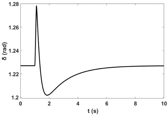
Figure 14.
Stable power angle response for the system with NFC.
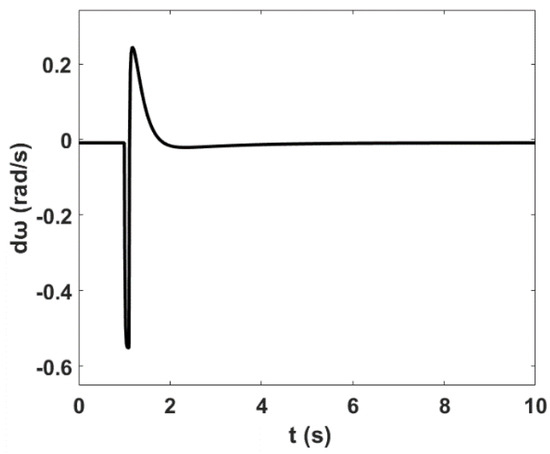
Figure 15.
Stable rotor speed deviation response for the system with NFC.
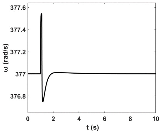
Figure 16.
Stable rotor speed response for the system with NFC.
3.1.4. Comparison between the Proposed NFC and PSS Damping Controllers under Operating Condition 1
This section presents comparative simulation results between the proposed NFC and the PSS damping controllers for LFO’s robustness. The generator power angles δ in radian, the generator rotor speed deviation in radian per second for the SMIB system using PSS, and the proposed NFC damping controllers are shown in Figure 17 and Figure 18 respectively.
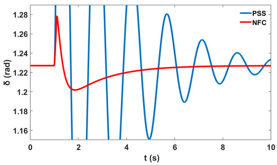
Figure 17.
Power angle response for the single machine infinite bus (SMIB) system.
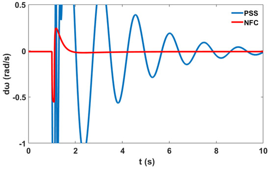
Figure 18.
Rotor speed deviation response for the SMIB system.
Similarly, Figure 19 shows the variation in the generator speed in radian per second for the SMIB system for PSS and the proposed NFC stabilizer.
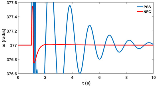
Figure 19.
Rotor speed response for the SMIB system.
From the time-domain simulation results, it was seen that the stabilizer using the proposed NFC was effectively able to damp out the LFOs of the test system under severe system disturbances. Thus, the NFC damping controller can be applied as a general damping controller for the robust design stabilizer and other similar science and engineering controller applications.
3.1.5. Response Scenario for Controller Performance Analysis under Operating Condition 1
This section explains the transient response simulation which describes the performance analysis of the SMIB power system when the system has no controller (NC), with a PSS controller, and with the proposed NFC damping controller for the SMIB system, respectively. Table 6 considers how the SMIB system responds to the transient situation with respect to settling time (ST), rise time (RT), peak time (PT), and peak magnitude (PM) for NC, PSS, and NFC damping controller cases, respectively. The rotor speed (ω) SMIB transient response in terms of settling time and rise time were all remarkably improved by an amount of 73.21% and 87.02%, respectively, by the proposed NFC stabilizer as compared with the NC in the system.
Table 6.
SMIB System Performance.
The NFC controller’s transient simulation analysis was found to be able to improve the system stability in terms of ST, RT, PT, and PM by an acceptable amount, when compared with the PSS, and thus to damp out the LFOs under credible contingency. Nonetheless, the minimum control effort of the NFC damping controller showed its effectiveness to control LFOs and thereby enhance the overall dynamic stability of the SMIB system, as compared to the application of the PSS damping controller.
3.2. WSCC 3-Machine Test Power System Results and Discussion under Operating Condition 1
This section of the work considered the familiar Western System Coordinated Council (WSCC) 3-machine 9-bus power system. The single line configurations of the power system are as shown in Figure 20, and the complete system data can be found in [31]. The dynamic stability of the WSCC test system can be obtained considering generator G1 (which is the slack bus) as the reference generator, which is not equipped with the PSSs. The interconnected synchronous generators are represented by fourth-order models of the DAEs explained by the test system modeling equations described earlier.
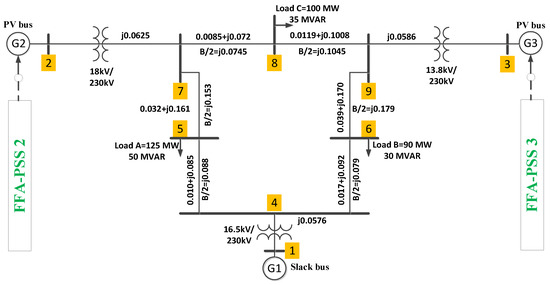
Figure 20.
Western System Coordinated Council (WSCC) 3-machine power system single line structure with FFA-PSS design algorithm.
A complete simulation model of all systems was designed in MATLAB/Simulink software. The Simulink model of the complete system is depicted in Figure 21. Furthermore, the simulation parameters related to this model can be found in [26].
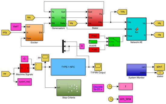
Figure 21.
Simulink model of complete WSCC test power system equipped with NFC.
The performance of the proposed NFC stabilizer was assessed for three different operating conditions, taking into account criteria such as settling time (ST), rise time (RT), peak time (PT), and peak magnitude (PM). The operating conditions are given below.
- ➢
- Condition-1: contingency at bus 9 with no change in the system loading.
- ➢
- Condition-2: contingency at bus 9 with a 120% increase in active power on generator 2 and generator 3.
- ➢
- Condition-3: contingency at bus 9 with an 80% decrease in active power on generator 2 and generator 3.
3.2.1. Time-Domain Simulation of the 3-Machine Test Power System without PSS and NFC Damping Controllers under Operating Condition 1
In this section, the system undergoes a disturbance without a damping controller (PSSs and NFC) for LFOs mitigation, and hence system stability enhancement. An eigenvalues simulation analysis and nonlinear time-domain simulations should be carried out for comprehensive evaluation. The test system was subjected to a three-phase fault without a PSS damping controller. A symmetrical 100 ms three-phase fault was observed at and a nonlinear time-domain simulation was performed. After the fault was cleared, at 0.2 s, the system’s stable condition was restored. Table 7 shows the eigenvalues results with their associated damping ratio and frequency for the power system case without the PSS and NFC installed. From Table 7, Mode 1 and Mode 2 produce a weak damping ratio for the no PSS case condition with and eigenvalues. Similarly, the worst damping ratio EM was found to be and respectively.
Table 7.
WSCC interconnected power system eigenvalues, damping ratio, and frequency of the EMs without PSS and NFC.
In this section, the system undergoes a disturbance without PSSs and NFC damping controller for LFOs mitigation, and hence system stability enhancement. A nonlinear time-domain simulation was performed, and Figure 22 shows the unstable generator power angles δ relative to in radian for the interconnected test power system for the operating condition 1 while Figure 23 shows the unstable generator speed deviation in radian per second for the system without PSS and NFC for the operating condition 1. Similarly, Figure 24 shows the unstable system rotor speed response in radian per second for the system without PSS and NFC for the interconnected test power system.
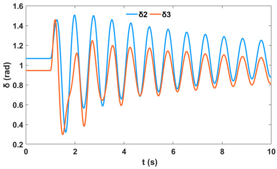
Figure 22.
Unstable relative power angle response w.r.t. of the interconnected power system for a three-phase contingency at bus 9 without PSS and NFC.
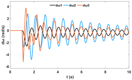
Figure 23.
Unstable rotor speed deviation response of the interconnected power system for a three-phase contingency at bus 9 without PSSs and NFC.
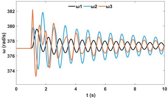
Figure 24.
Unstable rotor speed response of the interconnected power system for a three-phase contingency at bus 9 without PSSs and NFC.
3.2.2. Time-Domain Simulation of the Interconnected Test Power System with PSS Damping Controller for Operating Condition 1
For the PSS stabilizer design, a symmetrical 100 ms three-phase fault was observed at , and a nonlinear time-domain simulation was performed. The rate at which the PSS design index converges using the FFA search algorithm is shown in Figure 25, while the optimal parameters of the designed PSSs are shown in Table 8. From the convergence characteristics, the FFA method shows a good convergence rate at 41 iterations.
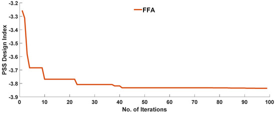
Figure 25.
Convergence characteristics of FFA in finding the optimal design of PSS.
Table 8.
Optimal PSS parameters using the FFA search algorithm.
Table 9 shows the eigenvalues results with their associated damping ratio and frequency for the power system case with PSS installed in the system, respectively. From Table 7, Mode 1 and Mode 2 produce a weak damping ratio for the system without a controller. After the optimal PSS design, these modes were impressively enhanced from and to and respectively, using the FFA design method. Similarly, the worst damping ratio EM was improved from to using the FFA design method. Similarly, Figure 26 illustrates the eigenvalues plot for the system with the FFA-PSS controller based on the numerical simulation results of Table 7 and Table 9.
Table 9.
WSCC interconnected power system eigenvalues and their related damping ratios of the EMs for FFA PSS design algorithms.
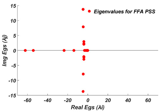
Figure 26.
Eigenvalues plot for the system with the FFA-PSS damping controller.
Moreover, a nonlinear time-domain simulation was performed and Figure 27 shows the stable generator power angles δ relative to in radian for the interconnected test power system for FFA-PSS, while Figure 28 shows the stable generator speed deviations response in radian per seconds for and , respectively. Similarly, Figure 29 shows the stable system rotor speed response in radian per seconds for and , respectively, for the FFA-PSS.
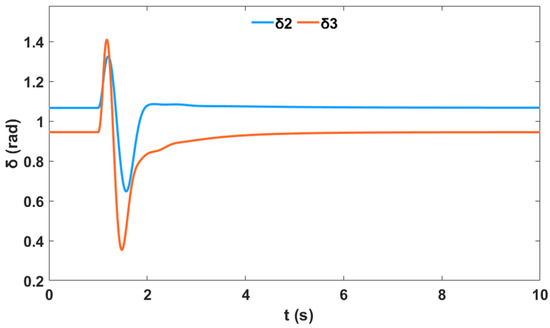
Figure 27.
Stable relative power angle response w.r.t. of the interconnected power system for a three-phase contingency at bus 9 with FFA-PSS for operating condition 1.
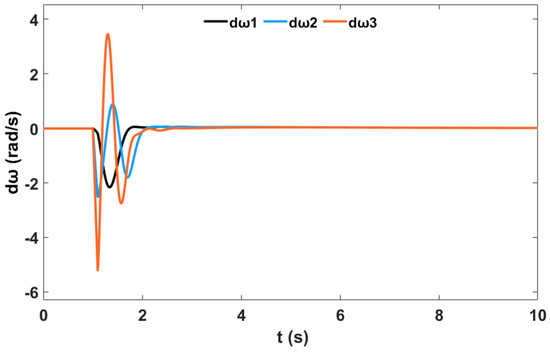
Figure 28.
Stable rotor speed deviation response of the interconnected power system for a three-phase contingency at bus 9 with FFA-PSS for operating condition 1.
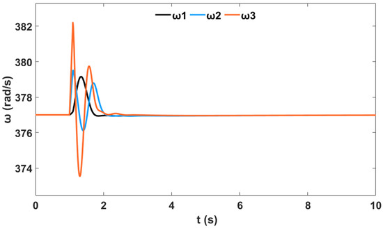
Figure 29.
Stable rotor speed response of the interconnected power system for a three-phase contingency at bus 9 with FFA-PSS for operating condition 1.
3.2.3. Time-Domain Simulation of the Interconnected Test Power System with NFC Damping Controller for Operating Condition 1
In this case, the test power system is equipped with an NFC stabilizer, and a symmetrical three-phase fault is subjected to the system. Table 10 shows the eigenvalues results with their associated damping ratio and frequency for the power system case with NFC installed in the system, respectively. From Table 7, Mode 1 and Mode 2 produce a weak damping ratio for the system without a controller. After the NFC design, these modes were impressively enhanced from and to and respectively, using the NFC stabilizer. Similarly, the worst damping ratio of EM was improved from to using the NFC. Similarly, Figure 30 illustrates the eigenvalues plot for the system with the NFC stabilizer controller based on the numerical simulation results of Table 7 and Table 10.
Table 10.
WSCC interconnected power system eigenvalues and their related damping ratios of the EMs for the NFC damping controller.
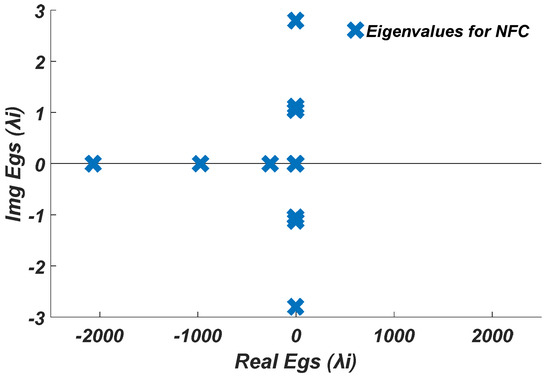
Figure 30.
Eigenvalues plot for the system with the NFC damping controller.
Moreover, a nonlinear time-domain simulation was performed with NFC installed in the system, and Figure 31 shows the stable generator relative power angles δ in radian for the system with NFC, while Figure 32 shows the stable generator speed deviation in radian per second for the system with NFC. Similarly, Figure 33 shows the stable system rotor speed response in radian per second for the system with NFC.
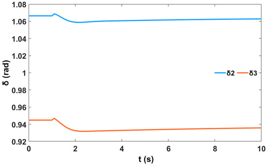
Figure 31.
Stable relative power angle response w.r.t. of the interconnected power system for a three-phase contingency at bus 9 with NFC for operating condition 1.
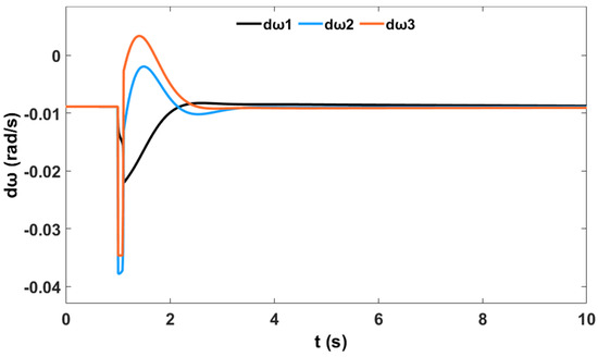
Figure 32.
Stable rotor speed deviation response of the interconnected power system for a three-phase contingency at bus 9 with NFC for operating condition 1.
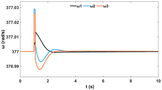
Figure 33.
Stable rotor speed response of the interconnected power system for a three-phase contingency at bus 9 with NFC for operating condition 1.
3.2.4. Comparison between the Proposed NFC and PSS Damping Controllers for Operating Condition 1
This section presents comparative simulation results between the proposed NFC and the PSS damping controllers for LFO’s robustness. The generator power angles δ in radian for and with respect to illustrate the system stability profile of the system without the controller, with PSS, and with the proposed NFC, as shown in Figure 34 and Figure 35, respectively.
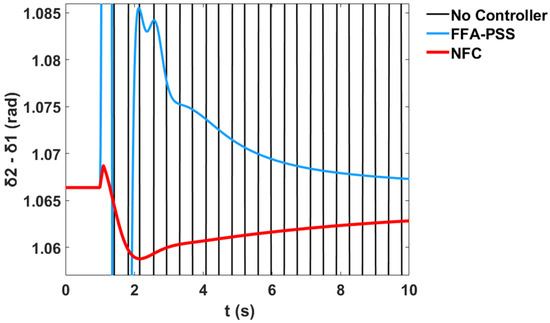
Figure 34.
Power angle response of G2 relative to G1 for a contingency at bus 9 in the interconnected power system for operating condition 1.
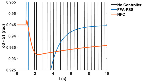
Figure 35.
Power angle response of G3 relative to G1 for a contingency at bus 9 in the interconnected power system for operating condition 1.
The variation in the generator speeds for and relative to corresponds to the system stability profile of the system without the controller, with PSS, and with the proposed NFC, as shown in Figure 36 and Figure 37 respectively.
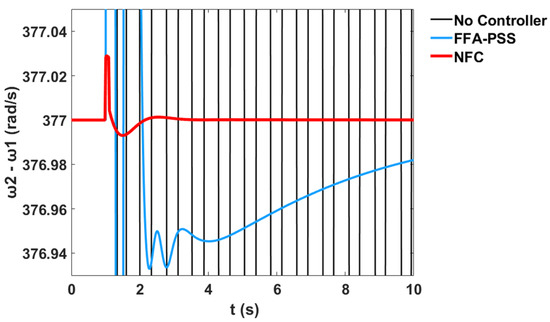
Figure 36.
Rotor speed response of G2 relative to G1 for a contingency at bus 9 in the interconnected power system for operating condition 1.
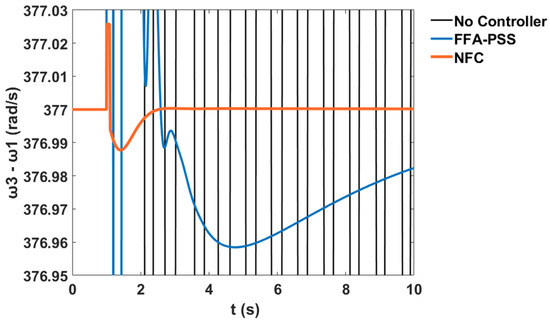
Figure 37.
Rotor speed response of G3 relative to G1 for a contingency at bus 9 in the interconnected power system for operating condition 1.
From the time-domain simulation results, it was seen that the stabilizer using the proposed NFC was effectively able to damp out the LFOs of the test system under severe system disturbances. Thus, the NFC damping controller can be applied as a general damping controller for the robust design stabilizer and other similar science and engineering controller applications.
3.2.5. Proposed FFA Based NFC Design Results Comparison with FFA-PSS for Operating Condition 2
To verify the performance of the proposed NFC controller, this section considers a 120% increase in active power on generator 2 and generator 3. Relative power angles δ in radian for and with respect to illustrate the system stability profile of the system using FFA-PSS and the proposed NFC design methods, as shown in Figure 38 and Figure 39 respectively.
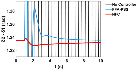
Figure 38.
Power angle response of G2 relative to G1 for a contingency at bus 9 in the interconnected power system for operating condition 2.
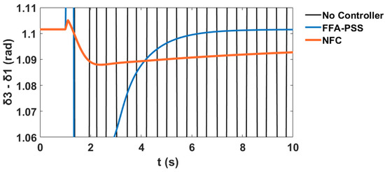
Figure 39.
Power angle response of G3 relative to G1 for a contingency at bus 9 in the interconnected power system for operating condition 2.
The variation in the generator speeds for and relative to that corresponds to the system stability profile of the system using FFA-PSS, and the proposed NFC design methods are shown in Figure 40 and Figure 41 respectively.
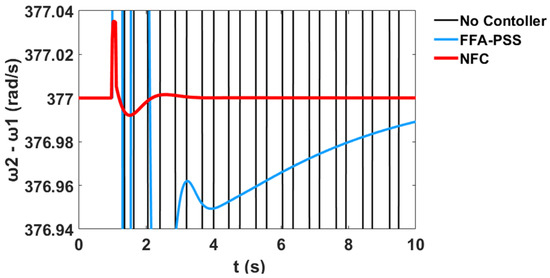
Figure 40.
Rotor speed response of G2 relative to G1 for a contingency at bus 9 in the interconnected power system for operating condition 2.
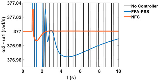
Figure 41.
Rotor speed response of G3 relative to G1 for a contingency at bus 9 in the interconnected power system for operating condition 2.
3.2.6. Proposed FFA Based NFC Design Results Comparison with FFA-PSS for Operating Condition 3
The section on condition 3 considers an 80% decrease in active power on generator 2 and generator 3. Relative power angles δ in radian for and with respect to illustrate the system stability profile of the system using FFA-PSS, and the proposed NFC design methods as shown in Figure 42 and Figure 43 respectively.
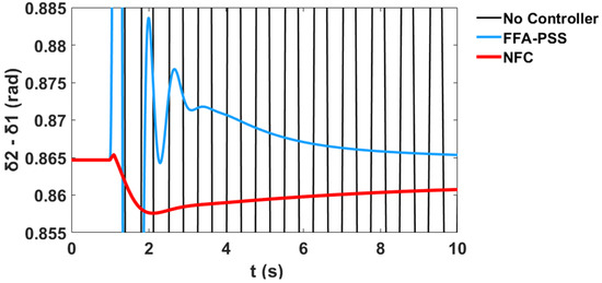
Figure 42.
Power angle response of G2 relative to G1 for a contingency at bus 9 in the interconnected power system for operating condition 3.
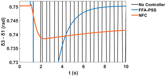
Figure 43.
Power angle response of G3 relative to G1 for a contingency at bus 9 in the interconnected power system for operating condition 3.
The variation in the generator speeds for and relative to corresponds to the system stability profile of the system using FFA-PSS, and the proposed NFC design methods are shown in Figure 44 and Figure 45 respectively.
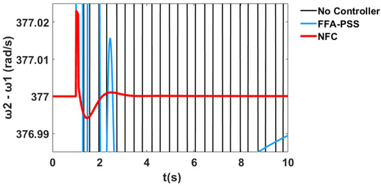
Figure 44.
Rotor speed response of G2 relative to G1 for a contingency at bus 9 in the interconnected power system for operating condition 3.
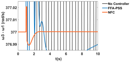
Figure 45.
Rotor speed response of G3 relative to G1 for a contingency at bus 9 in the interconnected power system for operating condition 3.
3.2.7. Transient Response Scenario for Controller Performance Analysis under Operating Condition 1
This section explains the transient response simulation which describes the performance analysis of the interconnected power system when the system has no controller (NC), with a PSS controller, and with the proposed NFC damping controller for the three machines, respectively. Table 11 considers how the Machine 1 plant responds to the transient situation with respect to settling time (ST), rise time (RT), peak time (PT), and peak magnitude (PM) for NC, PSS, and NFC damping controller cases, respectively. It is seen that the rotor speed for machine 1’s transient response, , in terms of settling time and rise time, is remarkably improved by an amount of 66.57% and 64.70%, respectively, by the proposed NFC stabilizer, as compared with the NC in the system.
Table 11.
Machine 1’s transient performance.
Furthermore, Table 12 shows, for Machine 2’s system, that the ST response for was remarkably improved by an amount of 69.66% when the system had NC as compared to the proposed NFC stabilizer. Similarly, Table 13 explains, for Machine 3’s system, how the reacts to ST when the system has NC and when the NFC stabilizer is used. The FFA controller was able to improve the system’s stability in terms of ST with an amount of 75.70% and thus damp out the LFOs under credible contingency.
Table 12.
Machine 2’s transient performance.
Table 13.
Machine 3’s transient performance.
The NFC damping controller in all the three machines’ transient simulation analyses was found to be able to improve the system’s stability in terms of ST, RT, PT, and PM by an acceptable amount, compared with the PSS, and thus to damp out the LFOs under credible contingency. Nonetheless, the minimum control effort of the NFC damping controller exhibited its effectiveness to control LFOs and thereby enhance the overall dynamic stability of the interconnected system compared to the application of the PSS damping controller.
3.3. IEEE 10-Machine Test Power System Results and Discussion under Operating Condition 1
This section of the work considered the well-known IEEE 10-machine, 39-bus New England power system as the test system. The single line configurations of the power system are shown in Figure 46, and the complete system data can be found in [31]. The dynamic stability of the test system can be obtained considering generator G2, which is an equivalent power source representing parts of the USA-Canadian interconnection system as the reference generator, which is not equipped with the PSSs. The interconnected synchronous generators are represented by fourth-order models of the DAEs explained by the test system modeling equations described earlier.
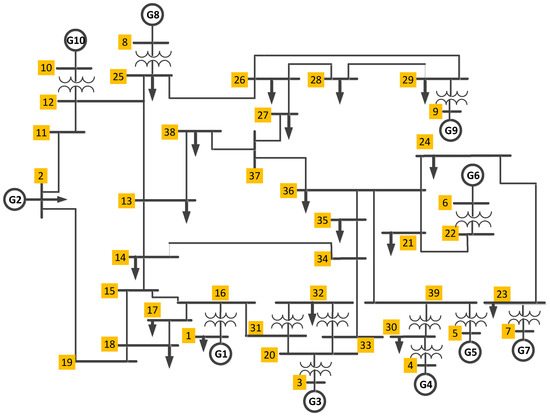
Figure 46.
IEEE 10-machine, 39-bus power system single line structure.
This section discusses the eigenvalue, time-domain, and transient response simulation results of the three test power systems under multiple operating conditions. The performance of the proposed NFC stabilizer was assessed for three different operating conditions, taking into account criteria such as settling time (ST), rise time (RT), peak time (PT), and peak magnitude (PM). The operating conditions are given below.
- ➢
- Condition-1: contingency at bus 39 with no change in the system loading.
- ➢
- Condition-2: contingency at bus 39 with a 120% increase in active power on generator 5 and generator 8.
- ➢
- Condition-3: contingency at bus 39 with an 80% decrease in active power on generator 5 and generator 8.
3.3.1. Time-Domain Simulation of the 10-Machine Test Power System without PSS and NFC Damping Controllers under Operating Condition 1
In this section, the system undergoes a disturbance without a damping controller (PSSs and NFC) for LFOs mitigation, and hence system stability enhancement. An eigenvalues simulation analysis and nonlinear time-domain simulations should be carried out for comprehensive evaluation. The test system was subjected to a three-phase fault without a PSS damping controller. A symmetrical 100 ms three-phase fault was observed at , and a nonlinear time-domain simulation was performed. After the fault was cleared, at 0.2 s, the system’s stable condition was restored. Table 14 shows the eigenvalues results with their associated damping ratio and frequency for the power system case without the PSS and NFC installed. From Table 14, Mode 1 and Mode 2 produce a weak damping ratio for the no PSS case condition with and eigenvalues. Similarly, the worst damping ratio EM was found to be and respectively.
Table 14.
New England interconnected test power system eigenvalues and damping ratio of the EMs without PSS and NFC.
In this section, the system undergoes a disturbance without PSSs and NFC damping controller for LFOs mitigation, and hence system stability enhancement. A nonlinear time-domain simulation was performed, and Figure 47 shows the unstable generator power angles δ relative to in radian for the interconnected test power system for the operating condition 1, while Figure 48 shows the unstable generator speed deviation in radian per second for the system without PSS and NFC for the operating condition 1. Similarly, Figure 49 shows the unstable system rotor speed response in radian per second for the system without PSS and NFC for the interconnected test power system.
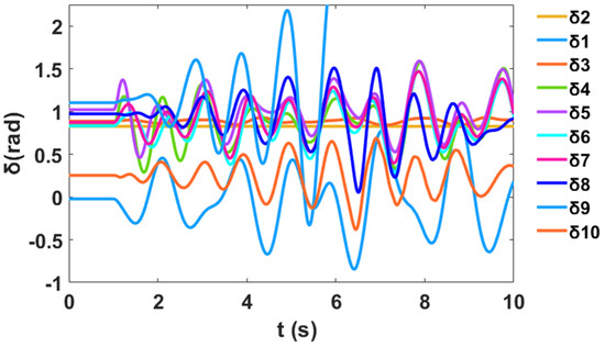
Figure 47.
Unstable relative power angle response w.r.t. of the interconnected power system for a three-phase contingency at bus 39 without PSS and NFC.
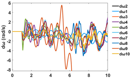
Figure 48.
Unstable rotor speed deviation response of the interconnected power system for a three-phase contingency at bus 39 without PSSs and NFC.
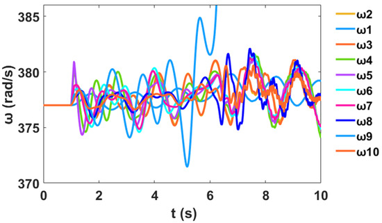
Figure 49.
Unstable rotor speed response of the interconnected power system for a three-phase contingency at bus 9 without PSSs and NFC.
3.3.2. Time-Domain Simulation of the Interconnected Test Power System with PSS Damping Controller for Operating Condition 1
For the PSS stabilizer design, a symmetrical 100 ms three-phase fault was observed at , and a nonlinear time-domain simulation was performed. The rate at which the PSS design index converges using the FFA search algorithm is shown in Figure 50, while the optimal parameters of the designed PSSs are shown in Table 15. From the convergence characteristics, the FFA method shows a good convergence rate at 92 iterations.
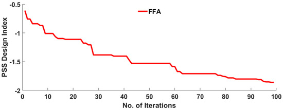
Figure 50.
Convergence characteristics of FFA in finding the optimal design of PSS.
Table 15.
Optimal PSS parameters using the FFA search algorithm.
Table 16 shows the eigenvalues results with their associated damping ratio and frequency for the power system case with PSS installed in the system, respectively. From Table 14, Mode 1 and Mode 2 produce a weak damping ratio for the system without a controller. After the optimal PSS design, these modes were impressively enhanced from and to and respectively, using the FFA design method. Similarly, the worst damping ratio EM was improved from to using the FFA design method. Similarly, Figure 51 illustrates the eigenvalues plot for the system with the FFA-PSS controller based on the numerical simulation results of Table 14 and Table 16.
Table 16.
10-machine interconnected power system eigenvalues and their related damping ratios of the EMs for FFA PSS design algorithms.
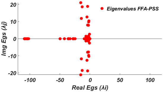
Figure 51.
Eigenvalues plot for the system with the FFA-PSS damping controller.
Moreover, a nonlinear time-domain simulation was performed, and Figure 52 shows the stable generator power angles δ relative to in radian for the interconnected test power system for FFA-PSS, while Figure 53 shows the stable generator speed deviations response in radian per seconds for to , respectively. Similarly, Figure 54 shows the stable system rotor speed response in radian per seconds for to , respectively, for the FFA-PSS.
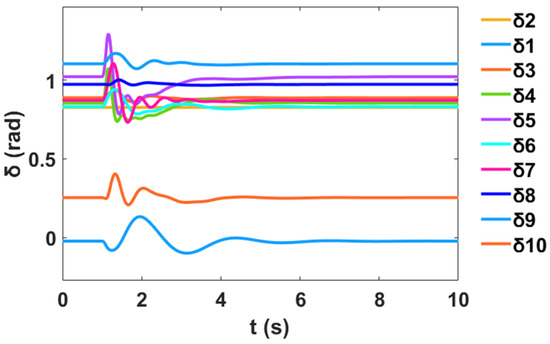
Figure 52.
Stable relative power angle response w.r.t. of the interconnected power system for a three-phase contingency at bus 39 with FFA-PSS for operating condition 1.
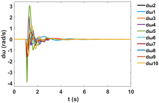
Figure 53.
Stable rotor speed deviation response of the interconnected power system for a three-phase contingency at bus 39 with FFA-PSS for operating condition 1.
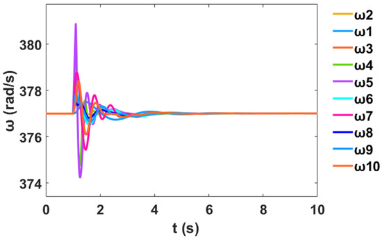
Figure 54.
Stable rotor speed response of the interconnected power system for a three-phase contingency at bus 39 with FFA-PSS for operating condition 1.
3.3.3. Time-Domain Simulation of the Interconnected Test Power System with NFC Damping Controller for Operating Condition 1
In this case, the test power system was equipped with an NFC stabilizer, and a symmetrical three-phase fault was subjected to the system. Table 17 shows the eigenvalues results with their associated damping ratio and frequency for the power system case with NFC installed in the system, respectively. From Table 14, Mode 1 and Mode 2 produce a weak damping ratio for the system without a controller. After the NFC design, these modes were impressively enhanced from and to and respectively, using the NFC stabilizer. Similarly, the worst damping ratio of EM was improved from to using the NFC.
Table 17.
10-machine interconnected power system eigenvalues and their related damping ratios of the EMs for the NFC damping controller.
Moreover, a nonlinear time-domain simulation was performed with NFC installed in the system, and Figure 55 shows the stable generator relative power angles δ in radian for the system with NFC, while Figure 56 shows the stable generator speed deviation in radian per second for the system with NFC. Similarly, Figure 57 shows the stable system rotor speed response in radian per second for the system with NFC.
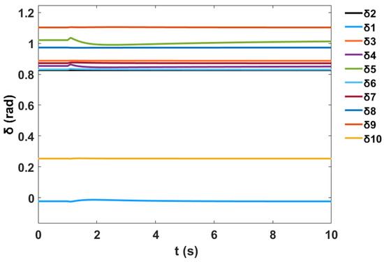
Figure 55.
Stable relative power angle response w.r.t. of the interconnected power system for a three-phase contingency at bus 39 with NFC for operating condition 1.
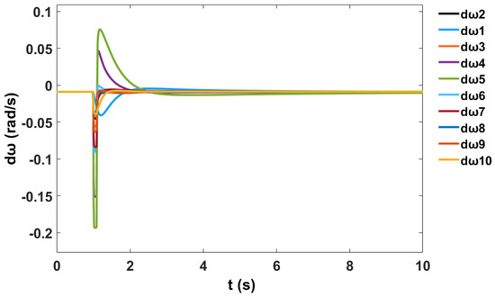
Figure 56.
Stable rotor speed deviation response of the interconnected power system for a three-phase contingency at bus 39 with NFC for operating condition 1.
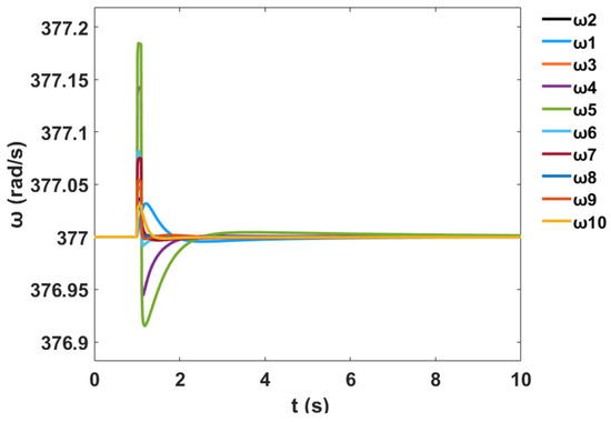
Figure 57.
Stable rotor speed response of the interconnected power system for a three-phase contingency at bus 39 with NFC for operating condition 1.
3.3.4. Comparison between the Proposed NFC and PSS Damping Controllers for Operating Condition 1
This section presents comparative simulation results between the proposed NFC and the PSS damping controllers for LFO’s robustness. The generator power angles δ in radian for and with respect to illustrate the system stability profile of the system without the controller, with PSS, and with the proposed NFC, as shown in Figure 58 and Figure 59 respectively.
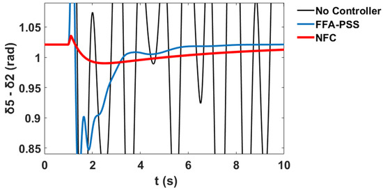
Figure 58.
Power angle response of G5 relative to G2 for a contingency at bus 39 in the interconnected power system for operating condition 1.
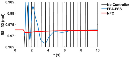
Figure 59.
Power angle response of G8 relative to G2 for a contingency at bus 39 in the interconnected power system for operating condition 1.
The variation in the generator speeds for and relative to corresponds to the system stability profile of the system without the controller, with PSS, and with the proposed NFC, as shown in Figure 60 and Figure 61 respectively.
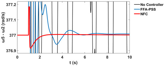
Figure 60.
Rotor speed response of G5 relative to G2 for a contingency at bus 39 in the interconnected power system for operating condition 1.
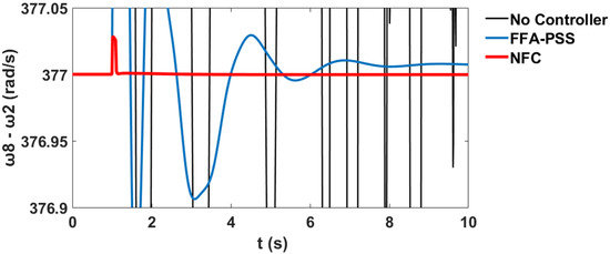
Figure 61.
Rotor speed response of G8 relative to G2 for a contingency at bus 39 in the interconnected power system for operating condition 1.
From the time-domain simulation results, it was seen that the stabilizer using the proposed NFC was effectively able to damp out the LFOs of the test system under severe system disturbances. Thus, the NFC damping controller can be applied as a general damping controller for the robust design stabilizer and other similar science and engineering controller applications.
3.3.5. Proposed NFC Design Results Comparison with FFA-PSS for Operating Condition 2
To verify the performance of the proposed NFC controller, this section considers a 120% increase in active power on generator 5 and generator 8. Relative power angles δ in radian for and with respect to illustrate the system stability profile of the system using FFA-PSS and the proposed NFC design methods, as shown in Figure 62 and Figure 63 respectively.
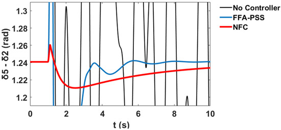
Figure 62.
Power angle response of G5 relative to G2 for a contingency at bus 39 in the interconnected power system for operating condition 2.
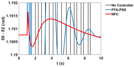
Figure 63.
Power angle response of G8 relative to G2 for a contingency at bus 39 in the interconnected power system for operating condition 2.
The variation in the generator speeds for and relative to corresponds to the system stability profile of the system using FFA-PSS, and the proposed NFC design methods are shown in Figure 64 and Figure 65 respectively.
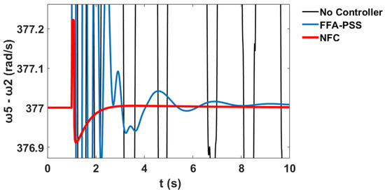
Figure 64.
Rotor speed response of G5 relative to G2 for a contingency at bus 39 in the interconnected power system for operating condition 2.
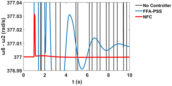
Figure 65.
Rotor speed response of G8 relative to G2 for a contingency at bus 39 in the interconnected power system for operating condition 2.
3.3.6. Proposed NFC Design Results Comparison with FFA-PSS for Operating Condition 3
The section on condition 3 considers an 80% decrease in active power on generator 5 and generator 8. Relative power angles δ in radian for and with respect to illustrate the system stability profile of the system using FFA-PSS and the proposed NFC design methods, as shown in Figure 66 and Figure 67 respectively.
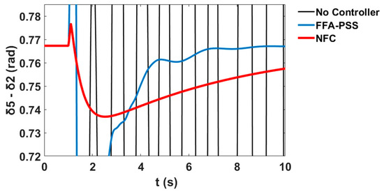
Figure 66.
Power angle response of G5 relative to G2 for a contingency at bus 39 in the interconnected power system for operating condition 3.
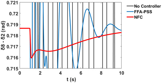
Figure 67.
Power angle response of G8 relative to G2 for a contingency at bus 39 in the interconnected power system for operating condition 3.
The variation in the generator speeds for and relative to corresponds to the system stability profile of the system using FFA-PSS, and the proposed NFC design methods are shown in Figure 68 and Figure 69 respectively.
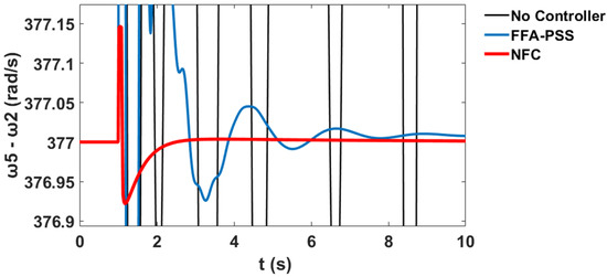
Figure 68.
Rotor speed response of G5 relative to G2 for a contingency at bus 39 in the interconnected power system for operating condition 3.
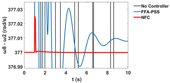
Figure 69.
Rotor speed response of G8 relative to G2 for a contingency at bus 39 in the interconnected power system for operating condition 3.
3.3.7. Transient Response Scenario for Controller Performance Analysis under Operating Condition 1
This section explains the transient response simulation which describes the performance analysis of the interconnected power system when the system has no controller (NC), with a PSS controller, and with the proposed NFC damping controller for the two machines, respectively. Table 18 and Table 19 illustrate how Generator 5 and Generator 8 respond to the transient situation with respect to settling time (ST), rise time (RT), peak time (PT), and peak magnitude (PM) for NC, PSS, and NFC damping controller cases, respectively. It was seen that the rotor speed for machine 5’s transient response in terms of settling time and rise time was remarkably improved, by 76.80% and 96.16%, respectively, by the proposed NFC stabilizer, as compared with the NC in the system.
Table 18.
Machine 5’s transient performance.
Table 19.
Machine 8’s transient performance.
Furthermore, Table 19 shows that the rotor speed for machine 8’s transient response in terms of settling time was remarkably improved by 77.33% by the proposed NFC stabilizer, as compared with the NC in the system.
The NFC damping controller in all the three machines’ transient simulation analyses was found to be able to improve the system stability in terms of ST, RT, PT, and PM by an acceptable amount, as compared with the PSS, and thus to damp out the LFOs under credible contingency. Nonetheless, the minimum control effort of the NFC damping controller exhibited its effectiveness to control LFOs and thereby enhance the overall dynamic stability of the interconnected system compared to the application of the PSS damping controller.
4. Conclusions
In this paper, the performance of the neuro-fuzzy controller (NFC) as a stabilizer to replace conventional single machine infinite bus (SMIB) and interconnected multi-machine large power system stabilizers (PSSs) design was assessed. The drawback of the conventional PSSs on SMIB and interconnected multi-machine test power systems were exposed and disclosed by the proposed NFC stabilizer. The proposed NFC stabilizer is a nonlinear robust controller which does not require a mathematical model of the test power system to be controlled, unlike the conventional PSS damping controller. The Proposed NFC is designed to improve the stability of SMIB, an interconnected IEEE 3-machine, 9-bus power system, and an interconnected two-area 10-machine system of 39-bus New England IEEE test power system under multiple operating conditions. Through the application of the proposed NFC stabilizer on the three-test systems, the damping ratio of the electromechanical modes (EMs) has increased from to for the SMIB test-system, to for the 3-machine test system, and to for the 10-machine test system, respectively. This damping ratio is an acceptable value for EMs because it has increased to a value greater than 0.1. Nonlinear simulations were carried out for the designed PSSs with MATLAB/SIMULINK software. The variations in different quantities of the three test power systems, due to no change in the system loading condition, with a 120% increase in active power on generator 5 and generator 8 and with an 80% decrease in active power on generator 5 and generator 8, respectively, revealed the effectiveness of the proposed NFC stabilizer. It was observed in the Figures from the nonlinear time-domain simulations that oscillations have become significantly damped for all three test systems under these system operating variations using the proposed method. Moreover, the phasor simulation results show that the transient responses of the system rise time, settling time, peak time, and peak magnitude were all impressively improved by an acceptable amount for the three test systems with the proposed NFC stabilizer. Thus, the application and performance of the proposed NFC stabilizer in replacing the conventional PSSs for SMIB and large multi-machine power systems have appeared robust and superior and can be considered as a very remarkable technique for the optimal design of the damping controller in large interconnected power systems.
Author Contributions
A.S. proposed the main idea and performed the simulation of the work; A.S. and N.I.A.W. wrote this paper; H.B. and H.A. provided sources and assisted in writing the paper; H.B. and H.A. simulated the comparative methods; the proofreading and final drafting were done by M.L.O. and M.Z.A.M.J. All authors have read and agreed to the published version of the manuscript.
Funding
This research work was supported in part by the GPB-UPM, under Grant no. 9630000.
Acknowledgments
The authors are thankful to the University Putra Malaysia (UPM) through the Advanced Lightning, Power, and Energy Research (ALPER). We also thank the Nigerian Defence Academy, NDA Kaduna, for their support.
Conflicts of Interest
The authors declare no conflict of interest.
References
- Wang, Y.; Yuan, Y. Inertia provision and small signal stability analysis of a wind-power generation system using phase-locked synchronized equation. Sustainability 2019, 11, 1400. [Google Scholar] [CrossRef]
- Veerasamy, V.; Izzri, N.; Wahab, A.; Ramachandran, R. Automatic Load Frequency Control of a Multi-Area Dynamic Interconnected Power System Using a Hybrid PSO-GSA-Tuned PID Controller. Sustainability 2019, 11, 6908. [Google Scholar] [CrossRef]
- Hu, W.; Liang, J.; Jin, Y.; Wu, F. Model of power system stabilizer adapting to multi-operating conditions of local power grid and parameter tuning. Sustainability 2018, 10, 2089. [Google Scholar] [CrossRef]
- Maity, S.; Ramya, R. A comprehensive review of damping of low frequency oscillations in power systems. Int. J. Innov. Technol. Explor. Eng. 2019, 8, 133–138. [Google Scholar]
- Lee, H.J.; Jhang, S.S.; Yu, W.K.; Oh, J.H. Artificial neural network control of battery energy storage system to damp-out inter-area oscillations in power systems. Energies 2019, 12, 3372. [Google Scholar] [CrossRef]
- Gao, B.; Xia, C.; Chen, N.; Cheema, K.M.; Yang, L.; Li, C. Virtual synchronous generator based auxiliary damping control design for the power system with renewable generation. Energies 2017, 10, 1146. [Google Scholar] [CrossRef]
- Shim, K.S.; Ahn, S.J.; Choi, J.H. Synchronization of low-frequency oscillation in power systems. Energies 2017, 10, 558. [Google Scholar] [CrossRef]
- Zuo, J.; Li, Y.; Shi, D.; Duan, X. Simultaneous robust coordinated damping control of power system stabilizers (PSSS), static var compensator (SVC) and doubly-fed induction generator power oscillation dampers (DFIG PODs) in multimachine power systems. Energies 2017, 10, 565. [Google Scholar]
- Liu, Z.; Yao, W.; Wen, J. Enhancement of power system stability using a novel power system stabilizer with large critical gain. Energies 2017, 10, 449. [Google Scholar] [CrossRef]
- Junior, F.A.A.; Junior, C.T.; de Medeiros, R.L.P.; Junior, W.B.; Neves, C.C.; Lenzi, M.K.; Veroneze, G. A fractional order power system stabilizer applied on a small-scale generation system. Energies 2018, 11, 2052. [Google Scholar] [CrossRef]
- Faraji, A.; Naghshbandy, A.H. A combined approach for power system stabilizer design using continuous wavelet transform and SQP algorithm. Int. Trans. Electr. Energy Syst. 2019, 29, e2768. [Google Scholar] [CrossRef]
- Feng, S.; Jiang, P.; Wu, X. Suppression of power system forced oscillations based on PSS with proportional-resonant controller. Int. Trans. Electr. Energy Syst. 2017, 27, e2328. [Google Scholar] [CrossRef]
- Ekinci, S.; Demiroren, A.; Hekimoglu, B. Parameter optimization of power system stabilizers via kidney-inspired algorithm. Trans. Inst. Meas. Control 2019, 41, 1405–1417. [Google Scholar] [CrossRef]
- Gupta, A.K.; Verma, K.; Niazi, K.R. Robust coordinated control for damping low frequency oscillations in high wind penetration power system. Int. Trans. Electr. Energy Syst. 2019, 29, e12006. [Google Scholar] [CrossRef]
- Wahab, N.I.A.; Mohamed, A.; Hussain, A. Fast transient stability assessment of large power system using probabilistic neural network with feature reduction techniques. Expert Syst. Appl. 2011, 38, 11112–11119. [Google Scholar] [CrossRef]
- Hekimoğlu, B. Robust fractional order PID stabilizer design for multi-machine power system using grasshopper optimization algorithm. J. Fac. Eng. Archit. Gazi Univ. 2020, 35, 165–180. [Google Scholar]
- Wahab, N.I.A.; Mohamed, A.; Hussain, A. Feature selection and extraction methods for power systems transient stability assessment employing computational intelligence techniques. Neural Process. Lett. 2012, 35, 81–102. [Google Scholar] [CrossRef]
- Miotto, E.L.; de Araujo, P.B.; Fortes, E.D.V.; Gamino, B.R.; Fabiano, L.; Martins, B. Coordinated Tuning of the Parameters of PSS and POD Controllers Using Bioinspired Algorithms. IEEE Trans. Ind. Appl. 2018, 54, 3845–3857. [Google Scholar] [CrossRef]
- Verdejo, H.; Torres, R.; Pino, V.; Kliemann, W.; Becker, C.; Delpiano, J. Tuning of Controllers in Power Systems Using a Heuristic-Stochastic Approach. Energies 2019, 12, 2325. [Google Scholar] [CrossRef]
- Mirfendereski, S.; Wahab, N.I.A.; Jasni, J. Mitigation of power system small signal oscillation using posicast controller and evolutionary programming. J. Eng. Sci. Technol. 2014, 10, 50–67. [Google Scholar]
- Jokarzadeh, M.; Abedini, M.; Seifi, A. Improving power system damping using a combination of optimal control theory and differential evolution algorithm. ISA Trans. 2019, 90, 169–177. [Google Scholar] [CrossRef]
- Guesmi, T.; Farah, A.; Abdallah, H.H.; Ouali, A. Robust design of multimachine power system stabilizers based on improved non-dominated sorting genetic algorithms. Electr. Eng. 2018, 100, 1351–1363. [Google Scholar] [CrossRef]
- Wang, D.; Ma, N.; Wei, M.; Liu, Y. Parameters tuning of power system stabilizer PSS4B using hybrid particle swarm optimization algorithm. Int. Trans. Electr. Energy Syst. 2018, 28, e2598. [Google Scholar] [CrossRef]
- Dasu, B.; Sivakumar, M.; Srinivasarao, R. Interconnected multi-machine power system stabilizer design using whale optimization algorithm. Prot. Control Mod. Power Syst. 2019, 4, 2. [Google Scholar] [CrossRef]
- Ekinci, S.; Hekimoǧlu, B. Parameter optimization of power system stabilizer via Salp Swarm algorithm. In Proceedings of the 2018 5th International Conference on Electrical and Electronic Engineering (ICEEE), Istanbul, Turkey, 3–5 May 2018; pp. 143–147. [Google Scholar]
- Ibrahim, N.M.A.; Elnaghi, B.E.; Ibrahim, H.A.; Talaat, H.E.A. Performance Assessment of Bacterial Foraging based Power System Stabilizer in Multi-Machine Power System. Int. J. Intell. Syst. Appl. 2019, 11, 43–53. [Google Scholar] [CrossRef]
- Ekinci, S. Optimal design of power system stabilizer using sine cosine algorithm. J. Fac. Eng. Archit. Gazi Univ. 2019, 34, 1329–1350. [Google Scholar]
- Chaib, L.; Choucha, A.; Arif, S. Optimal design and tuning of novel fractional order PID power system stabilizer using a new metaheuristic Bat algorithm. Ain Shams Eng. J. 2017, 8, 113–125. [Google Scholar] [CrossRef]
- Chitara, D.; Member, S.; Niazi, K.R.; Member, S. Cuckoo Search Optimization Algorithm for Designing of a Multimachine Power System Stabilizer. IEEE Trans. Ind. Appl. 2018, 54, 3056–3065. [Google Scholar] [CrossRef]
- Ekinci, S.; Demiroren, A. Modeling, simulation, and optimal design of power system stabilizers using ABC. Turk. J. Electr. Eng. Comput. Sci. 2016, 24, 1532–1546. [Google Scholar] [CrossRef]
- Beiranvand, H.; Rokrok, E. General Relativity Search Algorithm: A Global Optimization Approach. Int. J. Comput. Intell. Appl. 2015, 14, 1550017. [Google Scholar] [CrossRef]
- Abdulkhader, H.K.; Jacob, J.; Mathew, A.T. Multi-band power system stabiliser design using a hybrid dynamic GA-PSO algorithm. IET Gener. Transm. Distrib. 2018, 12, 3248–3260. [Google Scholar] [CrossRef]
- Ke, D.; Shen, F.; Chung, C.Y.; Zhang, C.; Member, S. Application of Information Gap Decision Theory to the Design of Robust Wide-Area Power System Stabilizers Considering Uncertainties of Wind Power. IEEE Trans. Sustain. Energy 2018, 9, 805–817. [Google Scholar] [CrossRef]
- Çötelİ, R.; Açikgöz, H.; Dandil, B.; Tuncer, S. Real-time implementation of three-level inverter-based D-STATCOM using neuro-fuzzy controller. Turk. J. Electr. Eng. Comput. Sci. 2018, 26, 2088–2103. [Google Scholar] [CrossRef]
- Li, X.; Niu, Y.; Fu, J.; Zhang, X.; Lin, Z.; Niu, Y.-G. A neural power system stabilizer of DFIGs for power system stability support. Int. Trans. Electr. Energy Syst. 2018, 28, e2547. [Google Scholar] [CrossRef]
- Muljono, A.B.; Ginarsa, I.M.; Nrartha, I.M.A.; Dharma, A. Coordination of Adaptive Neuro Fuzzy Inference System (ANFIS ) and Type-2 Fuzzy Logic System-Power System Stabilizer (T2FLS-PSS ) to Improve a Large-scale Power System Stability. Int. J. Electr. Comput. Eng. 2018, 8, 76–86. [Google Scholar] [CrossRef]
- Tavakoli, A.R.; Seifi, A.R.; Arefi, M.M. Fuzzy-PSS and fuzzy neural network non-linear PI controller-based SSSC for damping inter-area oscillations. Trans. Inst. Meas. Control 2018, 40, 733–745. [Google Scholar] [CrossRef]
- Sambariya, D.K.; Prasad, R. A Novel Fuzzy Rule Matrix Design for Fuzzy Logic-based Power System Stabilizer. Electr. Power Compon. Syst. 2017, 45, 34–48. [Google Scholar] [CrossRef]
- Mondal, D.; Chakrabarti, A.; Sengupta, A. Power System Small Signal Stability Analysis and Control First Edition; Academic Press: New York, NY, USA; Elsevier Inc.: New York, NY, USA, 2014; pp. 1–336. [Google Scholar]
- H, C.J.; Ai, M.A.P.; Sauer, P.W. Power System Dynamics and Stability With Synchrophasor Measurement and Power System Toolbox; Wiley: Hoboken, NJ, USA, 2018. [Google Scholar]
- Wang, H.; Du, W. Analysis and Damping Control of Power System Low-Frequency Oscillations; Power Electronics and Power Systems; Springer: Berlin/Heidelberg, Germany, 2016; pp. 1–403. [Google Scholar]
- Beiranvand, H.; Rokrok, E. MatSim: A Matpower and Simulink based tool for Power System Dynamics Course Education. Available online: http://psc-ir.com/cd/2016/papers/1247.pdf (accessed on 29 October 2020).
- Kececioglu, O.F.; Acikgoz, H.; Yildiz, C.; Gani, A. Power Quality Improvement Using Hybrid Passive Filter Configuration for Wind Energy Systems. J. Electr. Eng. Technol. 2017, 12, 207–216. [Google Scholar] [CrossRef]
- Acikgoz, H.; Kececioglu, O.F.; Gani, A.; Yildiz, C.; Sekkeli, M. Improved control configuration of PWM rectifiers based on neuro—Fuzzy controller. Springerplus 2016, 5, 1142. [Google Scholar] [CrossRef]
- Shayanfar, H.; Gharehchopogh, F.S. Farmland fertility: A new metaheuristic algorithm for solving continuous optimization problems. Appl. Soft Comput. J. 2018, 71, 728–746. [Google Scholar] [CrossRef]
- Sabo, A.; Izzri, N.; Wahab, A.; Othman, M.L.; Zurwatul, M.; Mohd, A. Farmland Fertility Optimization for Designing of Interconnected Multi-machine Power System Stabilizer. Appl. Model. Simul. 2020, 4, 183–201. [Google Scholar]


Publisher’s Note: MDPI stays neutral with regard to jurisdictional claims in published maps and institutional affiliations. |
© 2020 by the authors. Licensee MDPI, Basel, Switzerland. This article is an open access article distributed under the terms and conditions of the Creative Commons Attribution (CC BY) license (http://creativecommons.org/licenses/by/4.0/).