


Abstract
This article introduces a new Multi-Source DC-DC converter-based smart energy management system on a common DC bus architecture, utilizing solar PV and wind sources for electric vehicle applications. The common DC bus enables coordinated power flow control among multiple sources while maintaining modularity and flexibility. To promote efficient battery charging and discharging, as well as enhanced protection from faults, an artificial neural network (ANN) approach has been incorporated. The main function of the ANN controller is to detect faults in the EV battery for timely intervention. Compared to existing topologies, its coordinated integration and control can operate effectively under dynamic conditions and improve stability. Additionally, the article presents the operating principle, modes of operation, design analysis, and control strategy. The simulation results of the proposed system are evaluated through MATLAB Simulink software 2024b. Furthermore, a 200 W laboratory prototype was developed to validate the system’s dynamic performance under various operating conditions.
1. Introduction
Utilizing renewable sources such as solar photovoltaic systems, wind energy, fuel cells, and supercapacitors, has improved the efficiency and significantly contributed to the transportation sector by reducing harmful emissions and fossil fuel consumption. Power electronics converters act as the main interface for power transfer in vehicles such as BEV, PHEV, and fuel-type vehicles. The article in [1] briefly discusses electric vehicle power converters, circuit topologies, and DC-AC power converters for both present and future electric vehicle technologies. To satisfy the operational requirements such as wide voltage range, higher efficiency, and bidirectional capability, multi-source converters are mostly employed, which improve the reliability and efficiency of the system [2]. In [3], multiple-output converters are preferred due to their reduction in power losses, component reduction, and higher power density. Integration of a bidirectional AC/DC and DC/DC converters in electric vehicle applications are investigated in many studies, which achieve higher power density and efficiency. Certain parameters, such as switching frequency, number of components, and output voltage gain, are compared with existing topologies and have been reviewed in the literature [4,5].
Multi-source converters that can manage grid power quality and perform multiple power conversion functions were detailed in [6]. Its additional features include vehicle-to-vehicle charging, low-power auxiliary supplies, and motoring and single-phase charging methods [7]. In [8], a multifunctional bidirectional converter is introduced to achieve high-efficiency power conversion into various forms with an efficiency of 92%. In most cases, a three-port converter can enhance both power density and reliability by integrating the onboard charger with low-voltage converters. The main advantage of multi-source integrated converters is to facilitate onboard charging and low-voltage conversion for auxiliary loads in electric vehicles [9,10]. However, bidirectional converters usually form a hybrid system that supports battery condition monitoring, fault detection, thermal management, and efficiency optimization [11,12], but it cannot employ multiple sources for the charging system. In another study, a structure utilizing dual sources is analyzed for electric vehicle applications without the need for any additional auxiliary circuit [13]. Bidirectional topologies, PWM isolated converters, dual-active-bridge converters, and resonant converters play a prominent role in the electric vehicle sector and were discussed briefly in [14]. These works briefly review recent advances of deep learning techniques, predictive control, hybrid optimization methods, fuzzy logic, and neural network approaches in power electronics, which substantially improve efficiency and performance of the converters [15,16]. Among all control techniques, artificial neural networks (ANNs) are generally considered as a smart power management strategy (PMS) controller to coordinate renewable energy use and monitor fuel efficiency in hybrid-type electric vehicles [17]. In [18], an interleaved step-up converter is coupled via a central capacitor for battery charging and discharging by combining all switching intervals. A better energy management strategy utilizing various renewables, loads, and EV batteries is needed to maintain system stability through a power converter [19]. A battery management system in a multifunctional converter can help to protect both the vehicle and the battery in safety aspects. It employs a supercapacitor-based energy storage system for connecting the DC bus involving electric vehicles [20,21]. The topology [22] utilizes boost and buck-boost configurations for both the PV system and the battery sources, where the power balance is achieved through conventional controllers. However, it is not able to satisfy the necessary load requirements. Therefore, an integrated multi-source converter is introduced [23] to achieve higher power density for electric vehicle applications, with an efficiency of about 92.5%. To extract maximum power and to supply both DC and AC loads from a single port, a single-stage multifunctional converter is desirable. By integrating multiple energy sources with smart DC microgrids, multi-source converters are designed which improve both reliability and system feasibility [24,25]. In this study, to improve the conversion efficiency and reduce conduction losses in power components, multiple operating stages performed by a multifunctional isolated converter are presented. In [26,27], a multiwinding flyback transformer interfaces multiple sources and loads to operate under various operating modes with an efficiency of 91% to 93%. However, transformer-based structures increase the control complexity and cost of the system.
A backstage power circuit in a multi-source power converter is commonly employed to improve the efficiency and achieve low harmonics output waveforms for various critical loads. But voltage regulations can be further improved by employing phase-shift control and PWM control schemes in these converters [28,29]. To allow flexible integration of multiple functions in grid-connected PV systems, an advanced controller is needed to enhance both power quality and reduce THD [30]. In [31], the converter can operate in all modes, such as charging, propulsion, and regenerative braking modes, to facilitate effective power management and allow more flexible control. In [32], the authors have approached a PID controller-based power factor correction strategy to step-up or step-down the load voltages, but it was limited to performance in non-linear applications. So, a bidirectional structure is employed in a multi-source converter to vary the voltage and power requirements between the sources and loads [33]. Without the need for any additional isolation transformers, this configuration can easily attain higher gain voltages, and its fine-tuning of duty cycles is performed by an effective control scheme [34]. This article [35] briefly discusses a hybrid converter-based topology to deliver a stable, efficient, continuous power supply towards the uninterrupted power operations by using a conventional PID control strategy. However, an ANN algorithm trained using PWM signals can easily control switching operations, ensure stable DC output, and optimize duty cycles and timing intervals by providing efficient operation [36]. Moreover, performing dynamic response conditions in the power converters can regulate active power transfer based on load requirements and promote bidirectional power flow between the AC and DC interface [37]. A high-performance boost converter in [38] was regulated by a conventional controller to provide a stable DC voltage and power under fluctuating source conditions. However, the combination of a solar PV system, battery, and a DC link capacitor always forms a sustainable power supply unit, which efficiently manages load changes and source variations by regulating efficient power management [39]. In [40], they briefly discuss an internet-distributed energy management framework for hybrid electric vehicles to deal with battery awareness and challenges faced in the real-time global optimization process. In [41], a system combining machine learning with CFD for multi-objective optimization of hydrogen fuel cell flow channels is introduced for ANN-based energy allocation and efficiency tradeoffs under various operating conditions. A real-time globally optimal energy management strategy based on traffic flow formation and potential advantages under dynamic, real-world operating conditions are presented [42]. Introducing low current ripples and a smaller filter inductor size can improve efficiency and ensure robust performance in converters [43]. Inclusion of a high-frequency transformer can also facilitate high power transfer at high currents to enhance efficiency and competitiveness [44].
Among all conventional controllers, such as PID, Fuzzy, and PSO, the ANN controller is mostly preferred to reduce mean squared error and voltage fluctuations by maintaining a constant DC link voltage amid load and irradiance variations. It also helps to simplify control complexity under non-linear load conditions [45,46]. For LVDC distribution systems, a multiple-loop control strategy is introduced in current-source PWM rectifiers to address challenges posed by the DC bus capacitors and LC filters [47]. An MPPT-based ANN controller is discussed in this article, which achieves a higher voltage conversion ratio with a duty cycle range of 60% [48]. To promote automotive battery safety due to the large amount of heat generation, a Multi-U channel technique is carried out in another study based on heat generation and temperature distribution [49]. To achieve simultaneous power management, an ANN controller is utilized in the multifunctional converter, and its performance is evaluated under various modes in [50]. So, artificial neural networks (ANNs) are primarily used for fault detection and isolation of faulty switches under abnormal conditions, thereby improving the reliability and productivity. ANN-type controllers can easily attain better power balancing between the generation and load under dynamic response conditions compared with conventional controllers [51,52]. Additionally, to achieve a good response time, better energy management, and efficiency in hybrid energy systems under transient conditions, this controller type is mostly employed. In [53], they present a uniform arrangement of forward and reflux channels to improve the performance of the battery thermal management system, guaranteeing its safety and lifespan. An energy management strategy is presented in [54] to optimize fuel consumption and power sources degradation in a real-time environment.
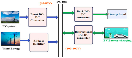
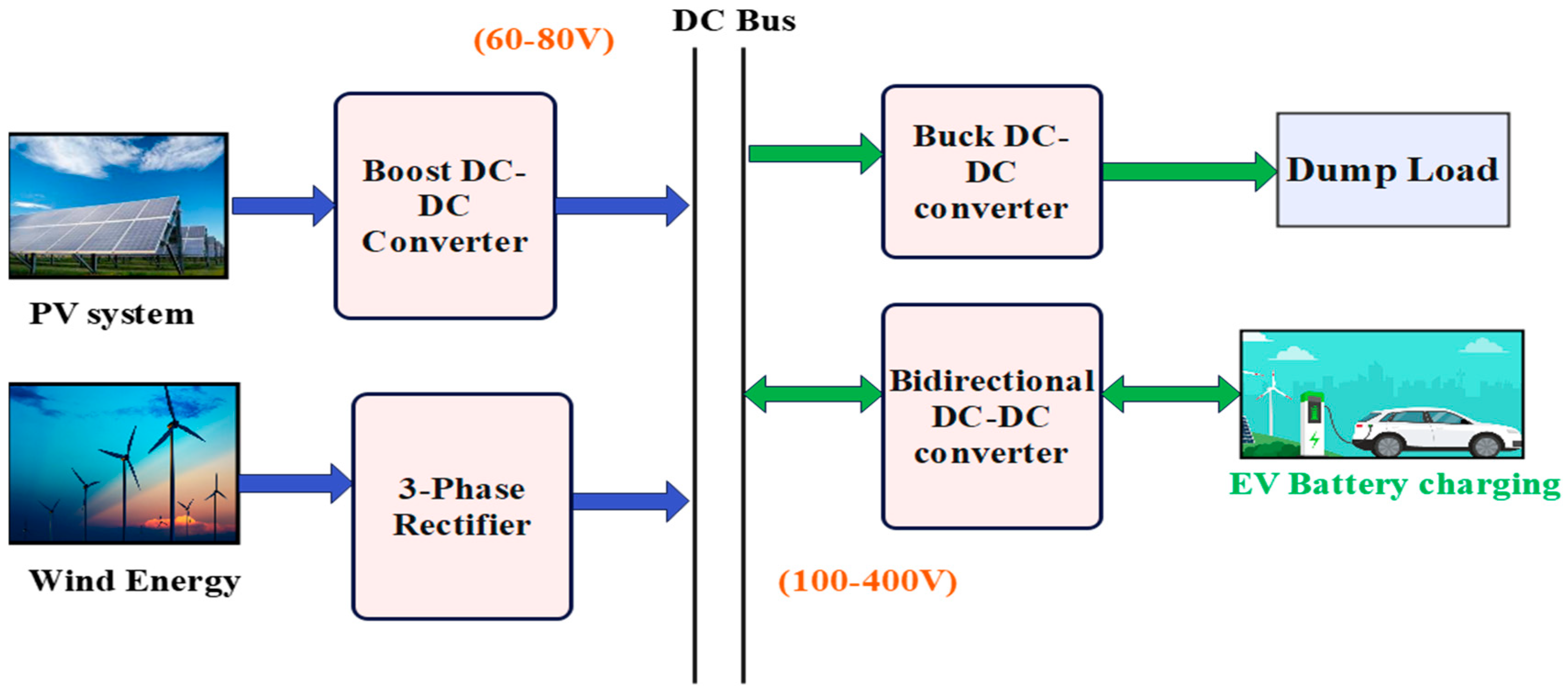
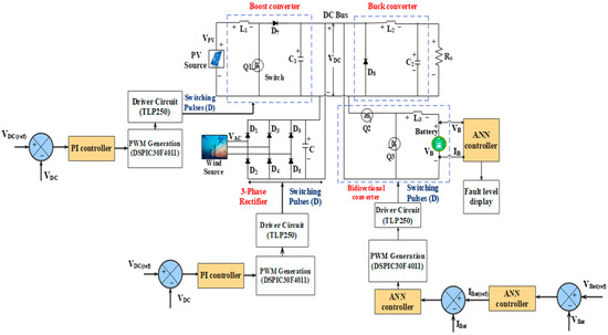
Among the various kinds of existing literature, interleaved, single-port, and bidirectional configurations with conventional controllers face limitations related to hybridizing renewable sources, efficiency, load regulation, dynamic response, and control stability. To overcome these challenges, this article introduces a new multi-source converter-based energy management system leveraging PV and wind sources to enhance energy management and load control for electric vehicle applications. The block diagram of the proposed system is shown in Figure 1.
Figure 1.
Block diagram representation of the proposed system.
Key aspects of the proposed configuration are represented as follows:
- Hybridization of multiple sources can satisfy the needs of load demand. To maintain power balance and system stability in islanded DC microgrids, dump loads are utilized.
- Improved efficiency of about 95.4% at 50% duty cycle range, maintains voltage regulation during variation in load from 1 k to 47 k, and the employment of the ANN approach can estimate the fault tolerance in the EV battery.
- Compared with the conventional controllers, the system can achieve higher power density due to its faster dynamic response and enhanced reliability through its fault detection performance as low as 5 to 15 ms.
- Elimination of high-frequency transformers and more power components can reduce control complexity and overall system cost, and their bidirectional operation can efficiently manage energy flow between the EV battery and DC bus.
- Unlike conventional works that focus on standalone controller design, this paper presents an integrated framework combining ANN-based fault detection, EMS control, and control operation under multiple modes.
The energy management system (EMS) is designed to regulate power flow among the sources, battery, and load to ensure stable and reliable operation. The EMS operates under six modes depending on source availability, battery state, and load demand. The EMS actively coordinates power flow among multiple sources, rather than relying on fixed control, which enhances system adaptability and reliability. It continuously monitors the key parameters including battery voltage (Vbat) and battery current (Ibat). Based on these inputs, the ANN-based controller identifies the system condition, detects any faults, determines the operating mode, and generates control signals for the switches. Under normal operating conditions, EMS priorities the utilization of available sources. When excess power is generated, the battery is charged, and during power deficit conditions, the battery supplies energy to the load. During the occurrence of fault, the EMS isolates the faulty component and initiates protective actions to maintain system stability and reliability.
This article can be organized into the following sections. Section 2 represents the principle and operating modes. Design guidelines, modelling, and stress calculation are presented in Section 3. ANN architecture, control strategy, and discussion of simulation results are detailed in Section 4. Section 5 presents the experimental results and discussions. Section 6 presents the discussions and the future scope of the proposed system. Finally, Section 7 concludes this article.
2. Principle and Operating Modes
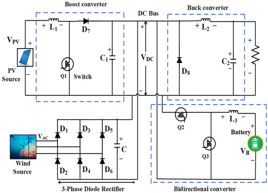
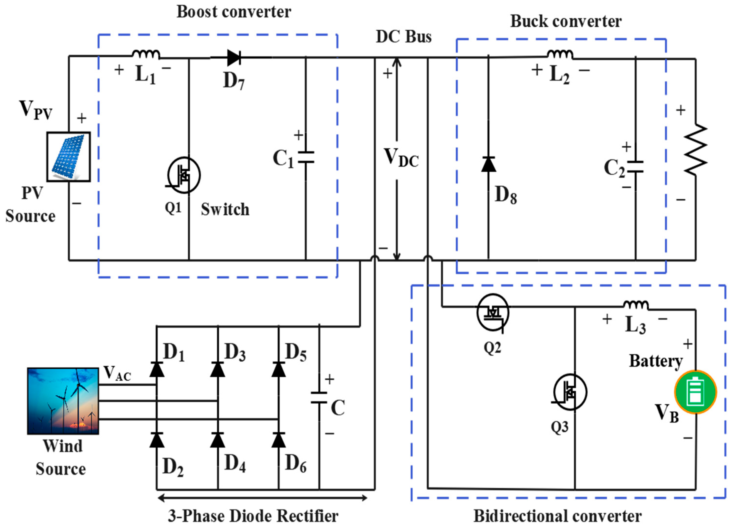
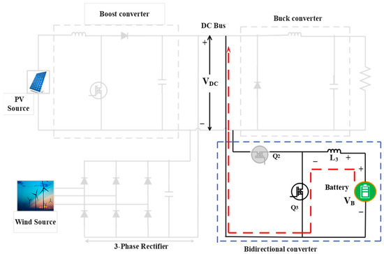
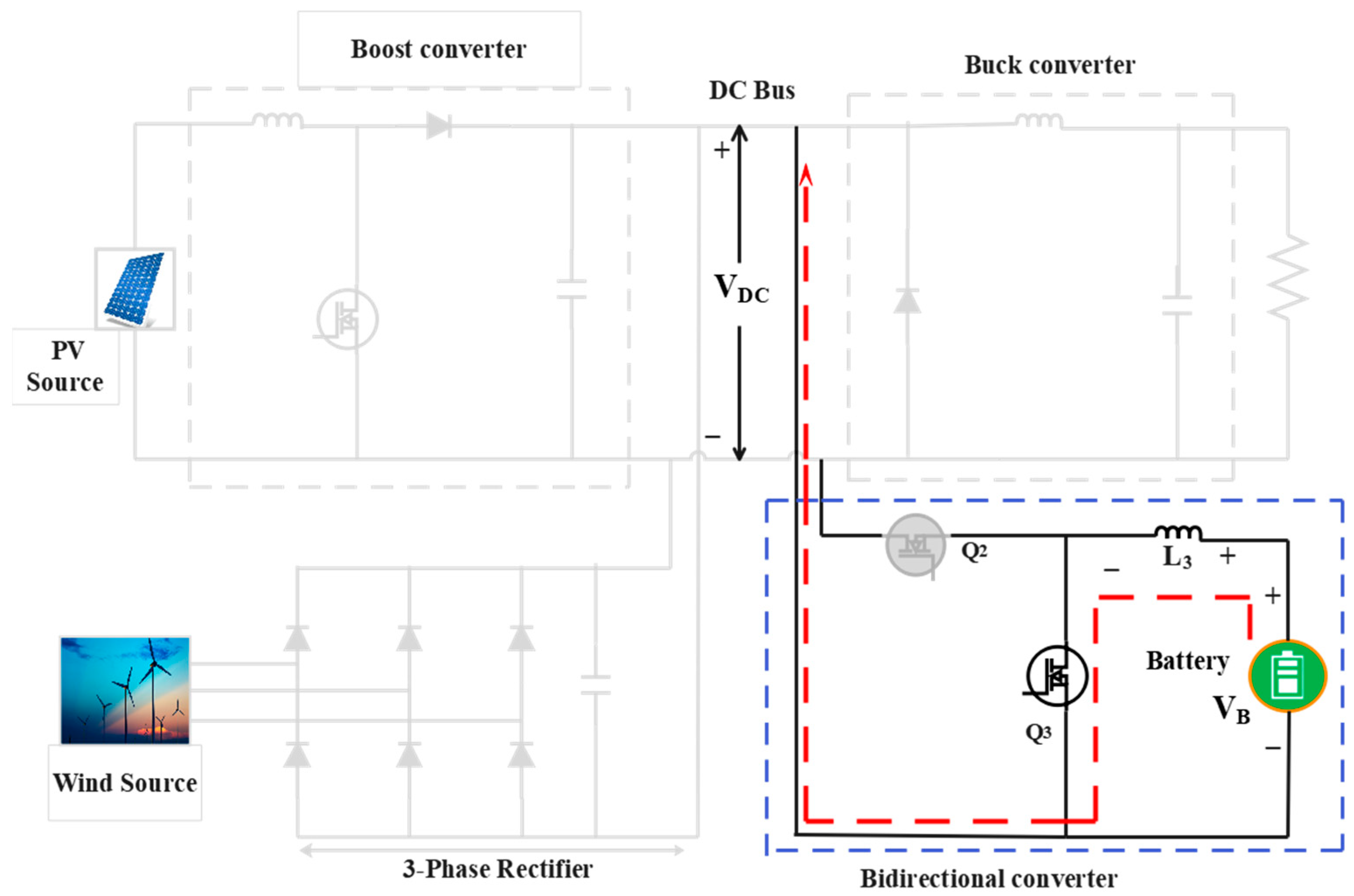
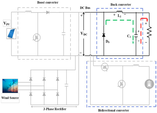
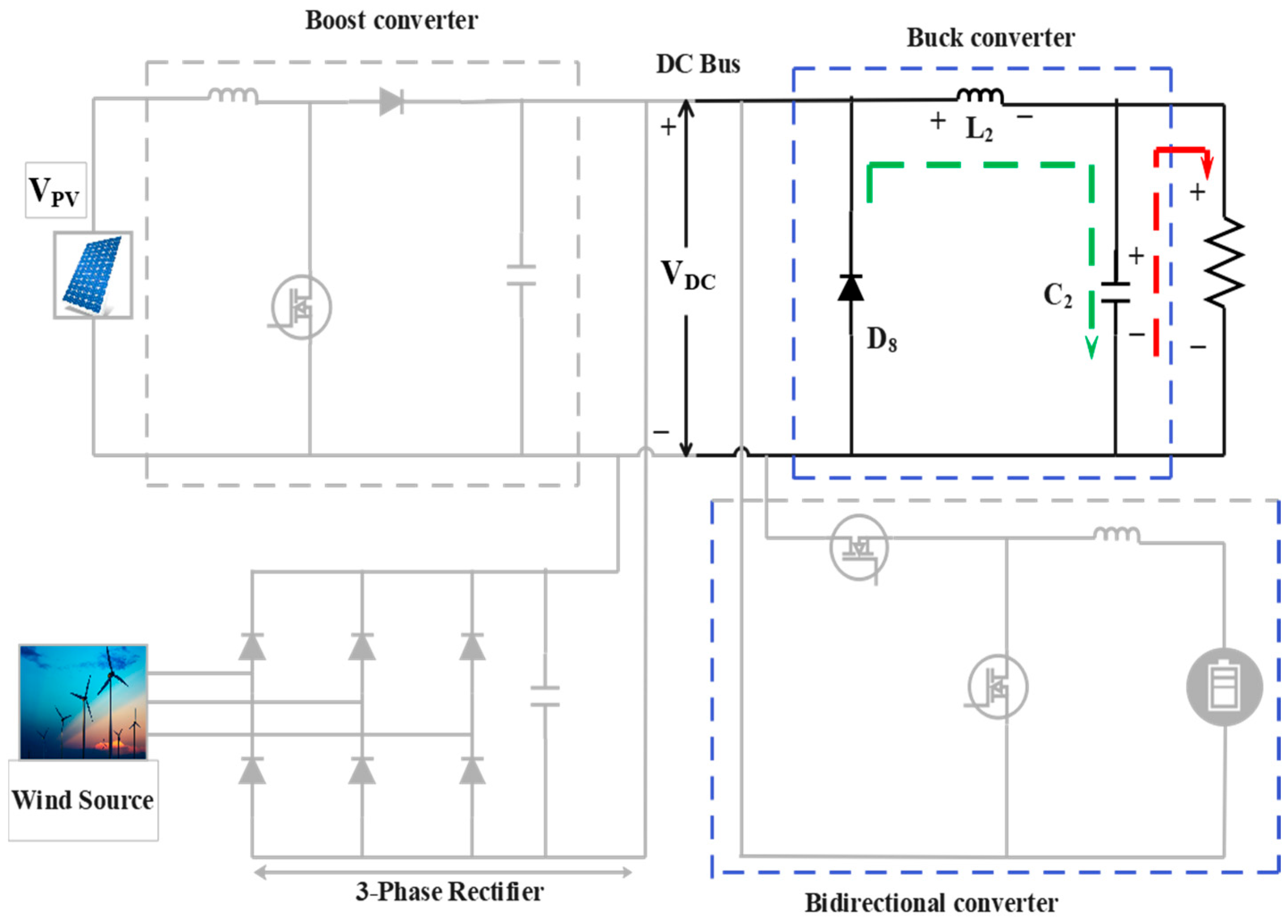
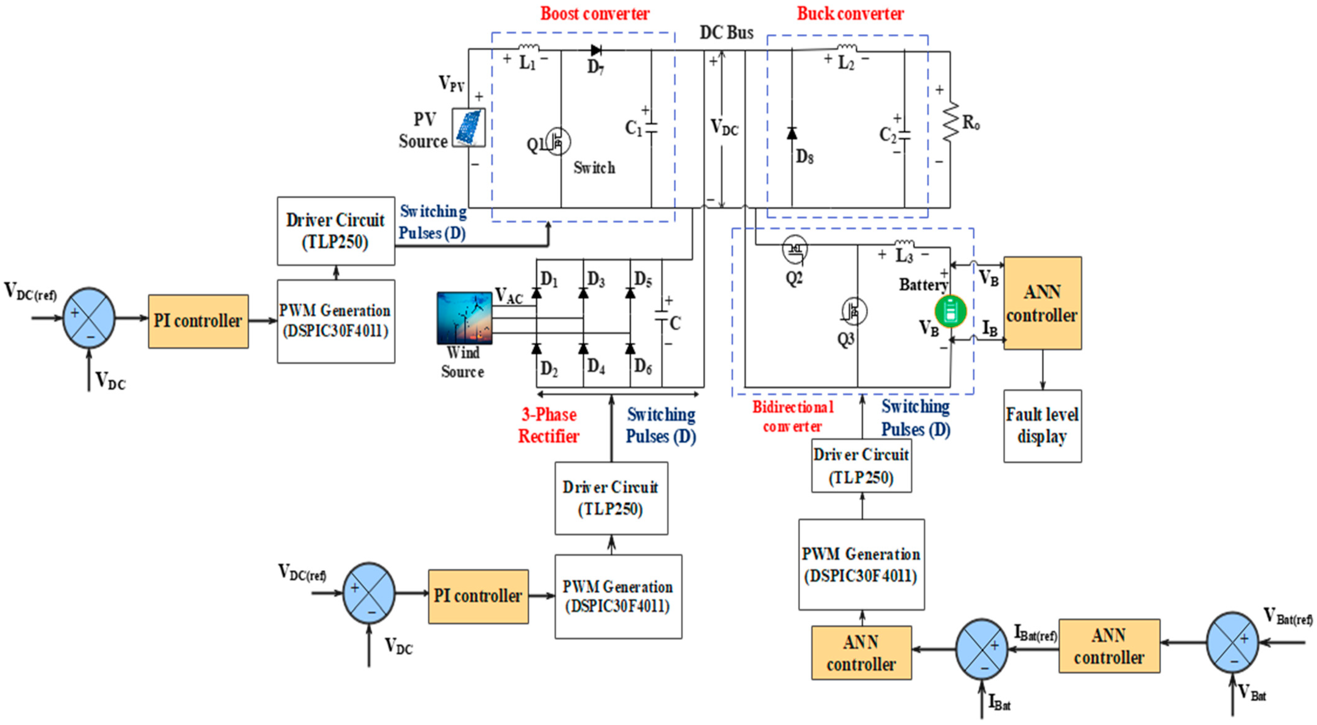
The principle of the multi-source system, comprising solar PV, wind, and a battery storage unit, and its modes of operation under CCM conditions, are elaborated in this section. The proposed configuration in Figure 2 shows a coupled structure comprising a boost converter powered by a PV system, with an inductor (L1), a single switch (Q1), a diode (D7), and a capacitor (C1). It is followed by a buck-derived converter at the load side, comprising L2, D8, and C2, which supplies the load (Ro). A bidirectional converter with a battery storage unit consists of switches (Q2, Q3) and an inductor L3, which allows the battery to either charge or discharge from the DC bus. The wind generator providing AC power is converted by a three-phase diode rectifier and then filtered by a capacitor C to provide a stable rectified DC output.
Figure 2.
Converter topology.
The system can operate in six modes. In this configuration, the PV source connects to a conventional boost to elevate the voltage to the common DC bus. The AC power from the Wind Energy Conversion System (WECS) is converted into DC by using a diode rectifier. The wind source also supplies maximum power to the DC bus. This topology also incorporates a driver circuit for control interfacing and employs a dump load for excess energy usage. An artificial neural network (ANN) controller is trained to detect faults in the EV battery and displays the fault level for timely intervention. It also enhances the system’s responsiveness under fault conditions, ensuring optimal battery life and overall system reliability during charging operations.
The DC bus functions as the main power distribution point, providing energy to auxiliary loads in an electric vehicle and to the EV battery. In this configuration, the battery charges via a bidirectional converter, which also allows power to flow back to the grid (V2G). The buck-derived converter gradually suppresses the higher voltage to a lower value and smoothens the DC output for the dump load.
2.1. Operating Modes
2.1.1. PV and Wind
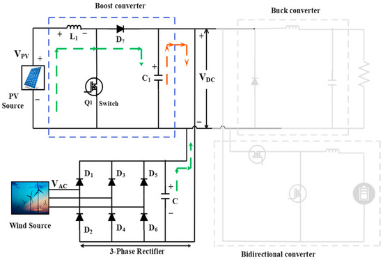
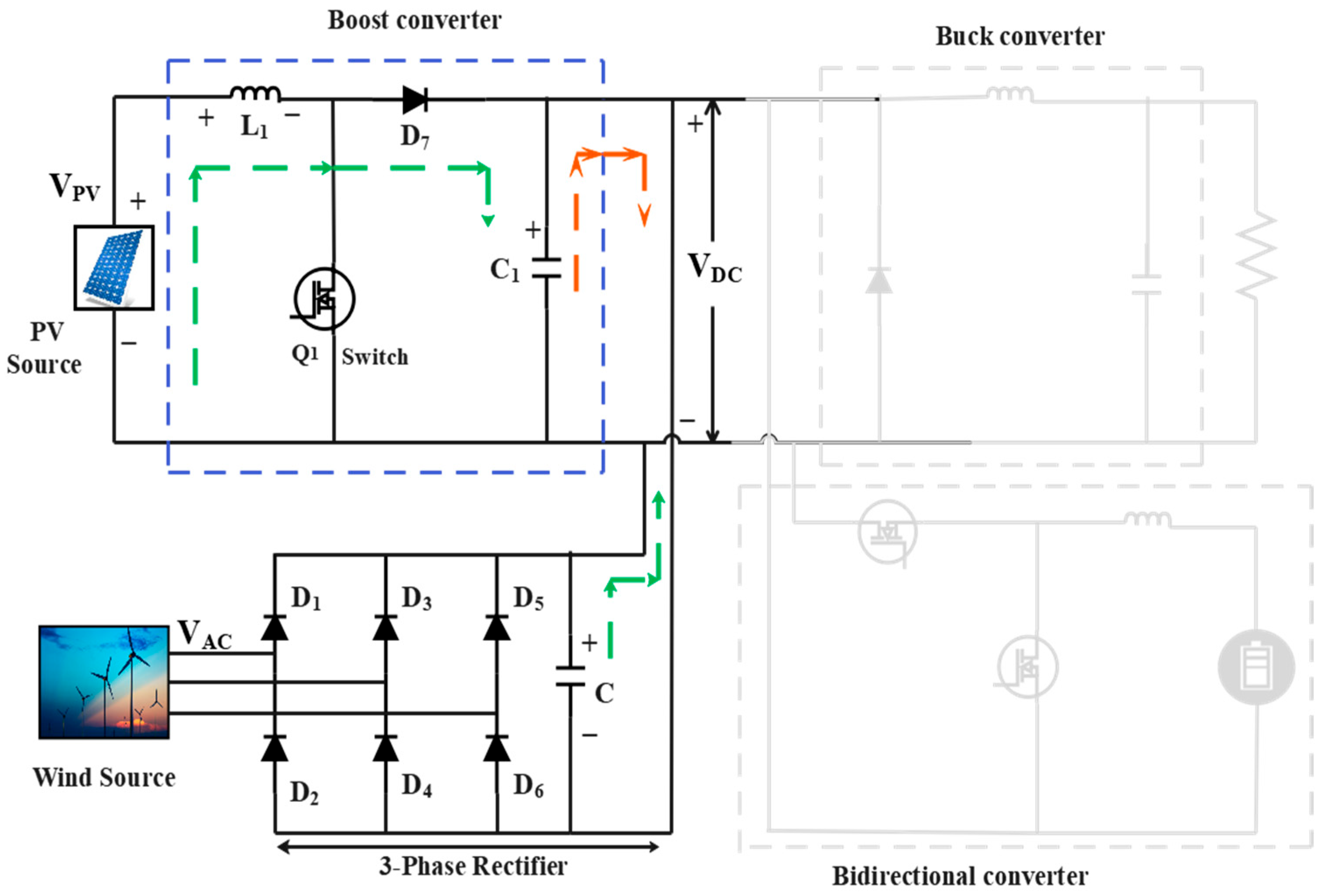
In this mode, both PV and wind sources provide power to the common DC bus. The mode of operation is presented in Figure 3. Here, the wind power is converted into rectified DC using a three-phase diode rectifier circuit.
Figure 3.
PV and wind mode.
The switch Q1 is operated to charge the inductor L1 during the On state and then discharges its energy to charge the capacitor C1, which directly feeds into the DC bus during the Off state. Capacitor ‘C’ discharges its energy to the DC bus. The charging process is specified by a green line, and the red colour specifies the discharging process.
2.1.2. PV Mode
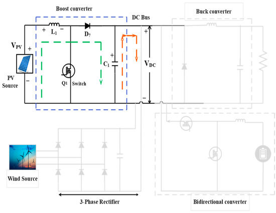
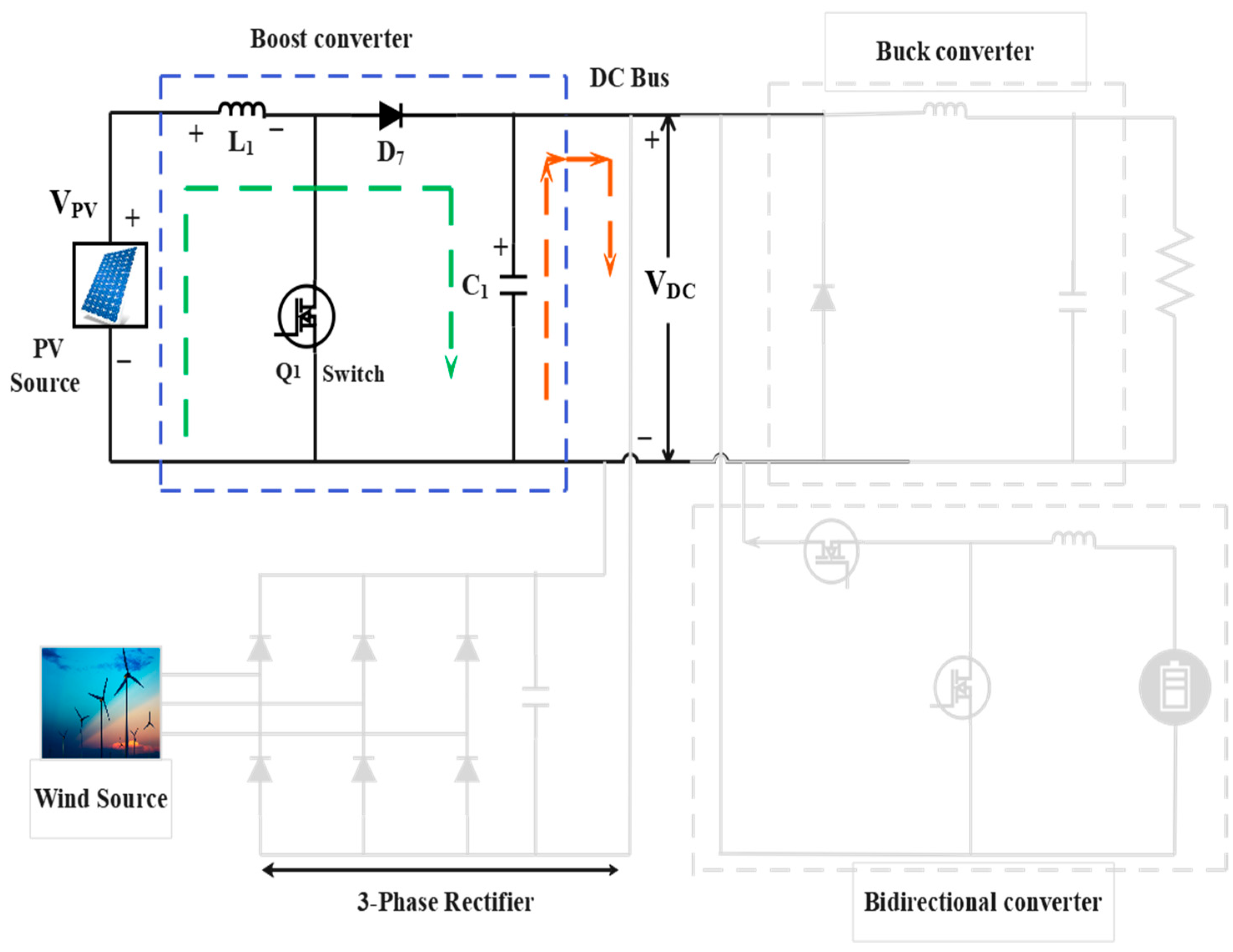
During this mode, presented in Figure 4, PV alone supplies sufficient power to the common DC bus. The switch Q1 is operated to charge the inductor L1 from the PV source during the On state and discharge its energy to charge the capacitor C1, which directly feeds into the DC bus during the Off state. Here, the charging process is specified by a green solid line, and the red colour specifies the discharging process.
Figure 4.
PV mode.
2.1.3. Wind Mode
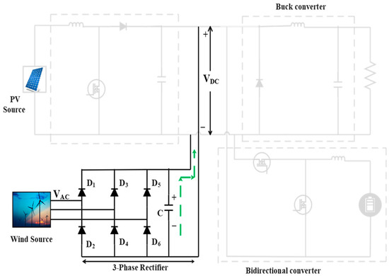
During this mode, wind alone supplies a rectified DC power to a common DC bus via a boost converter. Capacitor ‘C’ stored energy flowing to the DC bus during the Off state. Here, the green line indicates the charging process. In this condition, the PV system remains disconnected. The operating mode is presented in Figure 5.
Figure 5.
Wind mode.
2.1.4. Battery Charging Mode
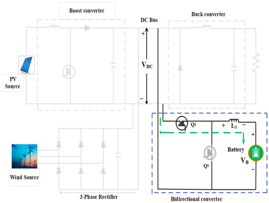
In this mode, shown in Figure 6, the switch Q2 is operated, and Q3 remains in the Off state, where the bidirectional converter allows the inductor L3 to charge from the DC bus. L3 stored energy is discharged to the battery and operates it as boost mode.
Figure 6.
Battery charging mode (G2V).
2.1.5. Battery Discharging Mode
During this mode, switch Q3 is operated, and Q2 remains in the Off state, where the energy stored in inductor L3 discharges from the battery to the DC bus. During this period, the system operates in a buck mode. This operating mode is presented in Figure 7.
Figure 7.
Battery discharging mode (V2G).
2.1.6. DC Bus Grid Fault or Islanded Mode
During this mode, the buck converter reduces the higher voltage from the grid source to a lower voltage and smoothens the DC output to feed the dump load. The inductor L2 charges during the On state and discharges during the Off state to charge the capacitor C2, respectively. The mode of operation is presented in Figure 8. The detailed switching look-up table for all modes is presented in Table 1.
Figure 8.
Grid fault or islanded mode.
Table 1.
Switching look-up table under all modes.
3. Design Guidelines, Stress Analysis, and Modelling
The inductors and capacitors are designed by considering the ripple factors and voltage and current flows across them. The comparative analysis of ripple factor specifications is detailed in Table 2.
Table 2.
Comparative analysis of the ripple factor specifications.
3.1. Design Considerations
3.1.1. Parameter Design on Inductors
During the On state, by applying the Volt-Sec balance principle, inductances are designed by considering 20% ripple at 50 kHz, given as
Here, is the switching frequency, is the inductor current ripple, vs. is the source voltage, and D is the duty cycle, respectively.
3.1.2. Parameter Design on Capacitors
By applying the Amp-Sec theory, capacitances are designed by considering the capacitor voltage ripple as 10% given by the following Equation (2),
3.2. Power Switch Selection
To determine the cost and efficiency of the converter, switch voltage is an essential factor. Here, the load voltage is always kept lower than the switch voltage, but equals the capacitor voltage. The expression for the switch voltage can be represented as,
3.3. Modelling of PV Systems, Irradiance Variation, and Wind Energy Source
The PV system is modelled using a single-diode equivalent circuit, in which irradiance variation is introduced through a photo-generated current proportional to the solar irradiance. The wind source is modelled using a standard aerodynamic turbine model where wind speed variations are introduced dynamically. The PV system model consists of a current source, a diode, a series resistance, and a shunt resistance.
The PV module output current can be represented by the following Equation (4),
Here, Rs is the series resistance, Rsh is the shunt resistance, V is the voltage, I is the current, n is the diode ideality factor, Io is the diode’s reverse saturation current, and Ns is the number of cells in series. The modelling of irradiance is computed through the photo-generated current, which is directly proportional to the solar irradiance. The generated current can be represented as,
Here, G is the instantaneous solar irradiance, Gref is 1000 W/m2, T is the temperature, and αT is the temperature coefficient of current. Meanwhile, the wind source is modelled by using a standard aerodynamic turbine model, where the mechanical power generated is expressed as,
Here, is air density, is tip-speed ratio, Cp is power coefficient, is blade pitch angle, and w is wind speed.
3.4. Stress Analysis Calculation
The voltage and current stress analysis of all switches and diodes is detailed in this section. Current and voltage ratings of all the power components are derived from this analysis. Voltage and current stresses across the switches and diodes can be calculated during the switch-off state under steady-state operation. A margin analysis presented in Table 3 confirms that all components can operate within safe limits. Table 4 shows the voltage and current stresses across all power components in various modes. In the following table, VDC represents DC voltage, IPV stands for PV current, ILoad is load current, Ibat is battery current, IAC is AC current, and VAC is AC voltage.
Table 3.
Stress and margin analysis of key components.
Table 4.
Voltage and current stress analysis under all modes.
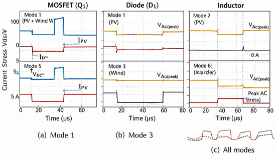
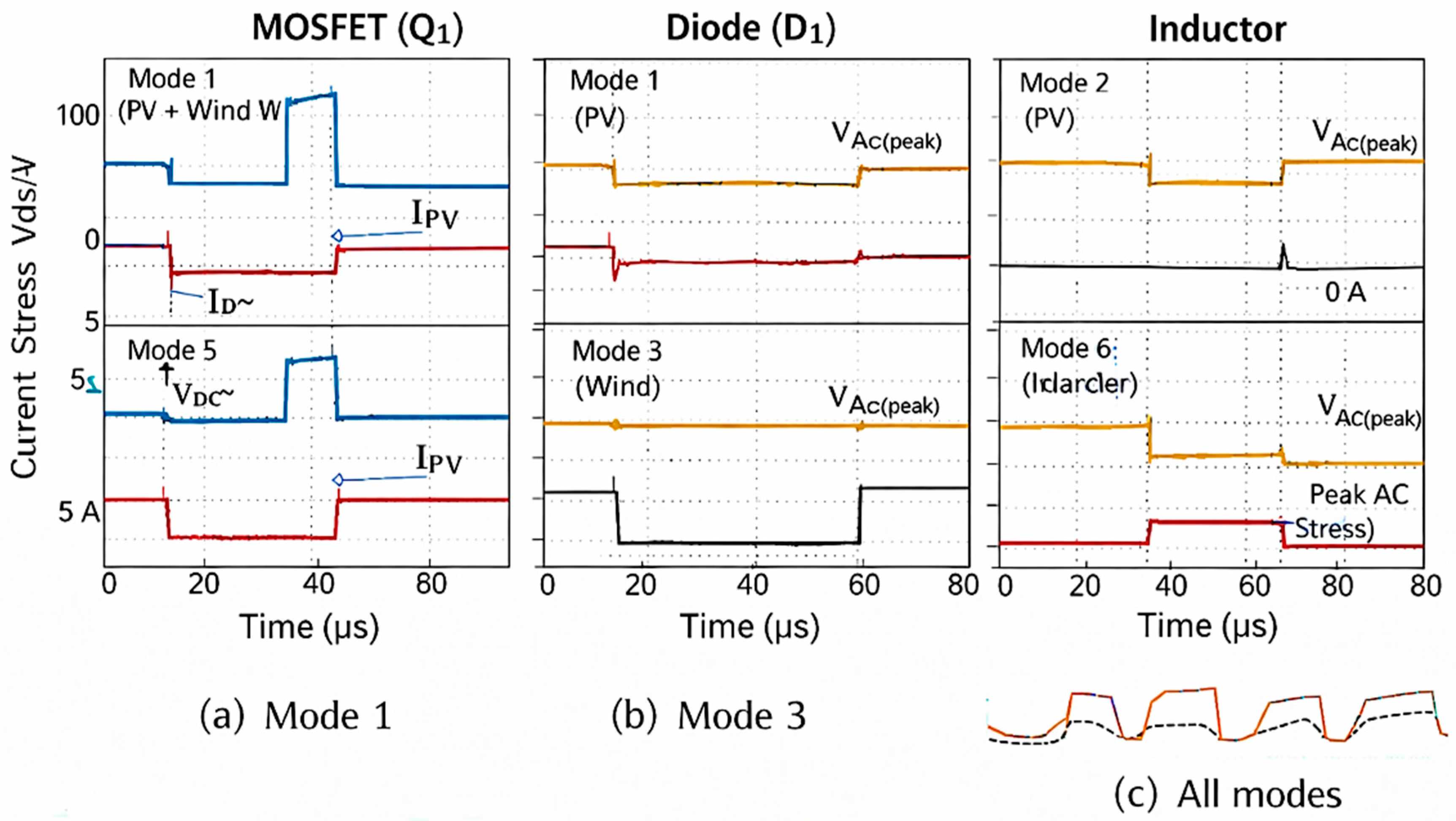
The maximum voltage stress equals the DC-link voltage, while the current stresses are estimated based on inductor currents. Peak values are determined by considering the inductor current ripple under CCM, ensuring proper component rating selection. The comparison of voltage and current stress waveforms of power components (MOSFET, diode, and inductor) under different operating modes, validating the stress analysis, is presented in Figure 9. The waveform confirms that the voltage stress remains largely constant, while current stress is strongly dependent on the operating mode. The diode stress depends on source availability and mode. Furthermore, the inductor current remains continuous under all operating modes, confirming stable operation in CCM. This comparative analysis demonstrates that the component stresses are mode-dependent and remain within safe operating limits. The selected devices are higher than the maximum observed stresses, ensuring reliable performance under steady-state and transient conditions.
Figure 9.
Comparison of voltage and current stress waveforms of key components under different operating modes.
Voltage and Current margin can be expressed as,
4. Control Algorithm and Simulation Results
4.1. Artificial Neural Network (ANN) Control Strategy
An artificial neural network (ANN) is generally considered an artificial intelligence (AI) tool inspired by the structure and function of neurons in the human brain. It is primarily applicable for predicting the performance of non-linear systems. For analyzing dynamic modelling, regression problems, system identifications, and fault detection, an ANN strategy is commonly employed. The proposed system incorporates a multi-layer feedforward neural network (NN), which is applied for fault estimation, where the elements of the NN are divided into layers. The ANN architecture comprises input layers, hidden layers, and output layers. The finite accuracy of the model can be improved by increasing the hidden layers, based on its requirements. The equation for the weighted summation of the inputs in the ANN structure model can be represented as follows,
Here, Xi represents the input data of the NN, and Wi represents the weightage and b the bias vector component. The activation function is applied to get an accurate output based on its desired input. In feedforward networks, the output layer cells are applied as the input of the next layer. The network output is finally computed between the hidden and output layers. The backpropagation technique is carried out to generate a decent output by reducing the error signal. This method is used to train the weights of the multi-layer feedforward network. If the network has ‘n’ inputs, ‘m’ neurons, and one output, the ANN backpropagation structure can be stated as follows,
An output signal can be computed by the following Equation (9) as,
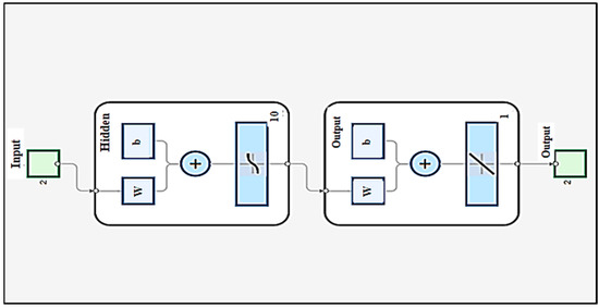
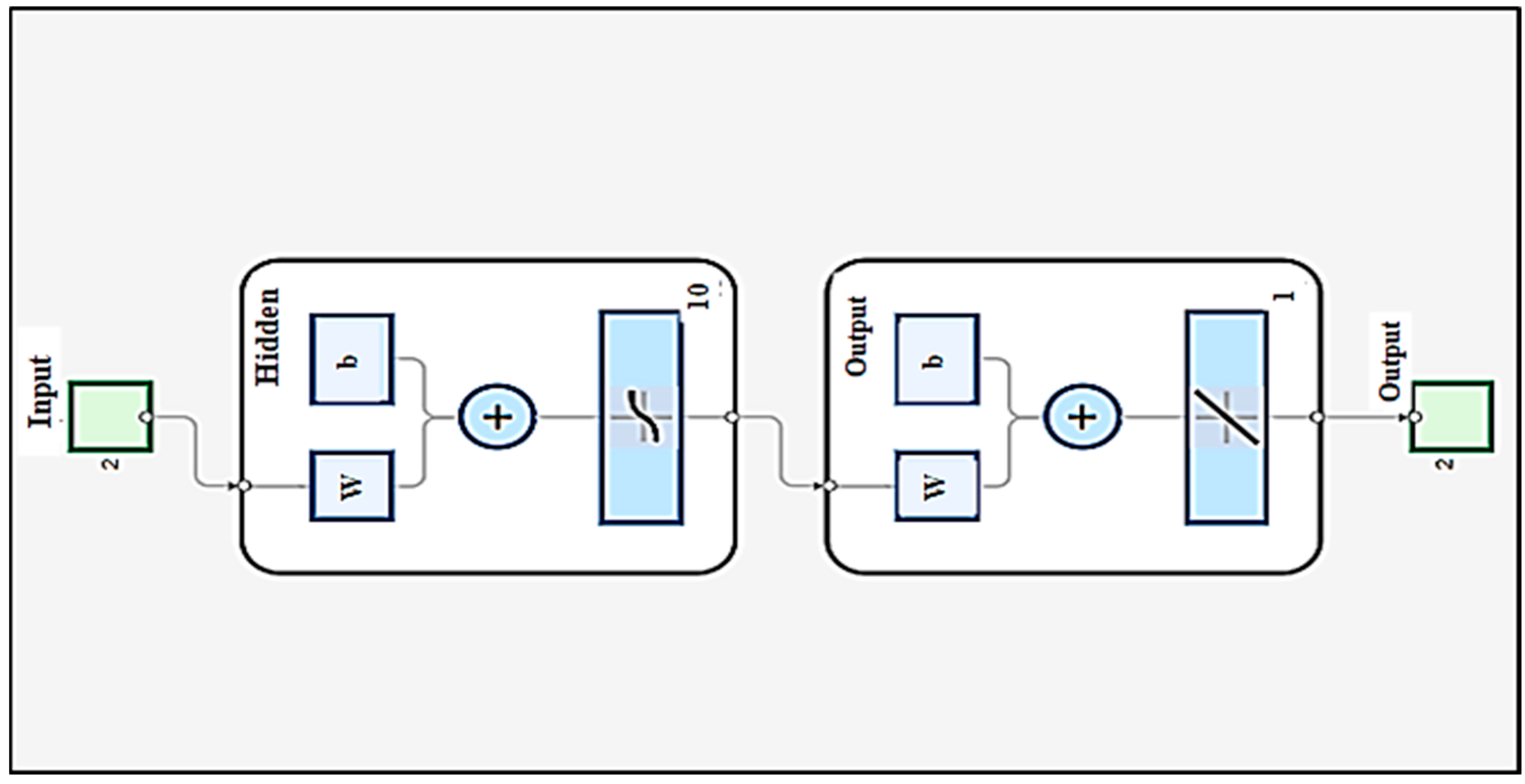
Here is the input factor and and are hidden layers of output and input. ‘b’ represents the bias factors of the hidden and output layers, respectively. ‘w’ represents the connection weights and ‘y’ represents the final computed output. The layered structure of the proposed feedforward artificial neural network algorithm is presented in Figure 10. It comprises 2 input neurons, one hidden layer with 10 neurons, 1 output neuron, and its sigmoid function can be represented as,
Figure 10.
MATLAB feedforward ANN structure for the system.
The ANN receives two input variables, shown as a green labelled block, and passes them directly to the hidden layer without any transformation. The hidden layer can capture a nonlinear relationship between the input and output. The output layer performs the weighted summation of the hidden-layer outputs used in regression problems to provide continuous output values. This ANN approach is incorporated in a bidirectional converter to analyze the battery-side fault detection. The controller receives battery voltage and current as training data sets. After calculating the bias factors and weights, the well-tuned ANNs can be implemented in the system. The mean squared error (MSE) and the correlation coefficient (R) should converge from 1 to 0 to achieve accuracy. Here, (ref) is the desired value, and (t) is the estimated value.
The cost function can be represented as,
Here, is the voltage regulation error, , and is the battery stress. The control objective is formulated through a cost function that minimizes DC bus voltage deviation, power mismatch, and battery stress. The ANN does not directly minimize the cost function but assists in identifying system conditions and faults, enabling the EMS to make optimal decisions based on predefined objectives. The system uses real-time parameters of battery voltage (Vbat) and battery current (Ibat) as primary inputs for ANN-based fault detection. These parameters represent the system state and are used for decision-making under both normal and fault conditions. To evaluate the ANN-based fault detection for each fault and operating condition, the response time of the fault detection and the steady-state fault estimation error can be represented by the following Equation (11),
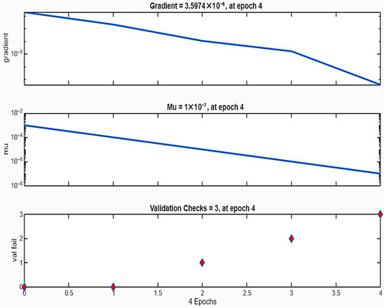
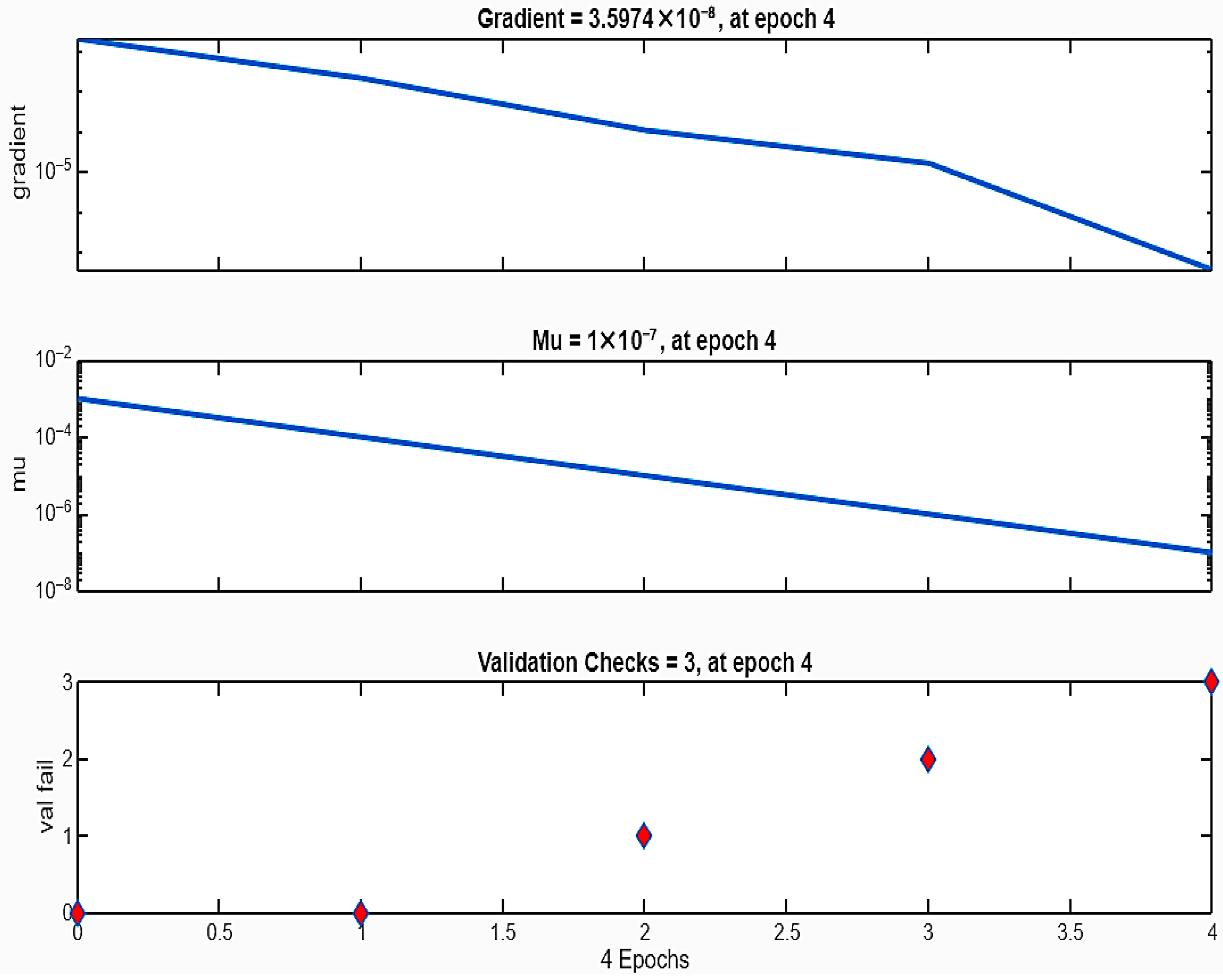
Here, n represents the number of samples. ANN inputs and outputs are used to estimate data, trained, and then validated for the converter’s performance. The backpropagation algorithm is employed, which has two inputs in the input layer, 10 hidden neurons in the hidden layer, and the generated output in the output layer. Their targets are divided into training, validation, and testing sets at 70%, 15%, and 15%, respectively, over 4 epochs. The training process reached a minimum gradient of 0.0201 using the Levenberg–Marquardt algorithm. Here, the training gradient decreases steadily, while the damping parameter (µ) is reduced, which indicates effective learning. The convergence characteristics, including gradient reduction and performance validation, are illustrated in Figure 11. The limited number of validations was reached at 4 epochs. The mean squared error (MSE) was 2.961 × 10⁻⁴ for training, 4.100 × 10⁻⁴ for validation, and 1.568 × 10⁻⁴ for testing. The dataset used for training the ANN consists of 1000 samples, which can be divided as,
Figure 11.
Trained data of the ANN structure.
- Training set: 70% (700 samples);
- Validation set: 15% (150 samples);
- Test set: 15% (150 samples).
This division ensures proper training, validation, and generalization of the ANN model. The converter operates at a switching frequency of 50 kHz, and the system signals are sampled at the same rate to observe switching dynamics effectively. An appropriate feature extraction window of 100 samples (2 ms) can be used, where each window represents one data instance for the ANN. Hence, the total dataset contains 1000 such instances for the datasets.
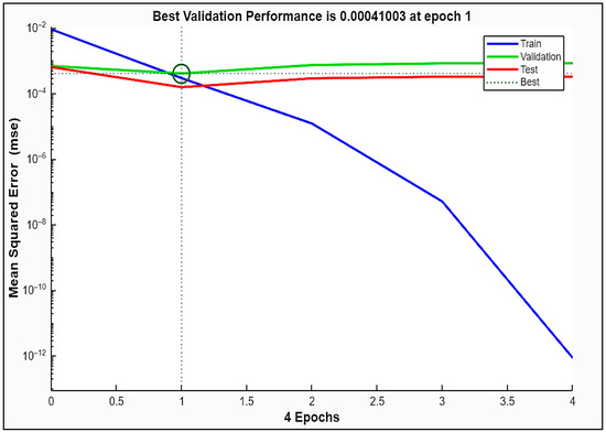
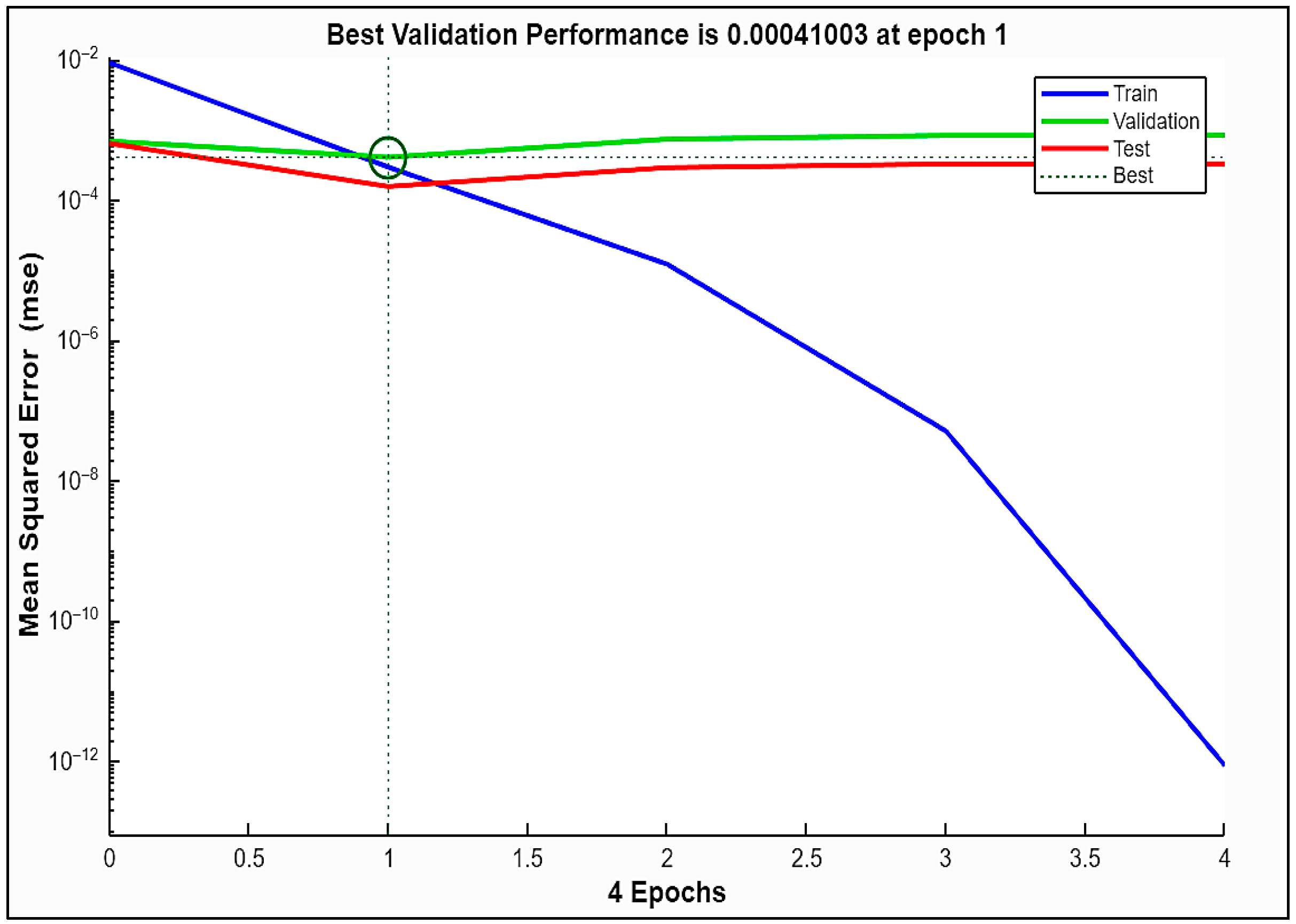
The neurons in the hidden layer can be regulated, and the ANN’s performance curve is shown in Figure 12, demonstrating stable convergence and generation capability. Here, the X-axis refers to the number of training epochs, the Y-axis refers to mean squared error (MSE), the blue line refers to training error, the green line refers to validation error, and the red line refers to test error. The dashed vertical line with a circle refers to the epoch with the best validation performance. The best validation performance of 0.00041003 is achieved at epoch 1, after which early stopping is triggered based on validation checks to prevent overfitting. This epoch is observed as an optimal point. The training process is carried out for 4 epochs, and the performance is evaluated using the mean squared error (MSE) criterion. The training error decreases steadily with increasing epochs, which indicates that the ANN is continuously fitting to the increasing training data. The validation and test errors can exhibit a slight increase, indicating the divergence of overfitting. The network parameters corresponding to epoch 1 ensure the robust performance of the system.
Figure 12.
Performance curve of the system using an ANN structure.
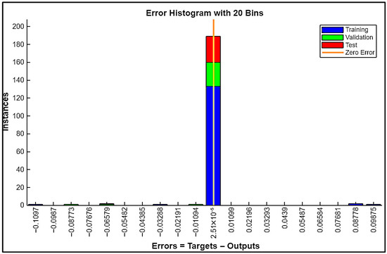
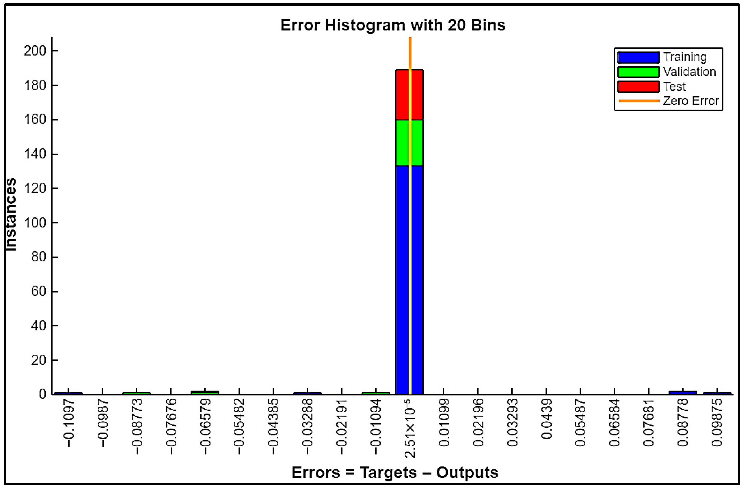
An error can be computed between the difference in the targets and outputs. The y-axis refers to the number of instances. The distribution of prediction errors across training, validation, and testing can be represented by a histogram plot shown in Figure 13. The error histogram indicates that the neural network output matches the target values.
Figure 13.
Histogram plot of the ANN training.
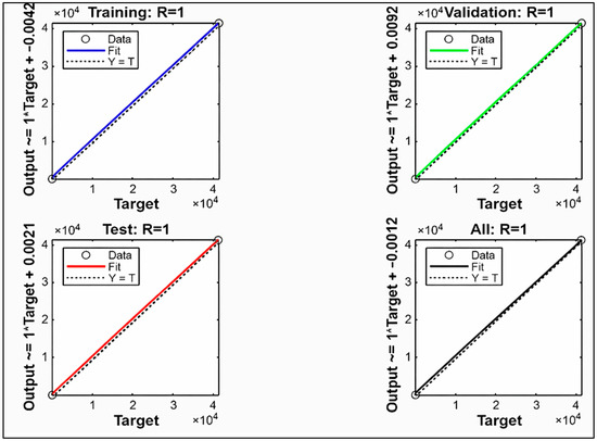
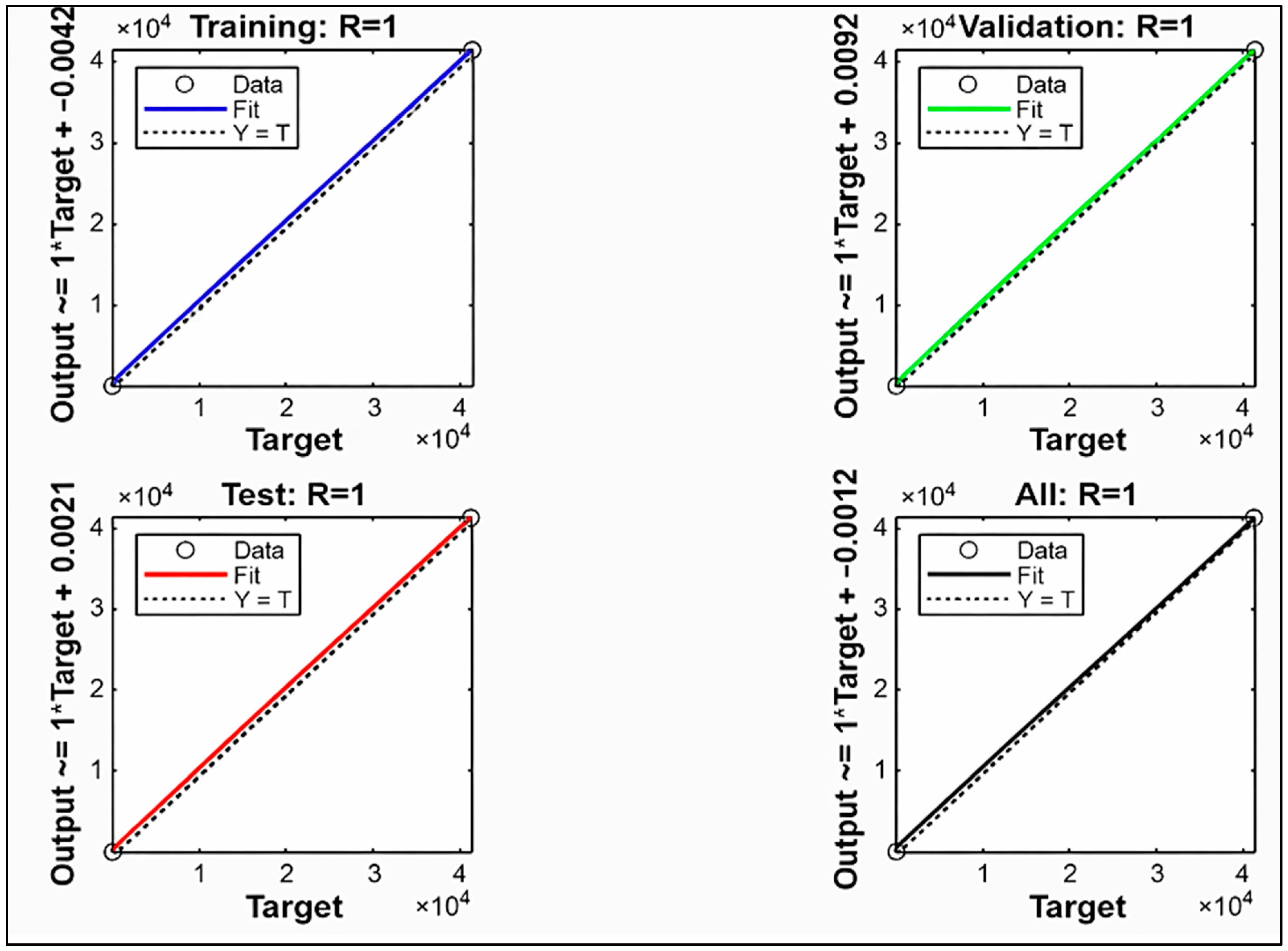
Finally, the trained regression plot using ANN structure is displayed in Figure 14, which proves that the network is trained using the Levenberg–Marquardt algorithm, owing to its fast convergence and suitability for nonlinear systems. The value of R indicates that the network performs with zero error in predicted outcomes for each corresponding target. Here, Y = T dotted line represents the ideal conditions where the predicted outputs exactly match the target values confirms the high accuracy and effectiveness of the proposed system.
Figure 14.
Regression plot using ANN.
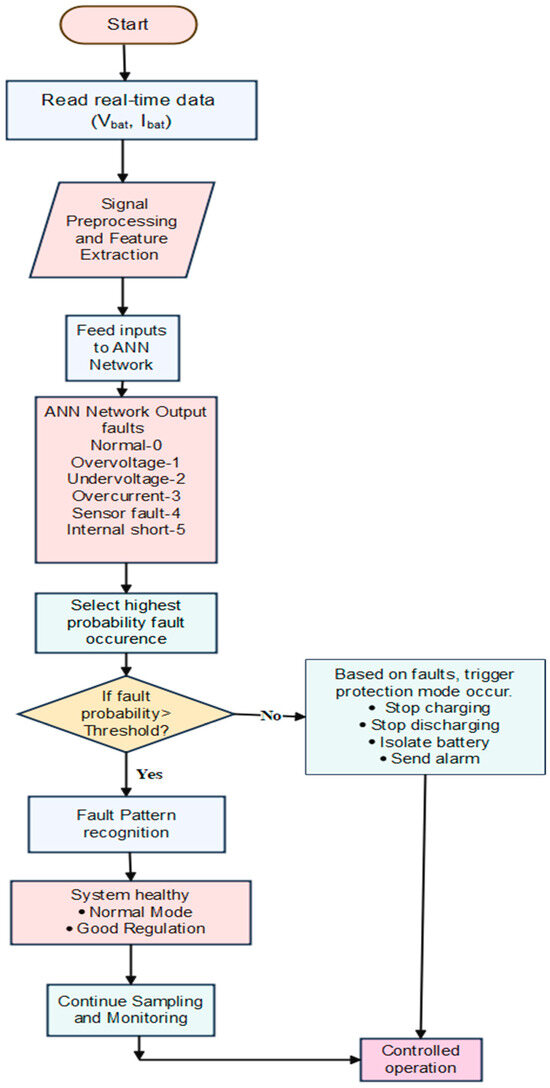
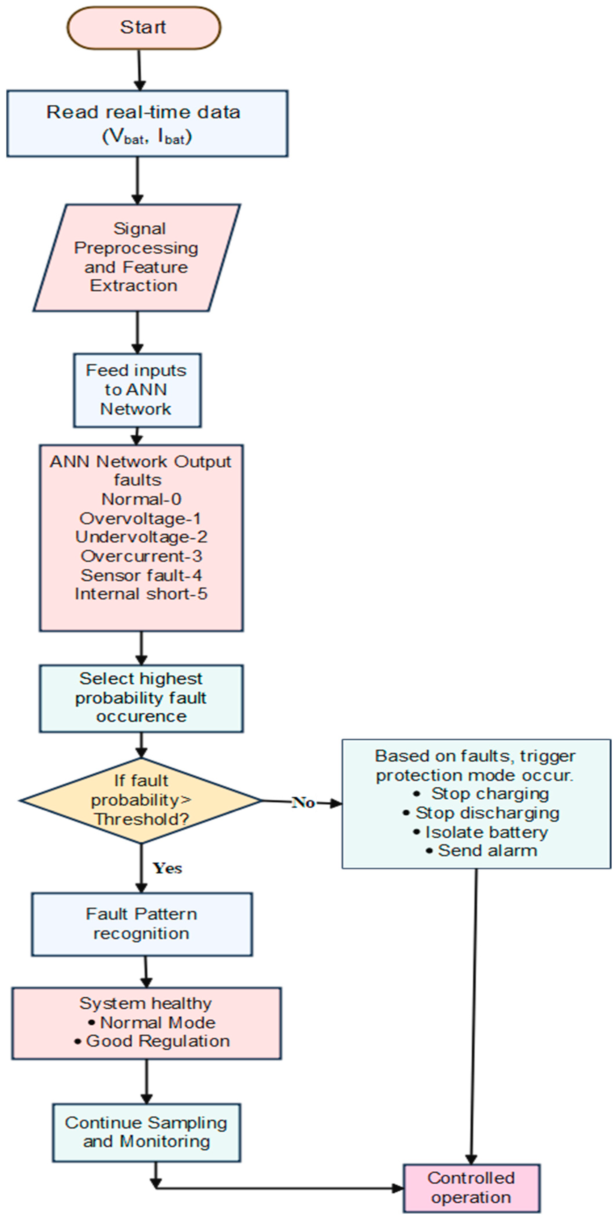
The detailed flowchart of the ANN structure for the proposed system is represented in Figure 15. The ANN structure is designed for multi-class fault classification using two input features: battery current (Ibat) and battery voltage (Vbat). The ANN is trained to classify the system into the following operating conditions,
Figure 15.
Flowchart of ANN-based battery fault tolerance algorithm.
Class 0: Normal operation
Class 1: Overvoltage fault
Class 2: Undervoltage fault
Class 3: Overcurrent fault
Class 4: Sensor fault
Class 5: Internal short circuit fault
The dataset is labelled according to predefined operating conditions and fault scenarios. Fault conditions are created through simulation and experimental testing by introducing disturbances such as voltage variations, current surges, and sensor anomalies. Each data instance is assigned a class label that corresponds to the observed system condition. The ANN produces a probability vector for various fault classes. A fault is identified when the probability for a specific fault exceeds a set threshold of 0.8. If all class probabilities stay below this threshold, the system is considered to be operating normally. This threshold-based method ensures reliable fault detection while reducing false alarms.
In the proposed approach, the ANN controller identifies different fault conditions by using the measured battery current (Ibat) and battery voltage (Vbat) as input features. During the preprocessing stage, features such as voltage deviation, current deviation, and transient changes are extracted from these signals. During the training stage, these parameters enable the ANN controller to analyze distinct patterns associated with each fault type. Here, an internal short circuit causes a rapid voltage drop combined with an increase in current, while a sensor fault causes inconsistent signals or discontinuities between voltage and current. From these labelled training datasets, the ANN can classify and detect the corresponding fault based on the highest probability output.
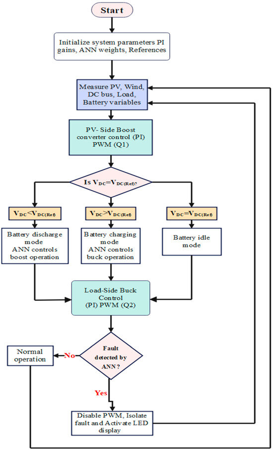
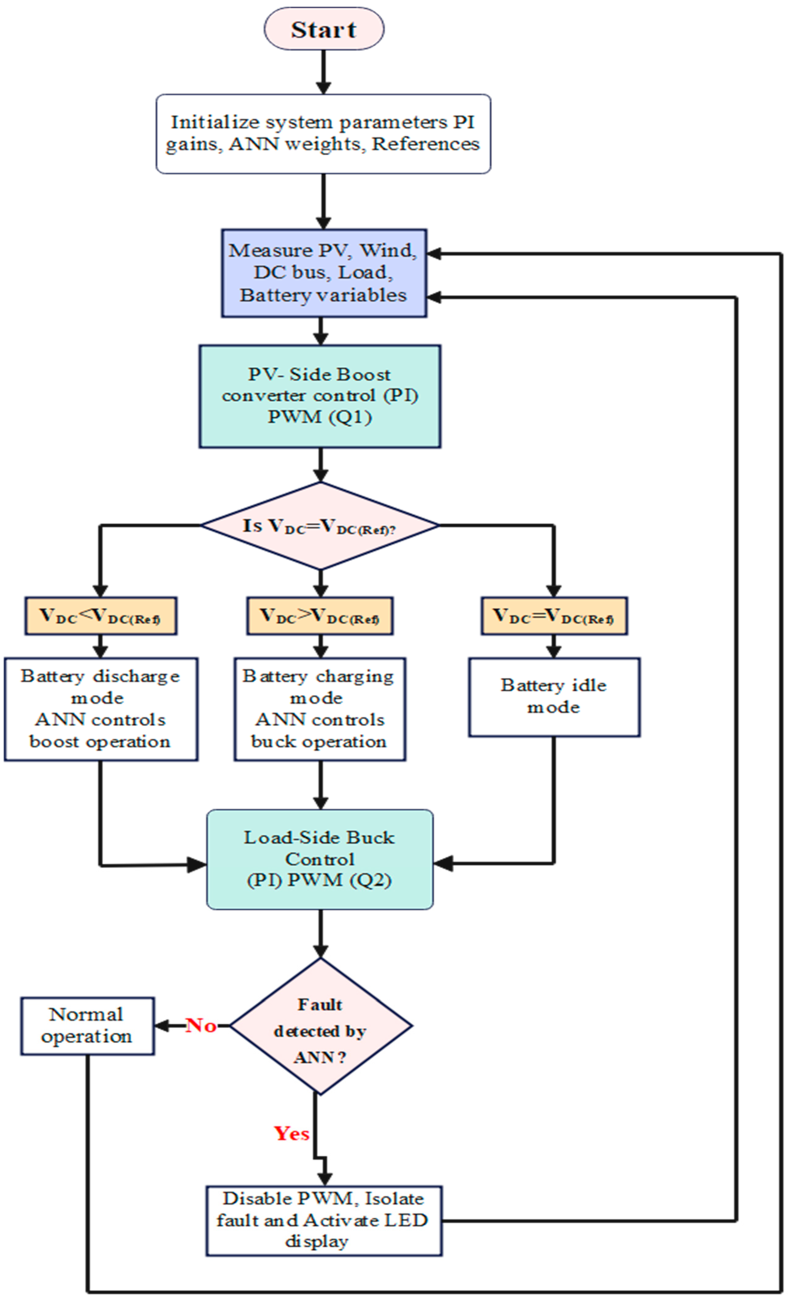
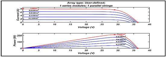
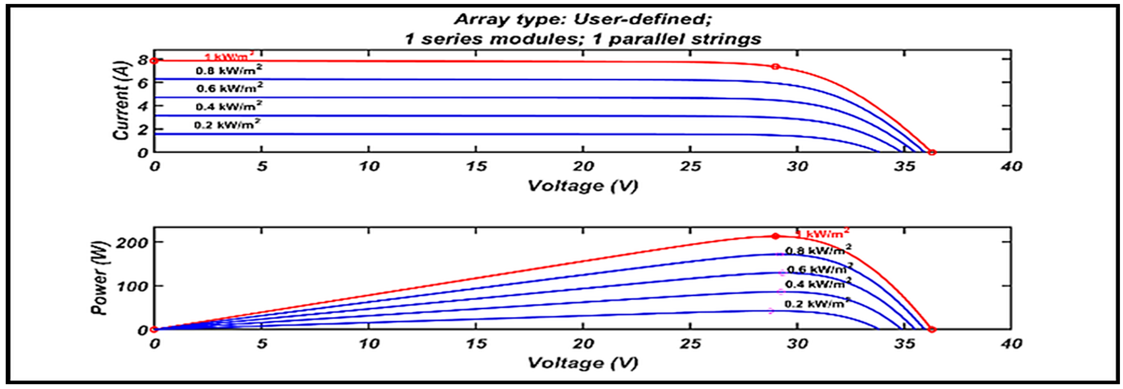
Figure 16 illustrates the schematic of the overall control strategy of the configuration. Between the reference input and the control variable at every sampling instant, an error signal is computed. Using a trial-and-error method, it computes a generalized control action, which is a switching pulse (D) for Q2 and Q3 of the converter. The controller monitors battery voltage and current parameters and displays a fault level output, indicating the severity or type of fault. It does not apply to monitoring DC grid parameters directly. The DC grid fault detection mechanism uses conventional relay-based methods to monitor voltage and frequency thresholds. The controller initiates the switch operation for mode 6 to isolate the load and maintain the power supply via the buck-derived converter. A conventional PI controller is integrated into the 3-phase rectifier circuit and to the boost converter to compare the reference DC voltage with the actual voltage, adjusting the PWM duty cycle to maintain the desired DC voltage level. Figure 17 represents the flowchart of the overall control algorithm for the proposed configuration. The battery energy storage system (BESS) specifications are shown in Table 5. The solar PV system specifications are tabulated in Table 6, and its performance characteristics curve is shown in Figure 18. Table 7 represents the specifications of the simulation parameters.
Figure 16.
Schematic controller strategy of the proposed system.
Figure 17.
Flowchart of the overall control algorithm.
Table 5.
Specifications of battery energy storage systems (BESSs).
Table 6.
Solar PV system parameters measured at standard test conditions of irradiance 1000 W/m2, AM 1.5, and cell temperature at 25 °C.
Figure 18.
Current and voltage characteristics curve of the PV system.
Table 7.
Simulation parameter specifications.
4.2. Simulation Results
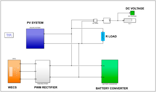
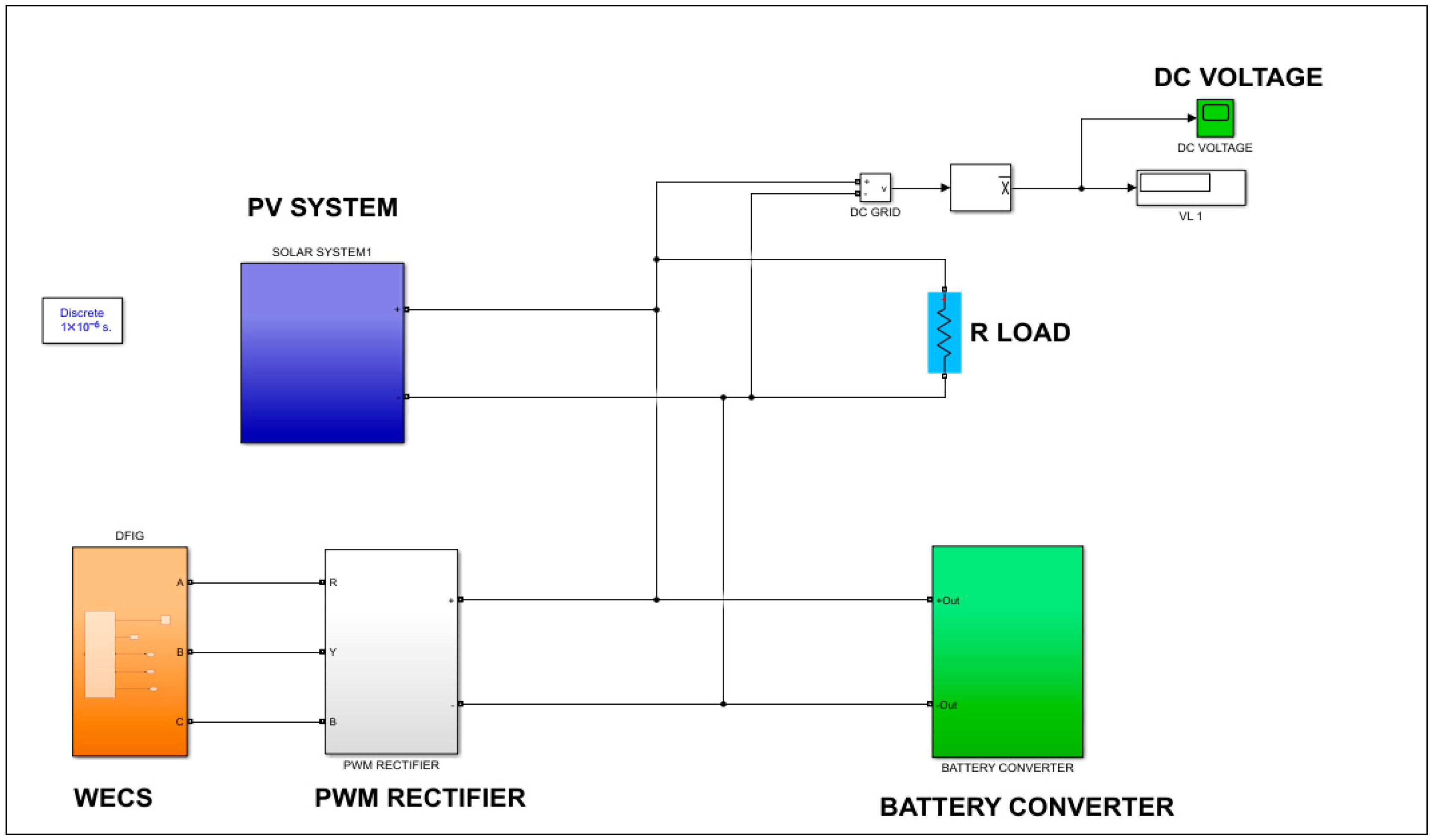
The simulation results are generated and executed using MATLAB Simulink and presented in this section. Figure 19 represents a Simulink model including a PV system, a wind source, a rectifier circuit, a battery storage system, and a DC microgrid. PV source is integrated with a boost structure, controlled by a PI controller, which simulates PV’s dynamic behaviour at various temperature and irradiance conditions to maximize the power output.
Figure 19.
Simulink model of the system.
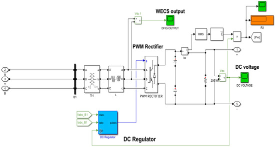
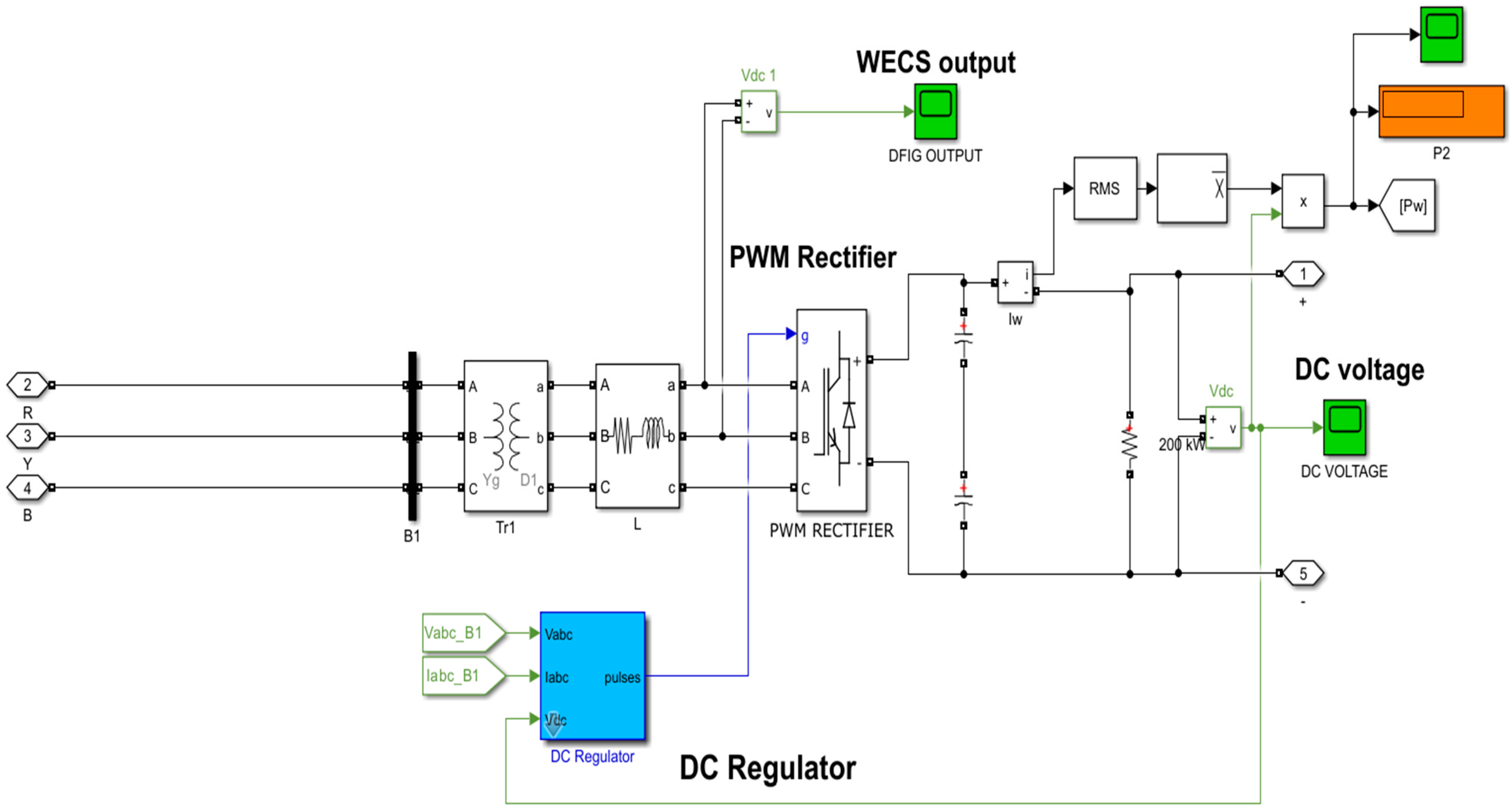
The Simulink model of a wind energy system comprising a PWM rectifier circuit, which converts AC power to regulated DC power using a voltage regulator and measures its maximum power output, as shown in Figure 20.
Figure 20.
Simulation of a wind energy conversion system (WECS) with a PWM rectifier.
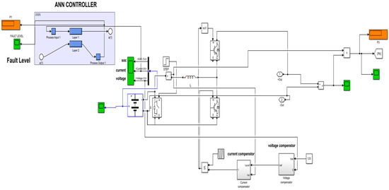
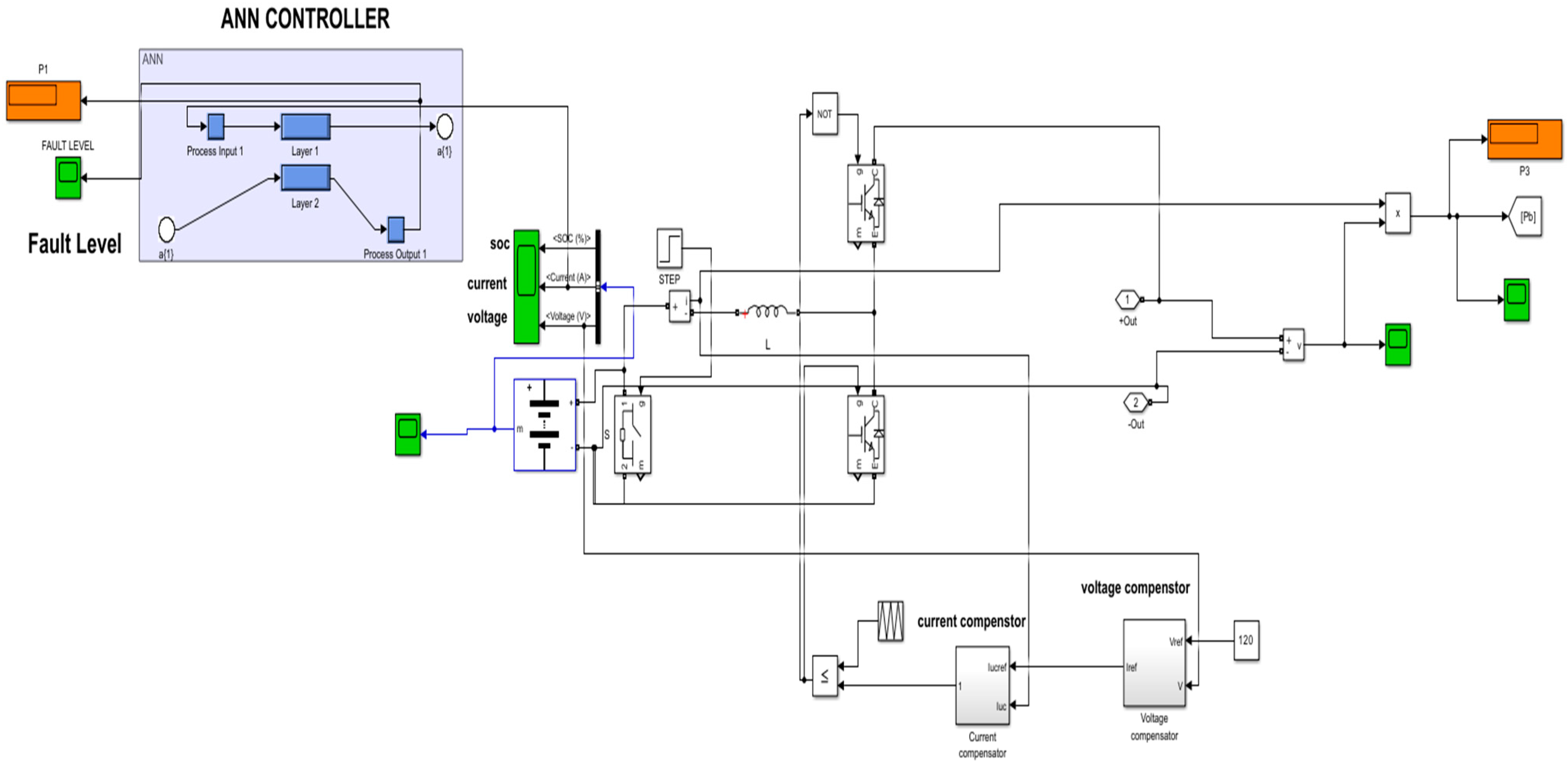
Figure 21 represents the Simulink model of the ANN controller for fault detection integrated with a bidirectional converter to provide control compensation. It also provides feedback regulation through voltage and current compensators.
Figure 21.
Simulation circuit of fault detection using an ANN controller.
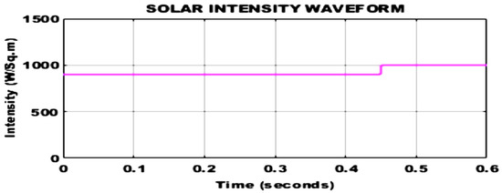
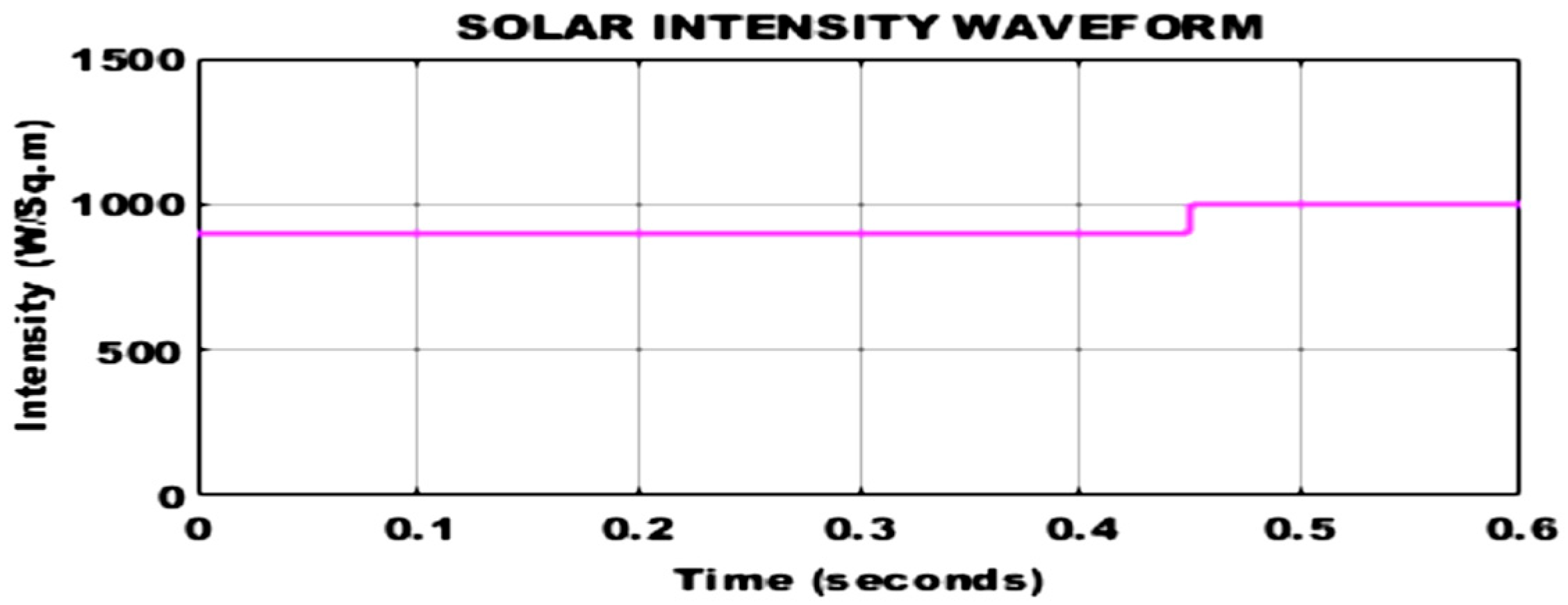
Figure 22 shows the solar PV irradiance waveform, which remains constant at 900 W/m2 and increases to 1000 W/m2 after 0.45 s, respectively.
Figure 22.
Solar PV irradiance waveform.
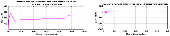
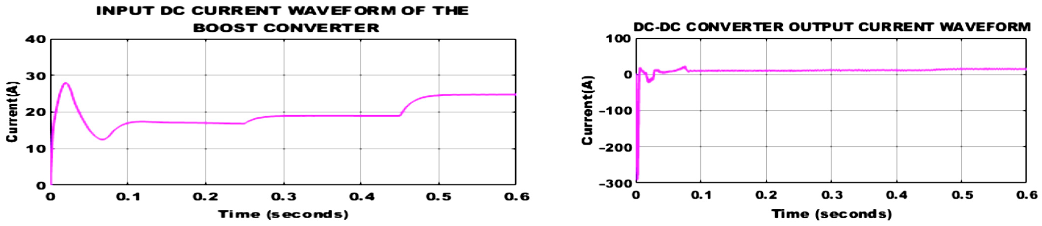
In Figure 23, the input current of the boost converter is measured at 27 A and decreases to 12 A at each step input. After 0.45 s, the source current again remains constant at 27 A. However, load current remains constant at 10 A, respectively.
Figure 23.
Simulation result of boost converter’s source and load current.
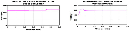
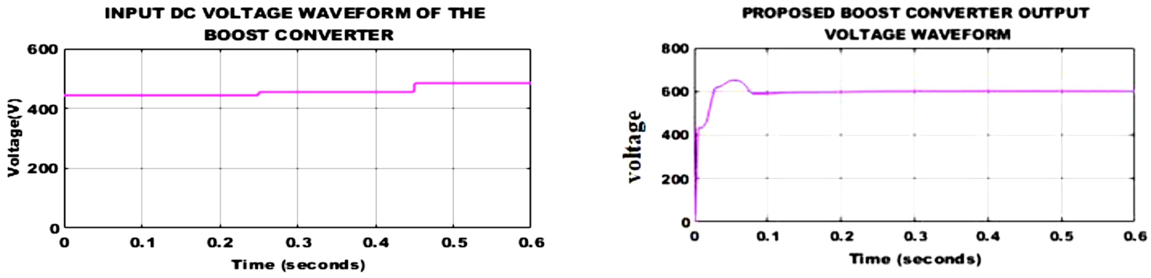
The boost converter’s source and load voltage waveforms are displayed in Figure 24. Here, the system measures the input voltage at 440 V DC, and after 0.25 s, it slightly reaches 450 V and then 500 V with respect to each step change. However, the load voltage maintains at constant 600 V DC, respectively.
Figure 24.
Simulation result of boost converter’s input and load voltage.
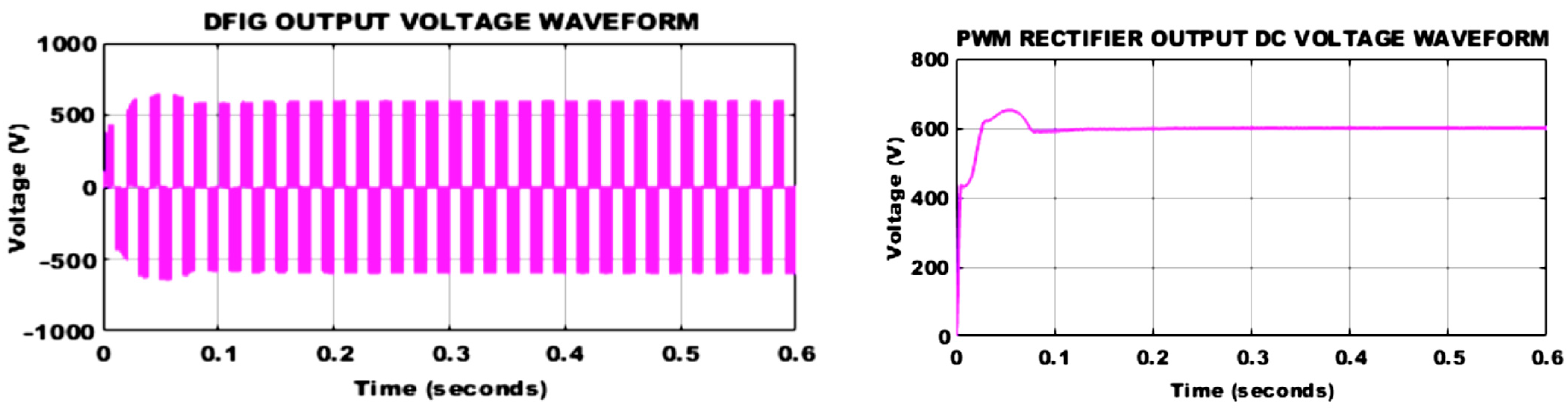
The waveform of the wind source AC output lies in the range between 500 V and −500 V range and its corresponding PWM rectified DC output of 600 V reaches steady state at 0.1 s, as presented in Figure 25.
Figure 25.
Output voltage waveforms of the DFIG and PWM rectifier.
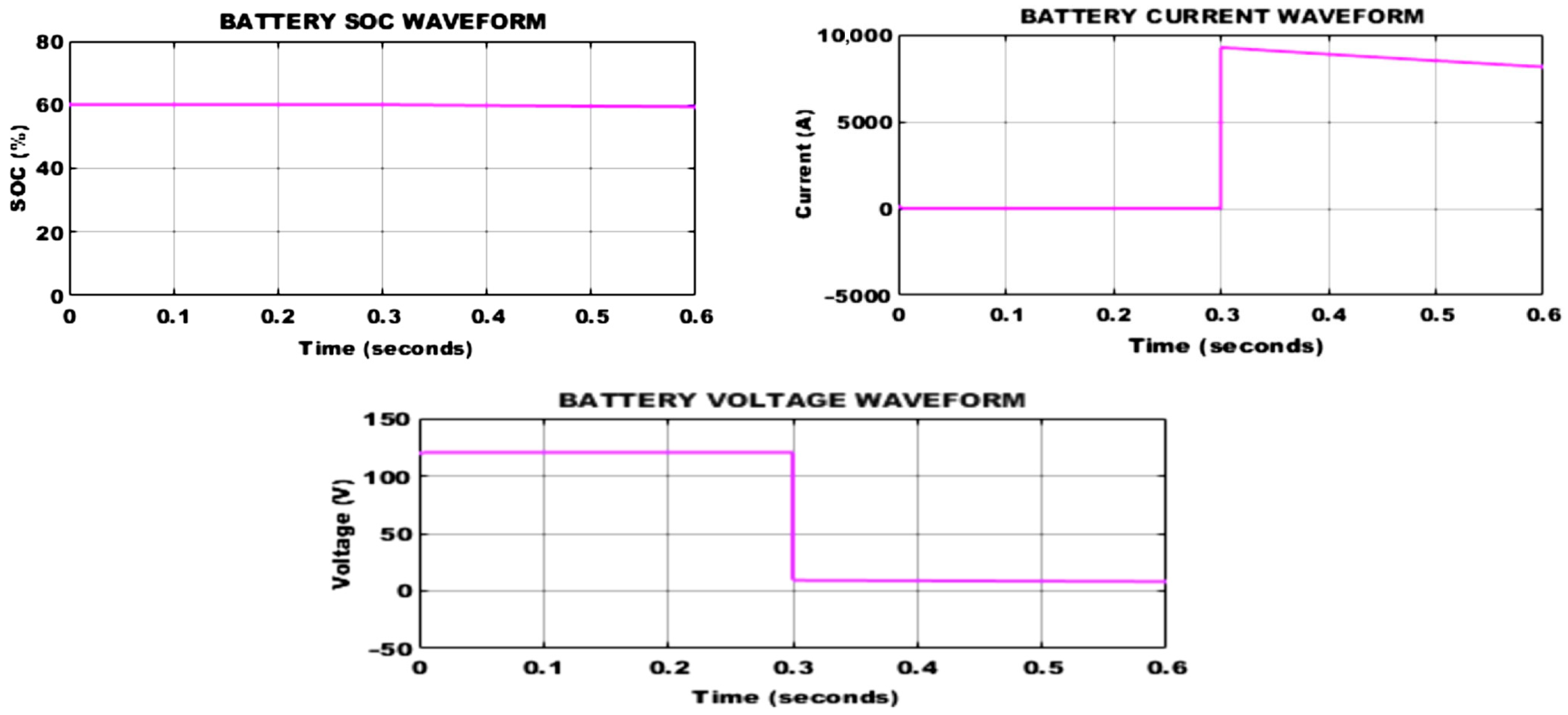
The corresponding battery characteristics are shown in Figure 26. It shows that the SOC remains stable at 60% between 0 and 0.6 s, where the voltage decreases at 0.3 s and remains constant at 10 V, respectively.
Figure 26.
Battery characteristics.
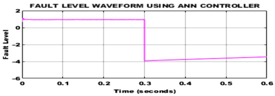
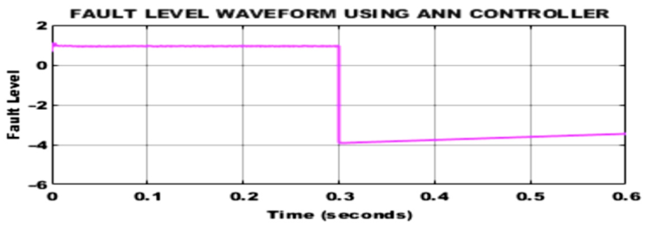
Figure 27 represents the fault level waveform using an ANN controller, where the fault level decreases rapidly at 0.3 s and then slightly increases. The time taken during the fault injection is approximately 0.30 s, and the ANN controller output deviation occurs at 0.305 s.
Figure 27.
Simulink of fault detection using an ANN controller.
Therefore, the response time and true positive rate (TPR) can be calculated as,
Here, is the number of detected fault events, and is the number of faults not detected by the ANN controller.
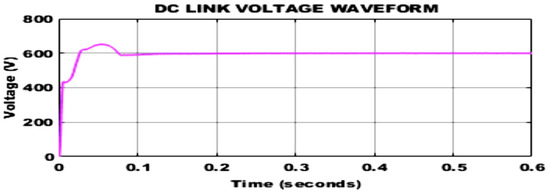
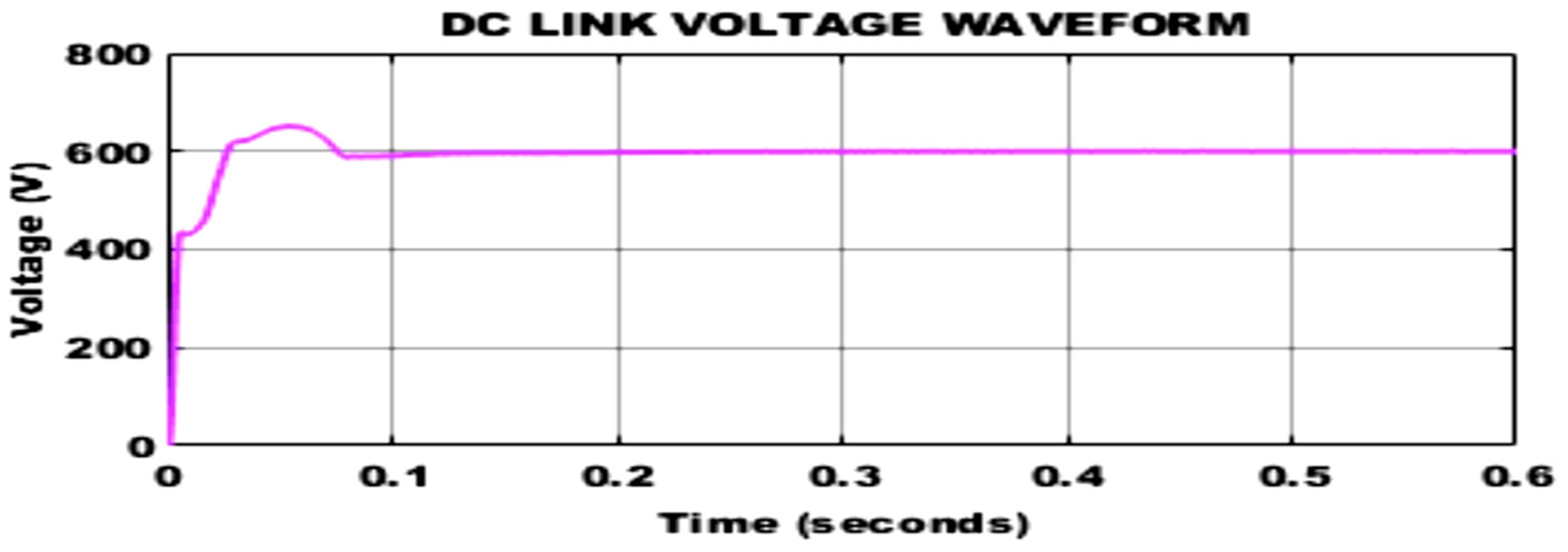
Finally, the system DC link voltage is achieved at 600 V and remains constant after 0.1 s, as shown in Figure 28.
Figure 28.
DC link voltage waveform.
4.3. EMS Performance Under Dynamic Response Conditions
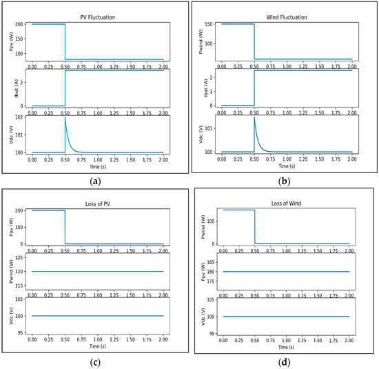
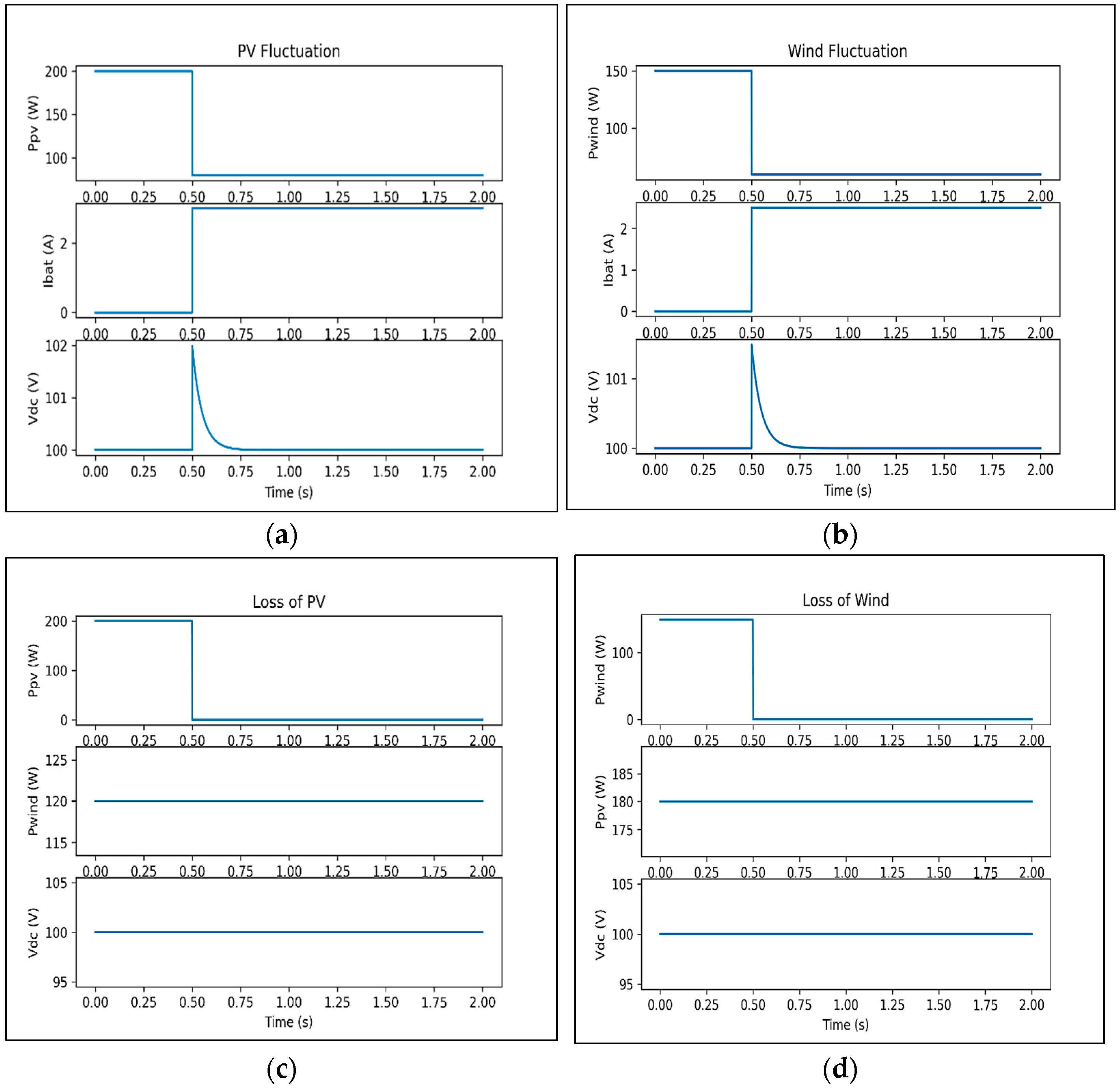
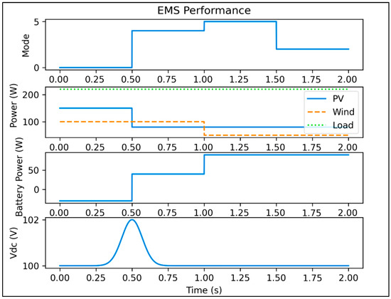
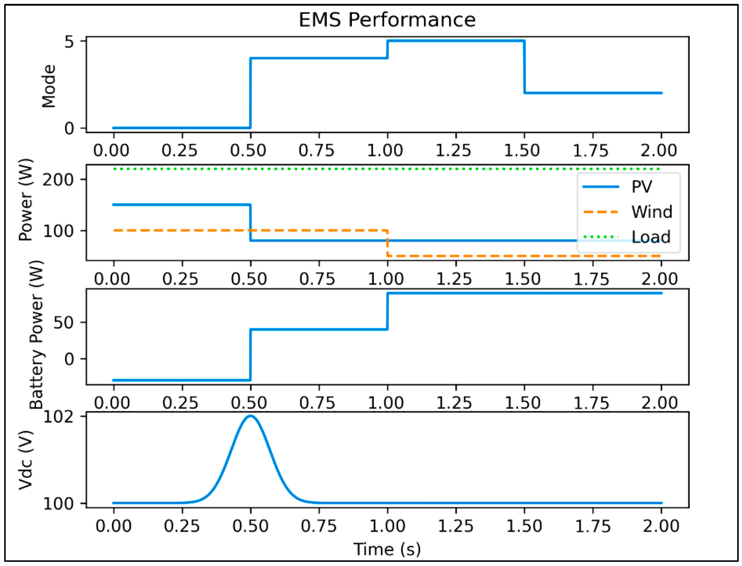
To evaluate the robustness of the proposed energy management system (EMS), dynamic simulations are performed to illustrate its decision-making capability under various operating conditions, including PV and wind fluctuations and source disconnection. The results demonstrate that the battery effectively compensates for the power deficit, ensuring uninterrupted load supply and maintaining a stable DC bus voltage. In all cases, the DC bus voltage remains stable with minimal deviation, confirming the effectiveness of the proposed EMS and ANN-based control strategy. During the PV fluctuation shown in Figure 29a, a sudden reduction in PV power at t = 0.5 s is compensated by the battery, maintaining a stable DC voltage. During the wind fluctuation shown in Figure 29b, a sudden reduction in wind power at t = 0.5 s effectively compensates and maintains a stable DC voltage. Under the PV source disconnection at t = 0.5 s, shown in Figure 29c, the wind and battery maintain an uninterrupted power supply and DC bus stability. Under the wind source disconnection at t = 0.5 s shown in Figure 29d, the PV and battery maintain continued operation and DC bus stability. Hence, the DC bus voltage remains regulated throughout, confirming the effectiveness of the EMS strategy. The EMS dynamically transitions between operating modes and regulates power distribution among PV, wind, and battery sources by maintaining a stable DC voltage. The overall performance of the proposed EMS under dynamic operating conditions is shown in Figure 30. This mode transition plot further confirms the real-time decision-making capability of the EMS.
Figure 29.
Scenarios of dynamic response of the proposed system: (a) PV power fluctuation, (b) wind power fluctuation, (c) PV Loss, (d) wind Loss.
Figure 30.
EMS performance waveform.
4.4. Stability Analysis
The stability of the proposed system is analyzed based on the DC bus voltage dynamics. The system can be represented as a first-order non-linear mode, where the DC bus capacitor governs the voltage dynamics. A Lyapunov function was defined in terms of voltage error, and the control law is designed to ensure that the Lyapunov function derivative is negative infinite. This simplifies that the system is globally asymptotically stable. Furthermore, the ANN is used for only fault detection and mode selection, so it does not directly affect the system dynamics, ensuring overall stability. Therefore, the closed-loop stability is primarily governed by the converter control law. The simulation results further validate the stable operation under various disturbances.
The objective of the controller is to regulate the DC bus voltage Vdc to a reference value V*dc. The dynamics of the DC bus voltage can be determined by the following Equation (13),
Hence, error can be represented as
Where Lyapunov function and stability condition
While substituting dynamics,
By designing the control input,
Since , the system is globally asymptotically stable.
4.5. Power Loss Analysis and Efficiency Calculation
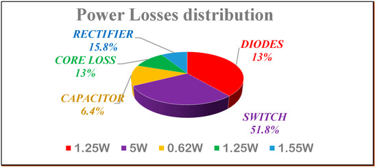
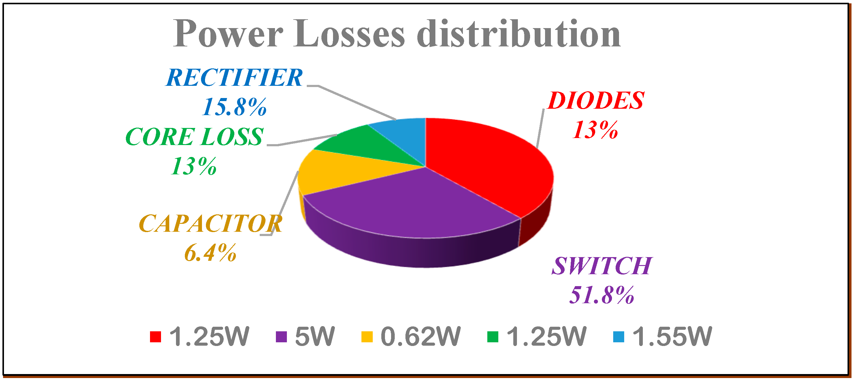
Power loss analysis plays a substantial role in the converter efficiency calculation. The loss distribution of the proposed system is displayed in Figure 31. The switching and conduction loss will occur during the switch or diode ‘On’ position, and it can be expressed as follows:
Figure 31.
Power losses distribution.
The MOSFET switch losses depend on,
MOSFET’s total losses are calculated as .
The following expression calculates the diode power loss,
The total diode losses are calculated as .
Also, the capacitor ESR power loss and inductor copper losses are expressed as,
In addition, the rectifier losses can be estimated as,
Hence, the total converter power loss is obtained as,
Hence, the converter efficiency can be calculated as,
This demonstrates that the proposed converter achieves high efficiency under the rated operating condition. The calculated losses are consistent with the device parameters and laboratory prototype, thereby justifying the efficiency calculation.
A quantitative performance of the ANN controller with other existing controllers is presented in Table 8. The overall performance comparison of the proposed converter with the state-of-the-art converters is presented in Table 9. The comparison is made based on the number of components, gain, switching frequency, and efficiency.
Table 8.
Quantitative analysis of the proposed ANN controller.
Table 9.
Performance comparison with the state-of-the-art of the converters.
4.6. Thermal Analysis and EMI Suppression
The thermal performance of the proposed system can be evaluated under maximum power operating conditions. The heat sink temperature is measured by using a temperature sensor, and the junction temperature is estimated by using thermal resistance models.
Under maximum power (200 W), the estimated junction temperature can be written as,
Here, total thermal resistance = , ,
Therefore, junction temperature
Similarly, total thermal resistance =
Junction temperature .
Thus, the results show that the junction temperature of the MOSFET and the diode remains well within the safe operating limits. Under full-load conditions, the estimated junction temperature is approximately and , which is significantly lower than the maximum rated temperature of the device. The results confirm that all the power components operate within safe thermal limits, ensuring thermal operation. To mitigate EMI at the 50 kHz switching frequency, several suppression techniques are incorporated in the hardware design. Proper PCB layout, including effective grounding and short loop paths, is used to minimize high-frequency noise. Gate resistors are used to control the switching speed and reduce dv/dt. LC filters are used at the input/output stages to suppress noise. These measures ensure stable operation and compliance with EMI requirements.
5. Experimental Results
5.1. Experimental Setup
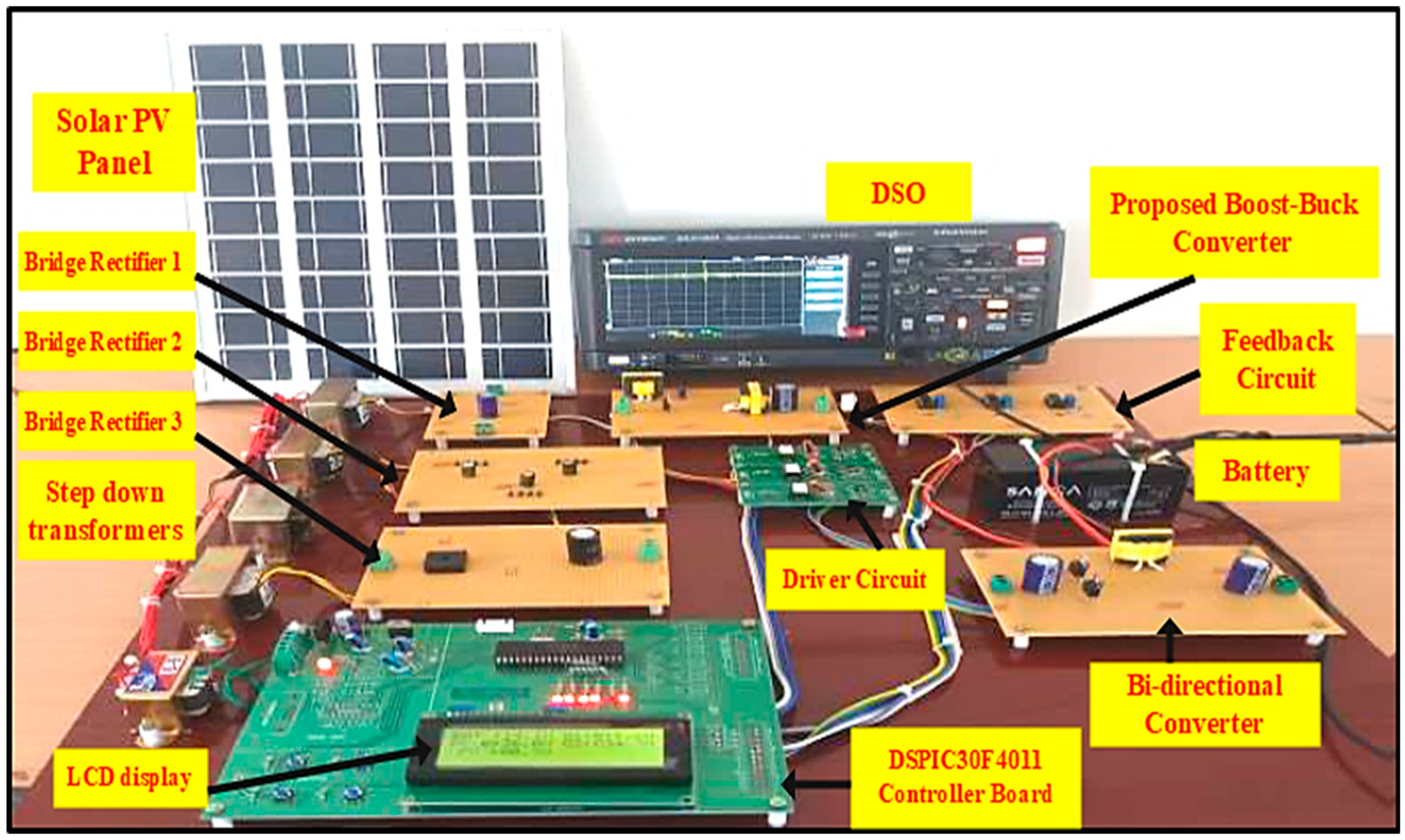
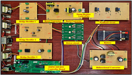
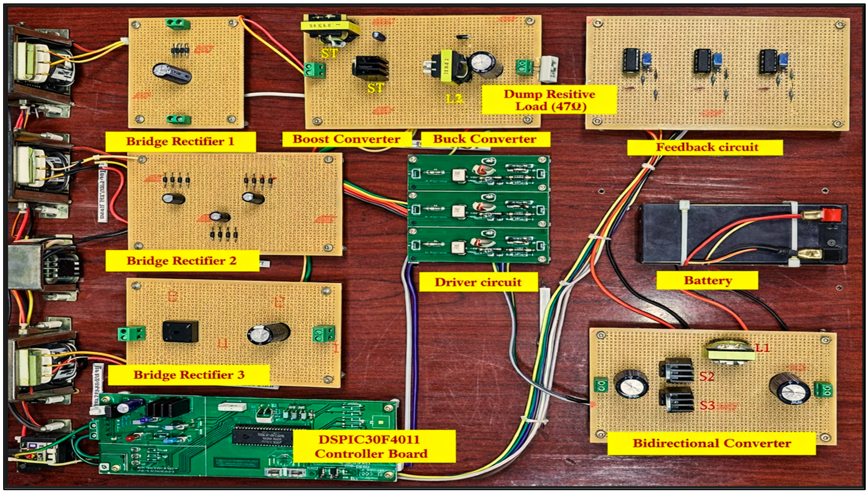
A scaled-down version of a 200 W experimental setup has been developed and built in the laboratory, directly scalable to the 1 kW system as shown in Figure 32, to verify and validate the effectiveness and converter performance using low-power operating sources. The hardware specifications are presented in Table 10.
Figure 32.
Experimental setup.
Table 10.
Hardware components and their specifications.
The solar PV source is integrated with the boost–buck-derived converter configuration to power the common DC bus. Bridge rectifier-1 is incorporated to convert the AC power to DC power, due to the non-availability of PV power. Bridge rectifier-2 is used for the conversion of AC to DC to amplify and power the driver circuits. Bridge rectifier-3 is incorporated for the wind source converting AC to DC power, integrated with the boost–buck configuration to power the DC bus. A 4-channel digital storage oscilloscope (DSO) is used to capture the results, while LCDs show the real-time data effectively. The overall configuration demonstrates the integration of solar PV energy and wind energy conversion, power management, and monitoring for effective energy utilization. At the source side, the PV system produces the nominal DC voltage ranging from 30 V to 40 V, corresponding to 150 W, while the wind source, implemented with the BR101 Rectron-bridge rectifier, is limited to 150 W to ensure safe operation under laboratory conditions. The maximum load power is approximately 200 W, aligning with the combined generation capacity and storage limits. This harmonized converter topology can prevent sustained DC bus overvoltage, reduce battery stress, and ensure reliable operation across all modes. The hardware prototype is shown in Figure 33. The DSPIC30F4011 microcontroller controls the switching periods of MOSFET power devices. The optimized weights and trained data are loaded into the DSPIC30F4011 microcontroller. The control algorithm is then converted into C code, compiled, and embedded onto the chip. The controller utilizes an embedded artificial neural network (ANN) to process real-time data and generate appropriate control outputs. This modulation technique controls the gate signals of MOSFETs in the boost–buck and bidirectional configurations, which enables precise voltage boosting.
Figure 33.
Hardware prototype.
During experimental validation, the following parameters are controlled and monitored to ensure repeatability and reliability. The nominal value of irradiance is measured at 1000 W/m2, with an allowable variation of 2%. The ambient temperature should be maintained at 25 °C with an allowable variation of 2 °C, and the PV module temperature should be maintained at 25 °C. The load type preferred in this proposed converter is a dump resistive load, with a variation from 1 kΩ to 47 kΩ, lasting from 0.3 s to 0.6 s. The semiconductor devices and the passive components are selected with recommended safety margins to ensure reliable operation under transient and faulty conditions. The voltage and current ratings are selected 1.3 to 1.5 times higher than the maximum calculated stress, while the thermal limits are maintained below 80% of the device-rated junction temperature.
Additionally, it incorporates dead-time insertion to prevent shoot-through in the switching devices. A control signal computed from the MPPT technique is then sent to the TLP250 drive circuit, which activates its internal LED. This LED emits light, which is detected by the photo detector within the TLP250. Upon detection, the output transistor is triggered, allowing a high current to flow to the gate of the power device. This energizes the MOSFET (S1), which enables it to switch on and off rapidly to adjust the boost converter operation.
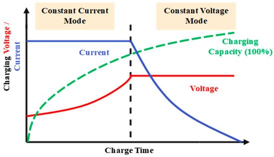
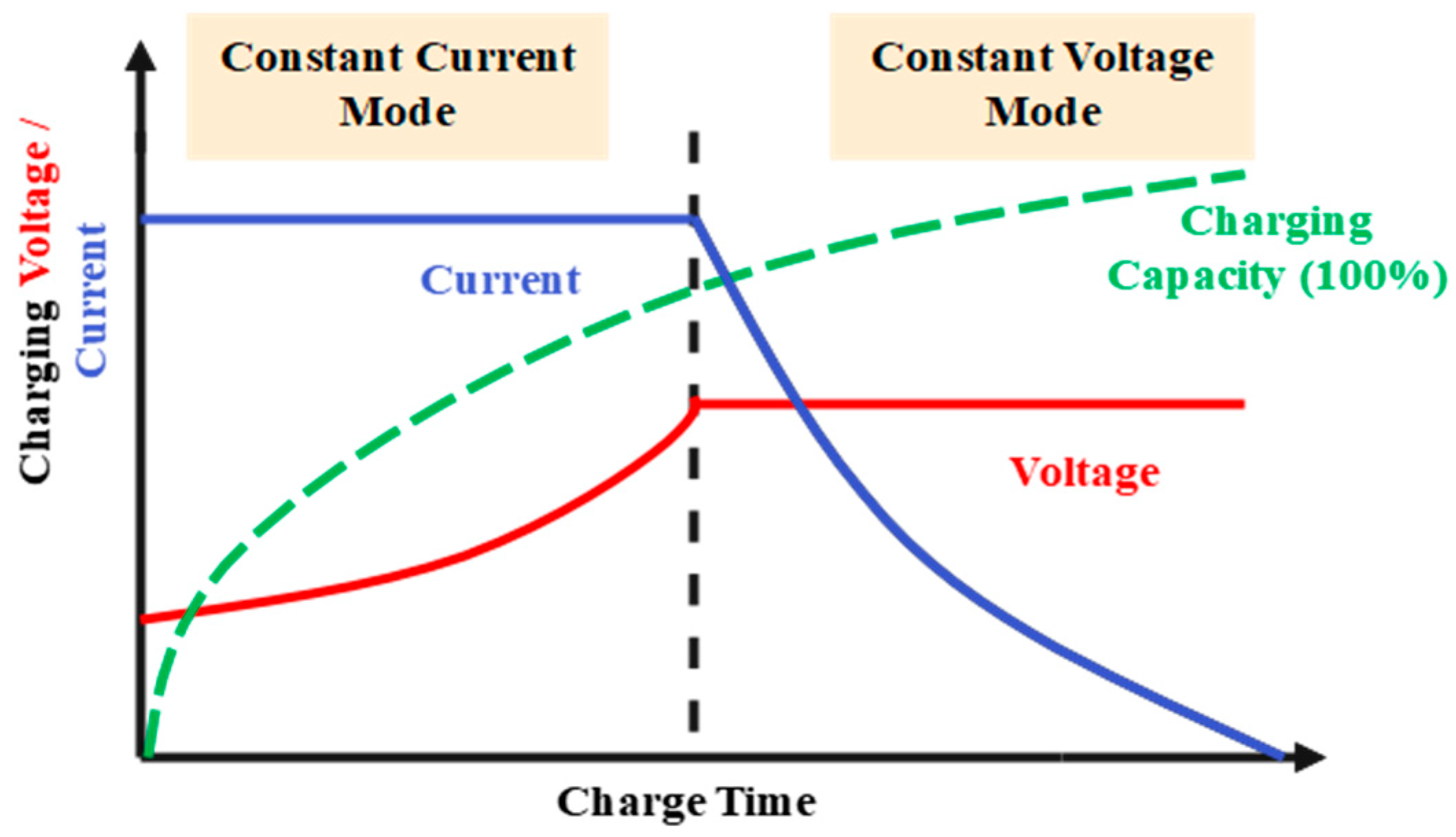
In the experimental setup, the battery is used as a load, and its charging profile shown in Figure 34 follows a standard constant-current–constant-voltage (CC-CV) charging strategy. A constant charging current is applied until the battery voltage reaches the cutoff value (VCV), in which the battery voltage is held constant, and the charging current gradually decreases. Here, the battery can be modelled as a variable resistive load, and its equivalent resistance under nominal operating conditions can be expressed as,
Figure 34.
Charging CC-CV profile of a battery.
During the constant current (CC) phase, the current is held constant at 1.5 A, while the battery voltage rises approximately from 12 V up to the cutoff voltage of 14.4 V. So, the equivalent resistance value ranges from 24 Ω to 96 Ω, respectively. During the constant voltage (CV) phase, the voltage is kept constant at 14.4 V, while the charging current decreases below 0.05 A, which tends to increase the equivalent resistance to 288 Ω. Therefore, the battery is modelled as a dynamic load during the charging process.
5.2. Experimental Results and Discussion
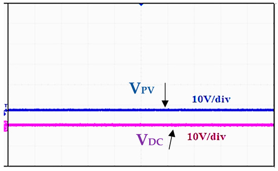
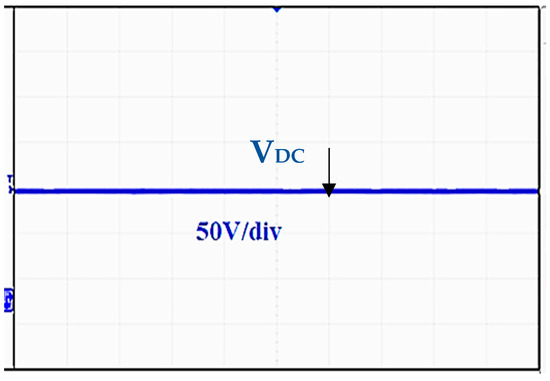
The experimental results are recorded using a four-channel Digital Storage Oscilloscope (DSO). The boost converter’s output response is shown in Figure 35. Here, the solid blue line represents a steady-state PV input voltage of 34 V, measured at 10 V/div, while the pink line indicates a DC bus voltage of approximately 36.10 V, measured at 10 V/div. During the load variation from 1 k to 47 k, the system consistently maintains a steady voltage of 36.10 V at 50 V/div, achieving efficiency of about 75% and remains stable, as shown in Figure 36.
Figure 35.
Boost converter output voltage and DC bus load voltage waveform.
Figure 36.
Experimental waveform of DC bus voltage.
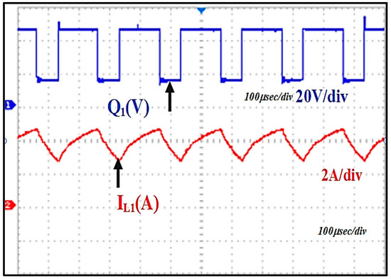
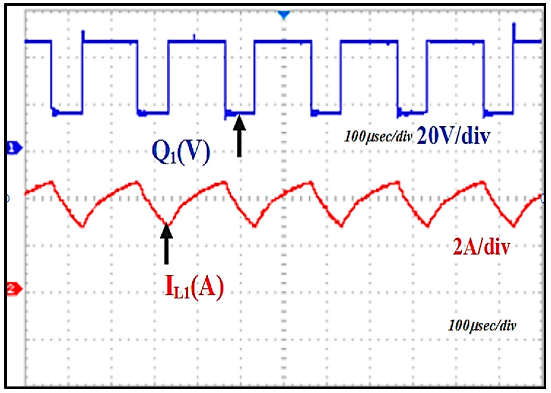
The boost converter’s switching pulse ‘Q1’ waveform and the L1 current waveform are shown in Figure 37. DSO displays a solid blue switching pulse waveform with a duty cycle of 60%. The time period indicates that the signal changes over time in a periodic pattern. The inductor current measures at 2 A, respectively.
Figure 37.
Waveform of switching pulse generation ‘Q1’ and inductor (L1) current.
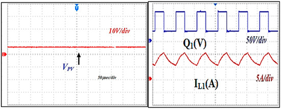
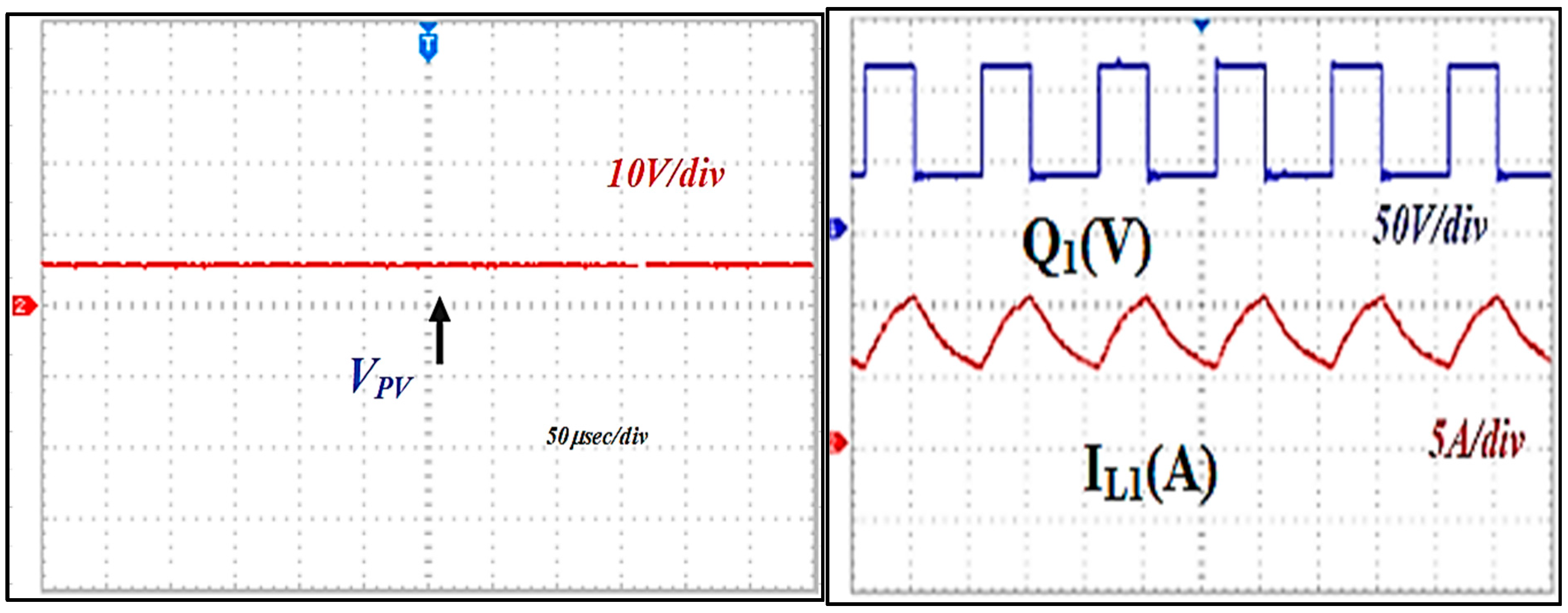
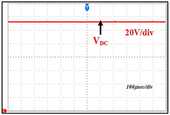
The converter is measured for variation in duty cycle from 60% to 40% with a PV input voltage of VPV = 34 V, measured at 10 V/div. The switching pulse ‘Q1’ waveform at 50 V/div and L1 current waveform at 5 A/div are shown in Figure 38. The generated DC bus load voltage is shown in Figure 39, measured at 36.10 V with a 20 V/div scale, and the output power is delivered as 55 W by maintaining the efficiency of around 75% with constant voltage regulation.
Figure 38.
Waveform of generated solar PV voltage, switching pulse and current waveform.
Figure 39.
Waveform of DC bus voltage.
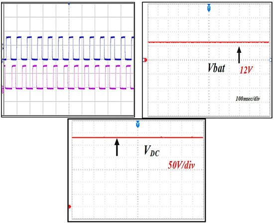
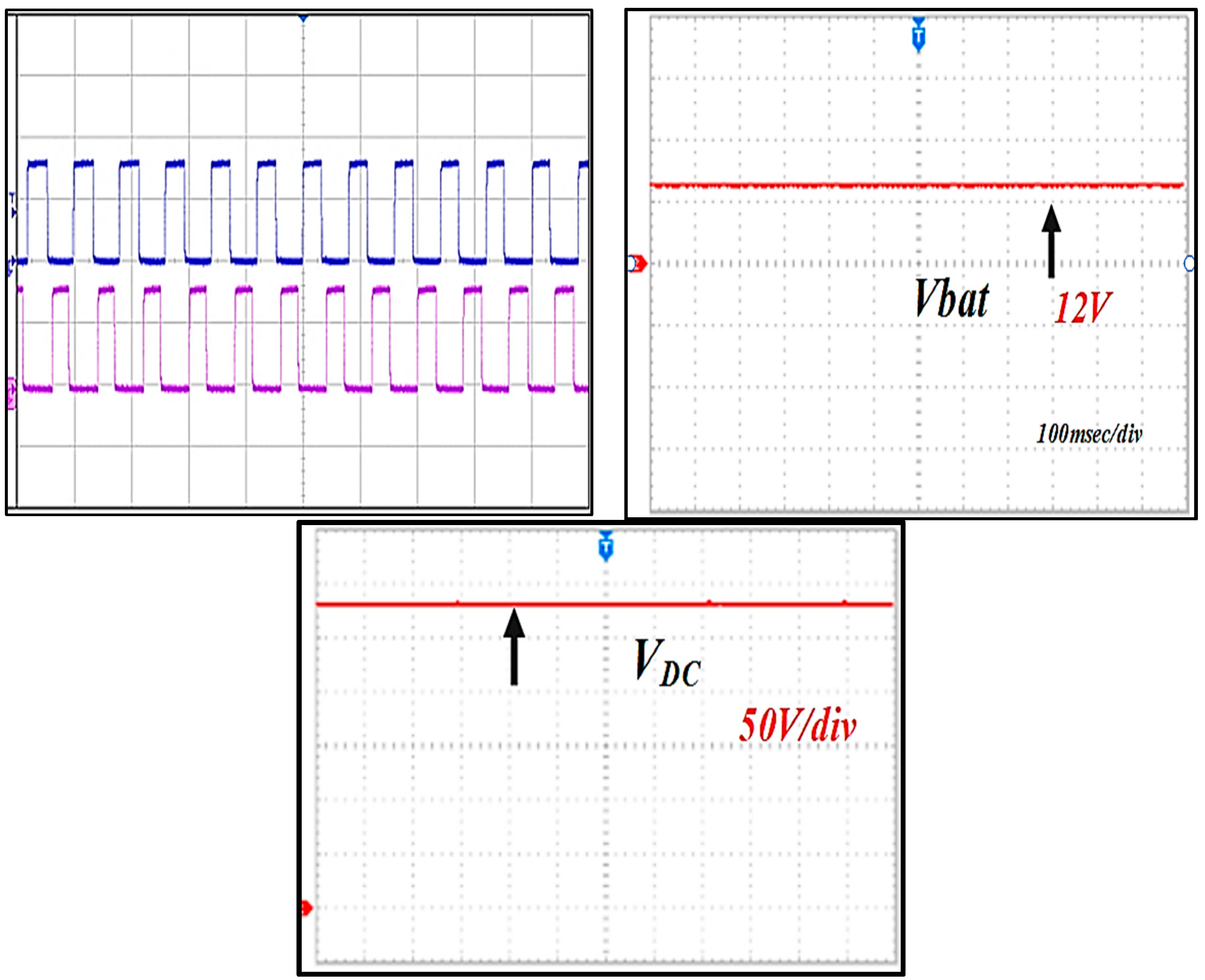
The converter’s switching pulse waveform of ‘Q2’ and ‘Q3’ in bidirectional mode is displayed in Figure 40. The solid blue and pink lines represent the switching pulses over the period of time. The blue line indicates the duty cycle ranges at 50% of ‘Q2’, whereas the pink line indicates the duty cycle ranges at 50% of ‘Q3’, respectively. The battery voltage is measured at 12 V, and the DC bus voltage is measured at 36.10 V, respectively.
Figure 40.
Waveform of switching pulse generation of Q2, Q3, battery voltage, and DC bus voltage.
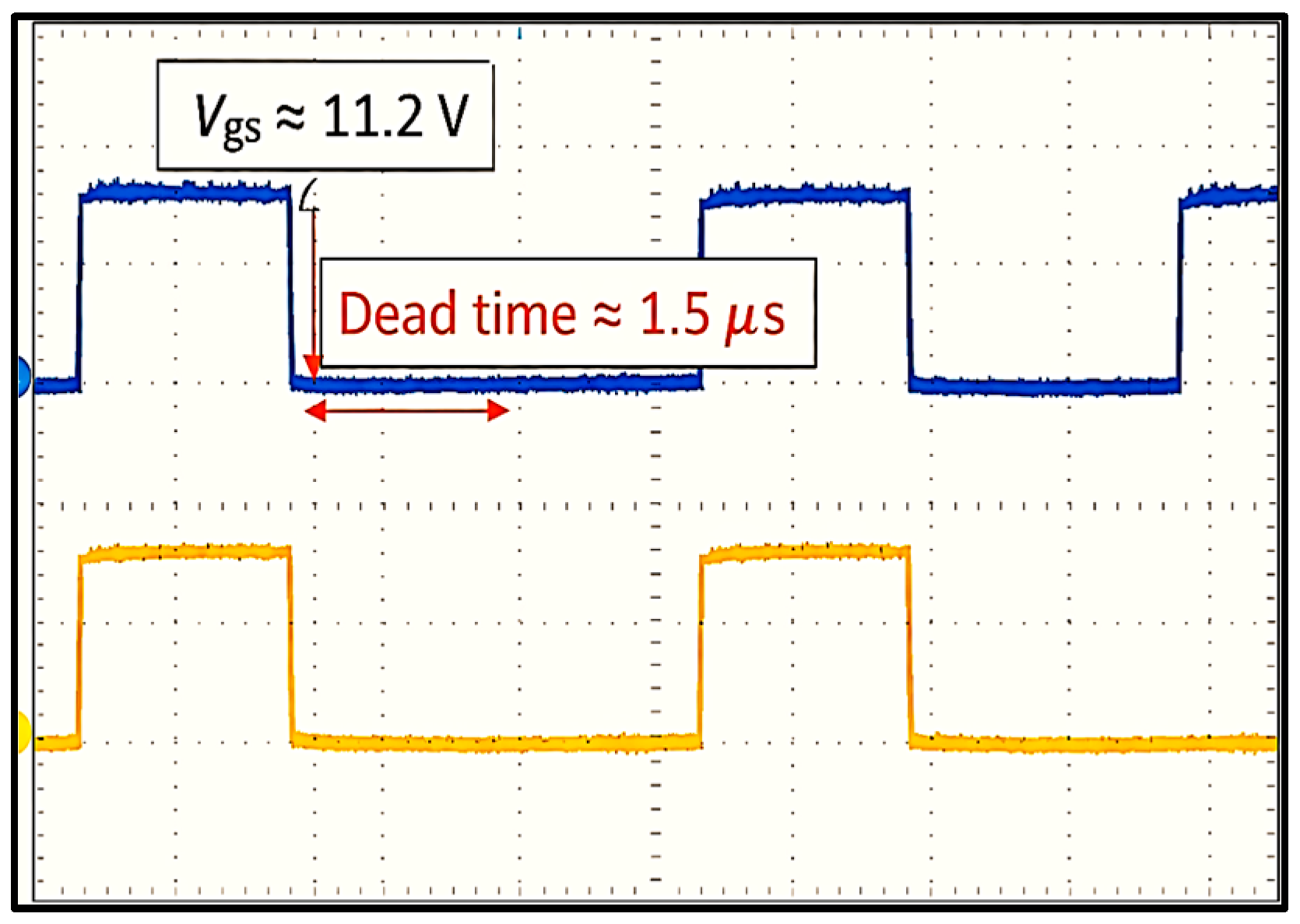
Figure 41 represents the measured gate driving signals, showing gate-to-source voltage (Vgs) and the implemented dead time between the switching pulses. The gate-to-source voltage (Vgs) of the MOSFET is observed to be approximately 11.2 V, and a dead time of approximately 1.5 µs is introduced to improve converter reliability and prevent cross-conduction. The observed experimental waveforms ensure the safe operation of the switching devices and validate their effectiveness.
Figure 41.
Experimental waveform of measured gate voltage and dead time.
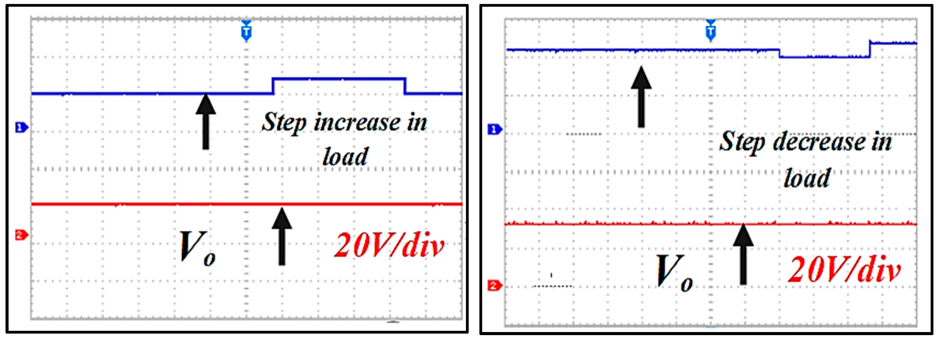
To validate the transient conditions of the system, the converter is measured at variations in load changes from 1 k to 47 k at 20 V/div, as shown in Figure 42. The converter consistently maintains better voltage regulation at the load side, improved stability under dynamic response conditions, and achieves an efficiency of nearly 75%, respectively.
Figure 42.
Dynamic response conditions of the system.
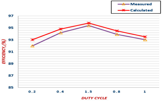
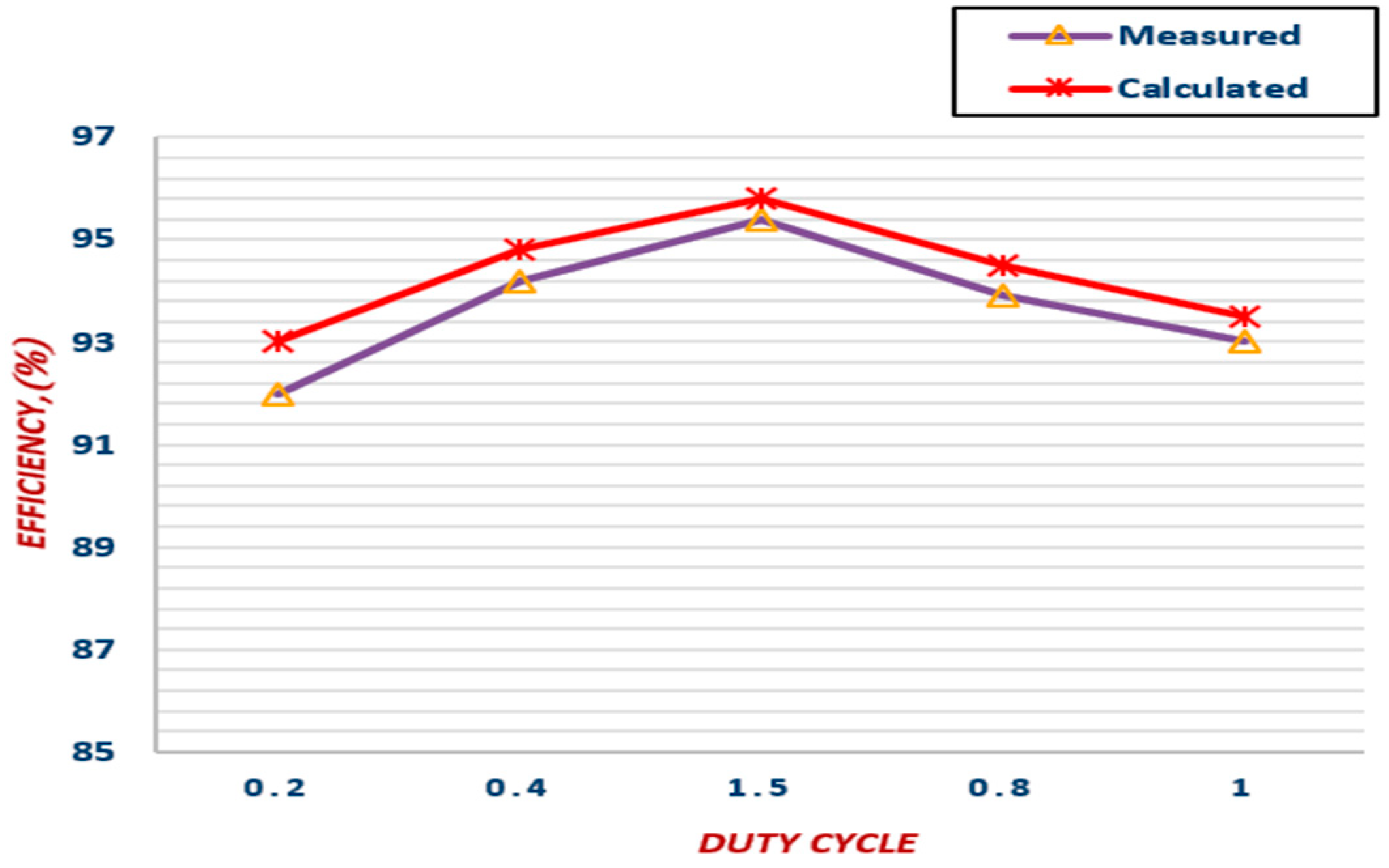
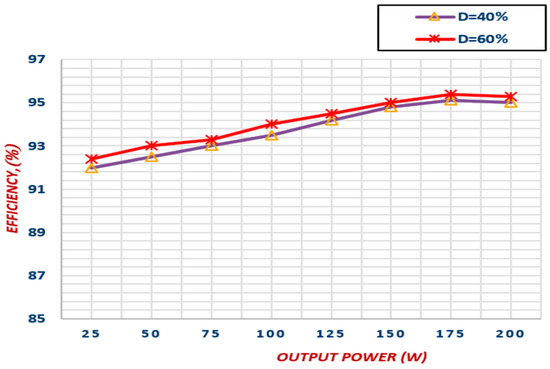
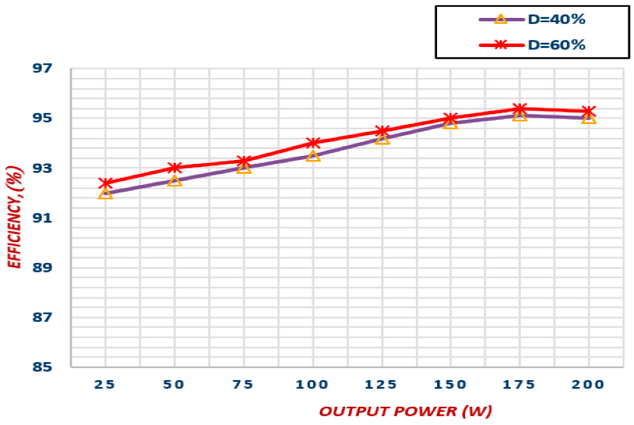
To verify the correctness of the efficiency, the theoretical and experimental results are plotted and compared at various duty cycle ranges shown in Figure 43. It is evident that the experimental results strongly agree with the theoretical values. Moreover, Figure 44 compares the measured efficiency at various power ranges during variation of duty cycle from 40% to 60%, respectively. The simulation and experimental findings of the proposed system are discussed in Table 11, together with the parameter interpretation and similarities.
Figure 43.
Calculated and measured efficiency comparisons.
Figure 44.
Measured efficiency and output power comparisons during variation in duty cycle.
Table 11.
Performance observations of the proposed configuration.
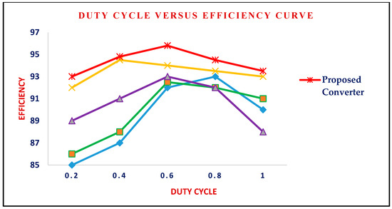
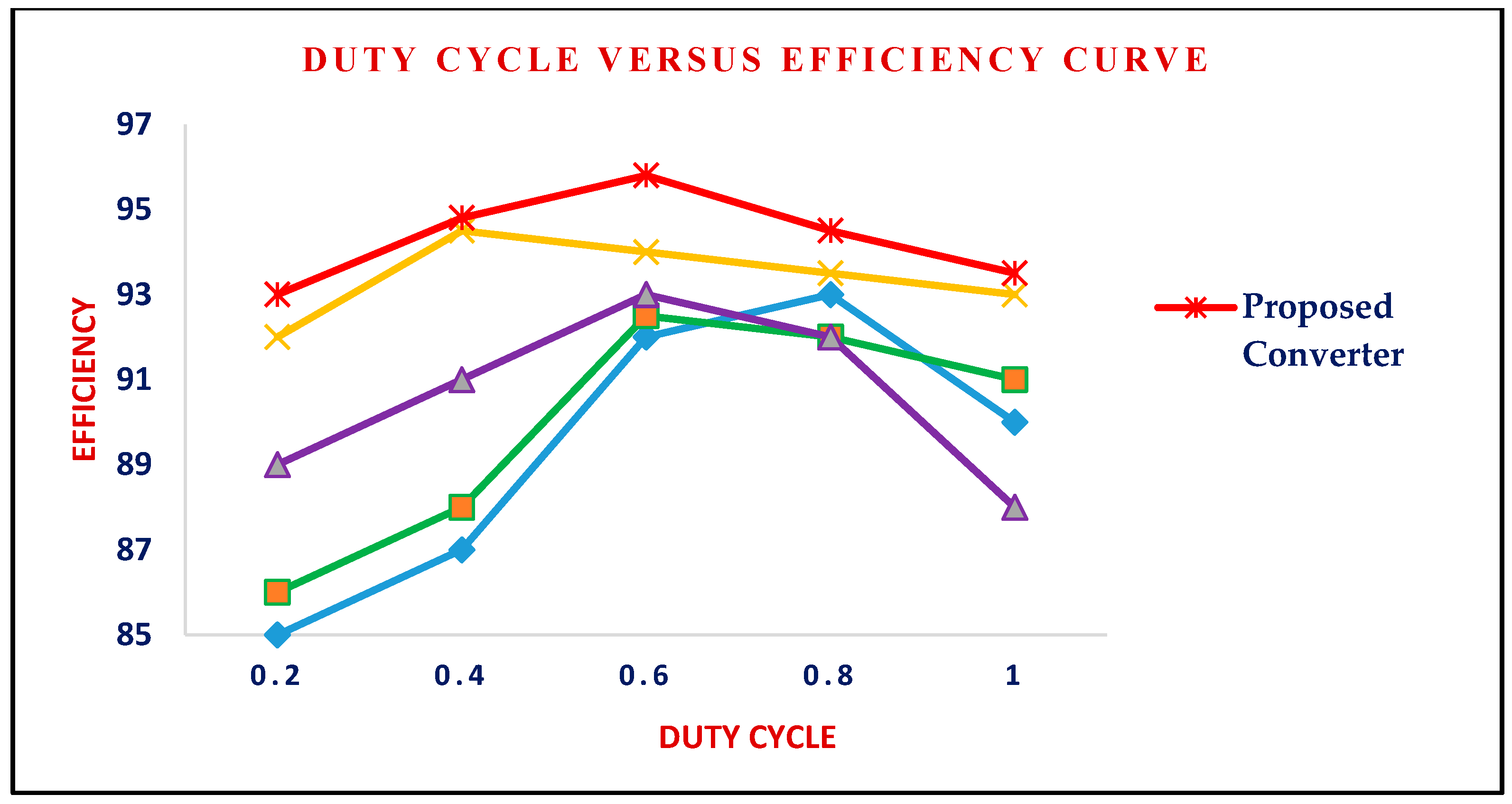
Finally, the overall performance curve of the proposed system is presented in Figure 45 for various duty-cycle ranges with respect to efficiency. Here, the blue solid line [8] gradually increases to 93% efficiency around 0.6 to 0.8 duty cycle but less efficient at low and high duty cycles, the green solid line [26] steadily increases to 93% shows moderate performance, the purple solid line [29] peaks around 93% efficiency, but performance degrades significantly at high duty cycle range, and the yellow solid line [31] consistently shows high efficiency but slightly lower than the proposed topology. Hence, it is proven that the red solid line represents the proposed system, showing superior and stable performance compared with other existing configurations. Therefore, the proposed method maintains the highest efficiency at all duty cycles, demonstrating its effectiveness and reliability.
Figure 45.
Performance curve of the proposed system.
6. Discussions
The proposed smart energy management strategy, which incorporates grid, storage, and dump resistive load, can provide a promising solution for maximizing renewable energy utilization, coordinated control, and enhanced converter efficiency, which increases the stability of the DC bus voltage and cost balance, and also ensures the performance of the system and reliable operation under all conditions.
The proposed system lessens stress and extends the battery’s lifespan by modifying charging modes according to the battery condition. In order to reduce charging time without sacrificing safety, it dynamically adjusts voltage and current. Furthermore, it ensures safe and dependable charging in a variety of circumstances, minimizing energy loss and enhancing performance while maintaining optimal power delivery throughout the charging cycle. The use of cutting-edge deep learning techniques for more accurate fault detection and predictive control in EV batteries is part of the research’s future scope. The system’s efficiency can be further improved by increasing its compatibility with various renewable energy sources. The proposed ANN-based controller can be extended through integration with IoT and cloud-based monitoring platforms to overcome the limitations of remote fault diagnosis, scalable monitoring of multiple converters, and adaptive ANN retraining using long-term operational data. This will enhance the system scalability, support predictive maintenance, and improve reliability in large-scale PV and microgrid applications.
7. Conclusions
A new multi-source DC-DC converter-based smart energy management system utilizing solar PV and wind sources for electric vehicle applications is introduced in this article. To promote efficient battery charging, discharging, and enhanced protection from faults, an artificial neural network (ANN) approach is incorporated. The key advantages of the proposed work over the existing configurations are as follows:
- Hybridization of multiple sources can satisfy the needs of load demand. To maintain power balance and system stability in islanded DC microgrids, dump loads are utilized.
- It increases efficiency up to 95.4%, lowers voltage regulation error to less than 1%, and incorporates an ANN approach, which allows real-time monitoring, intervention, and estimation of faults within 15 ms.
- The suggested converter significantly performs under dynamic response scenarios and promotes improved stability.
- Without using any additional sensors and high-frequency isolation transformers, this system provides seamless mode transition (charge–discharge) and improved transient response, which results in better voltage regulation and higher efficiency.
The main contributions of the proposed work are summarized as follows:
- A multi-input ANN-based fault detection framework is developed for a hybrid power system utilizing multiple renewable sources to identify system conditions.
- A real-time implementation strategy is proposed by incorporating threshold-based decision logic to enhance fault detection capability and reduce false alarms.
- A detailed stress, loss, and thermal analysis of key components is performed, and the results are validated through waveform analysis under different operating modes.
- A comprehensive fault taxonomy is implemented, including overvoltage, undervoltage, overcurrent, sensor faults, and internal short-circuit conditions, enabling stable and robust operation.
The performance and effectiveness of the proposed system are evaluated and verified through the MATLAB simulation and experimental 200 W prototype validation, demonstrating fast convergence, high accuracy, and reliability under varying conditions.
Author Contributions
Conceptualization, N.K.M.; methodology, G.H.; software, V.H.; validation, N.K.M. and S.N.K.; formal analysis, G.H. and V.H.; investigation, N.K.M.; resources, S.N.K.; data curation, N.K.M.; writing—V.R.; writing—review and editing, V.R.; visualization, V.R.; supervision, N.K.M.; project administration, S.N.K. All authors have read and agreed to the published version of the manuscript.
Funding
This research received no external funding.
Data Availability Statement
The original contributions presented in this study are included in the article. Further inquiries can be directed to the corresponding author.
Acknowledgments
The authors have reviewed and edited the output and take full responsibility for the content of this publication.
Conflicts of Interest
Author S. Nanda Kumar was employed by the company Power Grid Corporation of India. The remaining authors declare that the research was conducted in the absence of any commercial or financial relationships that could be construed as a potential conflict of interest. The company had no role in the design of the study; in the collection, analyses, or interpretation of data; in the writing of the manuscript, or in the decision to publish the results.
Abbreviations
The following abbreviations are used in this manuscript:
| EV | Electric Vehicle |
| WECS | Wind Energy Conversion System |
| ANN | Artificial Neural Network |
| EMS | Energy Management System |
| PWM | Pulse Width Modulation |
| PV | Photovoltaic |
| SOC | State of Charging |
| LED | Light Emitting Diode |
| VMC | Voltage Multiplier Cell |
| MPPT | Maximum Power Point tracker |
| EMI | Electromagnetic Interference |
| PID | Proportional-Integral-Derivative |
References
- Sayed, K.; Almutairi, A.; Albagami, N.; Alrumayh, O.; Abo-Khalil, A.G.; Saleeb, H. A Review of DC-AC Converters for Electric Vehicle Applications. Energies 2022, 15, 1241. [Google Scholar] [CrossRef] [Scilit]
- Kim, I.; Park, J.W. Multifunctional Integrated DC–DC Converter for Electric Vehicles. IEEE Trans. Power Electron. 2024, 39, 7252–7263. [Google Scholar] [CrossRef] [Scilit]
- Litrán, S.P.; Durán, E.; Semião, J.; Díaz-Martín, C. Multiple-Output DC–DC Converters: Applications and Solutions. Electronics 2022, 11, 1258. [Google Scholar] [CrossRef] [Scilit]
- Krishna, B.; Lithesh, G.; Karthikeyan, V. A novel high-gain bidirectional DC–DC converter for EV onboard charger applications. Int. J. Circ. Theor. Appl. 2022, 50, 2531–2547. [Google Scholar] [CrossRef] [Scilit]
- Martinez-Vera, E.; Banuelos-Sanchez, P. Review of Bidirectional DC-DC Converters and Trends in Control Techniques for Applications in Electric Vehicles. IEEE Lat. Am. Trans. 2024, 22, 144–155. [Google Scholar] [CrossRef] [Scilit]
- Shi, C.; Wang, S. A Study on the Device Topology and Control Strategy of a Hybrid Three-Port Photovoltaic Energy Storage Grid-Connected Converter. Electronics 2025, 14, 1966. [Google Scholar] [CrossRef] [Scilit]
- Maurya, V.P.; Singh, R.K. A Multifunction Power Converter With Multimode Capabilities for Low Power Electric Vehicles. IEEE Trans. Power Electron. 2025, 40, 13778–13791. [Google Scholar] [CrossRef] [Scilit]
- Tekgun, B.; Tekgun, D.; Alan, I. A multi-functional quasi-single stage bi-directional charger topology for electric vehicles. Ain. Shams. Eng. J. 2024, 15, 102471. [Google Scholar] [CrossRef] [Scilit]
- Dhananjaya, M.; Potnuru, D.; Manoharan, P.; Alhelou, H.H. Design and Implementation of Single-Input-Multi-Output DC-DC Converter Topology for Auxiliary Power Modules of Electric Vehicle. IEEE Access 2022, 10, 76975–76989. [Google Scholar] [CrossRef] [Scilit]
- Kim, I.; Park, J.W. New Integrated DC–DC Conversion System for Electric Vehicles. IEEE Trans. Ind. Electron. 2024, 71, 7126–7135. [Google Scholar] [CrossRef] [Scilit]
- Challoob, A.F.; Bin Rahmat, N.A.; A/L Ramachandaramurthy, V.K.; Humaidi, A.J. Energy and battery management systems for electrical vehicles: A comprehensive review & recommendations. Energy Explor. Exploit. 2023, 42, 341–372. [Google Scholar] [CrossRef] [Scilit]
- Dini, P.; Saponara, S.; Colicelli, A. Overview on Battery Charging Systems for Electric Vehicles. Electronics 2023, 12, 4295. [Google Scholar] [CrossRef] [Scilit]
- Rajeswari, V.; Mohanty, N.K. A Robust Controller for a Novel Single-Switch Non-Isolated Converter with Low-Order Ripples for Electric Vehicle Chargers. Sustainability 2024, 16, 10463. [Google Scholar] [CrossRef] [Scilit]
- Wang, Z.; Su, X.; Zeng, N.; Jiang, J. Overview of Isolated Bidirectional DC–DC Converter Topology and Switching Strategies for Electric Vehicle Applications. Energies 2024, 17, 2434. [Google Scholar] [CrossRef] [Scilit]
- Recalde, A.; Cajo, R.; Velasquez, W.; Alvarez-Alvarado, M.S. Machine Learning and Optimization in Energy Management Systems for Plug-In Hybrid Electric Vehicles: A Comprehensive Review. Energies 2024, 17, 3059. [Google Scholar] [CrossRef] [Scilit]
- Lipu, M.S.H.; Mamun, A.A.; Ansari, S.; Miah, M.S.; Hasan, K.; Meraj, S.T.; Abdolrasol, M.G.M.; Rahman, T.; Maruf, M.H.; Sarker, M.R.; et al. Battery Management, Key Technologies, Methods, Issues, and Future Trends of Electric Vehicles: A Pathway toward Achieving Sustainable Development Goals. Batteries 2022, 8, 119. [Google Scholar] [CrossRef] [Scilit]
- Kalaivani, P.; Joice, C.S. Design and modelling of a neural network-based energy management system for solar PV, fuel cell, battery and ultracapacitor-based hybrid electric vehicle. Electr. Eng. 2024, 106, 689–709. [Google Scholar] [CrossRef] [Scilit]
- Leal, W.C.; Godinho, M.O.; Bastos, R.F.; de Aguiar, C.R.; Fuzato, G.H.F.; Machado, R.Q. Cascaded Interleaved DC–DC Converter for a Bidirectional Electric Vehicle Charging Station. IEEE Trans. Ind. Electron. 2024, 71, 3708–3717. [Google Scholar] [CrossRef] [Scilit]
- Wang, T.; Zhang, J.; Li, X.; Chen, S.; Ma, J.; Han, H. The Control Strategies for Charging and Discharging of Electric Vehicles in the Vehicle–Grid Interaction Modes. World Electr. Veh. J. 2024, 15, 468. [Google Scholar] [CrossRef] [Scilit]
- Milton, C.; Sivarani, T.S. Monarch butterfly optimization based energy management system for electric vehicle with interleaved landsman converter. Automatika 2024, 66, 43–68. [Google Scholar] [CrossRef] [Scilit]
- De Melo, R.R.; Tofoli, F.L.; Daher, S.; Antunes, F.L.M. Interleaved bidirectional DC–DC converter for electric vehicle applications based on multiple energy storage devices. Electr. Eng. 2020, 102, 2011–2023. [Google Scholar] [CrossRef] [Scilit]
- Ma, L.; Sun, K.; Teodorescu, R.; Guerrero, J.M.; Jin, X. An integrated multifunction DC/DC converter for PV generation systems. In Proceedings of the IEEE International Symposium on Industrial Electronics, Bari, Italy, 4–7 July 2010; pp. 2205–2210. [Google Scholar] [CrossRef] [Scilit]
- Pan, L.; Zhang, C. An Integrated Multifunctional Bidirectional AC/DC and DC/DC Converter for Electric Vehicles Applications. Energies 2016, 9, 493. [Google Scholar] [CrossRef] [Scilit]
- Goud, P.C.D.; Gupta, R. Dual-mode control of multi-functional converter in solar PV system for small off-grid applications. IET Power Electron. 2019, 12, 2851–2857. [Google Scholar] [CrossRef] [Scilit]
- Osheba, M.S.; Lashine, A.E.; Mansour, A.S. Design, implementation and performance evaluation of multi-function boost converter. Sci. Rep. 2023, 13, 4276. [Google Scholar] [CrossRef] [Scilit] [PubMed]
- Wu, Y.-E.; Hong, R.-R. Multi-Functional Isolated Three-Port Bidirectional DC/DC Converter for Photovoltaic Systems. Sustainability 2022, 14, 11169. [Google Scholar] [CrossRef] [Scilit]
- Avila, A.; Garcia-Bediaga, A.; Alzuguren, I.; Vasić, M.; Rujas, A. A Modular Multifunction Power Converter Based on a Multiwinding Flyback Transformer for EV Application. IEEE Trans. Transp. Electrif. 2022, 8, 168–179. [Google Scholar] [CrossRef] [Scilit]
- Ozdemir, E.; Kavaslar, F. A new multifunctional power converter for grid connected residential photovoltaic applications. In Proceedings of the IEEE Energy Conversion Congress and Exposition, San Jose, CA, USA, 20–24 September 2009; pp. 2650–2656. [Google Scholar] [CrossRef] [Scilit]
- Wu, H.; Xu, P.; Hu, H.; Zhou, Z.; Xing, Y. Multiport Converters Based on Integration of Full-Bridge and Bidirectional DC–DC Topologies for Renewable Generation Systems. IEEE Trans. Ind. Electron. 2014, 61, 856–869. [Google Scholar] [CrossRef] [Scilit]
- Soumana, R.A.; Saulo, M.J.; Muriithi, C.M. New control strategy for multifunctional grid-connected photovoltaic systems. Results Eng. 2022, 14, 100422. [Google Scholar] [CrossRef] [Scilit]
- Singh, A.K.; Pathak, M.K. Single-stage ZETA-SEPIC-based multifunctional integrated converter for plug-in electric vehicles. IET Electr. Syst. Transp. 2018, 8, 101–111. [Google Scholar] [CrossRef] [Scilit]
- Laksono, A.B.; Mulyo Utomo, W.; Nur Atikah, A.I.; Abu Bakar, A.; Bachri, A.; Widjanarko. Battery Charger with Bridgeless Power Factor Correction using PID-ANN Controller. In Proceedings of the IEEE 2nd International Conference on Electrical Engineering, Computer and Information Technology (ICEECIT), Jember, Indonesia, 22–23 November 2024; pp. 257–261. [Google Scholar] [CrossRef] [Scilit]
- Alrubaie, A.J.; Swadi, M.; Salem, M.; Richelli, A.; Bughneda, A.; Kamarol, M. Systematic Review of Bidirectional, Multiport Converter Structures and Their Derivatives: A Case Study of Bidirectional Dual Input Dual Output Converters. Energies 2024, 17, 1575. [Google Scholar] [CrossRef] [Scilit]
- Ashok, B.; Michael, P.A. Integration of cascaded controllers for super-lift Luo converter with buck converter in solar photovoltaic and electric vehicle. Analog. Integr. Circ. Sig. Process. 2024, 118, 449–466. [Google Scholar] [CrossRef] [Scilit]
- Margaret Amutha, W.; Srinivasan, P. Hybrid Falcon Optimization Algorithm-PID Controller Based Wind Powered Improved Bridgeless CUK Converter for Telecom Applications. Arab. J. Sci. Eng. 2025, 50, 17863–17872. [Google Scholar] [CrossRef] [Scilit]
- Suresh, K.; Parimalasundar, E.; Arunraja, A. Design and Implementation of universal converter using ANN controller. Sci. Rep. 2025, 15, 3501. [Google Scholar] [CrossRef] [Scilit]
- Kumar, A.N.; Rakesh, K.; Srikanth Goud, B. A dynamic multi-objective control strategy for bidirectional PV grid integration with power quality improvement and intelligent energy management. Energy Explor. Exploit. 2025. [Google Scholar] [CrossRef] [Scilit]
- Sinha, D.; Majumder, S.; Bandyopadhyay, C.; Sharma, H.K. Arithmetic Harris Hawks-Based Effective Battery Charging from Variable Sources and Energy Recovery Through Regenerative Braking in Electric Vehicles, Implying Fractional Order PID Controller. Fractal Fract. 2025, 9, 525. [Google Scholar] [CrossRef] [Scilit]
- Ganesan, B.; Susaikani, A.L.; Nallusamy, S.; Dharmalingam, U.; Prabaharan, N. Particle Swarm Optimization Controlled High-Gain Three-Port DC–DC Converter with Reduced Switches and Passive Elements for Electrical Vehicle Charging Station. Int. J. Energy Res. 2025, 5599077, 18. [Google Scholar] [CrossRef] [Scilit]
- Zhang, Y.; Xu, S.; Song, Y.; Qi, W.; Guo, Q.; Li, X. Real-Time Global Optimal Energy Management Strategy for Connected PHEVs Based on Traffic Flow Information. IEEE Trans. Intell. Transp. Syst. 2024, 25, 20032–20042. [Google Scholar] [CrossRef] [Scilit]
- Qi, W.; Yu, L.; Tang, X.; Wu, J.; Zhang, Y.; He, Z. Multi-objective optimization of a hydrogen-fueled PEMFC with multi wavy channels via machine learning and CFD simulation. Int. J. Hydrogen Energy 2026, 199, 152748. [Google Scholar] [CrossRef] [Scilit]
- Zhang, Y.; Ma, R.; Zhao, D.; Huangfu, Y.; Liu, W. An Online Efficiency Optimized Energy Management Strategy for Fuel Cell Hybrid Electric Vehicles. IEEE Trans. Transp. Electrif. 2023, 9, 3203–3217. [Google Scholar] [CrossRef] [Scilit]
- Khan, J.M.; Khan, A.A.; Jamil, M. A Novel Non-Isolated Bidirectional DC-DC Converter with Improved Current Ripples for Low-Voltage On-Board Charging. Energies 2024, 17, 3570. [Google Scholar] [CrossRef] [Scilit]
- Muhammetoglu, B.; Jamil, M. Dual Active Bridge Converter with Interleaved and Parallel Operation for Electric Vehicle Charging. Energies 2024, 17, 4258. [Google Scholar] [CrossRef] [Scilit]
- Okwako, O.E.; Lin, Z.-H.; Xin, M.; Premkumar, K.; Rodgers, A.J. Neural Network Controlled Solar PV Battery Powered Unified Power Quality Conditioner for Grid Connected Operation. Energies 2022, 15, 6825. [Google Scholar] [CrossRef] [Scilit]
- Mahar, H.; Munir, H.M.; Soomro, J.B.; Akhtar, F.; Hussain, R.; Elnaggar, M.F.; Kamel, S.; Guerrero, J.M. Implementation of ANN Controller Based UPQC Integrated with Microgrid. Mathematics 2022, 10, 1989. [Google Scholar] [CrossRef] [Scilit]
- Zhang, Y.; Li, J.; Wang, Y.; Xu, Q.; Zhang, X.; Gao, L.; Zhang, W.; Lai, F.; Miao, Y.; Tu, Y. A Multiple Loops-Based Control Strategy of Current Source Rectifier for Low-Voltage DC Distribution Systems. In IEEE Transactions on Industry Applications; IEEE: New York, NY, USA, 2025. [Google Scholar] [CrossRef] [Scilit]
- Subbulakshmy, R.; Palanisamy, R.; Alshahrani, S.; Saleel, C.A. Implementation of Non-Isolated High Gain Interleaved DC-DC Converter for Fuel Cell Electric Vehicle Using ANN-Based MPPT Controller. Sustainability 2024, 16, 1335. [Google Scholar] [CrossRef] [Scilit]
- Qi, W.; Lan, P.; Yang, J.; Chen, Y.; Zhang, Y.; Wang, G.; Peng, F.; Hong, J. Multi-U-Style micro-channel in liquid cooling plate for thermal management of power batteries. Appl. Therm. Eng. 2024, 256, 123984. [Google Scholar] [CrossRef] [Scilit]
- Sankarananth, S.; Sivaraman, P. Performance enhancement of multi-port bidirectional DC-DC converter using resilient backpropagation neural network method. Sustain. Comput. Inform. Syst. 2022, 36, 100783. [Google Scholar] [CrossRef] [Scilit]
- Akpolat, A.N. Dynamic Stabilization of DC Microgrids Using ANN-Based Model Predictive Control. IEEE Trans. Energy Convers. 2022, 37, 999–1010. [Google Scholar] [CrossRef] [Scilit]
- Ramu, S.K.; Vairavasundaram, I.; Palaniyappan, B.; Bragadeshwaran, A.; Aljafari, B. Enhanced energy management of DC microgrid: Artificial neural networks-driven hybrid energy storage system with integration of bidirectional DC-DC converter. J. Energy Storage 2024, 88, 111562. [Google Scholar] [CrossRef] [Scilit]
- Zhang, Y.; Li, J.; Zhang, B.; Mao, M.; Qi, W.; Ye, X.; Hu, B. Internet-distributed energy management strategy for plug-in fuel cell hybrid electric vehicles considering power source degradation. In IEEE Transactions on Vehicular Technology; IEEE: New York, NY, USA, 2025. [Google Scholar] [CrossRef] [Scilit]
- Qi, W.; Yu, J.; Wang, X.; Zhang, R.; Wu, X.; Xue, S.; Yang, J.; Ge, S.; Zhang, Y.; He, Z. Thermal management performance enhancement of cylindrical power battery modules via cooling strips with reflux microchannel structure. Energy 2026, 346, 140312. [Google Scholar] [CrossRef] [Scilit]

Disclaimer/Publisher’s Note: The statements, opinions and data contained in all publications are solely those of the individual author(s) and contributor(s) and not of MDPI and/or the editor(s). MDPI and/or the editor(s) disclaim responsibility for any injury to people or property resulting from any ideas, methods, instructions or products referred to in the content. |
© 2026 by the authors. Published by MDPI on behalf of the World Electric Vehicle Association. Licensee MDPI, Basel, Switzerland. This article is an open access article distributed under the terms and conditions of the Creative Commons Attribution (CC BY) license.