Article

Stability Analysis of Electromechanical Coupling Torsional Vibration for Wheel-Side Direct-Driven Transmission System under Transmission Clearance and Motor Excitation

1
School of Mechanical Engineering, Anhui Polytechnic University, Wuhu 241000, China
2
Engineering Research and Training Center, Anhui Polytechnic University, Wuhu 241000, China
*
Author to whom correspondence should be addressed.
World Electr. Veh. J. 2022, 13(3), 46; https://doi.org/10.3390/wevj13030046
Submission received: 23 November 2021 / Revised: 20 February 2022 / Accepted: 24 February 2022 / Published: 25 February 2022

Abstract

:
The wheel-side direct-driven transmission system (WDTS) is a new intelligent transmission technology, which has significant advantages in high-efficiency and few malfunctions for the electric bus. Based on the Lagrange–Maxwell equation, the WDTS electromechanical coupling dynamic model, whose effectiveness is verified by the PMSM speed, is constructed for analyzing the system torsional vibration destabilization characteristics. Then, by determining the resonance curve equation for the torsional vibration response amplitude of the WDTS with the direct multi-scale method, the influences of the torque ripple amplitude of the PMSM and the transmission clearance on the system torsional vibration stability are analyzed. The results indicate that the WDTS torsional vibration response shows complex nonlinear characteristics especially under the effect of the system transmission clearance, which has an important impact on the system stable operation. The research results can lay a theoretical foundation for the design of the WDTS of the electric bus.

1. Introduction

With the advantages of zero-emission, low noise, and simple operation, the electric bus has gradually become the main form of the city bus [1,2]. For the electric bus, the wheel-drive system is the core part and the main energy-consuming part. At present, the main transmission mode of the wheel-side drive system is the three-phase asynchronous motor with reducer coaxial transmission to the cantilever end spindle, which then drives the wheel hub. This transmission mode has a long transmission line, which easily has many faults under complex road conditions. Therefore, under the development preference for high efficiency, high reliability, and high power, the traditional wheel-side transmission system of the electric bus is facing many challenges [3,4,5].
In recent years, with the development of the permanent magnet material manufacture technology and the AC variable frequency speed control technology, the high-power permanent magnet direct-driven transmission system has gained more and more attention [6,7,8]. Through using the high-power permanent magnet synchronous motor (PMSM), the wheel-side transmission system of the electric bus is improved to form the wheel-side direct-driven transmission system (WDTS) and the use of the reducer and other vulnerable parts can be reduced. Then, the system operation efficiency can be significantly improved and the failure rate can be reduced, which has practical engineering application requirements [9,10,11,12]. The direct-driven high-speed feed system in the machine tools was analyzed in [13], which had the advantages of simple structure, high velocity, and high acceleration. Bouheraoua et al. pointed out that the pseudo direct-drive (PDD) permanent magnet machine can avoid the problems associated with the mechanical gearbox, such as the need for lubrication, acoustic noise, vibrations, and so on [14]. However, considering the bad working environment and complex road conditions of the electric bus, the driving load has the characteristics of large fluctuation, strong impact, randomness, and large interference. In the operation process, by the reciprocal effect of the motor electromagnetic torque and the complex load torque, the dynamic load state of the WDTS will deteriorate, which is specifically manifested as the torsional vibration of the transmission system. In addition, the wheel hub is direct-driven by the high-power PMSM, and the intermediate transmission mechanism is omitted, which further aggravates the deterioration for the dynamic load of the transmission system. Then the torsional vibration phenomenon is more obvious, and even torsional fracture failure will occur.
The WDTS of the electric bus is a complex electromechanical system. The instability torsional vibration of the transmission system, induced by the external complex road conditions and the inside multi-dimensional coupling relationship, will have an important influence on the system’s safe and stable operation [15,16,17,18]. By establishing the electromechanical coupling model of the three-phase AC motor under open-loop voltage-frequency control mode, Han et al. analyzed the influence of the multi-stage inverter and other factors on the system torsional fatigue life [19]. Based on the rotor dynamics, the system dynamics model, which can reflect the torsional-lateral–longitude coupling effect between the transmission shaft and the integral rear axle assembly, was constructed for analyzing the multi-dimensional vibration coupling problem of the RWD vehicle transmission system [20]. Sopanen et al. studied the mechanical interaction mechanism between the wind turbine and the permanent magnet direct-driven rotor, and analyzed the influence of four permanent magnet rotor structures on the mechanical vibration of the wind turbine in detail [21]. Zhang et al. pointed out that the inertial control technology was often used to improve the dynamic characteristics of the wind turbines, but this method caused the coupling between the mechanical subsystem and the electrical subsystem of the wind turbine, which lead to the torsional vibration of the power transmission system [22]. In order to solve the torsional vibration of the hybrid vehicle transmission system, an adaptive active control controller is proposed in [23]. With electromagnetic factor and load excitation considered, Sheng et al. analyzed the nonlinear torsional vibration of the shearer semi-direct drive cutting unit. And the author also pointed out that, under direct-driven mode, the system torsional vibration dynamic characteristics would be more complex [24]. In order to realize the effective application of the high-power PMSM in the wheel-side drive system of the electric bus, it is necessary to improve the load adaptability of the WDTS, and ensure the system torsional vibration is stable under the load disturbance and the electromechanical coupling excitation of the high-power PMSM. However, owing to the fact that the torsional vibration energy can be transferred interactively between the electromagnetic energy of the PMSM and the mechanical energy of the transmission system, it is impossible to reveal the torsional vibration characteristics of the WDTS, either from the mechanical force field or from the electromagnetic energy field. The interaction between the electromagnetic energy field and the mechanical force field will, inevitably, lead to the system’s self-excited torsional vibration. And the main factors, the torsional vibration coupling excitations among the electromagnetic parameters of the PMSM, the dynamic parameters of the mechanical transmission system, and the load disturbance, affect the safe and stable operation of the system.
In this paper, from the perspective of the global electromechanical coupling, the dynamic model of the WDTS is established. Then, a virtual simulation experiment platform is built to verify the accuracy of the dynamic model through the PMSM speed output; based on the direct multi-scale method, the resonance curve equation for the torsional vibration response amplitude of the WDTS is determined, and the influences of the motor torque disturbance and the transmission clearance on the system torsional vibration stability are analyzed. The structure of this paper is as follows. The electromechanical coupling dynamic model of the WDTS is established in Section 2; Section 3 shows the analysis and validation of the constructed dynamic model; Section 4 is the main content of this paper, which includes the system model solution and the resonance response analysis, and the sufficient conditions for the stability of the torsional vibration response of the WDTS are also determined; and, finally, conclusions are introduced in Section 5.

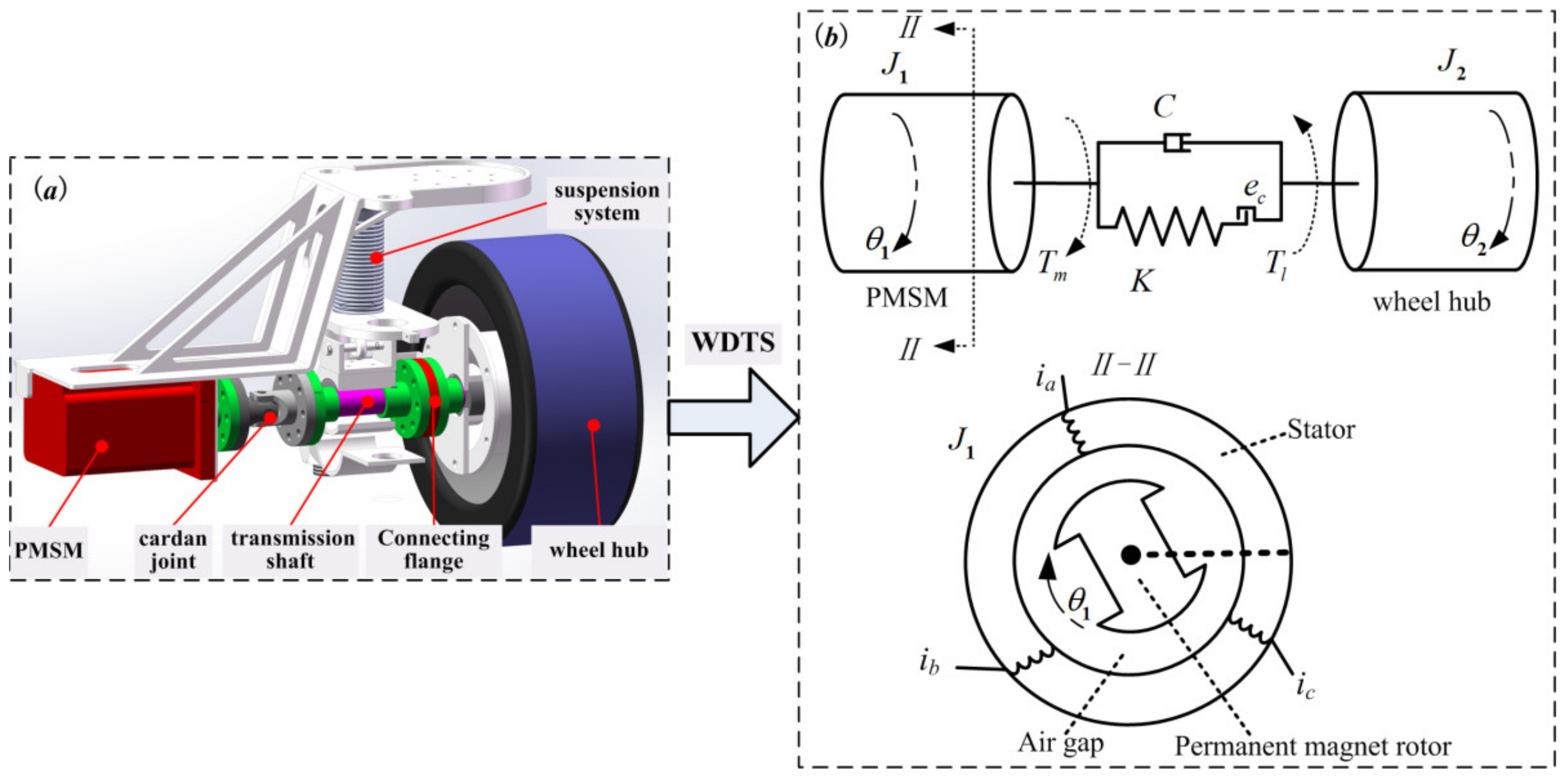
2. System Electromechanical Coupling Dynamics Modelling

The physical model of the WDTS is shown in Figure 1, where the wheel-side direct-driven unit of the electric bus is represented in Figure 1a. The wheel-side direct-driven unit consists of the WDTS and the suspension system. The WDTS mainly includes: the high-power PMSM; the system transmission shaft; the cardan joint; the wheel hub; and other connection accessories. And the WDTS can be equivalent to a mass elastic system [25], composed of several inertial parts and elastic parts, where the elastic parts are used to describe the torsional deformation of the system transmission shaft and the inertial parts are used to describe the impact of system quality.
The equivalent transmission model of the WDTS is shown in Figure 1b. ia, ib, and ic represent the three-phase stator currents of the PMSM, respectively; ua, ub, and uc represent the three-phase stator input voltages of the PMSM, respectively; θ1 and θ2 are the rotation angle of the PMSM and the angle of the wheel hub; J1 and J2 show the equivalent moment of inertia on the PMSM shaft and the moment of inertia of the wheel hub; K and C represent the torsional stiffness and damping coefficient of the system transmission shaft, respectively; ec indicates the system transmission clearance; Tm is the electromagnetic torque of the PMSM; and Tl is the load torque of the wheel hub. Furthermore, the meanings of the symbols used in this paper are listed in Table A1 in Appendix A. The following assumptions are made: (1) the self-inductance and the mutual-inductance of each phase winding of the PMSM are sinusoidal, by ignoring the magnetic saturation and magnetic flux leakage; (2) the influences of the temperature and the frequency change on the PMSM parameters are ignored; and (3) the rotor of the PMSM has no eccentricity and the air gap is uniform.
There are five generalized coordinates of the WDTS. The electromagnetic subsystem includes three parts (e1, e2, and e3), which are the three-phase stator electric charge of the PMSM, and the mechanical subsystem includes two parts (θ1 and θ2), which are the output angles of the PMSM and the wheel hub. The generalized coordinates of the WDTS are shown in Table 1.
The generalized kinetic energy of the WDTS includes the kinetic energy of the mechanical subsystem and the magnetic energy of the electromagnetic subsystem. Among them, the kinetic energy of the mechanical part mainly includes the kinetic energy of the PMSM shaft rotation and the wheel hub rotation, which can be expressed as:
E m = 1 2 J 1 θ ˙ 1 2 + 1 2 J 2 θ ˙ 2 2
The magnetic field energy of the PMSM mainly includes the magnetic energy generated by the three-phase stator current (Wm1) and the magnetic energy generated by the interaction of the flux linkage, caused by the permanent magnet rotor, and the stator current (Wm2), which can be shown as:
W m = 1 2 α α = a , b , c β β = a , b , c L α β i α i β W m 1 + i a ψ f cos θ 1 + i b ψ f cos ( θ 1 2 3 π ) + i c ψ f cos ( θ 1 + 2 3 π ) W m 2 = 1 2 L a i a 2 + 1 2 L b i b 2 + 1 2 L c i c 2 + H i a i b + H i a i c + H i b i c + i a ψ f cos θ 1 + i b ψ f cos ( θ 1 2 3 π ) + i c ψ f cos ( θ 1 + 2 3 π )
where, La, Lb, and Lc are the self-inductance coefficients of the three-phase stator winding of the PMSM; H represents the mutual-inductance coefficient of the three-phase stator winding of the PMSM; and ψ f is the flux linkage of the permanent magnet rotor for the PMSM.
The potential energy of the WDTS is the elastic potential energy caused by the torsional deformation of the transmission shaft. The transmission shaft and the wheel hub are connected by the Birfield ball-joint, and the power of the transmission shaft is transmitted to the Birfield ball-joint through the spline. The wear of the spline during operation will lead to the transmission clearance. Under the direct-driven condition, the influence of the transmission clearance on the system torsional vibration stability is more prominent. The transmission clearance model is considered as [26]:
f θ 1 θ 2 = ( θ 1 θ 2 e c ) + ( θ 1 θ 2 e c ) 3 θ 1 θ 2 > e c > 0 0 e c x e c ( θ 1 θ 2 + e c ) + ( θ 1 θ 2 + e c ) 3 θ 1 θ 2 < e c < 0
Then the system stiffness can be expressed as F k = K f θ 1 θ 2 , and the system potential energy can be shown as:
U m = 1 2 K f 2 θ 1 θ 2
The dissipation function of the WDTS consists of the electromagnetic subsystem consumption and the mechanical subsystem consumption, which can be expressed as:
F c = 1 2 R a i a 2 + 1 2 R b i b 2 + 1 2 R c i c 2 + 1 2 C ( θ ˙ 1 θ ˙ 2 ) 2
where, Ra, Rb, and Rc are the three-phase stator winding resistances of the PMSM, respectively.
The generalized forces of the electromagnetic part are the three-phase stator voltages. The generalized force corresponding to the PMSM angle is its electromagnetic torque (Q4). The generalized force corresponding to the angle of the wheel hub is the load torque (Q5), and the generalized forces of the mechanical part can be represented as:
Q 4 = T m Q 5 = T l
The Lagrange-Maxwell equation [27,28] is:
d d t ( L g q ˙ j ) L g q j + F c q ˙ j = Q k , j = 1 , 2 , 3 , 4 , 5
where, Lg is the Lagrange operator. For the WDTS, Lg can be shown as:
L g = E m + W m U m
By substituting Equations (1) and (2), and (4)–(6) into Equation (7), for the A-phase stator winding, with q1 = e1, the voltage equation can be expressed as:
L a d i a d t + H d i b d t + H d i c d t ψ f θ ˙ 1 sin θ 1 + R a i a = u a
Similarly, for the B-stator winding and the C-stator winding, the voltage equations can be shown as:
L b d i b d t + H d i a d t + H d i c d t ψ f θ ˙ 1 sin ( θ 1 2 3 π ) + R b i b = u b
L c d i c d t + H d i a d t + H d i b d t ψ f θ ˙ 1 sin ( θ 1 + 2 3 π ) + R c i c = u c
For the mechanical part, when the generalized coordinate is the PMSM angle, the motion equation of the PMSM angle is obtained as:
J 1 θ ¨ 1 + C ( θ ˙ 1 θ ˙ 2 ) + K f x = i a ψ f sin θ 1 i b ψ f sin ( θ 1 2 3 π ) i c ψ f sin ( θ 1 + 2 3 π )
Similarly, the motion equation of the wheel hub angle can be obtained as:
J 2 θ ¨ 2 C ( θ ˙ 1 θ ˙ 2 ) K f x = T l
By connecting Equations (9)–(13), the dynamic model for the electromechanical coupling torsional vibration of the WDTS can be shown as:
L a d i a d t + H d i b d t + H d i c d t ψ f θ ˙ 1 sin θ 1 + R a i a = u a L b d i b d t + H d i a d t + H d i c d t ψ f θ ˙ 1 sin ( θ 1 2 3 π ) + R b i b = u b L c d i c d t + H d i a d t + H d i b d t ψ f θ ˙ 1 sin ( θ 1 + 2 3 π ) + R c i c = u c J 1 θ ¨ 1 + C ( θ ˙ 1 θ ˙ 2 ) + K f x = i a ψ f sin θ 1 i b ψ f sin ( θ 1 2 3 π ) i c ψ f sin ( θ 1 + 2 3 π ) J 2 θ ¨ 2 C ( θ ˙ 1 θ ˙ 2 ) K f x = T l
In order to facilitate the theoretical analysis and the numerical calculation, the Clark transform ( C 3 s / 2 s ) and the Park transform ( C 2 s / 2 r ) are introduced to transfer the stator currents of the PMSM from the three-phase static coordinate system to the two-phase rotating coordinate system. And the transformation matrixes are shown as:
C 3 s / 2 s = 2 3 1 1 / 2 1 / 2 0 3 / 2 3 / 2 C 2 s / 2 r = cos θ 1 sin θ 1 sin θ 1 cos θ 1
Then, in the two-phase rotating coordinate, the current equations of the PMSM can be expressed as:
I ˙ D I ˙ Q = R L D L Q L D ω e L D L Q ω e R L Q I D I Q + 0 ψ f L Q ω e + 1 L D 0 0 1 L Q u D u Q
where, uD and ID are the stator direct-axis voltage and current of the PMSM, respectively. uQ and IQ are the stator quadrature-axis voltage and current of the PMSM, respectively. we is the electric angular speed of the PMSM ( ω e = M ω 1 ) and M is the pole-pair of the PMSM. LD and LQ are the D–Q axis inductance component. The PMSM used in our paper is the surface-mounted PMSM and LD = LQ.
The electromagnetic torque equation is expressed as:
T m = 3 2 M ψ D I Q ψ Q I D = 3 2 M ψ f I Q + L D L Q I D I Q = 3 2 M ψ f I Q
Considering that when the angle difference of the transmission shaft is greater than the positive critical value (ec) and less than the negative critical value (−ec), the system dynamics behaviors are similar. Therefore, the dynamic characteristics of the WDTS are considered when the angle difference of the transmission shaft is greater than the positive critical value (ec). Furthermore, by defining ω 1 = θ ˙ 1 , ω 2 = θ ˙ 2 , ϑ = θ 1 θ 2 , and LD = LQ = L, the dynamic model with electromagnetic parameters decoupled of the WDTS of the electric bus can be expressed as:
I ˙ D = u D L R L I D + ω e I Q I ˙ Q = u Q L R L I Q ω e I D ω e L ψ f ϑ ˙ = ω 1 ω 2 ω ˙ 1 = 1 J 1 C ω 1 ω 2 K ( ϑ e c ) + ( ϑ e c ) 3 3 M ψ f 2 I Q ω ˙ 2 = 1 J 2 C ω 1 ω 2 + K ( ϑ e c ) + ( ϑ e c ) 3 + T l

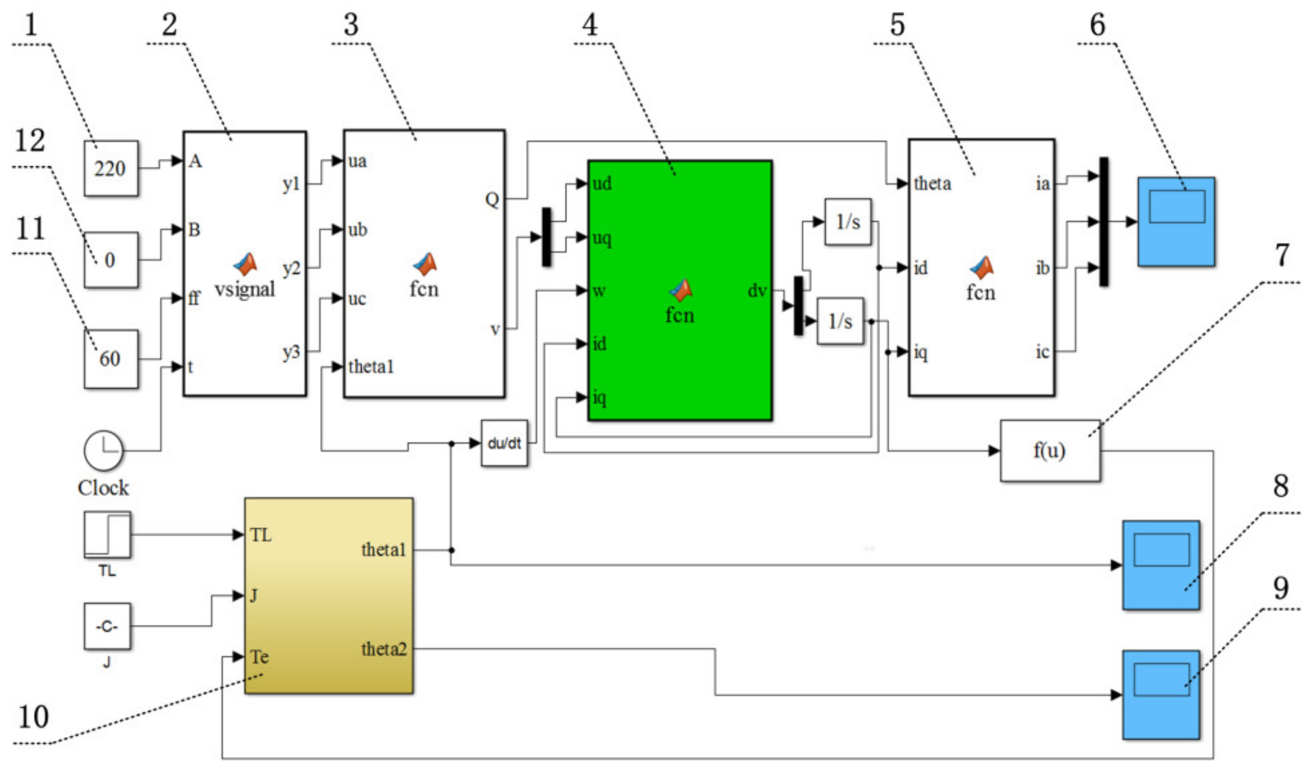
3. System Model Analysis and Verification

Considering that Equation (18) is the nonlinear differential equations, it is difficult to get the analytical solution. Therefore, based on Equation (18), the virtual simulation platform for the WDTS is constructed by MATLAB2015b/Simulink, which is shown in Figure 2. And the numerical simulation analysis of the WDTS is carried out, for the purpose of finding out the system characteristics and providing reference for the PMSM excitation simplification. The physical parameters of the WDTS are shown as: R = 5.60 Ω, L = 0.012 H, ψf = 0.125 Wb, J1 = 25.28 Kg·m2, J2 = 1200 Kg·m2, C = 100 N·m·s/rad, K = 106 N·m/rad, and M = 4 .
The WDTS is driven by the high-power PMSM which is a typical synchronous motor. Thus, under the steady-state operation, the speed formula of the synchronous motor is applied to compare the output speed of the PMSM in the constructed WDTS model. The calculation formula of the synchronous motor speed is ω 1 = 60 f z / M and fz is the stator voltage frequency of the PMSM. The three-phase stator voltage frequencies of the PMSM are given as 10 Hz, 15 Hz, and 20 Hz. Substituting the relevant physical parameters, the stable output speeds of the PMSM should be 150 r/min, 225 r/min, and 300 r/min, according to the calculation formula of the synchronous motor speed. On the virtual simulation platform of the WDTS, when the three-phase stator voltage frequencies of the PMSM are 10 Hz, 15 Hz, and 20 Hz, the output speed curves of the PMSM are obtained as Figure 3.
It is seen from Figure 3 that under the set three-phase stator voltage frequencies, the steady-state values of the PMSM speed by the virtual simulation platform are consistent with the calculation results of the synchronous motor speed calculation formula, which verifies that the constructed WDTS electromechanical coupling dynamic model can play a certain role in simulating the actual system under the steady-state situation.
Moreover, it is obvious that there is a typical non-stationary transition process before the PMSM speed reaches the steady-state value. And the existence of this non-stationary transition process has already been discussed in our previous work [29]. Taking the three-phase stator voltage frequency of the PMSM as 20 Hz, the three-phase stator current curves of the PMSM and the quadrature-axis current curve of the PMSM after coordinate transformation are drawn in Figure 4.
Due to the inductance coefficients, the PMSM itself has inertia effect, and then there is an obvious oscillation phenomenon, during 0–0.15 s, before the PMSM three-phase stator current reaching the stable values in the start-up stage, which is shown in Figure 4a. Also, it is seen from Figure 4b that the quadrature-axis current of the PMSM oscillation converges to a stable value. Because the PMSM output torque is proportional to its quad-rature-axis current, this non-stationary transition process will inevitably affect the PMSM output torque, and then affect the dynamic characteristics of the WDTS.

4. System Model Solving and Resonance Analysis

For the WDTS, the mechanical part and the electrical part are connected by the PMSM output torque. Through the analysis in Section 3, it is found that there is an obvious non-stationary transition process in the start-up stage of the PMSM. Obviously, this non-stationary transition process is related to many factors. And its analytical expression is hard to be established. Thus, as a function can be expanded into the form of Fourier series. Tm is represented as a cosine function for equivalently describing the non-stationary transition process [30]. Then the influences of the temperature and the frequency change on the PMSM dynamic characteristics are ignored [31,32,33]. And the output torque of the PMSM in the start-up stage is taken as:
T m = F cos Ω t
where, F is the initial disturbance amplitude of the PMSM output torque; Ω represents the disturbance frequency.
Through taking x = θ 1 θ 2 , x ˙ = ω 1 ω 2 , and x ¨ = ω ˙ 1 ω ˙ 2 , and subtracting the fifth form from the fourth form of Equation (18), the torsional vibration equation of the WDTS can be obtained as:
x ¨ + μ x ˙ + w 0 2 x b x 2 + a x 3 = F cos Ω t
where, μ = J 1 + J 2 J 1 J 2 C , a = J 1 + J 2 J 1 J 2 K , w 0 2 = J 1 + J 2 J 1 J 2 K 1 + 3 e c 2 , b = 3 J 1 + J 2 J 1 J 2 K e c .
The direct multi-scale method is used to solve Equation (20) [34,35]. Then, a small parameter (ε) is introduced for the nonlinear term of Equation (20), and the new variables are defined as:
T n = ε n t , n = 0 , 1
It is easy to know that the first and second derivatives with respect to t can be expressed as:
d d t = D 0 + ε D 1 + d 2 d t 2 = D 0 2 + 2 ε D 0 D 1 + ε 2 D 1 2 + 2 D 0 D 2
where D i = / T i .
Then, the solution of Equation (20) can be expressed as:
x t , ε = x 0 T 0 , T 1 + ε x 1 T 0 , T 1
where, x0 is the zero-order approximate solution of Equation (20), x1 is the first-order approximate solution of Equation (20).
Through substituting Equations (22) and (23) into Equation (20), the coefficients of ε 0 and ε 1 can be concluded as:
ε 0 : D 0 2 x 0 + w 0 2 x 0 = 0
ε 1 : D 0 2 x 1 + 2 D 0 D 1 x 0 + w 0 2 x 1 + μ D 0 x 0 b x 0 2 + a x 0 3 = F cos Ω T 0
The general solution of Equation (24) can be written as:
x 0 = A k ( T 1 ) exp ( i w 0 T 0 ) + A ¯ k ( T 1 ) exp ( i w 0 T 0 )
where, A ¯ k is the conjugate function of A k ; and i represents the imaginary unit.
The system main resonance is considered, and the tuning parameter is introduced as σ . Then, the disturbance frequency can be defined as:
Ω = w 0 + ε σ
By substituting Equations (26) and (27) into Equation (25), the secular terms are eliminated, and then one can obtain that:
i w 0 2 A k + μ A k 3 a A k 2 A ¯ k 1 2 F exp i σ T 1 = 0
The exponential form of A k is expressed as:
A k = 1 2 p T 1 exp i λ T 1
where p and λ are the amplitude and the phase of Ak, respectively.
By substituting Equation (29) into Equation (28) and separating the real part and imaginary part of the result, the system average equation in polar coordinate form can be obtained as:
p D 1 γ = p σ 3 8 w 0 a p 3 + F 2 w 0 cos γ D 1 p = 1 2 μ p + F 2 w 0 sin γ
where γ = σ T 1 λ .
Therefore, according to Equation (30), the first approximate solution of the system torsional vibration equation can be shown as:
x = p cos w 0 t + λ + o ε
For the stable response of the torsional vibration of the WDTS, it is easy to get that D1p = 0 and D 1 γ = 0 . By eliminating γ from Equation (30), it is obtained that:
9 64 w 0 2 a 2 p 6 3 4 w 0 a σ p 4 + 1 4 μ 2 + σ 2 p 2 F 2 4 w 0 2 = 0
Equation (32) is the resonance curve equation of the torsional vibration response amplitude of the WDTS, which is the function of the tuning parameters, the PMSM torque disturbance excitation amplitude and the system transmission clearance.
Furthermore, the stability of the torsional vibration response of the WDTS is determined by analyzing the singularity of Equation (30). The stable periodic solution is defined as p 0 , γ 0 . And the perturbation variable of the steady periodic solution is introduced as:
p = p 0 + p 1 γ = γ 0 + γ 1 D 1 p = D 1 p 1 D 1 γ = D 1 γ 1
where, p 1 and γ 1 are the small disturbances.
The first-order approximate equation of Equation (30) near the steady-state value is listed as:
D 1 p 1 = 1 2 μ p 1 + 3 8 w 0 a p 0 3 p 0 σ γ 1 D 1 γ 1 = 1 2 μ γ 1 + 1 p 0 σ 9 a 8 w 0 p 0 2
The characteristic equation of Equation (34) is:
κ 2 + μ κ 1 p 0 3 8 w 0 a p 0 3 p 0 σ σ 9 a 8 w 0 p 0 2 + 1 4 μ 2 = 0
Based on the Lyapunov first-order approximate stability criterion [36], because μ is greater than 0, the stability sufficient condition for the steady-state nontrivial solution of the system torsional vibration response of the WDTS is:
1 4 μ 2 1 p 0 3 8 w 0 a p 0 3 p 0 σ σ 9 a 8 w 0 p 0 2 > 0
Figure 5 shows the influence of PMSM torque disturbance amplitude on the amplitude frequency response curve of the main resonance for the torsional vibration of the WDTS. It is seen that with the increase of PMSM torque disturbance amplitude, the main resonance response amplitude of the WDTS increases. And the increase of the PMSM torque disturbance amplitude will not lead to the change of the response curve spine line, which indicates that the increase of the PMSM torque disturbance amplitude will not affect the resonance region of the system torsional vibration.
It is found from Figure 6a that with the increase of the transmission clearance, the resonance region of the amplitude frequency response curve of the main resonance for the system torsional vibration becomes larger, which means that the transmission clearance will exacerbate the torsional vibration instability of the WDTS. And it is shown that when ec = 0, the response curve is basically symmetrical and the resonance frequency is in a very narrow band, corresponding to the linear forced vibration. However, when ec ≠ 0, the response curve is bent, which corresponds to the nonlinear forced vibration. Therefore, when the transmission clearance is considered, the torsional vibration of the WDTS presents complex nonlinear characteristics.
On the other hand, it is found from Figure 6b that the nonlinear forced vibration shows the multivalued nature of the system torsional vibration solution. Within the initial disturbance frequency range of the PMSM, the system torsional vibration response has three solutions, of which there are two stable solutions and one unstable solution, and the amplitude jump and bifurcation phenomenon occurs in this region. Taking ec = 0.005 rad as an example, when the initial disturbance frequency of the PMSM increases gradually, the path of the system amplitude frequency response curve is: ABC. When it reaches the critical point C, with the further increase of the initial disturbance frequency of the PMSM, the system torsional vibration amplitude response jumps from point C to point D. When the initial disturbance frequency of the PMSM decreases gradually, the path of the system amplitude frequency response curve is: DE. When it reaches the critical saddle point E, with the further decrease of the initial disturbance frequency of the PMSM, the system torsional vibration amplitude response skips from point E to point B. This jumping phenomenon of the response amplitudes will cause the fatigue damage to the WDTS of the electric bus, which must be restrained in the practical application.

5. Conclusions

The dynamic model for the electromechanical coupling torsional vibration of the WDTS is constructed. And based on the direct multi-scale method and the Lyapunov first-order approximate stability criterion, the influences of the transmission clearance and the PMSM torque disturbance on the system torsional vibration stability are analyzed. The results are shown as:
(i)
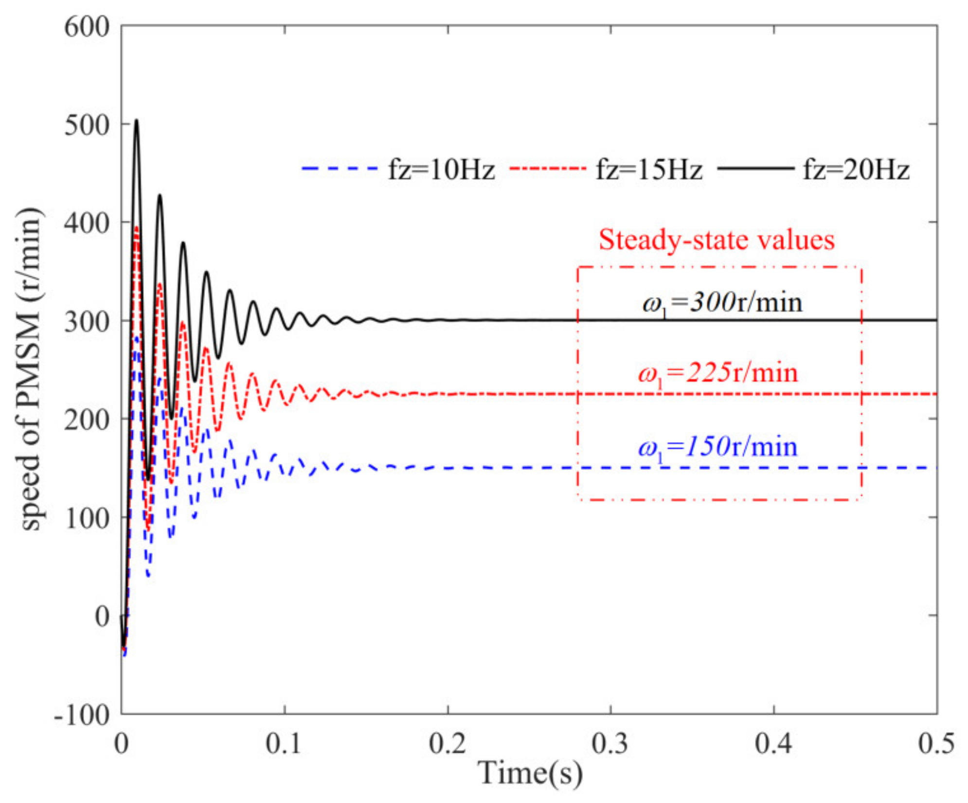
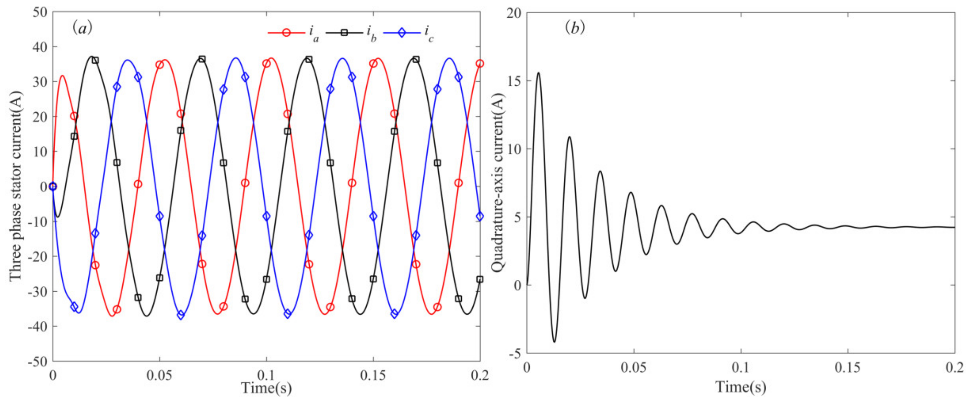
Under the steady-state operation, with the drive voltage signals of different frequencies applied, the numerical results of the PMSM speed of the constructed WDTS dynamic model are consistent with the theoretical calculation results of the synchronous motor speed. Then, the effectiveness of the constructed model is verified;
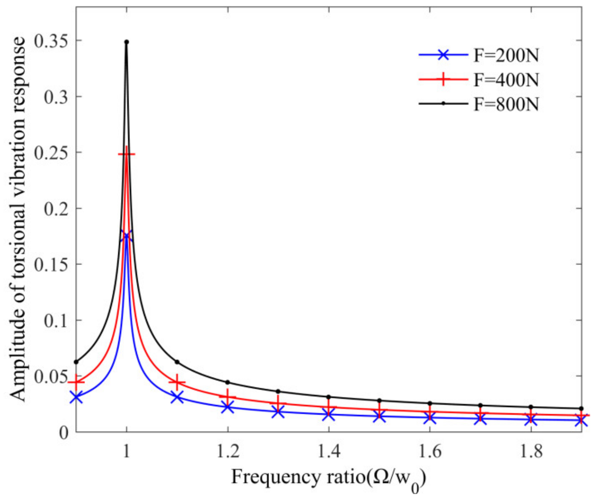
(ii)
For the non-stationary transition process in the start-up stage of the PMSM, a cosine function disturbance excitation is used to describe it. From the amplitude frequency characteristic curve of the system torsional vibration response, it is seen that with the increase of the PMSM torque disturbance amplitude, the main resonance response amplitude of the WDTS will increase, but it will not affect the resonance region of the system torsional vibration, and, in actual application, the PMSM torque disturbance amplitude should be suppressed; and
(iii)
With the increase of the transmission clearance, the system torsional vibration response shows complex nonlinear characteristics, which is manifested by the jump and bifurcation of the system torsional vibration response amplitudes. This phenomenon will cause fatigue damage to the WDTS, which should be effectively suppressed in the actual application. According to the analysis results of this paper, it can provide an important reference for the efficient utilization of the WDTS in the electric bus.

Author Contributions

Conceptualization, J.J. and Y.L.; methodology, J.J.; software, J.J. and C.Z.; validation, J.J. and C.Z.; writing—original draft preparation, J.J.; writing—review and editing, J.J. and Y.L. All authors have read and agreed to the published version of the manuscript.

Funding

This work was partially supported by the National Natural Science Foundation of China (No. 51805001), the Anhui Provincial Natural Science Foundation (No. 1908085QE193) and the Research Starting Fund Project for Introduced Talents of Anhui Polytechnic University (No. 2018YQQ005).

Data Availability Statement

The data used to support the findings of this study are available from the corresponding author upon request.

Conflicts of Interest

The authors declare no conflict of interest.

Appendix A

Table A1. List of symbols.
SymbolsMeanings
J1equivalent moment of inertia on the PMSM shaft
J2moment of inertia of the wheel hub
θ1rotation angle of the PMSM
θ2angle of the wheel hub
uaA-phase stator input voltage of the PMSM
ubB-phase stator input voltage of the PMSM
ucC-phase stator input voltage of the PMSM
iaA-phase stator current of the PMSM
ibB-phase stator current of the PMSM
icC-phase stator current of the PMSM
RaA-phase stator winding resistance of the PMSM
RbB-phase stator winding resistance of the PMSM
RcC-phase stator winding resistance of the PMSM
Laself-inductance coefficient of the a-phase stator winding
Lbself-inductance coefficient of the b-phase stator winding
Lcself-inductance coefficient of the c-phase stator winding
ψ f magnetic potential of the permanent magnet rotor of the PMSM
Ktorsional stiffness of the system transmission shaft
Cdamping coefficient of the system transmission shaft
ecsystem transmission clearance
Tmelectromagnetic torque of the PMSM
Tlload torque of the wheel hub
weelectric angular speed of the PMSM
uDstator direct-axis voltage of the PMSM
IDstator direct-axis current of the PMSM
uQstator quadrature-axis voltage of the PMSM
IQstator quadrature-axis current of the PMSM
fzstator voltage frequency of the PMSM
M pole-pair of the PMSM

References

  1. Dizqah, A.M.; Lenzo, B.; Sorniotti, A.; Gruber, P.; Fallah, S.; De Smet, J. A Fast and Parametric Torque Distribution Strategy for Four-Wheel-Drive Energy-Efficient Electric Vehicles. IEEE Trans. Ind. Electron. 2016, 63, 4367–4376. [Google Scholar] [CrossRef] [Green Version]
  2. Jin, X.J.; Yin, G.; Chen, N. Gain-scheduled robust control for lateral stability of four-wheel-independent-drive electric vehicles via linear parameter-varying technique. Mechatronics 2015, 30, 286–296. [Google Scholar] [CrossRef]
  3. Lin, C.-H. Dynamic control of V-belt continuously variable transmission-driven electric scooter using hybrid modified recurrent legendre neural network control system. Nonlinear Dyn. 2014, 79, 787–808. [Google Scholar] [CrossRef]
  4. Tran, T.H.; French, S.; Ashman, R.; Kent, E. Impact of compressor failures on gas transmission network capability. Appl. Math. Model. 2018, 55, 741–757. [Google Scholar] [CrossRef] [Green Version]
  5. Mirsaeidi, S.; Dong, X.; Said, D.M. A fault current limiting approach for commutation failure prevention in LCC-HVDC transmission systems. IEEE Trans. Power Deliv. 2019, 34, 2018–2027. [Google Scholar] [CrossRef]
  6. Chen, X.; Chen, R.; Deng, T. An investigation on lateral and torsional coupled vibrations of high power density PMSM rotor caused by electromagnetic excitation. Nonlinear Dyn. 2020, 99, 1975–1988. [Google Scholar] [CrossRef]
  7. Bouguenna, I.F.; Azaiz, A.; Tahour, A.; Larbaoui, A. Robust neuro-fuzzy sliding mode control with extended state observer for an electric drive system. Energy 2019, 169, 1054–1063. [Google Scholar] [CrossRef]
  8. Luo, Y.; Liu, C. A Flux Constrained Predictive Control for a Six-Phase PMSM Motor with Lower Complexity. IEEE Trans. Ind. Electron. 2019, 66, 5081–5093. [Google Scholar] [CrossRef]
  9. Jiang, S.; Li, W.; Wang, Y.; Yang, X.; Xu, S. Study on electromechanical coupling torsional resonance characteristics of gear system driven by PMSM: A case on shearer semi-direct drive cutting transmission system. Nonlinear Dyn. 2021, 104, 1205–1225. [Google Scholar] [CrossRef]
  10. Ye, K.; Ji, J. The effect of the rotor adjustment on the vibration behaviour of the drive-train system for a 5 MW direct-drive wind turbine. Proc. Inst. Mech. Eng. Part C J. Mech. Eng. Sci. 2018, 232, 3027–3044. [Google Scholar] [CrossRef]
  11. Alizadeh, O.; Yazdani, A. A Control Strategy for Power Regulation in a Direct-Drive WECS with Flexible Drive-Train. IEEE Trans. Sustain. Energy 2014, 5, 1156–1165. [Google Scholar] [CrossRef]
  12. Mohamed, A. A newly designed instantaneous-torque control of direct-drive PMSM servo actuator with improved torque estimation and control characteristics. IEEE Trans. Ind. Electron. 2007, 54, 2864–2873. [Google Scholar] [CrossRef]
  13. Yang, X.J.; Liu, H.; Yang, Q.Y.; Zhao, W.H. A novel precision evaluation and analysis method for the direct driven high-speed feed system. Mech. Syst. Signal Process. 2019, 121, 689–710. [Google Scholar] [CrossRef]
  14. Bouheraoua, M.; Wang, J.B.; Atallah, K. Rotor position estimation of a pseudo direct-drive PM machine using extended Kalman filter. IEEE Trans. Ind. Appl. 2016, 53, 1088–1095. [Google Scholar] [CrossRef] [Green Version]
  15. Gao, H.; Zhang, Y. Nonlinear behavior analysis of geared rotor bearing system featuring confluence transmission. Nonlinear Dyn. 2014, 76, 2025–2039. [Google Scholar] [CrossRef]
  16. Jiang, X.; Huang, W.; Cao, R.; Hao, Z.; Jiang, W. Electric Drive System of Dual-Winding Fault-Tolerant Permanent-Magnet Motor for Aerospace Applications. IEEE Trans. Ind. Electron. 2015, 62, 7322–7330. [Google Scholar] [CrossRef]
  17. Lu, E.; Li, W.; Yang, X.F.; Xu, S.Y. Simulation study on speed control of permanent magnet direct-driven system for mining scraper conveyor. Int. J. Eng. Syst. Model. Simul. 2018, 10, 1–11. [Google Scholar] [CrossRef]
  18. Tang, X.; Yang, W.; Hu, X.; Zhang, D. A novel simplified model for torsional vibration analysis of a series-parallel hybrid electric vehicle. Mech. Syst. Signal Process. 2017, 85, 329–338. [Google Scholar] [CrossRef]
  19. Han, X.; Palazzolo, A.B. VFD machinery vibration fatigue life and multilevel inverter effect. IEEE Trans. Ind. Appl. 2013, 49, 2562–2575. [Google Scholar] [CrossRef]
  20. Shen, C.R.; Lu, C.H. A refined torsional-lateral-longitude coupled vehicular driveline model for driveline boom problems. Appl. Math. Model. 2021, 90, 1009–1034. [Google Scholar] [CrossRef]
  21. Sopanen, J.; Ruuskanen, V.; Nerg, J.; Pyrhonen, J. Dynamic torque analysis of a wind turbine drive train including a direct-driven permanent-magnet generator. IEEE Trans. Ind. Electron. 2011, 58, 3859–3867. [Google Scholar] [CrossRef]
  22. Zhang, X.J.; He, W.; Hu, J.B. Impact of inertia control of DFIG-based WT on torsional vibration in drivetrain. IEEE Trans. Sustain. Energy 2020, 11, 2525–2534. [Google Scholar] [CrossRef]
  23. Chen, X.; Peng, D.; Hu, J.B.; Li, C.; Zheng, S.L. Adaptive torsional vibration active control for hybrid electric powertrains during start-up based on model prediction. Proc. Inst. Mech. Eng. Part D J. Automob. Eng. 2021, 09544070211056176. [Google Scholar] [CrossRef]
  24. Sheng, L.C.; Li, W.; Jiang, S.; Chen, J.J.; Liu, A. Nonlinear torsional vibration analysis of motor rotor system in shearer semi-direct drive cutting unit under electromagnetic and load excitation. Nonlinear Dyn. 2019, 96, 1677–1691. [Google Scholar] [CrossRef]
  25. Lozynskyy, A.; Chaban, A.; Perzyński, T.; Szafraniec, A.; Kasha, L. Application of fractional-order calculus to improve the mathematical model of a two-mass system with a long shaft. Energies 2021, 14, 1854. [Google Scholar] [CrossRef]
  26. Liu, S.; Wang, J.J.; Liu, J.J.; Li, Y.Q. Nonlinear parametrically excited vibration and active control of gear pair system with time-varying characteristic. Chin. Phys. B 2015, 24, 104501. [Google Scholar] [CrossRef]
  27. Ju, J.J.; Li, W.; Wang, Y.Q.; Fan, M.B.; Yang, X.F. Dynamics and nonlinear feedback control for torsional vibration bifurcation in main transmission system of scraper conveyor direct-driven by high-power PMSM. Nonlinear Dyn. 2018, 93, 307–321. [Google Scholar] [CrossRef]
  28. Liu, S.; Ai, H.; Sun, B.; Li, S.; Meng, Z. Bifurcation and chaos of electromechanical coupling main drive system with strongly nonlinear characteristic in mill. Chaos Solitons Fractals 2017, 98, 101–108. [Google Scholar] [CrossRef]
  29. Ju, J.J.; Li, W.; Yang, X.F.; Wang, Y.Q.; Liu, Y.F. Electromechanical coupling vibration characteristics of an AC servomo-tor-driven translational flexible manipulator. Int. J. Adv. Robot. Syst. 2016, 13, 1–10. [Google Scholar] [CrossRef] [Green Version]
  30. Liu, Y.F.; Li, W.; Yang, X.F.; Fan, M.B.; Wang, Y.Q. Vibration response and power flow characteristics of a flexible manipulator with a moving base. Shock. Vib. 2015, 2015, 589507. [Google Scholar] [CrossRef] [Green Version]
  31. Si, J.; Zhao, S.Z.; Feng, H.C.; Hu, Y.H.; Cao, W.P. Analysis of temperature field for a surface-mounted and interior permanent magnet synchronous motor adopting magnetic-thermal coupling method. CES Trans. Electr. Mach. Syst. 2018, 2, 166–174. [Google Scholar] [CrossRef]
  32. Liang, D.; Li, J.; Qu, R. Sensorless control of permanent magnet synchronous machine based on second-order sliding-mode observer with online resistance estimation. IEEE Trans. Ind. Appl. 2017, 53, 3672–3682. [Google Scholar] [CrossRef]
  33. Wang, Z.H.; Lu, Q.F.; Ye, Y.Y.; Lu, K.Y.; Fang, Y.T. Investigation of PMSM Back-EMF using sensorless control with parameter variations and measurement errors. Przeglad Elektrotechniczny 2012, 88, 182–186. [Google Scholar]
  34. Abdulle, A.; Grote, M.J.; Stohrer, C. Finite element heterogeneous multiscale method for the wave equation: Long-time effects. Multiscale Modeling Simul. 2014, 12, 1230–1257. [Google Scholar] [CrossRef] [Green Version]
  35. Budarapu, P.R.; Gracie, R.; Bordas, S.P.A.; Rabczuk, T. An adaptive multiscale method for quasi-static crack growth. Comput. Mech. 2014, 53, 1129–1148. [Google Scholar] [CrossRef] [Green Version]
  36. Naik, R.D.; Mhalsekar, S.D. Bound on amplitude of a MEMS resonator by approximating the derivative of the lyapunov function in finite time. Int. J. Struct. Stab. Dyn. 2021, 21, 2171003. [Google Scholar] [CrossRef]
Figure 1. Physical model of the WDTS: (a) wheel-side direct-driven unit; and (b) equivalent transmission model of the WDTS.
Wevj 13 00046 g001
Figure 2. Virtual simulation platform of the WDTS: 1. Voltage amplitude; 2. Voltage transmitter module; 3. Coordinate positive transformation module (C3s/2s + C2s/2r); 4. PMSM module; 5. Inverse coordinate transformation module; 6. Three-phase stator current display module; 7. Torque conversion module; 8. PMSM speed display module; 9. wheel hub speed display module; 10. Motion equation module; 11. Voltage frequency; 12. Voltage initial phase.
Wevj 13 00046 g002
Figure 3. Output speeds waveform diagram of the PMSM under different voltage frequencies in the virtual simulation platform of the WDTS.
Wevj 13 00046 g003
Figure 4. Three-phase stator current and quadrature-axis current curves of the PMSM in the start-up phase (fz = 20 Hz): (a) three-phase stator current; and (b) quadrature-axis current.
Wevj 13 00046 g004
Figure 5. Influence of PMSM torque disturbance amplitude on the amplitude frequency response curve of the main resonance for the torsional vibration of the WDTS.
Wevj 13 00046 g005
Figure 6. Influence of the transmission clearance on the amplitude frequency response curve of the main resonance for the torsional vibration of the WDTS: (a) influence law of different transmission clearance; and (b) amplitude jump phenomenon.
Wevj 13 00046 g006
Table 1. Generalized coordinates of the WDTS.
Generalized
Coordinates
Electromagnetic SubsystemMechanical Subsystem
Stator
of the PMSM
Output Angles
of the PMSM
Output Angles
of the Wheel Hub
j = 1j = 2j = 3j = 4j = 5
qje1e2e3 θ 1 θ 2
q ˙ j iaibic θ ˙ 1 θ ˙ 2
Q j uaubucTmTl
Publisher’s Note: MDPI stays neutral with regard to jurisdictional claims in published maps and institutional affiliations.

