Abstract
Precise motor speed regulation control is essential to achieve a good gear shifting quality of the integrated motor-transmission (IMT) system, in which the relative speed between outgoing shaft and the gearwheel to be engaged can be eliminated directly through regulation of the motor speed. The speed regulation control confronts the difficulty that there exist external disturbances on the motor shaft, like the unknown load torque arised from bearing friction, oil shearing and oil churning, etc. To deal with these disturbances, a robust speed regulation controller combined a nominal proportional control and integral sliding mode control is proposed. The former is designed to achieve a good speed tracking performance and the latter provides functionality of disturbances rejection. The effects of different controller parameters for the robust controller design are assessed via simulations. Moreover, to verify the effectiveness of the combined control scheme in practical engineering use, experiments are carried out on a test bench with a real IMT powertrain system. Results indicate that the proposed approach can attain a rapid and smooth speed regulation process with a simple controller structure and good robustness.
1. Introduction
Precise motor speed regulation control is essential for the gear shifting process in multiple speed transmissions without power-on gearshift capacity [1,2,3,4,5]. In clutchless automated manual transmission (CLAMT) for battery electric vehicle (BEV), the electric motor is expected to achieve precise speed matching before engaging the synchronizer. For the IMT powertrain system adopted in hybrid electric vehicle (HEV), under the pure electric-driving mode, the fast and smooth gearshift process relies on an accurate and reliable motor speed control. The relative speed between two sides of the synchronizer is eliminated through regulation of the motor speed, rather than clutch-clutch gearshift.
The speed regulation control in gearshift process for CLAMT has been widely studied in the current literature. According to the experiment tests, the expense time of the speed regulation phase can account for almost half of the total gearshift time and the relative speed after regulation can influence the gear engagement performance [6,7]. For conventional motor speed control, proportional-integral-derivative (PID) control is often utilized [3,8,9]. However, tuning of the PI control gains is time-consuming and the conventional PI controller is also usually lack of robustness. In practical applications, although the gears and synchronizers are totally released, the speed regulation process can be easily affected by external disturbances, i.e., the unknown load torque on the motor shaft arisen from bearing friction, oil shearing and oil churning, etc. To deal with the problem, the common practice is to integrate robust controller design with a nominal control part. To make the control scheme be concise and easy to use in real application, a generalized proportional-integral (PI) control was adopted for speed tracking, while an energy-to-peak control was used to guarantee the robustness of the proposed controller against external disturbance [10]. In Ref [7], Zhu et al. combined preview control, integral control, and state-feedback control together for speed regulation control of a CLAMT system. The system performance was influenced by the preview step, the pole placement and the weighting matrices of the performance index. However, the setting process for these control parameters was somehow time-consuming and complicated. Similar control schemes were also applied to design the speed controller in Refs [11,12,13,14]. However, the control has to trade-off between robustness and transient performances, which can lead to an over-conservative approach. Yu and co-workers [15,16,17] introduced the sliding-mode technique to enhance the speed regulation control capability despite external uncertainties. Moreover, a thin boundary layer of the sliding surface was used to avoid the chattering phenomenon on the switching surface. A co-design scheme for networked speed regulation control combined a discrete-time sliding mode control and active period scheduler were presented in Ref [18], where the active period scheduler was used to actively adjust the system’s sampling period. Apart from these common robust control techniques, other methods like dynamic model reference control [19] and observer-based control [20] are also observed.
To get a simple and intuitive controller structure and simplify the controller parameter tuning process while maintaining desired performance and robustness, a robust speed regulation controller for the gear shifting process control of the IMT powertrain system is designed in this paper. The control effort is contributed by nominal proportional (P) control and integral sliding mode (ISM) control. The former is to tackle the zero static error control based on the nominal model, while the ISM control is used to enhance the robustness of the controller in the presence of external disturbances. The outline of this paper is as follows. Section 2 analyses the gear shifting process and abstracts a fixed-point tracking control problem from the speed regulation phase. Section 3 presents the development process of the combined speed regulation controller. In Section 4, the effectiveness of the proposed control scheme is verified through simulations and experiments, and is compared with the conventional PI controller. Finally, conclusions are summarized in Section 5.
2. Problem Formulation
2.1. Gear Shifting Process of the IMT under Electric-Driving Mode
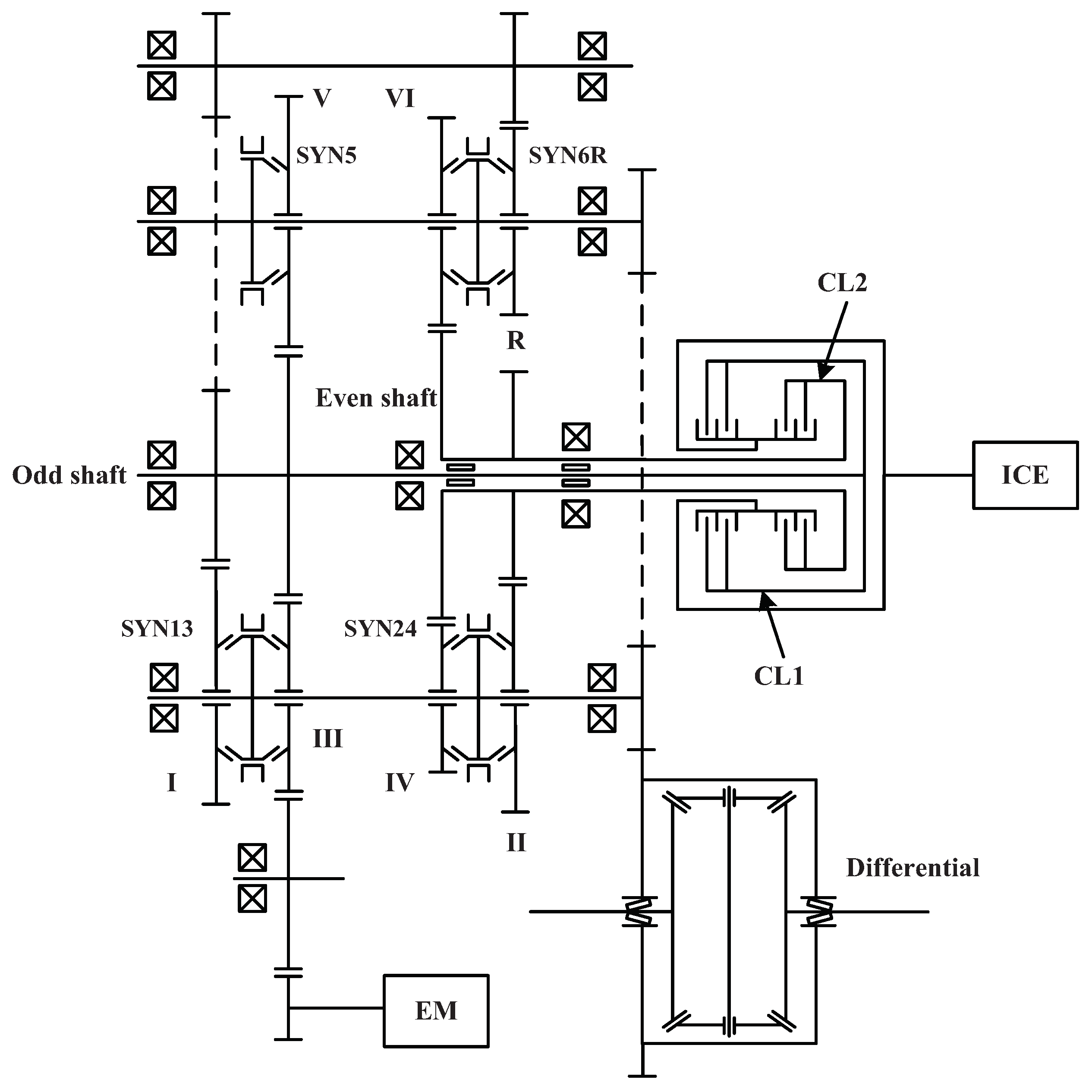
Figure 1 shows the structural details of the IMT system. The IMT can be regarded as one type of the dedicated hybrid transmission, where the electric motor is coupled to the odd shaft of a 6-speed DCT. The plug-in hybrid electric vehicle equipped with such an IMT powertrain system will run on electric-driving mode before the state of charge (SOC) of the battery dropped to a pre-set threshold. Note that for the case of electric-driving mode, the ICE is mechanically decoupled from the remainder of the powertrain with clutches CL1 and CL2 disengaged. Thus, the gear shifting process only involves with the electric motor and synchronizer.

Figure 1.
Schematic diagram of the IMT system (EM: electric motor; ICE: internal combustion engine; SYN: synchronizer; CL: clutch).
The gear shift control tactic can be subdivided into four phases. Gear release phase: reduce the motor torque to the threshold value and switch the synchronizer to neutral position. Speed regulation phase: regulate the motor speed to the target value. Gear engagement phase: engage the on-coming gear. Torque recovery phase: restore the motor torque. This paper focuses on the second phase and the main concern is to achieve a short speed regulation process duration and small steady-state speed track error in the presence of disturbances.
2.2. System Modelling of the Speed Regulation Phase
The simplified powertrain model of the IMT system under electric-driving mode is presented in Figure 2, where is the equivalent inertia converted to the motor output shaft, is the motor torque, is the motor speed, is the equivalent viscous damping coefficient at the motor shaft, represents the external disturbances like the unknown load torque which may come from bearing friction, oil drag and air drag, etc. is the equivalent inertia converted to the transmission output shaft, is the equivalent vehicle resistance, and is the transmission output shaft speed which is proportional to the wheel speed with the final drive ratio.
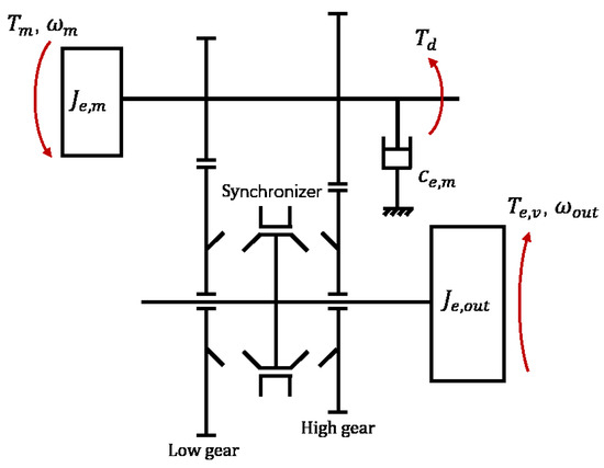
Figure 2.
Dynamic model of the IMT system under electric-driving mode.
According to the description of Section 2.1, all the synchronizers and clutches are fully disengaged during the speed regulation phase and the IMT system is degenerated into a two degree of freedom system. Applying the Newtonian mechanics, the dynamic equations of the simplified powertrain system during this phase can be developed as
Note that the equivalent inertia is comparatively large and the gear shifting duration is short, will be almost kept unchanged. In the IMT system, the motor is mechanically connected to the driven part of the synchronizer mechanism. Hence, the relative speed between the two sides of the synchronizer can be regulated by controlling the motor torque. To simplify the modelling process, the electric motor dynamic can be expressed as a first-order inertial element with the following equation
where is the motor torque command, is the time constant, and is the gain. Then, a fixed-point tracking control problem can be abstracted from the regulation process and the reference signal is the motor target speed, which can be described as
where is the target motor speed and is the gear ratio of the on-coming gear level. When upshifting from the low gear to high gear with gear ratio reduced, the initial motor speed is faster than the target motor speed, so the motor speed is required to reduce to the target value. While for the downshifting scenario, the motor speed should increase to the target value.
3. Controller Design
A feedback-based combined speed regulation controller for the above tracking control problem is proposed. As illustrated in Figure 3, the control effort is contributed by two parts, namely nominal proportional (P) control and integral sliding mode (ISM) control. The speed-tracking error between the measured motor speed and the reference speed is the feedback signal. The P control is to tackle the zero static error control based on the nominal model. As mentioned before, there exist external disturbances like unknown load torques or plant parameter drift in practical engineering application. To eliminate the disturbances in the speed regulation process, the ISM control is used to enhance the robustness of the controller.
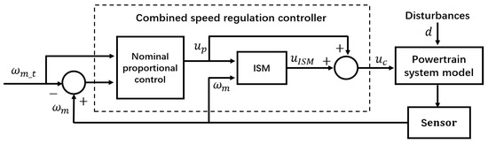
Figure 3.
Schematic diagram of the combined speed regulation controller.
3.1. Nominal P Control Design in the Absence of the Disturbances
The Equation (1) can be converted as (assuming the external disturbances to be zero)
where u denotes the motor torque, and are coefficients of the system and can be calculated from the powertrain system parameters.
Let the linear feedback control input be given by
where k is the feedback gain and p is the coefficient of the compensation term related to the reference input . The parameters k and p can be obtained by the following analysis.
The speed-tracking error is defined as
If the feedback gain k is chosen such that , the speed-tracking error system represented by Equation (9) is BIBO stable. The reference signal is constant, then the speed-tracking error system is also asymptotically stable.
The explicit solution of Equation (9) is
with
where is the measured motor speed at the beginning of the speed regulation phase. According to Equation (10), the steady-state error value can be approximated as the constant term as the time tends to infinity. To compensate the steady-state error, the constant term can be eliminated by selecting .
Thus Equation (10) can be simplified as
The convergence rate of the speed-tracking error depends on the value of the feedback gain. Assuming that the terminal time is T and the speed-tracking error decreases from to a certain level (set at 1 r/min), a quantitative relationship between the feedback gain k and the performance index T can be obtained from Equation (11) as
Therefore, the unknown control parameters in Equation (6) can be determined with the given performance index T, and the nominal control law can be rewritten as
3.2. The Equivalent ISM Control Design Considering the Disturbances
The above nominal controller design process assumes no disturbances, which is not consistent with the actual application scenario. The unknown load torques and model parameters mismatch can deteriorate control performance, sometimes these uncertainties and disturbances may cause unstable and oscillation. To make the transient response of the motor speed has the prescribed nominal dynamics, an integral sliding mode controller is integrated with the nominal control part. Considering the presence of disturbances, the Equation (5) can rewritten as
where d represents the disturbances and satisfies the matching condition. Assuming that d has an upper bound, i.e.,
The trajectory of the ideal system () with the nominal control law can be given by the solutions of the following equation
By comparing Equations (14) and (16), it is observed that the nominal trajectory is achieved only if the equivalent control of the ISM can compensate the disturbances.
Let the combined control be given by
where is the ISM control part guarantying the compensation of the disturbances from the very beginning of the control action.
The sliding manifold is given by means of the equation with S defined by the formula
Taking the derivate of Equation (19) and we obtain
In order to achieve the sliding mode, the ISM control part should be designed as
with
Therefore,
That is, the ISM control law given in Equations (19) and (21) satisfy the existence conditions of the sliding mode and the sliding mode is achieved from the beginning.
In summary, the combined control law is given as
4. Results
4.1. Simulation Results
4.1.1. Simulation Setup
To verify the validity and performance of the proposed speed regulation control scheme, the simulation model is built in MATLAB/Simulink environment. The key parameters used for the controller design are described in Table 1.

Table 1.
Powertrain system parameters.
As mentioned before, we assume that the external disturbance is the matched uncertainty. The nominal trajectory is obtained from the P control law and the ISM control is to ensure the insensitivity of the trajectory tracking with respect to the matched disturbances starting from the initial time moment. Even though the electric motor is separated from the output shaft in the speed regulation process, there exists external disturbance torque on the motor shaft, which is mainly form the friction or oil drag torque. To examine the robustness of the proposed ISM, the external load torque is simulated as a band-limited white noise. Furthermore, the actual speed regulation process of the IMT powertrain system may also be affected by parameters drift from the nominal model, discretization error of the commands and measurements, time delays induced by the network, etc. These factors are considered in the simulating process and can set up as follows: (a) the nominal model parameters and listed in Table 1 are perturbed to and , (b) the measurement noises in the speed sensor are modelled with uniform random numbers, and (c) time delays in communication channels are simulated with a transport delay block in Simulink.
4.1.2. Simulation Results Analysis
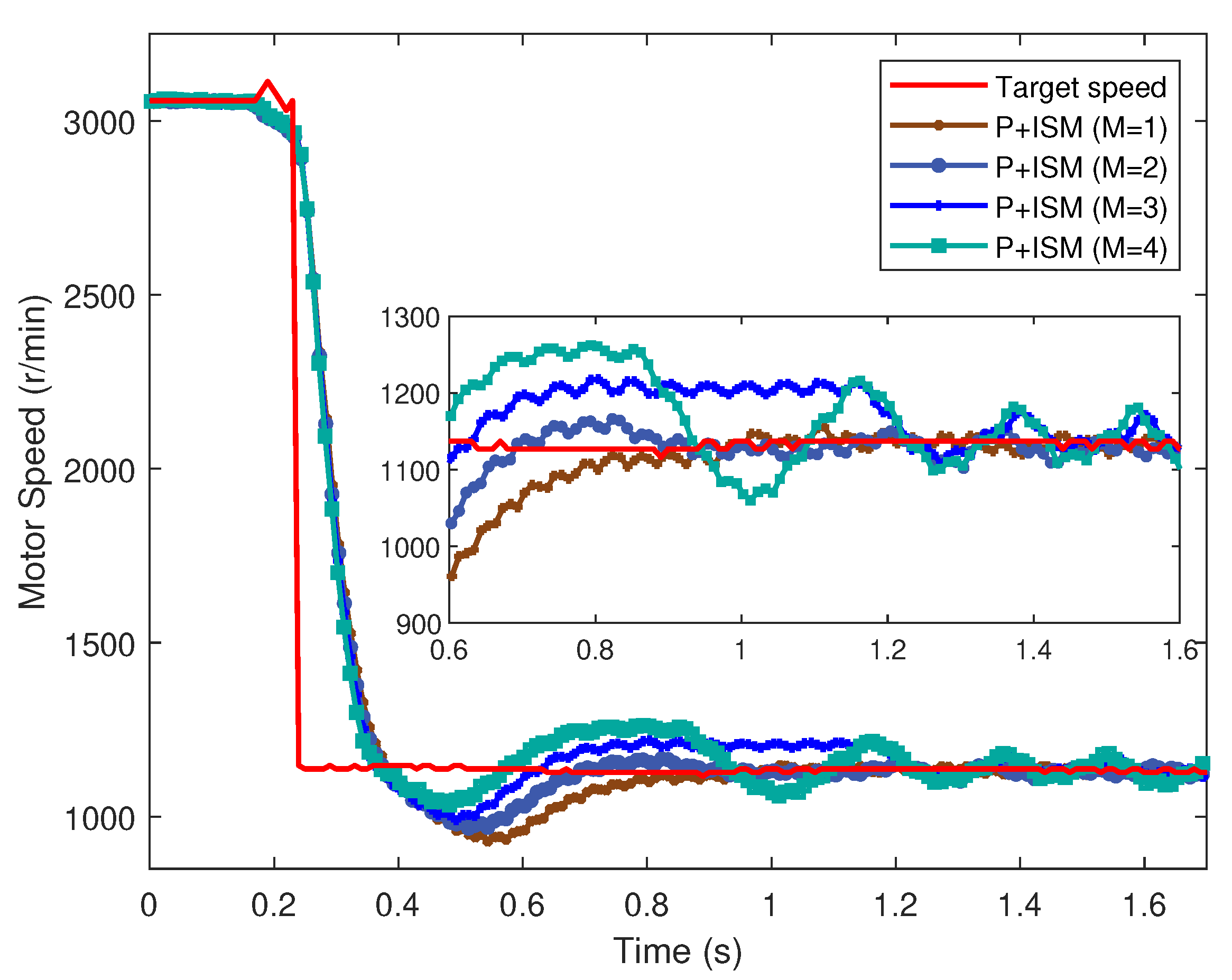
When the gears change from the first gear to the third gear, the motor speed is required to decrease from 3058 r/min to 1135 r/min and the downshift process is reversed. In the simulating process, the performance index T in Equation (13) is set to 0.2 s, thus the nominal P control parameters can be determined.
Effects of different ISM control parameters M are shown in Figure 4. From the zoom-in results of the motor speed and torque responses, we find that, the ISM control fails to adjust motor speed to the target value if M is set to 1 and 2. The reason is that the M violates Equation (22), that is, M is smaller than the upper bound of the disturbances which means the existence condition of the sliding mode given in Equation (23) cannot be satisfied. When M is set to 3, the motor speed can be adjusted to the target speed and the regulation time roughly coincides with the pre-set time T ( 0.2 s), meanwhile the steady tracking error is limited to within the range from −15 r/min to 15 r/min. If M is further increased to 4, the motor speed and torque fluctuates greatly and the steady speed-tracking error is outside the given boundaries. Generally speaking, the choice of M should be in accordance with the characteristics of the external disturbances and need to calibrate through simulations.
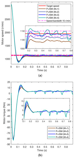
Figure 4.
The speed regulation process in the upshift scenario with different control parameters (a) speed regulation performances; (b) motor torque command.
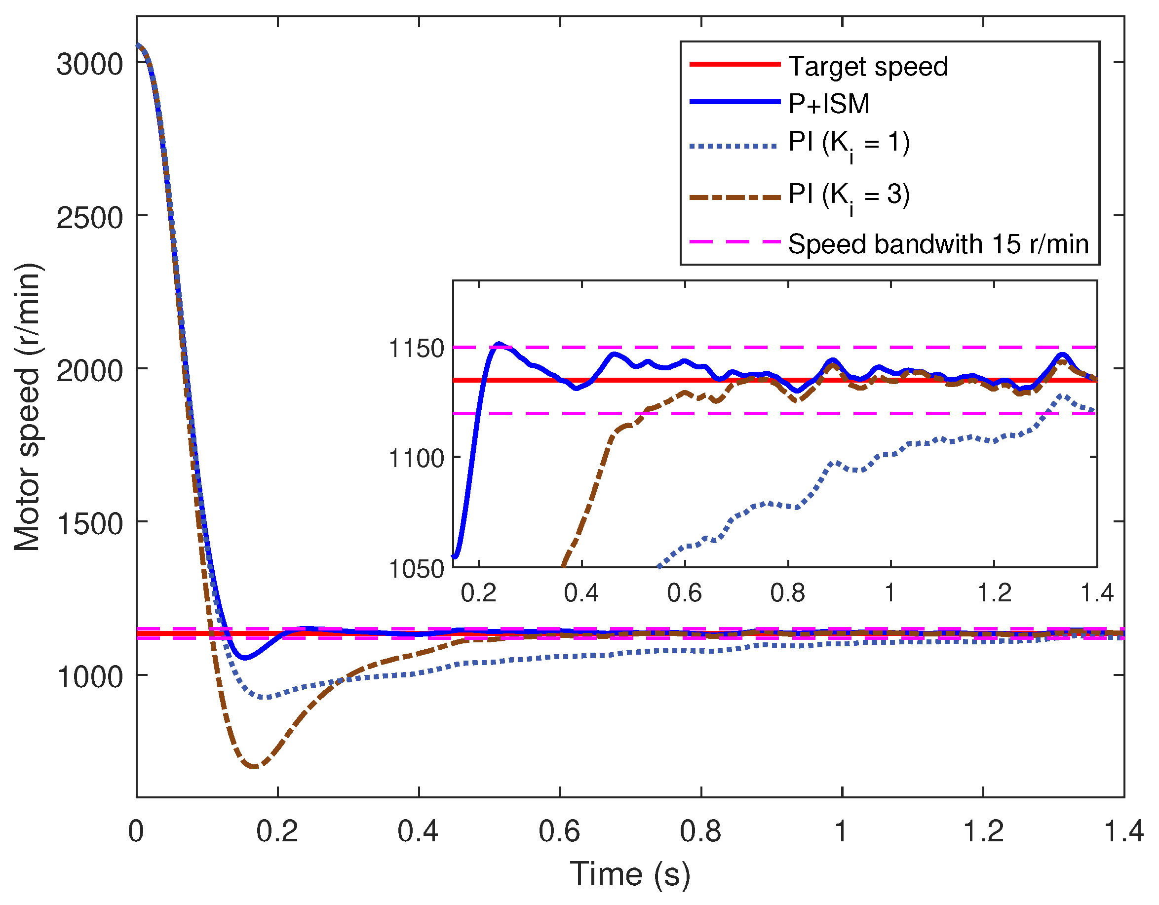
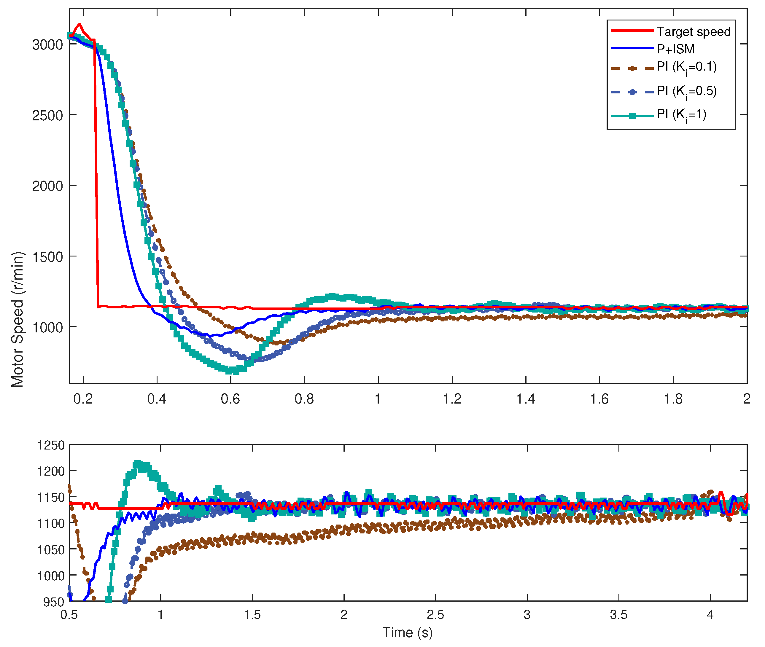
Figure 5 compares the speed responses of the proposed controller with PI cascade speed controller. From the zoom-in results, it can be seen that the speed regulation process is very fast with the proposed control compared with the PI cascade speed control. For PI cascade controller, when is set to 1, the process to eliminate the speed-tracking error becomes very slow. If increases to 3, a great overshoot of the motor speed responses occurs.

Figure 5.
Motor speed responses on the basis of P+ISM controller and PI cascade controller.
4.2. Experiment Validation
To verify the feasibility of the proposed speed regulation control method in practical applications, a test bench based on the IMT powertrain system is set up, as is shown in Figure 6, and the structural details of the transmission apparatus have been illustrated in Figure 1. The dynamometer is coupled to the output shaft to apply the load and the flywheel is to emulate the vehicle inertia. The proposed algorithm is compiled and deployed into the MicroAutoBox simulator. The communication between the motor control unit (MCU), transmission controller unit (TCU) and the simulator is based on CAN. Note that the CAN communication rate is set to 10 ms and the performance index T is set to 0.5 s here.
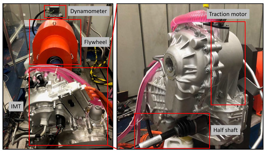
Figure 6.
Experimental test bench of the study.
Through the simulations, it is clear that only choosing a suitable M can obtain an ideal speed regulation response. Figure 7 gives experiment results for the proposed controller with different M. Contrary to Figure 5, in the real upshift scenario, the three set of parameters can all achieve the motor speed regulation process, which implies is bigger than the upper bound of the disturbances in this experimental case. As seen in the zoom-in results, when M increases, the chattering amplitude of the motor speed around the target value also increases.
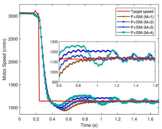
Figure 7.
Experiment results for the proposed controller with different M.
Finally, the proposed control is compared with the conventional PI cascade speed control. According to Figure 8, it is evident that the motor speed responses have a good performance if the proposed control scheme is applied. Selecting a set of suitable for the PI controller is a time-consuming and complicated process. Coinciding with the analysis in Section 4.1.2, if the is smaller, the time to eliminate the speed-tracking error increases. while a bigger can reduce the settling time but cause severe overshoot.
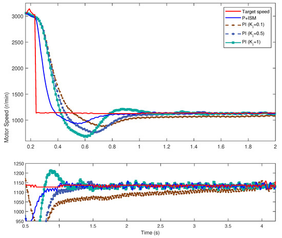
Figure 8.
Experiment results for the proposed controller and PI.
5. Conclusions
The speed regulation phase of the gear shifting process in the IMT powertrain system confronts the difficulty that there exist external disturbances. In this paper, a robust speed regulation controller which combines the nominal P control and the ISM control is proposed. Through the analysis of the gear shifting process, the speed regulation phase control is simplified to a tracking control problem. The nominal P control can obtain the zero static error control based on the nominal model and the control parameters can be easily determined with the given performance index. In the presence of the disturbances, the ISM control can guarantee the compensation of the disturbances from the very beginning of the control action. Simulation and experiment results demonstrate the proposed control scheme exhibit improvement over the PI cascade speed control, both in overshoot and in speed regulation phase duration. The combined control scheme has a simple and intuitive controller structure and simplify the controller parameter tuning process than the conventional PI controller.
Author Contributions
Conceptualization, W.H. and J.H.; Data curation, W.H.; Funding acquisition, C.Y.; Methodology, W.H. and J.H.; Project administration, C.Y.; Validation, W.H. and and J.H.; Writing—original draft, W.H. and J.H.; Writing—review & editing, C.Y. All authors have read and agreed to the published version of the manuscript.
Funding
This research was funded by the National Key Technology R & D Program of China, grant number 2015BAG04B01.
Conflicts of Interest
The authors declare no conflict of interest.
Abbreviations
The following abbreviations are used in this manuscript:
| IMT | Integrated motor-transmission |
| CLAMT | Clutchless automated manual transmission |
| ISM | Integral sliding mode |
| Equivalent inertia of the motor shaft | |
| Equivalent inertia of the transmission output shaft | |
| Lumped viscous damping coefficient | |
| Motor dynamic gain | |
| Motor dynamic time constant | |
| Gear ratio of the target gear | |
| Motor torque | |
| External disturbances | |
| Equivalent vehicle resistance | |
| Motor torque command | |
| Motor speed | |
| Transmission output shaft speed | |
| Target motor speed | |
| Initial motor speed | |
| Nominal speed trajectory | |
| Proportional control law | |
| Integral sliding mode control law | |
| Combined control law | |
| k | Feedback gain |
| p | Compensation gain |
| e | Speed tracking error |
| T | Terminal time |
| Specific error bandwidth | |
| d | Matched disturbances |
| Upper bound of disturbance | |
| S | Sliding manifold |
| M | Sliding mode control parameter |
References
- Maguire, J.; Peng, H.; Bai, S. Dynamic Analysis and Control System Design of Automatic Transmissions; SAE International: Warrendale, PA, USA, 2013. [Google Scholar]
- Tian, Y.; Ruan, J.; Zhang, N.; Wu, J.; Walker, P.D. Modelling and control of a novel two-speed transmission for electric vehicles. Mech. Mach. Theory 2018, 127, 13–32. [Google Scholar] [CrossRef]
- Tian, Y.; Zhang, N.; Zhou, S.; Walker, P.D. Model and gear shifting control of a novel two-speed transmission for battery electric vehicles. Mech. Mach. Theory 2020, 152, 103902. [Google Scholar] [CrossRef]
- Ahssan, R.; Ektesabi, M.; Gorji, S.A. Electric Vehicle with Multi-Speed Transmission: A Review on Performances and Complexities. SAE Int. J. Altern. Powertrains 2018, 7, 169–181. [Google Scholar] [CrossRef]
- Mo, W.; Walker, P.D.; Fang, Y.; Wu, J.; Ruan, J.; Zhang, N. A novel shift control concept for multi-speed electric vehicles. Mech. Syst. Signal Process. 2018, 112, 171–193. [Google Scholar] [CrossRef]
- Liu, H.; Lei, Y.; Li, Z.; Zhang, J.; Li, Y. Gear-Shift Strategy for a Clutchless Automated Manual Transmission in Battery Electric Vehicles. SAE Int. J. Commer. Veh. 2012, 5, 57–62. [Google Scholar] [CrossRef]
- Zhu, X.; Zhang, H.; Xi, J.; Wang, J.; Fang, Z. Robust speed synchronization control for clutchless automated manual transmission systems in electric vehicles. Proc. Inst. Mech. Eng. Part D J. Automob. Eng. 2014, 229, 424–436. [Google Scholar] [CrossRef]
- Shyam, A.; Febin Daya, J.L. A comparative study on the speed response of BLDC motor using conventional PI controller, anti-windup PI controller and fuzzy controller. In Proceedings of the 2013 International Conference on Control Communication and Computing (ICCC), Thiruvananthapuram, India, 13–15 December 2013; pp. 68–73. [Google Scholar] [CrossRef]
- Walker, P.D.; Fang, Y.; Zhang, N. Dynamics and Control of Clutchless Automated Manual Transmissions for Electric Vehicles. J. Vib. Acoust. 2017, 139, 061005. [Google Scholar] [CrossRef]
- Zhu, X.; Zhang, H.; Fang, Z. Speed synchronization control for integrated automotive motor–transmission powertrain system with random delays. Mech. Syst. Signal Process. 2015, 64, 46–57. [Google Scholar] [CrossRef]
- Rajendran, A.; Padma, S. H-infinity robust control technique for controlling the speed of switched reluctance motor. Front. Electr. Electron. Eng. 2012, 7, 337–346. [Google Scholar] [CrossRef]
- Zhu, X.; Zhang, H.; Xi, J.; Wang, J.; Fang, Z. Optimal speed synchronization control for clutchless AMT systems in electric vehicles with preview actions. In Proceedings of the 2014 American Control Conference, Portland, OR, USA, 4–6 June 2014; pp. 4611–4616. [Google Scholar]
- Alizadeh, H.V.; Boulet, B. Robust control of synchromesh friction in an electric vehicle’s clutchless automated manual transmission. In Proceedings of the 2014 IEEE Conference on Control Applications (CCA), Juan Les Antibes, France, 8–10 October 2014; pp. 611–616. [Google Scholar]
- Diab, A.A.Z.; Elsayed, A.M.; Abbas, H.H.; Sattar, M.A.E. Robust Speed Controller Design Using H-infinity Theory for High-Performance Sensorless Induction Motor Drives. Energies 2019, 12, 49–69. [Google Scholar]
- Yu, C.; Tseng, C.; Wang, C. Smooth gear-change control for EV Clutchless Automatic Manual Transmission. In Proceedings of the 2012 IEEE/ASME International Conference on Advanced Intelligent Mechatronics (AIM), Kachsiung, Taiwan, 11–14 July 2012; pp. 971–976. [Google Scholar]
- Yu, C.H.; Tseng, C.Y. Research on gear-change control technology for the clutchless automatic–manual transmission of an electric vehicle. Proc. Inst. Mech. Eng. Part D J. Automob. Eng. 2013, 227, 1446–1458. [Google Scholar] [CrossRef]
- Tseng, C.; Yu, C. Advanced shifting control of synchronizer mechanisms for clutchless automatic manual transmission in an electric vehicle. Mech. Mach. Theory 2015, 84, 37–56. [Google Scholar] [CrossRef]
- Cao, W.; Wu, Y.; Chang, Y.; Liu, Z.; Lin, C.; Song, Q.; Szumanowski, A. Speed Synchronization Control for Integrated Automotive Motor-Transmission Powertrains Over CAN Through a Co-Design Methodology. IEEE Access 2018, 6, 14106–14117. [Google Scholar] [CrossRef]
- Stewart, P.; Kadirkamanathan, V. Dynamic model tracking design for low inertia, high speed permanent magnet ac motors. Isa Trans. 2004, 43, 111–122. [Google Scholar] [CrossRef]
- Zhu, X.; Zhang, H.; Yang, B.; Zhang, G. Cloud-based shaft torque estimation for electric vehicle equipped with integrated motor-transmission system. Mech. Syst. Signal Process. 2018, 99, 647–660. [Google Scholar] [CrossRef]


© 2020 by the authors. Licensee MDPI, Basel, Switzerland. This article is an open access article distributed under the terms and conditions of the Creative Commons Attribution (CC BY) license (http://creativecommons.org/licenses/by/4.0/).