


Abstract
Many Internet of Things (IoT) applications that use LoRaWAN require node localization, often relying on signal strength or message timestamps to estimate distance. However, traditional techniques typically require prior knowledge of signal propagation models or clock synchronization between multiple nodes. Therefore, this paper proposes a one-way ranging method based on LoRa to estimate link distances using the received signal from a single node, with no additional infrastructure or synchronization requirements. The approach uses the inherent properties of the LoRa chirp-based waveform to extract time delay information and estimate distance. The proposed method consists of a transmitter and a receiver capable of detecting the link delay using demodulation of the preamble. Then, the method estimates the distance using the link delay without requiring additional hardware or information. The method was validated through MATLAB R2025a simulations, including five nodes distributed over an 18 km2 area. The proposed method achieves distance estimation with mean errors of 25 m under semi-urban, non-line-of-sight conditions, outperforming existing methods. Additionally, the study identifies two practical system configurations for LoRa, at 8 Msps and 2 Msps, which reduce the ranging error while considering hardware feasibility. These findings are especially relevant for researchers developing Global Positioning System (GPS) free localization techniques in resource-constrained IoT environments.
1. Introduction
With the development of smart cities, location-based Internet of Things (IoT) applications have gained importance in recent years. Some examples include ecological environment monitoring [1], sensor networks [2], asset tracking [3], autonomous vehicles [4], intelligent robots [4], and industrial automation [5]. In all these applications, there is a relation between the detected variable and the location of the measurement; that is why it is important to establish the location of nodes [6]. However, locating a device represents a challenge in IoT, especially in smart cities with distances of several kilometers, obstacles, and interference [7].
Nodes with localization in outdoor environments usually incorporate Global Positioning System (GPS) integrated circuits [8]. This system uses one-way location techniques to compute the distance to the satellite [9]. The known accuracy of GPS is the main advantage of using these devices (maximum error of 10 m) [10]. However, this system decreases the accuracy in indoor environments. Moreover, adding a GPS chip to the terminal node increases power consumption, affecting battery life [11]. Therefore, other techniques are preferred.
Conventional localization techniques for wireless networks, such as triangulation, multilateration, or fingerprinting, require a metric for distance estimation based on either time or signal level [12]. The literature reveals that the most used metrics in localization for IoT are the Received Signal Strength Indicator (RSSI) and Time Difference of Arrival (TDoA) [13]. However, distance estimation based on RSSI is vulnerable to attenuation effects and requires a signal radio propagation model, which may not be known in actual settings. Additionally, TDoA requires precise synchronization between two or more receivers [6].
Long Range (LoRa) technology has been incorporated into multiple IoT devices. Therefore, various studies have focused on enhancing localization and communication systems using LoRa technology. Key findings include the development of low-power and cost-effective LoRa-based algorithms designed to improve ranging and localization accuracy in various environments, such as urban, outdoor, and indoor settings. Techniques employed involve the fusion of Time of Flight (ToF) and RSSI data [14], the use of mobile anchor nodes [15] and novel filters [16], and the implementation of machine learning algorithms, such as deep learning for fingerprinting-based localization. Several studies have explored alternative methods to traditional GPS, including the use of Round Trip Time (RTT)-based fingerprinting [17], hybrid filters [18,19,20,21,22], and Artificial Neural Network (ANN) [23,24]. Advances have been made in adaptive localization algorithms that adjust to network dynamics and environmental conditions [25,26], achieving highly accurate localization with low power consumption. Other contributions include new TDoA techniques [27], collaborative synchronization methodologies [28,29], and addressing the challenges of bandwidth limitations in LoRaWAN (LoRa Wide Area Network) devices [30]. Overall, these studies highlight the suitability of LoRa for IoT applications where long-range communication and precise localization are required, demonstrating its potential as a competitive alternative to traditional technologies such as GPS in varied environments.
The literature review shows that there are still some gaps to be addressed regarding ranging with LoRa. However, most of the published research still does not take advantage of the LoRa modulation radar-like characteristics to obtain the position of a LoRa node in smart city scenarios. Furthermore, previous approaches used additional hardware or required two-way communication, and no simpler methods, such as one-way estimation, have been proposed.
To address these gaps, this paper proposes a one-way chirp-based solution for ranging in LoRa by taking advantage of the radar-like, physical layer characteristics. First, we analyze the radar functionality and compare it to LoRa by examining the signal at the receiver node with a reference signal provided by the LoRa preamble. This comparison allows us to estimate the transmission delay. Then, we use a one-direction LoRa link and find an expression to compute the distance between the transmitter and the receiver node. Finally, we establish a method for computing the distance resolution by modifying the sampling frequency ().
The main contributions of this paper are:
- To the best of our knowledge, this is the first work to propose a one-way LoRa chirp method to estimate the distance between a gateway and a transmitter node, without using additional hardware, previous knowledge of the propagation model and synchronization between devices.
- Unlike most methods in the literature, our method uses the distance resolution of the system according to the sampling frequency.
- The method decreases the ranging error compared to other methods presented in the literature.
- Contrary to most reviewed methods, the study recommends two LoRa configurations to decrease ranging errors by considering hardware characteristics.
The rest of this paper is organized as follows: Section 2 highlights key related work; Section 3 presents a description of the proposed ranging method; Section 4 presents the experimental setup; and Section 5 discusses the results of the study. Finally, Section 6 presents the conclusions and suggestions for future research.
2. Related Work
The literature shows that LoRa technology has been used to estimate the distance between a transmitter and a receiver. The studies show innovative solutions to overcome bandwidth limitations, showcasing the potential of LoRa for IoT applications by providing long-range communication and accurate localization, making it a viable alternative to GPS. This section presents research on localization and ranging using LoRa.
The first paper [14] proposes a distance estimation algorithm based on the fusion of ToF and RSSI multi-sampling data to improve ranging accuracy. Results show a mean error of 6.46 m. However, the method requires device synchronization and prior knowledge of the propagation model. Additionally, the test is performed for a maximum test distance of 200 m and uses multiple anchor nodes. Moreover, the study does not evaluate the impact of sampling frequency or provide recommendations for LoRa configurations.
iLoc [15] is a localization system that employs a mobile anchor node composed of a simplified LoRa gateway and a smartphone, reducing costs and improving efficiency. The system fuses ToF and RSSI measurements for distance estimation and applies an iterative algorithm that optimizes anchor node movement to enhance accuracy. iLoc yields maximum localization errors of 3.03 m in building environments. However, it requires synchronization, additional hardware, and prior knowledge of propagation models. Moreover, the study does not analyze sampling frequency, does not provide LoRa configuration guidelines, and limits testing to meter-scale distances.
The paper [16] proposes a Wiener-based algorithm that improves RSSI-based ranging by minimizing the logarithmic distance error. The method exploits the diversity of LoRa physical layer modes (different data rates and bandwidths) to enhance accuracy. The algorithm is validated with simulated and experimental datasets. The results showed an error of 10 m indoors. Nonetheless, the system requires knowledge of the propagation model, additional anchor nodes, omits sampling frequency analysis, lacks LoRa configuration guidelines, and tests only at meter-scale ranges.
A different approach [17] combines Received Signal Strength (RSS) and RTT to improve ranging accuracy. The performance depends on the number of gateways involved, with more nodes generally yielding better results. The study shows that LoRa can be effectively applied for accurate indoor localization when combined with RTT measurements and fingerprinting techniques. The resulting median error was 17 m. However, the system requires additional hardware, does not assess different sampling frequencies, and does not provide LoRa configuration recommendations for specific environments.
The work [18] presents an approach to improve distance estimation accuracy in localization systems, particularly in urban environments. It employs a dynamic path loss model adapted to channel variations and an enhanced Kalman filter to mitigate multipath fading and environmental noise in LoRaWAN networks. The method evaluates the effect of the path loss exponent on the RSSI and ranging accuracy, achieving mean errors below 1 m indoors and 8 m outdoors. The method considers environmental variability to enhance accuracy; nonetheless, it requires prior knowledge of propagation model parameters, does not assess different sampling frequencies, lacks LoRa configuration guidelines, and restricts testing to meter-scale distances.
The study [19] addresses the limited accuracy of RSSI-based distance estimation, particularly over long ranges or in the presence of obstacles. It proposes a hybrid filtering technique that combines a Kalman filter with a simple moving average (SMA) filter to reduce noise and adapt to network dynamics, significantly improving accuracy compared to the use of either filter individually. The method is validated in outdoor environments under both line-of-sight (LOS) and non-line-of-sight (NLOS) conditions, with a maximum error of 0.3 m. It still relies on predefined propagation model parameters, overlooks the analysis of sampling frequency variations, offers no recommendations for LoRa settings, and limits distance evaluations to meter-scale ranges.
The work in ref. [23] implements a LoRa-based wireless sensor network (WSN) for outdoor object positioning. The system collects long-range RSSI measurements and uses an ANN trained on the dataset to estimate two-dimensional positions, achieving a mean absolute error of 40.5 m over a 360 × 360 m area. A Node-Red web interface is developed for object tracking, and the architecture proves effective in outdoor environments, with potential applications in precision agriculture and smart asset tracking. However, it requires additional hardware, does not assess different sampling frequencies, lacks LoRa configuration guidelines, and restricts testing to meter-scale distances.
In ref. [20], a hierarchical network architecture combining LoRa with TDMA and FDMA schemes is proposed to optimize indoor communication and connectivity. A multihop tree topology extends network scalability without increasing the number of gateways or relying on external timing devices. The study implements a distributed cooperative RSSI-based positioning scheme, complemented by an edge-based positioning method with particle filtering, achieving mean errors of 0.55 m. However, it requires device synchronization and additional LoRa routers. Additionally, the study does not analyze sampling frequency, lacks LoRa configuration guidelines, and restricts distance testing to the meter scale.
The study in ref. [25] presents a cost-effective, portable, and configurable 3D (three-dimensional) positioning device for the industrial Internet of Things (IIoT). The effectiveness of the device was demonstrated by measuring RSSI variations using LoRa modules, showing that the results closely matched the theoretical Rayleigh fading variation. It achieves millimeter-level accuracy and provides flexibility comparable to high-cost commercial solutions. However, it requires knowledge of channel parameters, does not analyze different sampling frequencies, lacks LoRa configuration recommendations, and uses test distances up to 2.5 m.
The study in ref. [21] proposes a logarithmic path loss model for LoRa-based localization in obstructed 3D environments, evaluated with a LoRa + RTK (Real-Time Kinematic) + UAV (Unmanned Aerial Vehicle) system in plaza and forest scenarios. Kalman filtering reduces errors to 1.4–5.6 m per axis. The results confirm improved positioning accuracy, although the method requires channel parameter knowledge and a cellular phone to run RTK. Additionally, the study omits sampling frequency and LoRa settings analysis and is tested only at meter-scale distances.
The study in [24] proposes an interpolation-aided fingerprinting localization system for LoRa using deep learning to address missing samples in large-scale networks. Experiments on outdoor datasets and an indoor testbed show improved accuracy over traditional methods in NLOS environments, with LoRa RSSI indoors and outdoors, with a maximum error of 284.8 m. However, the method uses several gateways, does not assess sampling frequency variations, and lacks LoRa configuration guidelines.
The work in ref. [26] evaluates LoRa RSSI fingerprinting for positioning in LOS and NLOS environments, analyzing spreading factors, path loss exponent, and shadowing. Results show Spreading Factor 7 yields the most precise RSSI-to-distance mapping outdoors, while indoor localization could use ML to estimate obstacle count. The method achieves a maximum error of 6.1 m. However, the study does not assess sampling frequency variations, does not provide LoRa configuration guidelines, and uses a maximum test distance of 30 m.
The work in ref. [22] analyzes outdoor ranging and positioning using LoRa modulation with two-way communication in the 2.4 GHz ISM band. The proposed method achieved a mean distance error below 50 m over 1400 m links. The main limitation of LoRa ranging is multipath resolution, which causes distance overestimation; however, it remains suitable for approximate distance estimation without a Global Navigation Satellite System (GNSS). The limitations of the study include the need for device synchronization, the lack of sampling rate evaluation, and the absence of LoRa configuration guidelines.
The paper [27] proposes a parametric TDoA method with hyperbolic parameterization for IoT localization, offering greater robustness to outlier timestamps and large drifts than classical approaches. Using simulations with Poisson-distributed gateways and noise models, the method achieves a mean error of 38.7 m and superior performance across various drift levels and network densities. However, it requires device synchronization and different gateways. Additionally, the study does not include a sample rate analysis or provide recommendations for LoRa configurations.
The study [28] presents a standalone TDoA-based localization method using LoRaWAN, eliminating GNSS dependence for gateway synchronization. Instead, a stationary synchronization node at a known location and an additional n-bit counter in each gateway enable precise time of arrival measurements. The simulations show a maximum error of 23 m under ideal LOS conditions. However, the method requires synchronization and additional hardware. Additionally, the study does not analyze the sample rate or include guidance regarding LoRa configurations.
The paper [30] presents Seirios, a localization system for LoRaWAN that employs the Estimation of Signal Parameters via Rotational Invariance Techniques (ESPRIT) algorithm. The system leverages the original and the conjugate of channel state measurements to improve accuracy. Seirios uses Angle of Arrival (AoA) and achieves median accuracies of 4.4 m (outdoor) and 2.4 m (indoor). However, it requires device synchronization, several gateways with two antennas each, omits sampling frequency analysis, lacks LoRa configuration recommendations, and has a maximum test distance of 100 m.
The last study is LoSense [29], a LoRa-based system for integrated long-range sensing and communication that enables precise motion tracking of active devices while maintaining regular data transmission. It uses dual antennas, feature amplification, and signal enhancement to address synchronization offsets and low SNR challenges. Tests employ one receiver, a helper node, and one transmitter that moves within a 15 cm range using a controllable device. LoSense achieves a tracking accuracy of 2.32 cm and a frequency accuracy of 0.089 Hz with a maximum distance of 150 m between nodes. Nevertheless, it requires synchronization, additional hardware such as antennas and a helper node, test distances smaller than 1 km, and does not include sampling frequency analysis.
Table 1 summarizes these gaps in the literature and compares the main characteristics of our research with those of other studies. The table shows that our method outperforms these approaches by not requiring synchronization (Asynchronous), previous knowledge of the propagation model (Propag Blindness), using only one transmitter and one receiver with one antenna each (Simple hardware), analyzing the effect of sampling frequency (), recommending LoRa configurations for improving ranging performance, testing with distances in km (Test distance (km)), and improving the ranging error in meters.
Table 1.
Comparison of Ranging Studies.
3. Background
LoRaWAN connects nodes to GWs that forward the information to application servers [31]. LoRa represents the physical layer of LoRaWAN and uses Chirp Spread Spectrum (CSS) with data rates up to 27 kbps, and bandwidths of 125, 250, or 500 kHz [32]. In addition, LoRa operates in different ISM frequency bands depending on the region, i.e., 433, 868 or 915 MHz for Asia, Europe, and America, respectively [33].
CSS, also known as Frequency-Shift Chirp Modulation (FSCM), is a variant of the FSK digital modulation system [34]. CSS uses a Spreading Factor () adjusted according to the Signal-to-Noise Ratio (SNR) to improve resistance to interference and noise; larger values decrease bit error and data rates [35]. The waveform varies linearly from a minimum to a maximum frequency, forming a chirp or symbol. Each symbol encodes bits and includes chips where are integer values from 7 to 12 [33]. LoRa uses CSS signals to send frames that include a preamble, frame delimiter, payload, and optional Cyclic Redundancy Check (CRC) for error detection [36]. The preamble includes N consecutive upchirps to determine the beginning of the frame. A LoRa radio recognizes the LoRa preamble and utilizes it for frame synchronization, i.e., to find all frame components. The delimiters consist of 2.25 downchirps [28] used to identify the start of the payload; then, the radio demodulates and decodes the data [29].
Additionally, CSS technology was originally used in radar [37]. Radars operate by sending a modulated signal and detecting the signal reflected by the target. The system obtains the distance to the target based on the time it takes for the radiated energy to travel to the target and back. Radars use directional antennas to determine the angle of the target location [38].
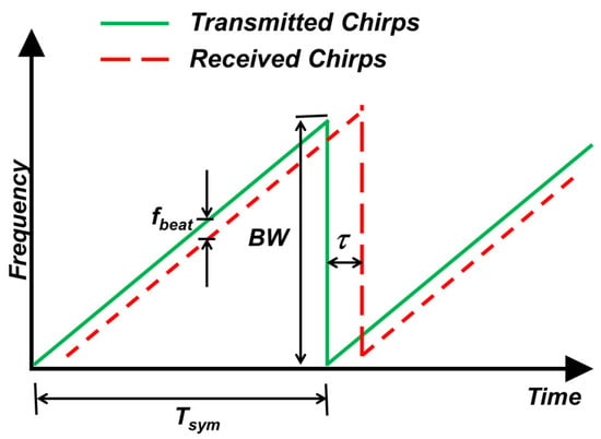
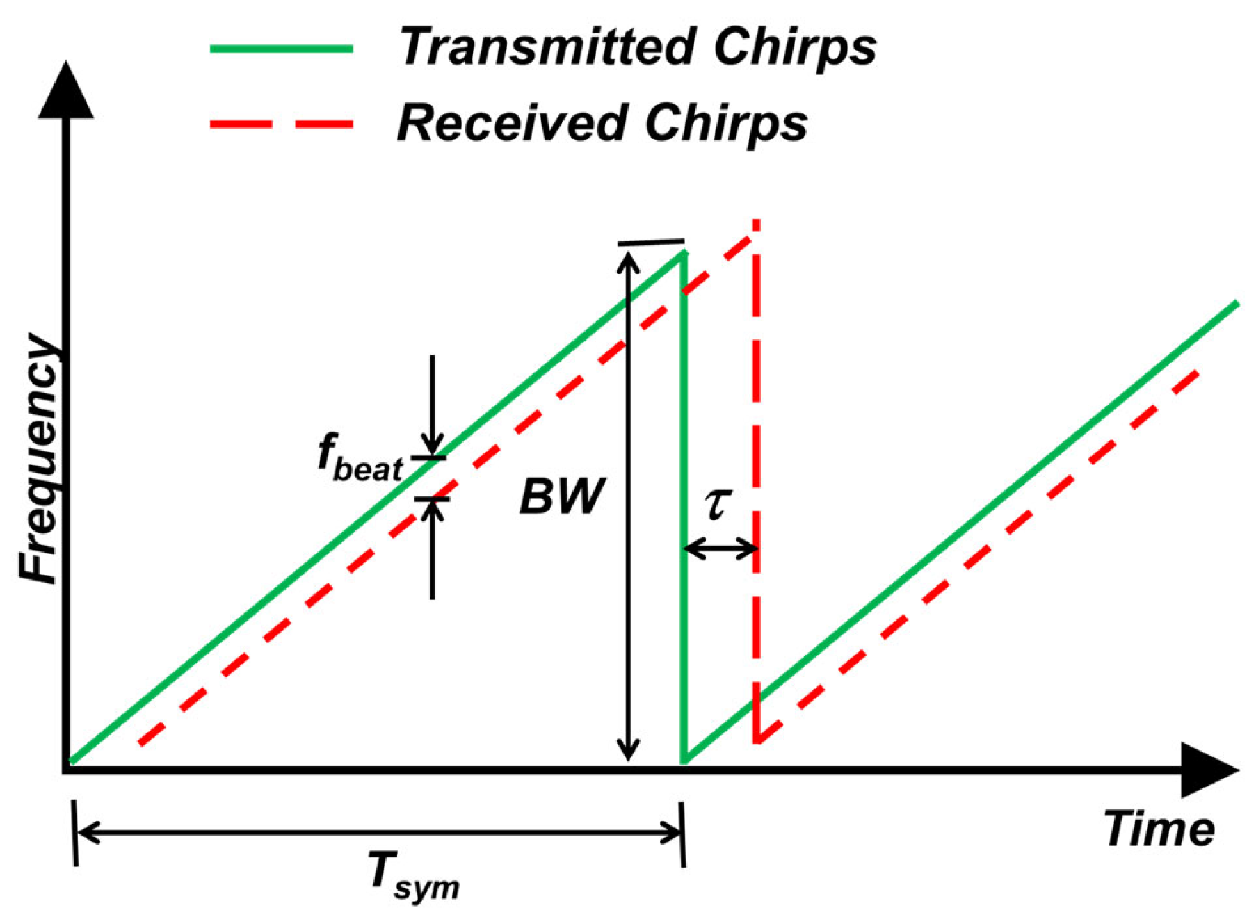
Frequency Modulated Continuous Wave (FMCW) radar uses sawtooth modulation or linear frequency modulation to obtain the speed and distance of an object [39]. The received signal at the radar is a shifted version of the transmitted signal, due to the propagation delay to reach the destination and return. The beat frequency () consists of the difference between the transmitted and received frequencies [39]. Figure 1 illustrates the principle of operation of the FMCW radar, where the received signal at the radar (dashed red line) has a time (τ) and frequency () offset with respect to the transmitted signal (solid green line). and represent the bandwidth and duration of each chirp, respectively.
Figure 1.
Operating principle of the FMCW radar. Adapted from [39].
If a sawtooth modulation, with a bandwidth , chirp time is used to detect a target at a distance , the beat frequency [40] is given by (1):
where is the propagation velocity of the electromagnetic wave. Note that , , , and are known. Furthermore, the radar system uses the Fast Fourier Transform (FFT) to obtain a peak at a specific frequency that denotes the presence of an object at a certain distance [39]. Hence, the system computes , which, in turn, allows for estimation of using Equation (1).
All digital communication systems employ a transmitter baseband stage that generates discrete-time signals [41] by sampling. In such instances, the system can determine the number of samples as follows [42]:
In practical implementations, once the LoRa RF signal is down-converted to baseband, selecting a sampling frequency ≥ 2 satisfies the Nyquist criterion for accurate digitization [41]. Such a choice ensures adequate spectral separation essential for Digital to Analog Converter (DAC) filtering and maintaining signal integrity within the bandwidth .
4. One-Way LoRa Chirp Distance Estimation Method
The proposed method uses LoRa modulation and its similarities with radar to detect the delay and determine the distance to the transmitting node. Note that a radar uses the transmitted signal and the corresponding reflected signal from the object. On the other hand, a LoRa receiver detects only one signal with a pre-established structure. The proposed method takes advantage of this situation to compute the distance from the transmitter using one-way estimation.
4.1. Method Description
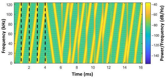
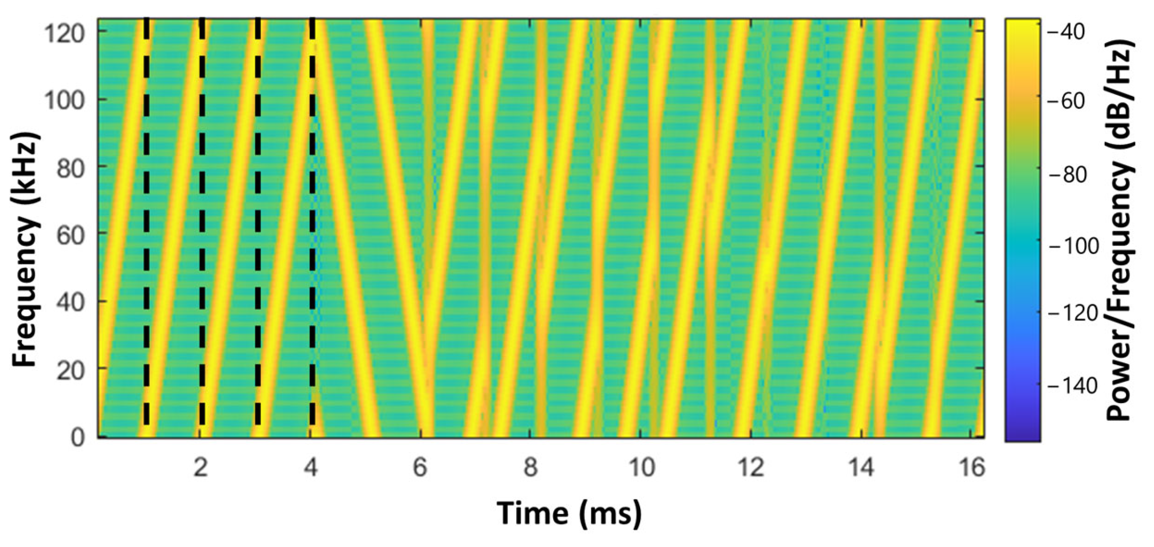
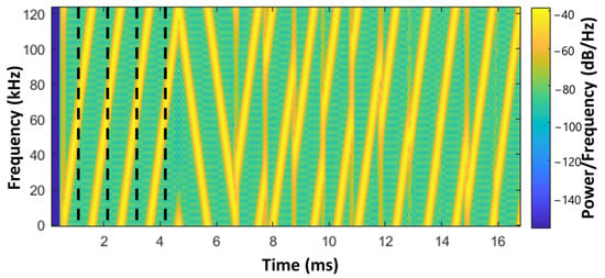
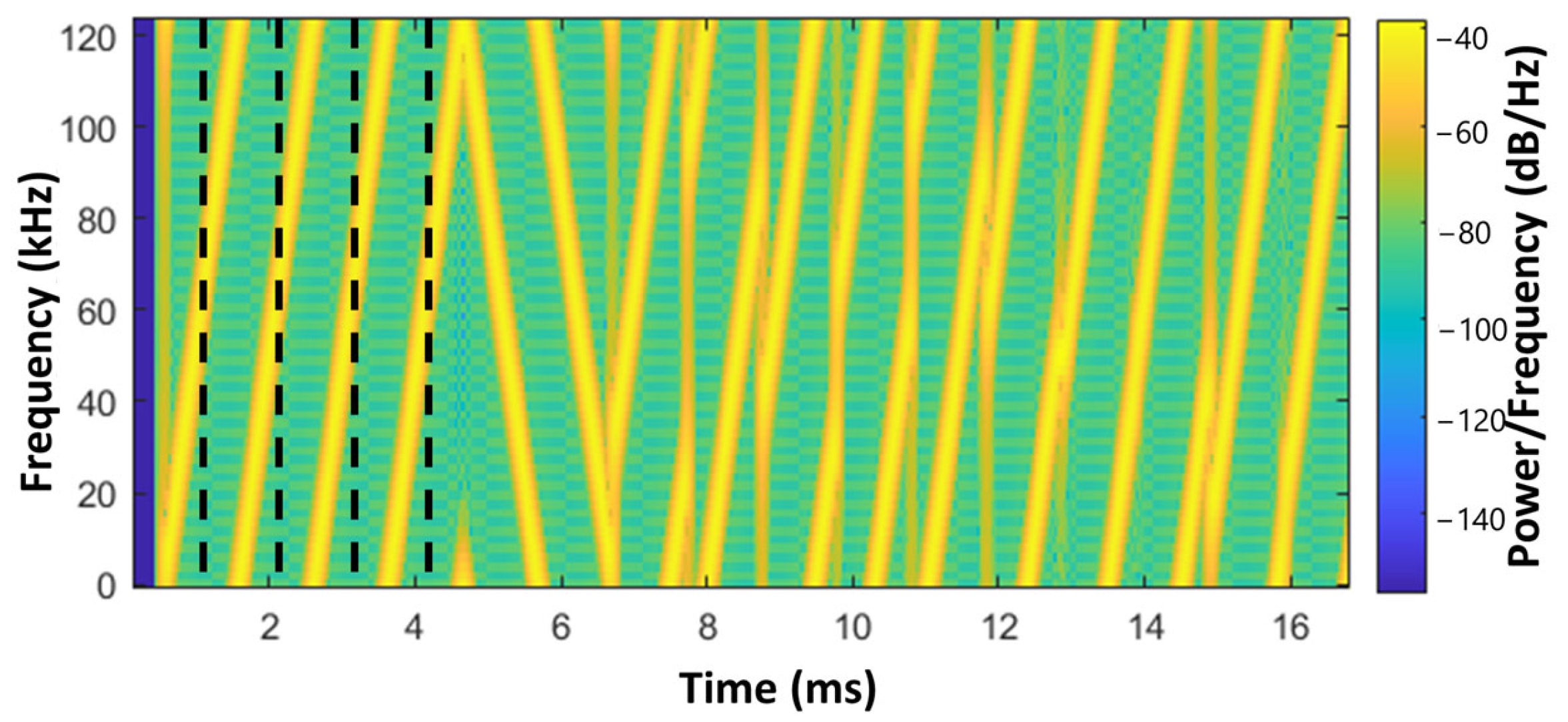
The method uses the concepts from Figure 1 but assumes that the transmitted chirps are LoRa signals. Figure 2 shows a transmitted LoRa frame with a preamble of four upchirps, two synchronization downchirps (delimiters), and ten information chirps. The method focuses on the preamble; thus, the figure shows dotted lines that demarcate the time interval of each upchirp. Note that the dotted lines intersect the upchirps at the zero frequency. Hence, the expected symbol value in each one is zero (0).
Figure 2.
Spectrogram of one transmitted frame. The dashed lines demarcate the time intervals of each upchirp in the preamble.
These signals arrive at the LoRa receiver with a one-way delay corresponding to half the value of τ, as shown in Figure 1. Our method name reflects this situation. Figure 3 shows this delay with a blue vertical strip. The dashed lines show the time interval of each chirp. However, these lines intersect the chirps at frequencies different from zero; therefore, they represent different symbols than the expected upchirps.
Figure 3.
Spectrogram of the received frame. The dashed lines show the time intervals of each symbol in the preamble. The blue vertical strip represents the propagation delay of the signal.
If the receiver detects a value different from zero, there is a shift related to the transmission delay. The proposed method computes this delay in the number of samples () using Equation (3):
where indicates the Spreading Factor, is the second symbol of the preamble, and γ is the sampling factor or bandwidth multiplier factor that determines the sampling frequency (). Hence, = γ .
Note that the method could use the first symbol in the preamble; however, receiver characteristics can cause variations in the signal strength of the first symbol, reducing detection accuracy [43]. Therefore, to improve time estimation, the method uses the second symbol instead, because all preamble symbols are the same and have the same link delay.
Then, the method determines the distance from the delay detected in the received message. Equation (4) relates the detected delay to the distance in meters, where corresponds to the speed of light, . This equation shows that the distance estimation depends upon sampling frequency.
Thus, the proposed method defines the minimum distance resolution as the minimum detectable distance with the time used for one sample, corresponding to 1/ in seconds. Employing the speed of light, the minimum distance occurs with:
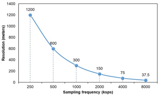
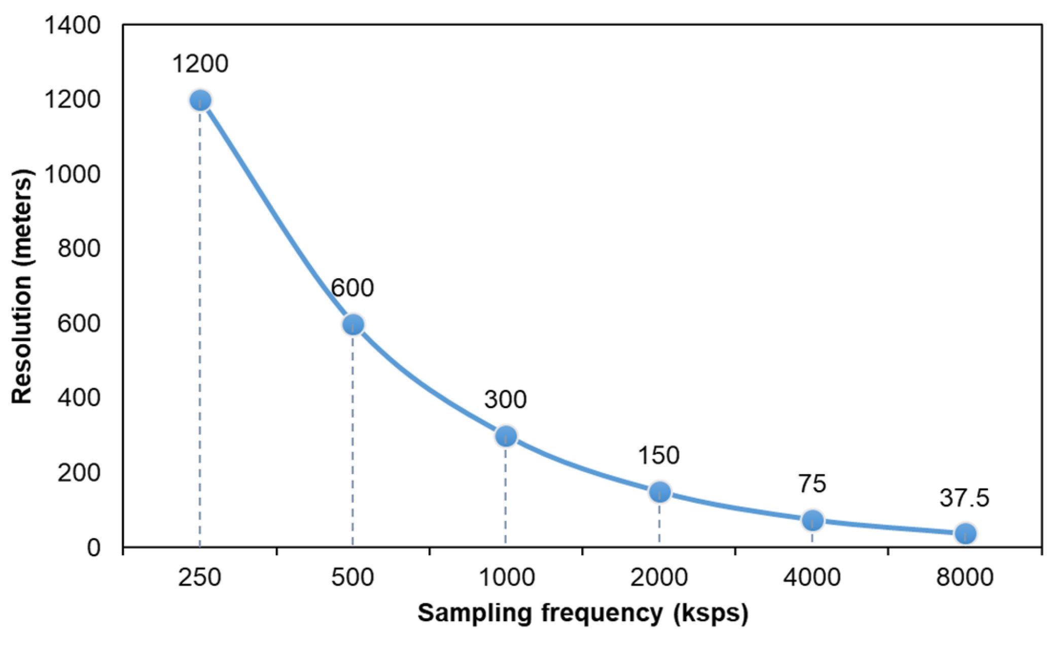
Figure 4 shows the analytical relationship between and the resolution using Equation (5), varying the values of and keeping as . Hence, the resolution decreases when increasing .
Figure 4.
Distance resolution and sampling frequency.
Note that the minimum value in Figure 4 is smaller than the error obtained in [27], 38.7 m. Hence, to improve this error, the proposed method should use more than 8 Mega samples per second (Msps). Although the signal bandwidth remains unchanged, increasing the sampling rate enhances the time resolution of the received signal. This finer temporal granularity reduces quantization noise [44] in time-delay estimation and enables more accurate determination of time-based parameters.
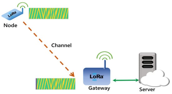
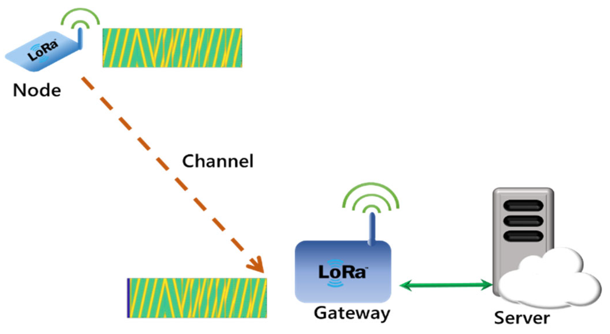
As an illustration, Figure 5 shows the method in a simple system, consisting of a LoRa node connected to one GW. The GW communicates with a server that processes the received information. The transmitted CSS-LoRa signal arrives at the GW with a certain delay, according to the distance between them. The proposed method calculates the distance by detecting the LoRa frame header and identifying the delay. Thus, the method only needs to process the signal at the GW. The node is not synchronized with the GW, and there are no time stamps or comparisons with the information received at other nodes.
Figure 5.
Simplified diagram of the proposed system. The dashed line shows the wireless link, the solid line shows a bidirectional connection.
4.2. Experimental Setup
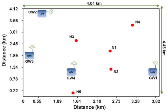
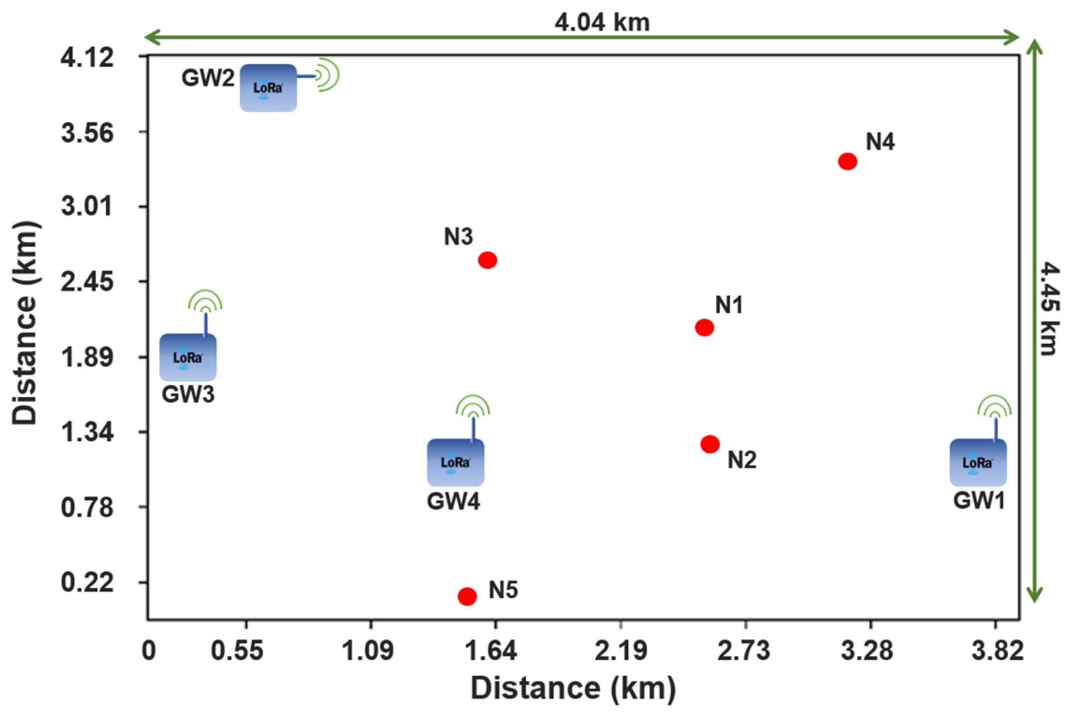
This section provides a detailed description of the simulation scenario in a semi-urban outdoor environment to verify the method’s performance under conditions similar to a smart city. The tests use five nodes and four GWs at diverse locations across a city within an area of approximately 18 km2, to verify the ranging performance through different distances. The GWs are not synchronized, do not exchange information regarding the nodes, and do not know the propagation model. The GWs receive signals from each node and compute the distance using the proposed chirp-based method. Unless otherwise specified, the simulator runs 200 tests using the locations in Figure 6 with LoRa configurations explained in the following section. The LoRa frames include four preamble symbols, two downchirps, and 10 payload symbols, as shown in Figure 2 and Figure 3. All calculations use the absolute value of the ranging error. This paper uses MATLAB as the simulation tool for modeling the test scenario and a LoRa baseband communication system [45]. The system uses a complex envelope method and creates frame by generating the chirps corresponding to a preamble, a delimiter and random data as payload. Then, the system transmits the frame through a channel to a receiver. This receiver multiplies the signal by a downchirp, then applies the Fast Fourier Transform (FFT) and obtains the peaks corresponding to the values of each symbol in the frame [45].
Figure 6.
Distribution of the test scenario, nodes (red dots), and GWs (blue rectangles). The arrows show the dimensions of the test area.
Figure 6 illustrates the layout of the test scenario, where the red dots identify the nodes (Ni) and the squares represent the GWs (GWi). Table 2 summarizes the distances between the nodes and GWs.
Table 2.
Distances between nodes and gateways (km).
All nodes use 14 dBm transmission power at the 900 MHz band. To emulate what occurs in an actual situation, the simulation uses the Okumura–Hata propagation model for suburban areas at 902.3 MHz. Based on this model, each GW receives the average power corresponding to each node-GW link. Equations (6)–(8) describe the Okumura–Hata model [46].
where denotes the path loss in an urban environment; is the loss model with correction for suburban areas; corresponds to the correction factor for the height of the receiving antenna; is the transmission frequency; is the height of the transmitting antenna; is the height of the receiving antenna; and is the distance [46].
The model employs a Monte Carlo simulation, where the transmitted data are randomly generated, and the channel introduces stochastic effects on the signal. The model uses a Rayleigh distribution that represents an NLOS environment, including moving nodes and obstacles. The simulations use 83.3 Hz as a Doppler shift, corresponding to a device transmitting at 900 MHz and a relative speed of 100 km/h [47]. Furthermore, the model uses the basic MATLAB multipath model with a maximum delay spread of 15 microseconds to emulate channels of several kilometers [48].
This setup provides the characteristic randomness of a radio channel in a real environment [49], causing variability in the RSSI values and propagation times for each link. Thus, the model is consistent with the effects of fast fading and channel multipath, which, under critical conditions, represent the worst-case scenario for any communication system in a smart city, similar to that presented in [50]. Table 3 summarizes all the factors and levels employed in the experimental design.
Table 3.
Distance Estimation Experimental Design.
A LoRa system with a 125 kHz and 7 obtains the maximum data rate and the minimum symbol duration, creating a worst-case scenario for the proposed one-way method. Hence, the results are expected to show the maximum distance error. Moreover, tests do not include CRC to maximize the effect of errors in transmission. Additionally, a 125 kHz bandwidth is the minimum permitted by LoRa. Thus, using as multiples of 125 kHz allows analysis from the simplest case (small ) to larger values, which can be applied to 250 and 500 kHz. Moreover, the 83.3 Hz Doppler shift corresponds to a coherence time of 6 milliseconds [47], and the symbol duration in LoRa with the mentioned configuration is 1 millisecond. Therefore, the channel for 7 can be considered as time invariant. Furthermore, the maximum delay spread is 15 microseconds, which is three orders of magnitude smaller than the symbol duration. Thus, the frequency response of the channel is approximately flat. These results are consistent with those of [50] and confirm the robustness of LoRa under these specific propagation conditions.
5. Results and Discussion
This section presents the simulation results to show the performance of the one-way method under worst-case scenario conditions. Additionally, the method was tested with the minimum and maximum values of and allowed by LoRa to recommend hardware configurations for decreasing the ranging error.
5.1. Distance Estimation for Worst-Case Scenario
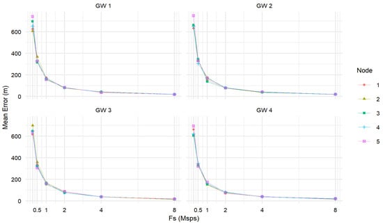
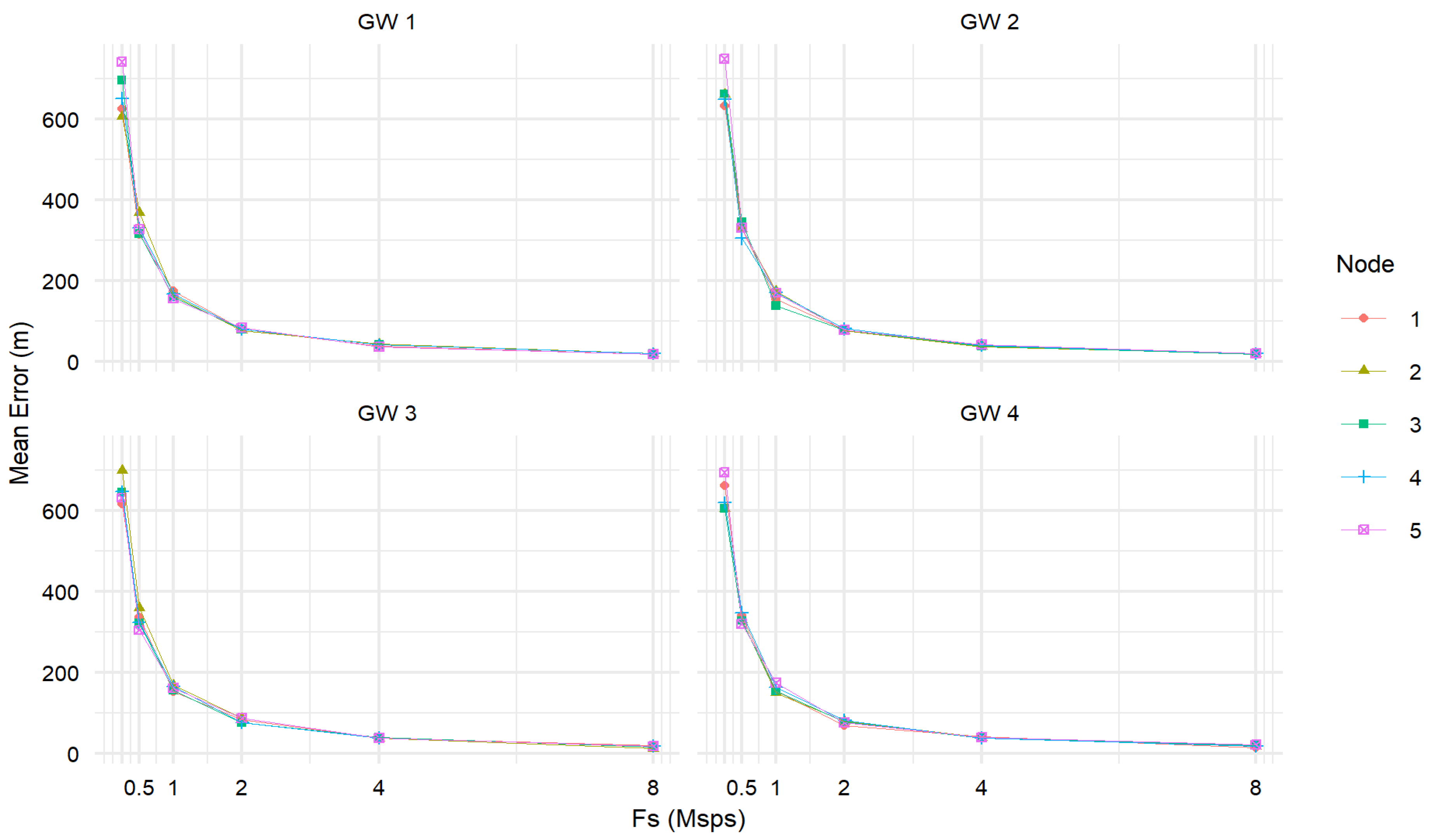
These experiments use the scenario in Figure 6 to find the distance from each node computed at each gateway for every sampling rate in Table 3. Figure 7 shows the mean error in meters obtained from the distance estimation for each node at each GW. values range from 250 ksps to 8 Msps. This behavior is consistent with Figure 4, where a larger value decreases the mean error in meters. There are no statistical differences for nodes using the same value.
Figure 7.
Mean ranging error in meters for each node and GW using different sampling rates.
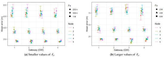
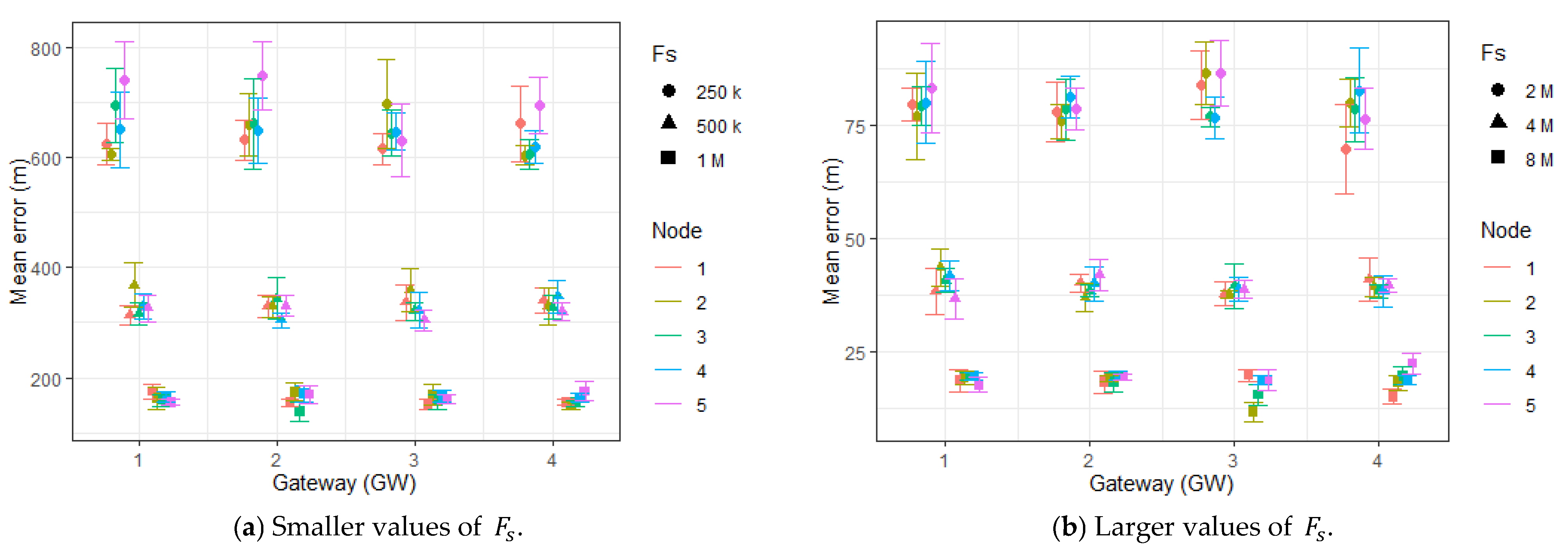
Figure 8 shows the mean error for each GW, Node and value, including 95% confidence intervals. The figure allows a detailed analysis, showing no statistical differences when comparing different GW. Hence, GW’s position in the test area did not affect the results. Again, increasing the value decreases mean error with no statistical difference for cases using the same or GW. Furthermore, Figure 8a illustrates the maximum error values obtained for each value, as follows: 820 m with 250 ksps (circle), 420 m with 500 ksps (triangle), and less than 200 m for 1 Msps (square). These ranging errors may not be useful for IoT applications. However, Figure 8b shows the error obtained with larger values, 90 m with 2 Msps (circle), 48 m with 4 Msps (triangle), and 25 m with 8 Msps (square).
Figure 8.
Mean ranging error for all GWs, nodes, and values with 95% confidence intervals (a) for 250 ksps, 500 ksps, and 1 Msps. (b) for 2, 4, and 8 Msps.
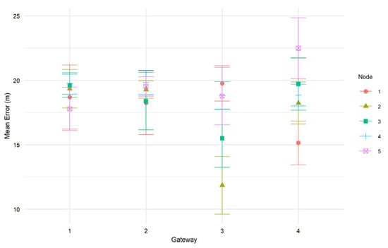
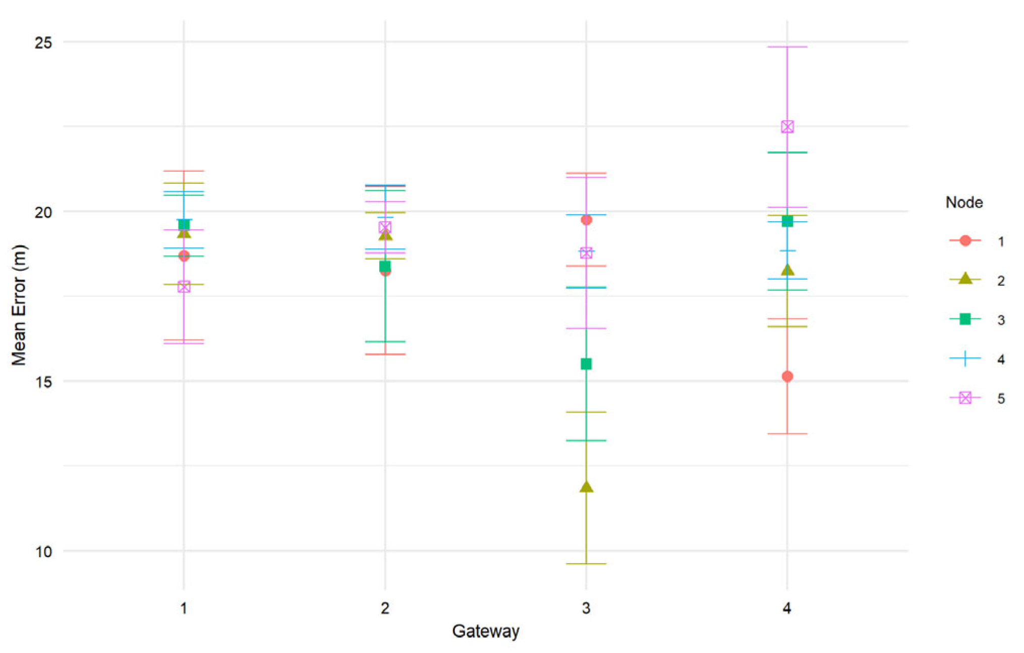
Figure 9 shows the mean ranging error for 8 Msps to clarify the results obtained with the maximum value of .
Figure 9.
Mean error values with confidence intervals for all GWs and nodes using 8 Msps.
According to Figure 9, the mean error at 8 Msps is less than 25 m, illustrating the accuracy of the proposed method at larger sampling rates. Moreover, compared to the related work, three papers exhibit test distances and error values comparable to this study: 46 m [26], 38.7 m [27], and 23 m [28]. However, the first study requires communication in both directions, thus requiring modification of the node configuration [22]. The second comparable study requires synchronization among the GWs [27]. The third study requires a fixed node to synchronize GWs with trilateration [28]. Furthermore, the Seirios method is the closest to the proposed method in terms of chirp signal utilization [30]. However, the working area of Seirios is significantly smaller (100 m × 60 m), and it requires two antennas per gateway to achieve trilateration.
In summary, the proposed chirp-based ranging method achieves errors comparable to those of related studies without modifying the design of the transmitters and with no additional requirements, such as time stamps, antennas, or nodes.
5.2. Recommendation of LoRa Configurations to Decrease Ranging Error
Results presented in Section 5.1 correspond to the expected worst-case scenario for the proposed ranging method. Moreover, this section studies the average ranging error using the same scenario but modifying three factors that can be configured in a LoRa system. The goal is to find LoRa hardware configurations that can be useful for researchers and practitioners. Thus, the experiments use the minimum and maximum values allowed by the LoRa standard [6], according to Table 4:
Table 4.
System Configuration Experimental Design.
This analysis includes the results from Node 1. The behavior of all other nodes was consistent with this one.
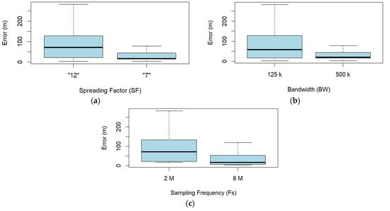
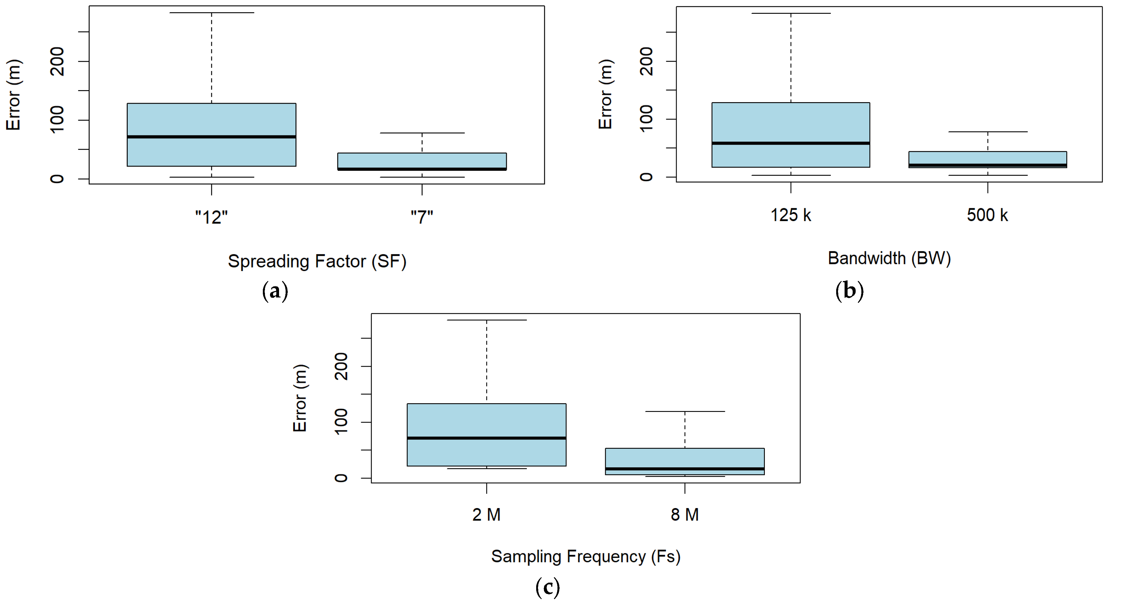
Figure 10 shows the boxplots of the ranging error for , , and . According to this figure, the ranging error decreases when decreases and and increase. The behavior is expected because all these conditions allow for a larger number of samples and are expected to decrease the ranging resolution, as shown in Figure 4, along with the ranging error. Thus, analyzing the results individually, as in Figure 10, one can think that the configuration for a LoRa device for minimizing error is 7, 500 kHz, and 8 Msps.
Figure 10.
Ranging error according to (a) , (b) , and (c) .
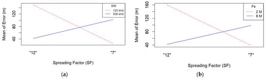
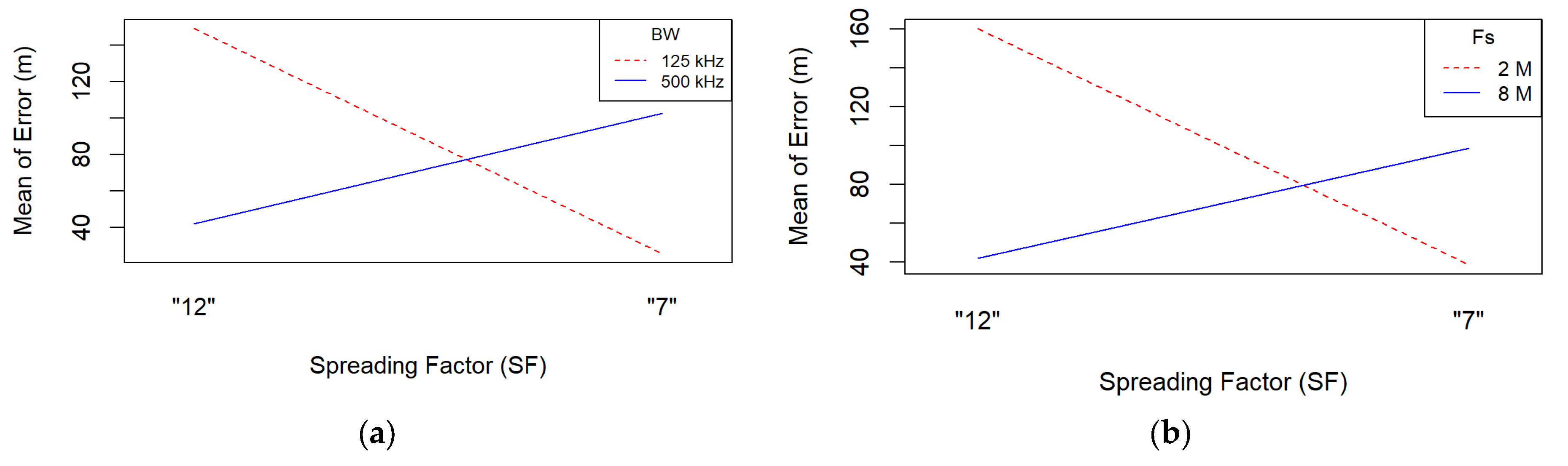
However, the experimental design described in Table 2 allows to determine the interaction of factors. Thus, when analyzing the effect of all factors combined, the situation is different. Figure 11a shows the interactions between and . According to the figure, employing 125 kHz and SF 7 reduces the mean ranging error. The opposite effect is observed when using a 500 kHz . Furthermore, Figure 11b shows that using 2 Msps requires 7 to decrease error. On the other hand, employing 8 Msps requires SF 12 to decrease ranging error.
Figure 11.
Interaction plots (a) between and and (b) between and .
Thus, the results in Figure 11 show that using the largest and does not always reduce the mean error, as suggested by Figure 10. In fact, Figure 11 allows us to recommend two LoRa configurations to decrease the mean ranging error: a configuration of 2 Msps , 125 kHz , and 7 can be used with limited hardware devices. Additionally, if the hardware allows 8 Msps, the configuration for small distance error includes 12 and 500 kHz . This information is important for researchers and designers because smaller values are easier to obtain in hardware, providing a good tradeoff between hardware requirements and ranging error.
6. Conclusions
The paper presented a one-way method for ranging that involves a LoRa transmitter and a receiver capable of detecting the link delay using demodulation of the preamble. The method exploits the LoRa waveform to obtain the distance from the same signals transmitted during regular communications without using additional hardware, previous knowledge of the propagation model, and synchronization between devices.
The simulation results show that the system can measure the link distance with a mean error of 25 m for a semi-urban, 18 km2, NLOS environment with a Rayleigh channel, which emulates a worst-case scenario for a smart city. The results show that the distance resolution of the system (i.e., the minimum distance detectable by each sample) decreases when the sampling frequency () increases. More specifically, increasing in powers of two decreases the distance resolution by half. Furthermore, our method, working at 8 Msps, obtains the best distance error, smaller than other methods proposed in the literature. Moreover, our results show that using the maximum values for and does not always decrease ranging error. As a matter of fact, the results show two different configurations that decrease ranging error: one with 2 Msps, 125 kHz and 7, and the other with 8 Msps, 500 kHz and 12.
The proposed one-way chirp distance measurement method is useful for non-GPS LoRa IoT applications in smart cities. These results are helpful for researchers and LoRa network designers related to the IoT ecosystem.
Future work should study the effect of variables such as preamble length, diverse propagation models, delay spread values, coherence bandwidth, coherence time, Carrier Frequency Offset (CFO) or Sample Frequency Offset (SFO) on ranging error rates. Future work should also implement the method in hardware devices and test the performance under interference conditions similar to those expected in smart cities. Moreover, the method should also be tested in indoor conditions over smaller distances, to verify the usefulness for office, buildings and industrial applications.
Author Contributions
Conceptualization, Data Curation, Formal Analysis, Investigation, and Writing—original draft, L.E.M.; Methodology, Data Curation, Formal Analysis, Supervision, and Writing—review and editing, M.C.; Methodology, Validation, Visualization, and Writing—review and editing, J.E.C.-B. All authors have read and agreed to the published version of the manuscript.
Funding
This research received no external funding.
Data Availability Statement
All data are included within the article.
Acknowledgments
The work of Luz E. Márquez was supported by the Institución Universitaria de Barranquilla. The work of Maria Calle was supported by the Universidad del Norte. The work of John E. Candelo-Becerra was supported by the Universidad Nacional de Colombia, Sede Medellín.
Conflicts of Interest
The authors declare no conflicts of interest.
References
- Li, L. Node Location Method of Ecological Environment Monitoring Network Based on Zigbee. Discret. Dyn. Nat. Soc. 2022, 2022, 5854569. [Google Scholar] [CrossRef] [Scilit]
- Islam, K.Z.; Murray, D.; Diepeveen, D.; Jones, M.G.K.; Sohel, F. LoRa-based outdoor localization and tracking using unsupervised symbolization. Internet Things 2024, 25, 101016. [Google Scholar] [CrossRef] [Scilit]
- Aernouts, M.; BniLam, N.; Berkvens, R.; Weyn, M. TDAoA: A combination of TDoA and AoA localization with LoRaWAN. Internet Things 2020, 11, 100236. [Google Scholar] [CrossRef] [Scilit]
- Shurrab, M.; Mizouni, R.; Singh, S.; Otrok, H. Reinforcement learning framework for UAV-based target localization applications. Internet Things 2023, 23, 100867. [Google Scholar] [CrossRef] [Scilit]
- Porselvi, T.; Saranraj, A.K.; Rikthish, B.P.; Prabakaran, M.; Priya, S.; Hemalatha. Industrial Automation Using IoT. In Proceedings of the 2023 Intelligent Computing and Control for Engineering and Business Systems (ICCEBS), Chennai, India, 14–15 December 2023; pp. 1–5. [Google Scholar] [CrossRef] [Scilit]
- Marquez, L.E.; Calle, M. Understanding LoRa-Based Localization: Foundations and Challenges. IEEE Internet Things J. 2023, 10, 11185–11198. [Google Scholar] [CrossRef] [Scilit]
- Janssen, T.; Berkvens, R.; Weyn, M. Benchmarking RSS-based localization algorithms with LoRaWAN. Internet Things 2020, 11, 100235. [Google Scholar] [CrossRef] [Scilit]
- Lee, S.; Seok, H.-W.; Lee, K.; In, H.P. B-GPS: Blockchain-Based Global Positioning System for Improved Data Integrity and Reliability. ISPRS Int. J. Geoinf. 2022, 11, 186. [Google Scholar] [CrossRef] [Scilit]
- Hoffmann, M.; Kryszkiewicz, P.; Koudouridis, G.P. Modeling of Real Time Kinematics localization error for use in 5G networks. EURASIP J. Wirel. Commun. Netw. 2020, 2020, 31. [Google Scholar] [CrossRef] [Scilit]
- Shit, R.C.; Sharma, S.; Watters, P.; Yelamarthi, K.; Pradhan, B.; Davison, R.; Morgan, G.; Puthal, D. Privacy-preserving cooperative localization in vehicular edge computing infrastructure. Concurr. Comput. 2022, 34, e5827. [Google Scholar] [CrossRef] [Scilit]
- Bouras, C.; Gkamas, A.; Salgado, S.A.K. Energy efficient mechanism for LoRa networks. Internet Things 2021, 13, 100360. [Google Scholar] [CrossRef] [Scilit]
- Khedr, A.M.; Aziz, A.; Osamy, W. Diverse Localization Techniques in Wireless Sensor Networks: A Review. In Lecture Notes in Computer Science; Including Subseries Lecture Notes in Artificial Intelligence and Lecture Notes in Bioinformatics LNCS; Springer Science and Business Media Deutschland GmbH: Berlin/Heidelberg, Germany, 2024; Volume 14543, pp. 363–382. [Google Scholar] [CrossRef] [Scilit]
- Gu, C.; Jiang, L.; Tan, R. LoRa-Based Localization: Opportunities and Challenges. In Proceedings of the 2019 International Conference on Embedded Wireless Systems and Networks; Junction Publishing: Beijing, China, 2019; pp. 413–418. [Google Scholar]
- Li, B.; Xu, Y.; Liu, Y.; Shi, Z. LoRaWAPS: A Wide-Area Positioning System Based on LoRa Mesh. Appl. Sci. 2023, 13, 9501. [Google Scholar] [CrossRef] [Scilit]
- Hu, K.; Chen, Y.; He, S.; Shi, Z.; Chen, J.; Tao, Z. ILoc: A low-cost low-power outdoor localization system for internet of things. In Proceedings of the 2019 IEEE Global Communications Conference, GLOBECOM, Waikoloa, HI, USA, 9–13 December 2019; pp. 1–6. [Google Scholar] [CrossRef] [Scilit]
- Savazzi, P.; Goldoni, E.; Vizziello, A.; Favalli, L.; Gamba, P. A Wiener-Based RSSI Localization Algorithm Exploiting Modulation Diversity in LoRa Networks. IEEE Sens. J. 2019, 19, 12381–12388. [Google Scholar] [CrossRef] [Scilit]
- Merhej, D.; Ahriz, I.; Zerioul, L.; Garcia, S.; Terré, M. Joint RSS and Ranging Fingerprint for LoRa Indoor Localization. In Proceedings of the 2024 IEEE Wireless Communications and Networking Conference (WCNC), Dubai, United Arab Emirates, 21–24 April 2024; pp. 1–6. [Google Scholar] [CrossRef] [Scilit]
- Vo, H.; Nguyen, V.H.L.; Tran, V.L.; Ferrero, F.; Lee, F.-Y.; Tsai, M.-H. Advance Path Loss Model for Distance Estimation Using LoRaWAN Network’s Received Signal Strength Indicator (RSSI). IEEE Access 2024, 12, 83205–83216. [Google Scholar] [CrossRef] [Scilit]
- Khriji, S.; Kavali, M.; Kanoun, O. A Hybrid Filter for Accurate RSSI-Based LoRa Distance Estimation Systems in IoT Applications. In Proceedings of the 2024 21st International Multi-Conference on Systems, Signals and Devices, SSD, Erbil, Iraq, 22–25 April 2024; pp. 304–308. [Google Scholar] [CrossRef] [Scilit]
- Wang, C.-Y.; Zhong, M.-Z.; Wang, S.-C.; Chang, R.C.-H.; Wen, C.-Y. LoRa-Based Hierarchical Network Architecture for IoT Indoor Positioning Applications. In Proceedings of the 2023 International Conference on Consumer Electronics-Taiwan (ICCE-Taiwan), PingTung, Taiwan, 17–19 July 2023; pp. 147–148. [Google Scholar] [CrossRef] [Scilit]
- Qiang, L.; Ying, M.; Xiujun, B.; Xiangning, L.; Yan, L.; Chunlei, H. Research on Localization Techniques in Occluded Environments Based on Lora Signals. In Proceedings of the 2024 IEEE 14th International Conference on Electronics Information and Emergency Communication (ICEIEC), Beijing, China, 24–25 May 2024; pp. 205–208. [Google Scholar] [CrossRef] [Scilit]
- Muller, P.; Stoll, H.; Sarperi, L.; Schupbach, C. Outdoor Ranging and Positioning based on LoRa Modulation. In Proceedings of the 2021 International Conference on Localization and GNSS, ICL-GNSS, Tampere, Finland, 1–3 June 2021; pp. 1–6. [Google Scholar] [CrossRef] [Scilit]
- Tobbal, A.; Bengherbia, B.; Bouziani, A.; Cherifi, Y. Experimental Study of a LoRa Based Wireless Sensor Network for Low Power Localization in an Outdoor Environment. In Proceedings of the 2023 2nd International Conference on Electronics, Energy and Measurement (IC2EM), Medea, Algeria, 28–29 November 2023; pp. 1–6. [Google Scholar] [CrossRef] [Scilit]
- Purohit, J.; Wang, X.; Mao, S.; Sun, X.; Yang, C. Fingerprinting-based Indoor and Outdoor Localization with LoRa and Deep Learning. In Proceedings of the GLOBECOM 2020-2020 IEEE Global Communications Conference, Taipei, Taiwan, 7–11 December 2020; pp. 1–6. [Google Scholar] [CrossRef] [Scilit]
- Makino, I.; Miki, N. Open-Source Hardware-Based Three-Dimensional Positioning Device for Indoor Measurement and Positioning. IEEE Access 2023, 11, 11254–11267. [Google Scholar] [CrossRef] [Scilit]
- Anjum, M.; Khan, M.A.; Hassan, S.A.; Mahmood, A.; Gidlund, M. Analysis of RSSI Fingerprinting in LoRa Networks. In Proceedings of the 2019 15th International Wireless Communications & Mobile Computing Conference (IWCMC), Tangier, Morocco, 24–28 June 2019; pp. 1178–1183. [Google Scholar] [CrossRef] [Scilit]
- Ghany, A.A.; Uguen, B.; Lemur, D. A Parametric TDoA Technique in the IoT Localization Context. In Proceedings of the 2019 16th Workshop on Positioning, Navigation and Communications (WPNC), Bremen, Germany, 23–24 October 2019; pp. 1–6. [Google Scholar] [CrossRef] [Scilit]
- Muppala, R.; Navnit, A.; Devendra, D.; Matera, E.R.; Accettura, N.; Hussain, A.M. Feasibility of Standalone TDoA-based Localization Using LoRaWAN. In Proceedings of the 2021 International Conference on Localization and GNSS (ICL-GNSS), Tampere, Finland, 1–3 June 2021; pp. 1–7. [Google Scholar] [CrossRef] [Scilit]
- Song, Z.; Tong, S.; Wang, J. LoSense: Integrated Long-Range Sensing and Communication with LoRa Signals. In Proceedings of the 2023 IEEE 31st International Conference on Network Protocols (ICNP), Reykjavik, Iceland, 10–13 October 2023; pp. 1–11. [Google Scholar] [CrossRef] [Scilit]
- Liu, J.; Gao, J.; Jha, S.; Hu, W. Seirios: Leveraging multiple channels for LoRaWAN indoor and outdoor localization. In Proceedings of the 27th Annual International Conference on Mobile Computing and Networking; ACM: New York, NY, USA, 2021; pp. 656–669. [Google Scholar] [CrossRef] [Scilit]
- Povalac, A.; Kral, J.; Arthaber, H.; Kolar, O.; Novak, M. Exploring LoRaWAN Traffic: In-Depth Analysis of IoT Network Communications. Sensors 2023, 23, 7333. [Google Scholar] [CrossRef] [Scilit]
- Azim, A.W.; Shubair, R.; Chafii, M. Chirp Spread Spectrum-Based Waveform Design and Detection Mechanisms for LPWAN-Based IoT: A Survey. IEEE Access 2024, 12, 24949–25017. [Google Scholar] [CrossRef] [Scilit]
- Kufakunesu, R.; Hancke, G.P.; Abu-Mahfouz, A.M. Collision Avoidance Adaptive Data Rate Algorithm for LoRaWAN. Future Internet 2024, 16, 380. [Google Scholar] [CrossRef] [Scilit]
- Steinmetz, F.; Renner, C. Practical Evaluation of Differential Frequency Shift Chirp Modulation for Acoustic Underwater Communication. In Proceedings of the 17th International Conference on Underwater Networks & Systems; ACM: New York, NY, USA, 2023; pp. 1–8. [Google Scholar] [CrossRef] [Scilit]
- Mekki, K.; Bajic, E.; Chaxel, F.; Meyer, F. A comparative study of LPWAN technologies for large-scale IoT deployment. ICT Express 2019, 5, 1–7. [Google Scholar] [CrossRef] [Scilit]
- Xu, Z.; Tong, S.; Xie, P.; Wang, J. From Demodulation to Decoding: Toward Complete LoRa PHY Understanding and Implementation. ACM Trans. Sens. Netw. 2022, 18, 1–27. [Google Scholar] [CrossRef] [Scilit]
- Maleki, A.; Nguyen, H.H.; Bedeer, E.; Barton, R. A Tutorial on Chirp Spread Spectrum Modulation for LoRaWAN: Basics and Key Advances. IEEE Open J. Commun. Soc. 2024, 5, 4578–4612. [Google Scholar] [CrossRef] [Scilit]
- Skolnik, M. An Introduction and Overview of Radar. In Radar-Handbook; Skolkik, M., Ed.; McGraw-Hill: New York, NY, USA, 1990; Chapter 1; Available online: https://ftp.idu.ac.id/wp-content/uploads/ebook/tdg/ADNVANCED%20MILITARY%20PLATFORM%20DESIGN/Radar%20Handbook.pdf (accessed on 26 January 2026).
- Long, N.; Wang, K.; Cheng, R.; Yang, K.; Hu, W.; Bai, J. Assisting the visually impaired: Multitarget warning through millimeter wave radar and RGB-depth sensors. J. Electron. Imaging 2019, 28, 1. [Google Scholar] [CrossRef] [Scilit]
- Hao, Y.; Song, P.; Wang, X.; Pan, Z. A Spectrum Correction Algorithm Based on Beat Signal of FMCW Laser Ranging System. Sensors 2021, 21, 5057. [Google Scholar] [CrossRef] [Scilit] [PubMed]
- Pasolini, G. On the LoRa Chirp Spread Spectrum Modulation: Signal Properties and Their Impact on Transmitter and Receiver Architectures. IEEE Trans. Wirel. Commun. 2022, 21, 357–369. [Google Scholar] [CrossRef] [Scilit]
- Thomas, A.; Eldhose, N.V. Performance Evaluation of Chirp Spread Spectrum as used in LoRa Physical Layer. In Proceedings of the 2019 IEEE International Conference on System, Computation, Automation and Networking (ICSCAN), Pondicherry, India, 29–30 March 2019; pp. 1–6. [Google Scholar] [CrossRef] [Scilit]
- Guo, D.; Gu, C.; Jiang, L.; Luo, W.; Tan, R. ILLOC. Proc. ACM Interact. Mob. Wearable Ubiquitous Technol. 2022, 6, 1–26. [Google Scholar] [CrossRef] [Scilit]
- Marquez, L.E.; Calle, M. Improving LoRa BER performance by increasing sampling rate. In Proceedings of the 2024 IEEE Colombian Conference on Communications and Computing, COLCOM, Barranquilla, Colombia, 21–23 August 2024. [Google Scholar] [CrossRef] [Scilit]
- Marquez, L.E.; Calle, M.; Velez, J.C. Modeling LoRa: A Complex Envelope Approach. In Proceedings of the 2020 International Symposium on Networks, Computers and Communications (ISNCC), Montreal, QC, Canada, 20–22 October 2020; pp. 1–6. [Google Scholar] [CrossRef] [Scilit]
- Bouchemha, A.; Djellab, H.; Nait-Hamoud, M.C. Analysis and optimization of 4G/LTE network pathloss using Particles Swarm Optimization algorithm. Int. J. Electr. Electron. Res. 2024, 12, 557–566. [Google Scholar] [CrossRef] [Scilit]
- Haykin, S.; Moher, M. Modern Wireless Communications; Pearson Education: Upper Saddle River, NJ, USA, 2005. [Google Scholar]
- MathWorks Inc. Multipath Fading Channel. Available online: https://www.mathworks.com/help/comm/ug/multipath-fading-channel.html (accessed on 26 January 2026).
- Galeote-Cazorla, J.E.; Ramírez-Arroyo, A.; López-Martínez, F.J.; Valenzuela-Valdés, J.F. Empirical Validation of a Class of Ray-Based Fading Models. IEEE Trans. Wirel. Commun. 2025, 24, 1496–1509. [Google Scholar] [CrossRef] [Scilit]
- Obstacles, M.J.E.A. Speed and Spreading Factor: Insights in LoRa Mobile Performance. Int. J. Commun. Antenna Propag. (IRECAP) 2019, 9, 228–235. [Google Scholar] [CrossRef] [Scilit]



Disclaimer/Publisher’s Note: The statements, opinions and data contained in all publications are solely those of the individual author(s) and contributor(s) and not of MDPI and/or the editor(s). MDPI and/or the editor(s) disclaim responsibility for any injury to people or property resulting from any ideas, methods, instructions or products referred to in the content. |
© 2026 by the authors. Licensee MDPI, Basel, Switzerland. This article is an open access article distributed under the terms and conditions of the Creative Commons Attribution (CC BY) license.