Abstract
This paper presents the results of research on an innovative, integrated IACMS (Intelligent Integrated Automation, Control, and Monitoring System), developed for energy-efficient operation of auxiliary machinery in ship engine rooms. The system, validated both in the laboratory and during full-scale operation on the MF Skania Ro-Pax ferry, integrates process monitoring, diagnostics, predictive maintenance, and intelligent energy optimization within a unified control architecture. This approach enables a significant reduction in electricity consumption while maintaining thermal safety and operational reliability. Laboratory tests focused on a pump cooling system with PLC and frequency converter control, achieving a 90.5% reduction in energy consumption compared to conventional constant-speed operation. During full-scale validation, the IACMS managed the seawater pump via adaptive frequency control (30–60 Hz). Two consecutive voyages demonstrated energy savings of 84.6% and 86.0%, with a daily energy reduction of 0.84 MWh, resulting in a decrease of approximately 0.5 tons of CO2 emissions per day. Additionally, an observed reduction of about 6–7% in daily generator-set energy was recorded during the analyzed period; this vessel-level value is indicative, as the generator supplies multiple onboard consumers. All trials confirmed stable cooling system temperatures, and comprehensive diagnostics revealed no negative impact of inverter control on the technical condition of equipment. The findings indicate that IACMS is a universal and scalable tool for improving energy efficiency and enabling predictive maintenance in ship engine room auxiliary systems. The system was positively validated in commercial operation and certified by the Polish Register of Shipping, confirming its technological maturity and readiness for widespread adoption in the maritime industry. The results pave the way for further deployments of intelligent energy management solutions in shipping, supporting maritime decarbonization goals.
1. Introduction
Increasing the energy efficiency of sea-going vessels is currently one of the key challenges for the shipping industry. This results both from rising fuel costs and increasingly stringent environmental requirements stemming from international regulations, in particular MARPOL Annex VI, the Energy Efficiency Existing Ship Index (EEXI), and the Carbon Intensity Indicator (CII) [1]. These regulations force shipowners to systematically reduce emissions and improve the overall energy efficiency of vessels—not only through optimization of the main propulsion system but also through effective management of auxiliary engine room systems [2].
The engine room of a ship is a complex system comprising many interacting devices, including cooling and lubrication systems for engines, seawater pumps, fans, HVAC systems, air compressors, fuel systems, and electrical power systems. In addition, the increasing electrification of shipboard systems and the use of battery energy storage systems (ESS) bring not only efficiency benefits but also elevated fire and hazard risks associated with lithium-ion battery thermal runaway. Therefore, robust monitoring, diagnostics, and safety-oriented supervisory functions are becoming increasingly important in integrated shipboard automation and energy-management solutions [3,4]. In practice, these auxiliary devices can constitute a significant portion of the vessel’s total energy consumption, often accounting for 20–40% of auxiliary energy, depending on the type of vessel and its operational profile. Their operating characteristics are often conservative, based on fixed rotational speeds, large design margins, and a lack of flexible control. As a consequence, these systems operate with excessive energy consumption regardless of actual operating conditions.
Despite the widespread use of automation systems such as Power Management Systems (PMSs), Alarm Monitoring Systems (AMSs), Vibration Monitoring Systems (VMSs), or generator power balancing systems, most current solutions are reactive in nature [5,6,7,8,9,10,11,12]. They focus on monitoring, alarming, and basic control functions; however, they lack tools for:
- -
- Trend analysis and identification of abnormal states;
- -
- Prediction of future system behavior;
- -
- Planning of energetically optimal operating states;
- -
- Integration of measurement data with decision-making algorithms [13].
At the same time, modern ships generate a vast amount of data from sensors and onboard systems, including temperatures, pressures, flows, electrical parameters, rotational speeds, valve positions, and environmental variables. If this data is properly collected, correlated, and processed, it creates an opportunity to implement intelligent, adaptive, and energy-saving control systems that exceed the functionality of traditional automation systems [14,15,16].
In response to the above needs, an integrated and intelligent engine room automation system— IACMS (Intelligent Integrated Automation, Control, and Monitoring System)—has been developed. Its goal is to improve energy efficiency and increase the operational reliability of ship systems. The system has been designed in a modular way to allow easy adaptation to various types of vessels and to enable scaling depending on the size and complexity of the engine room. IACMS includes a number of innovative functions, such as:
- -
- Continuous monitoring of operating parameters from multiple measurement sources;
- -
- Diagnostic analysis and detection of alarming states;
- -
- Predictive maintenance (PdM) based on trends and reliability analysis;
- -
- An expert system supporting maintenance decisions;
- -
- An energy optimization (EE) module responsible for reducing the power consumption of auxiliary equipment;
- -
- Integration with existing PLC/SCADA systems and redundancy in accordance with classification society requirements.
The IACMS prototype was assessed by the Polish Register of Shipping (PRS) [17] and received acceptance for application within the evaluated scope.
Among the many applications of IACMS, the main engine cooling system is particularly important from the point of view of energy efficiency, as it is one of the most energy-consuming auxiliary systems. In typical cooling systems, pumps operate at a constant rotational speed. This leads to excessive coolant flow rates and, consequently, increased power demand by the pumps themselves. Constant pump operation also limits the effectiveness of heat exchangers, which are not adjusted to actual operating conditions. Moreover, such a control method deprives the system of the ability to adaptively respond to changing engine loads and cooling water temperatures.
The purpose of this article is to present the complete concept, architecture, and functionalities of the IACMS system, as well as to present the results of experimental validation of the energy optimization module using the example of the main engine cooling system. The article presents an analysis of the IACMS system architecture and describes the key modules responsible for monitoring, prediction, diagnostics, and control. It also discusses the general assumptions of the energy optimization concept in engine room systems, which form the background for further considerations. In the subsequent section, a detailed example of cooling system optimization is presented, providing a practical illustration of system operation. The article also contains a description of the actual test stand, including the implementation of PLC and SCADA solutions, complemented by the results of tests conducted under laboratory conditions.
The article presents a number of results that contribute to the development of integrated control and monitoring systems for ship engine rooms. The developed comprehensive architecture of the IACMS system is presented, combining in one coherent solution the functions of monitoring, control, diagnostics, prediction, and optimization. A universal energy optimization model intended for application in engine room equipment is also defined, which expands the approaches used so far in the literature. An important element of this work is also the experimental validation of intelligent control of the main engine cooling system, which demonstrated real energy savings achieved through adaptive regulation of pump and valve operation. Additionally, the implementation process of the system and its certification in accordance with the requirements of the Polish Register of Shipping are presented, confirming the possibility of practical application of the developed solution on vessels.
2. Energy Efficiency in Ship Systems
There is a growing body of scientific and industry work showing that auxiliary systems (cooling pumps, seawater pumps, HVAC, and engine-room ventilation) can contribute substantially to onboard energy consumption and thus represent a practical target for efficiency improvements [18,19,20,21,22,23,24]. A recurring finding is that traditional operation at fixed rotational speed with conservative design margins and throttling leads to unnecessary energy use, whereas variable-speed control (VFD/VSD) can significantly reduce electricity demand while maintaining required thermal and process constraints [25,26,27,28,29,30]. In addition, advanced control tuning and supervisory strategies (e.g., IMC-based and feedforward-enhanced controllers) can improve stability and reduce flow/temperature oscillations while supporting energy-efficient pump operation [31,32,33].
Recent studies also emphasize the importance of system-level modeling and data-driven supervision to understand interactions among pumps, heat exchangers, and hydraulic networks, and to evaluate the impact of operating conditions and component state (e.g., fouling) on energy performance [27,34]. Review papers further highlight a growing need for integrating auxiliary-system optimization with broader energy-management functions and predictive analytics to support efficiency and decarbonization targets [35,36].
The industry literature emphasizes that IAS/IMCS systems used on modern vessels—such as Kongsberg K-Chief [5], Wärtsilä NACOS Platinum [6], Høglund IACS [7], Praxis Mega-Guard [8], Rockson Evolution V5 [9], TotemPlus IMACS [10], MPL Techma IAS [11], and Siemens SISHIP [12]—focus on monitoring, alarming, and basic automation, whereas predictive and optimization functions are limited or advisory in nature. This documentation clearly indicates a lack of coherent modules combining diagnostics, prediction, and energy optimization of auxiliary systems. This is also confirmed by current industrial practice: the only commercial solution that partially integrates VFD and optimization logic for pumps and fans is the SEES system by SELMA [37].
The analysis of the scientific literature and technical documentation reveals significant gaps:
- (1)
- A lack of an integrated approach combining monitoring, diagnostics, prediction, and energy optimization;
- (2)
- A lack of comprehensive experimental validations involving actual pumps, heat exchangers, and PLC controllers;
- (3)
- A lack of modular architecture enabling system scaling;
- (4)
- A lack of solutions ready for classification certification as an integrated engine room energy management system.
The proposed IACMS system addresses these needs. It has been developed in a modular architecture compatible with IAS/IMCS systems, integrating PLC controllers with diagnostic, predictive, and optimization modules. The system utilizes adaptive pump control as well as thermal trend analysis linked with reliability assessment of devices. An important element is the experimental validation of the prototype and its certification by the Polish Register of Shipping (PRS), confirming the possibility of practical implementation of the system on vessels within a recognized classification framework. At the same time, we note that formal compliance with other international classification societies requires separate assessment and certification procedures by those organizations. From an international perspective, classification rule sets differ in formal procedures and detailed requirements; however, many core engineering expectations for integrated automation and control/monitoring systems are common: modular system structure, clearly defined functional boundaries, alarm management, event logging, redundancy and fail-safe operation of essential functions, and traceable software engineering practices for PLC-based control. The proposed modular IACMS architecture was designed with these general principles in mind (e.g., PLC-based implementation and structured automation logic). Therefore, the PRS-certified prototype can be treated as a strong feasibility reference and a starting point for adaptation toward other class society requirements and IMO-oriented safety and reliability expectations, without implying formal certification beyond PRS. In particular, the PLC control software follows a structured approach consistent with IEC 61131-3 programming principles.
3. System Architecture—Intelligent Integrated Automation, Control, and Monitoring System (IACMS)
The architecture of the developed integrated IACMS system has been designed as a coherent platform comprising four key subsystems: the monitoring and control layer (IACMS), the predictive maintenance module (PdM), the expert system (ES), and the energy-efficient operation module for auxiliary devices (EE). These four elements form a single integral whole, in which measurement data passes through successive processing stages: it is first acquired and verified, then analyzed in the control layer, subsequently subjected to diagnostics and prediction, and finally used to power optimization algorithms responsible for energy-efficient operation of pumps, valves, and LT/HT system heat exchangers. The system has been built in a distributed architecture, with redundancy in the communication layer and operator stations, in accordance with classification requirements and best practices used in modern IAS/IMCS systems (Figure 1).
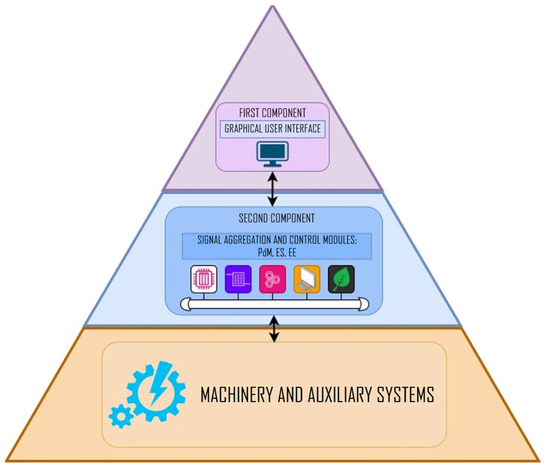
Figure 1.
Components of the monitoring and control system in IACMS (hardware/PLC and SCADA/HMI layer). Source: Authors’ own work.
3.1. Overview of IACMS Architecture
The IACMS system comprises several layers that cooperate with each other in real time. The lowest layer performs data acquisition functions and direct control of actuators, while the upper layers are responsible for trend diagnostics, technical condition prediction, and energy optimization. The PLC control layer has been designed to be fully compatible with existing shipboard systems, enabling integration with SCADA/HMI and with superior PMS and IAS systems. The functions of the expert system and predictive maintenance are not treated as separate modules, but rather as natural extensions of the IACMS architecture—the PdM and ES modules operate on the same measurement and event data and provide information used by energy optimization algorithms.
The system was developed using a redundant communication network, comprising two parallel Ethernet channels (Figure 2), which enables continuity of operation in the event of failure of one of the segments. In the operator layer, two redundant workstations have been used, operating in hot-standby mode.
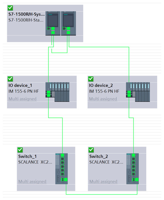
Figure 2.
Communication topology of the IACMS system in the TIA portal environment. Source: Authors’ own work.
3.2. Data Acquisition and Sensor Layer
The data acquisition layer forms the foundation of system operation, as the quality of measurements determines the accuracy of modeling, diagnostics, and optimization algorithms (Figure 3). The system collects data regarding LT/HT temperatures, pump flows, suction and discharge pressures, rotational speeds of pumps powered by frequency inverters, the states of control valves, and electrical parameters (currents, voltages, and power). The data is time-synchronized and filtered to eliminate disturbances characteristic of the marine environment.
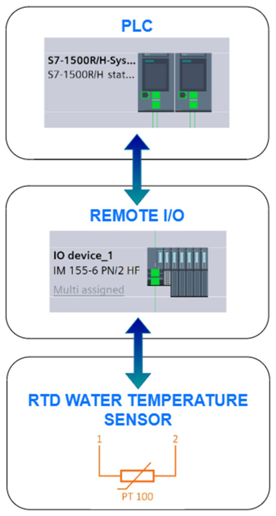
Figure 3.
Data acquisition layer in the IACMS system (sensors–I/O modules–PLC). Source: Authors’ own work.
Acquisition also includes diagnostic signals from pumps, heat exchangers, and frequency inverters, which are utilized by the PdM module. During data validation, outlier values, signal loss, and logical inconsistencies are analyzed, as they may indicate improper operation of equipment or sensors. Raw data and processed data are then transmitted to the PLC controllers, the analytical layer, and the expert module.
3.3. Control Layer
The control layer includes PLC controllers responsible for performing the basic control functions of the LT/HT system, including controlling the cooling water pumps in on/off mode, through variable frequency drive (VFD) speed regulation, and using adaptive flow profiles. The control logic has been implemented in ladder and sequential languages compliant with the IEC 61131-3 standard [38], which ensures both high operational transparency and the possibility of classification validation.
The controller is responsible for regulating the temperature of the cooling medium, controlling flow, and supervising the status of control valves. The controller’s structure incorporates interlock mechanisms, safety sequences, and fail-safe functions, enabling the maintenance of minimum cooling parameters even in the event of failure of the optimization modules (Figure 4). The control module also provides data for the expert system, which analyzes control decisions and indicates to the operator possible causes of improper system behavior.
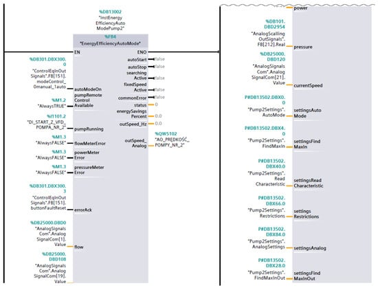
Figure 4.
PLC control layer for the main engine cooling system. Source: Authors’ own work.
3.4. Optimization and Decision-Making Layer
In the optimization layer (Figure 5), all elements of the system come together: current measurement data, diagnostic results, device state prediction, and the knowledge encoded in the expert module. Based on the current thermal load of the main engine, the condition of heat exchangers, flow parameters, and the power consumed by the pumps, the system generates recommendations or automatic decisions regarding the optimal setting of pump speeds, valve positions, and heat exchange strategies.
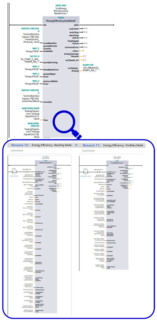
Figure 5.
Energy efficiency (EE) optimization module integrated with PdM and ES. Source: Authors’ own work.
The optimization algorithms use trend models and simplified physical models, and, when integrated with the PdM module, also take into account the state of health (SoH) of the devices and the estimated remaining useful life (RUL). Thanks to this, it is possible to implement energy-saving control strategies that not only reduce energy consumption but also minimize the risk of overloads or operation under conditions unfavorable to the durability of components.
In this work, the PdM/RUL functionality is implemented as an engineering-oriented, operational prognostic support integrated with the optimization layer. The approach is based on trend analysis and simplified physical reasoning, using routinely available diagnostic signals (current, temperature, and vibration) to compute condition indicators and to track their evolution over time. The remaining useful life (RUL) is estimated in a short-horizon manner as a time-to-threshold value obtained by extrapolating the dominant trend of selected indicators toward predefined alarm limits. The resulting SoH/RUL outputs are used by the supervisory logic to support safe operating constraints and maintenance recommendations, i.e., to avoid operating conditions that could accelerate wear or increase the risk of unfavorable dynamic loads. This PdM/RUL formulation is intended for short-horizon operational support and does not constitute a long-term failure-time prediction model without extended monitoring horizons and end-of-life observations.
The expert module supports the operator by interpreting signals and generating diagnostic comments, while the energy efficiency (EE) module is responsible for reliable assessment of the impact of control decisions on the overall energy balance of the engine room.
3.5. HMI and Supervisory Layer
The supervisory layer includes the HMI/SCADA system (Figure 6), which presents the operator with a complete overview of the operation of the LT/HT cooling system and other auxiliary devices. The operator interface enables visualization of process diagrams, trend charts, flow parameters, the status of pumps and valves, as well as detected anomalies. Modules are also available that present optimization recommendations, thermal load forecasts, and the results produced by the PdM and ES modules.
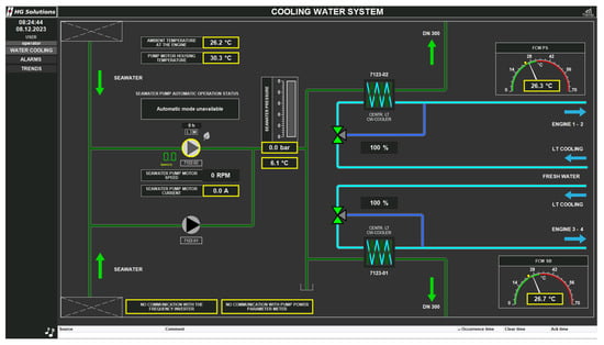
Figure 6.
HMI operator panel of the IACMS system—supervisory screen of the cooling system. Source: Authors’ own work (SCADA data).
In manual mode, the operator can override the system’s decisions, while in automatic mode, the HMI performs a supervisory function, ensuring the registration of system actions and the archiving of data necessary for energy validation. The system also enables viewing of reports from the diagnostic module, including alarms related to the operation of pumps, heat exchangers, and frequency inverters.
4. Energy Optimization Module for the Main Engine Cooling System
The main engine cooling system on marine vessels is organized as a two-loop system, comprising a high-temperature circuit (HT—high-temperature cooling system) and a low-temperature circuit (LT—low-temperature cooling system). In the HT circuit, the main engine components, such as the cylinder block and liners, are cooled, while the LT circuit absorbs heat from the lubricating oil cooler, air compressor, and additional auxiliary units. Both circuits are coupled through an HT/LT heat exchanger, and excess heat from the LT circuit is further transferred to seawater via a plate or tubular cooler.
In a typical configuration (Figure 7), the system is based on centrifugal pumps operating at a constant rotational speed, providing flow regardless of the current thermal conditions. Three-way or mixing valves are responsible for regulating the flow of the cooling medium between the bypass and the heat exchanger, maintaining the proper temperature at the engine inlet. The logic of the system is based on the assumption that the flow should always exceed the demand, which minimizes the risk of overheating but leads to excessive energy consumption.
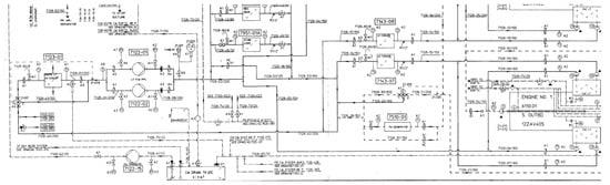
Figure 7.
Diagram of part of the main engine cooling system (LT/HT). Source: Authors’ own work (based on vessel technical documentation).
As a result, the traditional cooling system operates without feedback on thermal load, and the flow rate remains constant both when the engine is running at full load and during idle operation. This very characteristic makes the cooling system one of the most energy-intensive auxiliary systems on a vessel.
4.1. Baseline (Conventional) Strategy
In conventional cooling systems, the pump is driven by an electric motor operating at synchronous speed, regardless of the actual cooling demand (Figure 8). Temperature regulation of the medium is achieved through a three-way mixing valve, which adjusts the proportion of flow directed through the heat exchanger or bypass. This arrangement ensures that the cooling medium temperature is maintained at the level required by the engine manufacturer; however, this comes at the cost of significant energy losses.
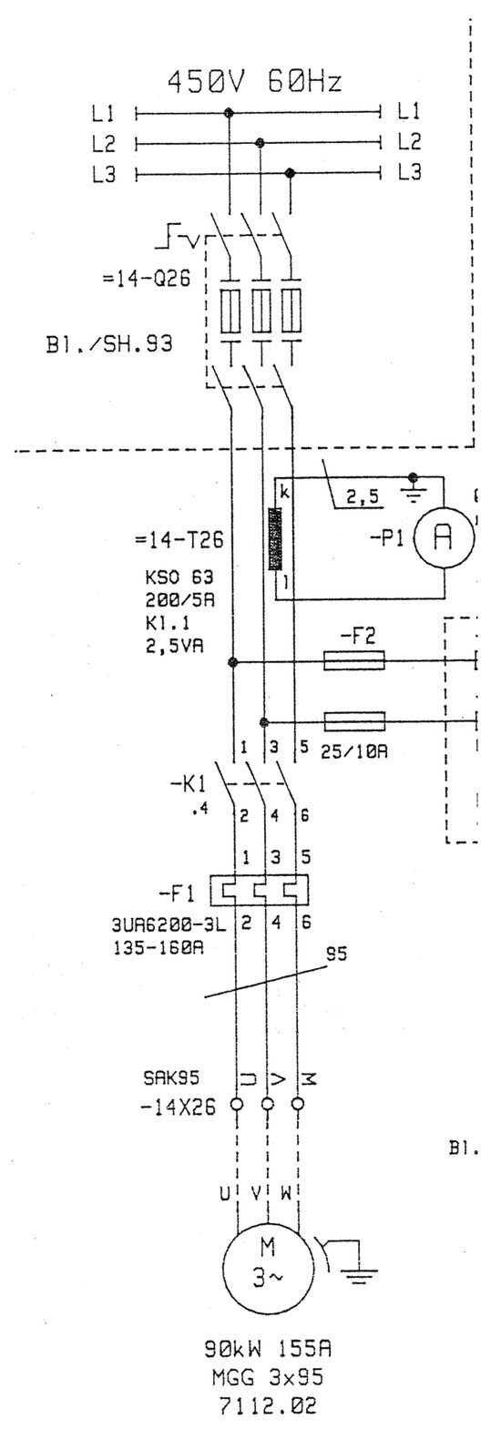
Figure 8.
Conventional cooling system control strategy (constant pump speed). Source: Authors’ own work (based on vessel technical documentation).
The use of constant-speed pumps leads to a range of unfavorable phenomena affecting both the energy efficiency of the system and its operational durability. Under conditions of low thermal load, the generated flow greatly exceeds the technologically required values, resulting in increased hydraulic losses in the installation and reduced overall efficiency of the cooling system. Constant operating speed also causes the pumps to maintain high power consumption regardless of the actual demand, making it impossible to optimally match energy use to changing operational conditions. Additionally, the inability to modulate performance leads to the need for periodic activation of standby pumps, resulting in redundancy enforced in a static manner, unrelated to the current state of the installation. A system lacking adaptive regulation is also incapable of responding to dynamic load changes, which limits the stability and effectiveness of the control process.
This conventional fixed-speed configuration is used in this study as the reference mode for evaluating the energy and thermal effects of demand-following pump speed control implemented within the IACMS framework.
4.2. Proposed Intelligent Control Strategy (IACMS Approach)
In the approach implemented in IACMS, the concept of constant flow and temperature regulation solely via a three-way valve has been abandoned. Instead, variable speed control of pumps using VFD inverters (Figure 9) has been introduced, allowing the flow rate to be adjusted to the actual thermal demand of the engine.
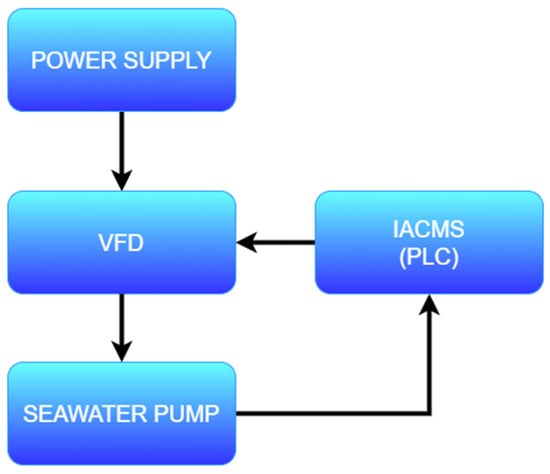
Figure 9.
Proposed IACMS control strategy with VFD regulation. Source: Authors’ own work.
The intelligent control strategy comprises three layers:
- (1)
- Adaptive regulation: The controller analyzes current LT/HT node temperatures and thermal load trends, smoothly adjusting pump speeds. This enables flow reduction under lower load conditions while maintaining temperatures within the required range.
- (2)
- Predictive component: The PdM module provides information on the health status of pumps, heat exchangers, and valves, allowing the avoidance of settings that would increase device load during periods when the RUL model indicates a risk of failure. In addition, trend models predict upcoming spikes in thermal load (e.g., during changes in engine speed), enabling proactive flow adjustment.
- (3)
- Expert system: The ES module analyzes the data and proposes settings that minimize energy consumption while maintaining safety margins. This includes recommendations on valve positions, operation of main and standby pumps, and heat exchange parameters.
For clarity, the energy-saving mechanism in this study is primarily delivered by variable-speed (VFD) demand-following control of the centrifugal pump. The full IACMS implementation extends beyond a conventional VFD-only solution by integrating continuous EEC/KPI computation and supervisory optimization support, condition-indicator trending with short-horizon RUL updates, and operator-oriented interpretation and recommendations within the PLC/SCADA architecture.
Thus, flow control becomes a function of the actual thermal load, rather than a predetermined nominal value. This represents a fundamental change in the philosophy of cooling system control.
4.3. Mechanisms of Energy Consumption Reduction in a Variable-Speed Pump System
The introduction of a VFD inverter in place of a constant-speed motor, along with replacing the three-way valve with flow control, results in a number of synergistic effects that together lead to significant energy consumption reduction:
- Reduction in pump rotational speed—nonlinear decrease in power consumption: The power consumed by the pump depends on the rotational speed according to the cube law. This means that reducing speed by 20% results in a power decrease of approximately 50%.
- Elimination of losses on the three-way valve: The mixing valve generates significant hydraulic losses and introduces variability to heat exchanger operating conditions. Flow control by the pump instead of by a valve improves the overall efficiency of the system.
- Stabilization of the thermal system: Pump speed regulation ensures smoother flow changes, which reduces temperature fluctuations, facilitates thermal load forecasting, and shortens the system’s response time.
- Optimal matching of flow to engine load: In a traditional system, the flow is too high under low load conditions. With IACMS control, the flow is only as high as required for heat exchange—no more.
- Lower mechanical load on pumps and valves: Reduced flow and gentler parameter changes decrease wear of mechanical components, which positively affects RUL.
- Possibility of eco-mode operation: IACMS enables automatic selection of the most efficient settings based on the analysis of historical data, predictive models, and recommendations from the expert module.
Figure 10 presents a typical characteristic of the power consumption of a pump as a function of the rotational speed of the drive motor. The curve clearly illustrates the nonlinear, exponential decrease in power with a reduction in rotational speed—in accordance with the cube law (P ~ n3). In practice, this means that even a small reduction in speed results in a significant reduction in energy consumption. For example, reducing the speed from 100% to 80% lowers power consumption to about 51% of the nominal value, which has been confirmed both in simulation studies and on the laboratory test stand.
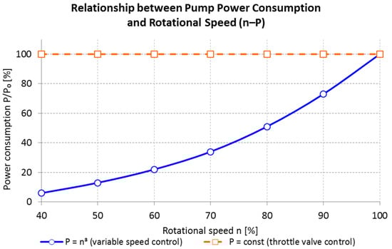
Figure 10.
Relationship between pump power consumption and rotational speed (n–P characteristic) for the seawater cooling pump drive (normalized values). Source: Authors’ own work.
Thanks to the integration of the VFD inverter with the IACMS system, it is possible to dynamically regulate pump rotational speed in response to the current thermal demand. This allows for synergistic effects in the form of electrical energy savings, reduced wear of mechanical components, and stabilization of operating parameters of the entire system.
By using variable pump speed regulation, a very significant reduction in energy consumption was achieved—for typical engine room operating conditions, for most of the operating time, it is sufficient to maintain system parameters at 70–90% of n0, which enables energy savings in the range of 40–70% compared to a classic system with a three-way valve.
4.4. Integration of the Optimization Strategy with the IACMS Control Layer
The optimization module transmits the generated pump speed setpoints and recommended valve positions to the PLC controllers, which execute the decisions while maintaining safety constraints. Sensor data is continuously sent to the PdM and ES modules, enabling real-time adaptation of control.
If safety thresholds are exceeded, the system automatically switches to conventional mode, using either a constant pump speed or operator-defined emergency logic. In this way, the IACMS architecture maintains compatibility with classification requirements and ensures continuity of cooling.
5. Experimental Setup
The estimation of the amount of electric energy E consumed by the pump drive over a given time interval T was carried out using the integral of the active power:
For discrete data recorded in the SCADA system with a frequency of 1 Hz, a summation approximation was applied:
In the case of the SONEL PQM-702 analyzer and the energy meter (e.g., MTR), the increase in energy reading from the measuring device was used directly:
where Estart and Eend are the readings of the accumulated energy at the beginning and end of the analyzed time interval.
For the quantitative assessment of the energy effect of IACMS control, an energy efficiency coefficient was defined as follows:
where Eref is the energy consumption in the reference mode (constant speed), and EIACMS is the energy consumption with IACMS control (IACMS/VFD).
The energy efficiency coefficient (EEC) defines the percentage reduction in electric energy consumed by the pump (or pump system) in IACMS/VFD control mode relative to the reference (baseline) mode at constant speed. In other words, the EEC indicates by what percentage less energy was used compared to the baseline measurement. In the literature, the energy efficiency coefficient (EEC) may also be referred to as the energy saving ratio (ESR) [39,40], energy saving percentage (ESP) [41], or energy reduction ratio (ERR) [42]. For example, EEC = 84.63% means that the energy consumption in IACMS mode was 84.63% lower than in the reference mode.
To improve transparency, uncertainty sources and their potential influence on the calculated EEC are briefly discussed. The EEC is calculated from accumulated energy measured over complete test intervals (laboratory runs and multi-hour voyages). Therefore, short-term signal fluctuations have limited influence on the final EEC value. The main uncertainty contributors are the accuracy and resolution of the applied energy measurement devices (SCADA-based active power integration, energy meter readings, and PQM analyzer), potential time-base misalignment between recorded channels, and operational variability of the system. In the present study, time series from different acquisition sources were synchronized and resampled to a consistent time base before evaluation. As a consequence, minor synchronization offsets primarily affect instantaneous comparisons but have a limited effect on accumulated-energy ratios used for EEC. While a full statistical uncertainty propagation is not feasible within the available campaign size, the manuscript provides a transparent qualitative assessment of these factors and reports repeatability evidence where available.
5.1. Laboratory Test Stand (IACMS—Verification Under Controlled Conditions)
In the first stage of the research, the IACMS system was verified under laboratory conditions, using an integrated educational and research test stand recreated according to the hydraulic and electrical diagrams provided in the project documentation. The stand included a real pump cooling system equipped with a centrifugal pump, a heat exchanger, a complete set of measurement sensors, and a PLC controller implementing the logic of the IACMS modules (PdM, EE, and ES) (Figure 11). According to the design, the hardware architecture replicated the shipboard system in terms of flow, temperature, pressure, and rotational speed measurements, using both analog signals and digital communication based on an industrial network.
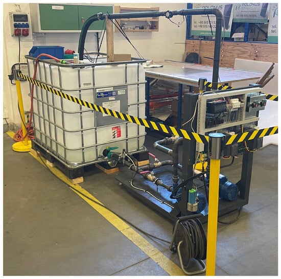
Figure 11.
Laboratory test stand for the cooling system controlled by IACMS. Source: Authors’ own work.
Data from temperature, pressure, and flow sensors was recorded with a resolution meeting the requirements of the diagnostic and predictive modules, while the pump motor speed was controlled via a frequency converter in the range of 20–60 Hz. The PLC controller implemented both classical PI regulator algorithms and adaptive flow control functions, as well as energy-saving logic, calculating the energy efficiency coefficient (EEC) in real time based on data from the built-in energy meter (Figure 12).
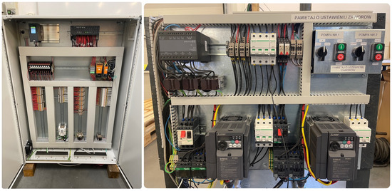
Figure 12.
Control cabinet of the IACMS prototype—hardware configuration of PLC and I/O. Source: Authors’ own work.
The laboratory test covered two basic operating variants: a reference mode, in which the pump operated at a constant rotational speed (VFD OFF), and an optimization mode, in which the EE controller regulated the supply frequency of the motor depending on the current thermal parameters of the system. Both the instantaneous power drawn by the motor and the accumulated energy were recorded, which enabled calculation of the actual energy gain.
Laboratory results showed very high effectiveness of inverter-based control. Documentation confirmed that for the tested pump system, an energy consumption reduction of 90.93% was achieved according to the EEC coefficient and 90.52% according to the actual energy meter. This resulted from the fact that in the reference mode, the system forced the pump to operate at a constant flow rate significantly exceeding the needs of the thermal system. Both results are fully consistent and form the basis for validation of the energy efficiency (EE) module before implementing the system on board.
During the laboratory tests, the correct operation of the PdM module was also verified. This module analyzed condition components: current, temperature, and vibration. The PLC controller generated measurement data at a frequency from 1 Hz to 10 Hz, which enabled subsequent reconstruction of waveforms and trend analysis for anomaly detection. The tests confirmed the capability to determine short-term RUL (remaining useful life) and the stability of algorithm operation under constant load conditions of the tested system.
5.2. System Verification Under Full-Scale Conditions on the MF Skania Ferry
The second stage included tests on the actual passenger and car ferry MF Skania, operating on the Ystad–Świnoujście route. The verification involved integrating the IACMS system prototype with the main engine seawater cooling system by retrofitting one of the seawater pump drives with a frequency converter and system measurement modules. The tests were conducted under operational conditions, without interfering with the vessel’s work schedule and while maintaining full operational continuity of the ship.
The seawater pump under analysis operated at a constant speed of 1189 rpm in the reference system, and thermal control was achieved by adjusting the degree of valve opening. After the implementation of the IACMS system, the pump motor was controlled by an inverter, which allowed smooth frequency regulation in the range of 30–60 Hz to maintain the coolant temperature below the project-specified limit value of 24 °C. This made it possible to reduce the flow of pumped seawater during periods of lower thermal demand, leading to reduced energy consumption.
To ensure complete diagnostics, the system was equipped with data recorders, including a SONEL PQM-702 power quality analyzer, which recorded the energy consumed by the generator set ZP1 at one-minute intervals. Additionally, the IACMS system acquired temperature and operational data from the Promotic SCADA system (Figure 13) at a frequency of 1 Hz, ensuring a full set of continuous records for dynamic analysis. The data included the freshwater temperature on the port and starboard sides (PS and SB), engine temperature, pump speed profiles, and the trend of electric energy consumed by the pump drive (Figure 14).
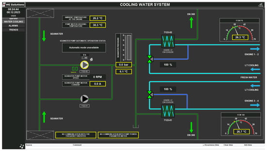
Figure 13.
HMI screen of the laboratory test stand—visualization of the cooling system. Source: Authors’ own work (SCADA data).
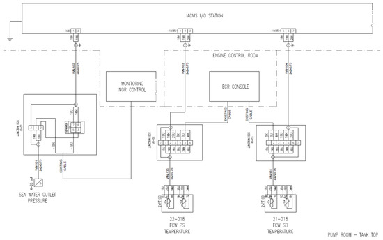
Figure 14.
Measurement diagram of the cooling system on the MF Skania Ferry. Source: Authors’ own work (based on vessel technical documentation).
Data registration covered two consecutive voyages: Ystad–Świnoujście and Świnoujście–Ystad. For each voyage, measurements were taken in both reference mode and with the IACMS system active (Figure 15), which enabled a reliable comparison of results under identical operating conditions. The use of the frequency inverter did not have a negative impact on the thermal operating conditions of the engines or on the freshwater temperature, which remained below the limit value of 24 °C throughout the entire test campaign. The temperature profiles showed smooth dynamics and no sudden fluctuations, confirming the correct integration of the IACMS system with the cooling circuit.
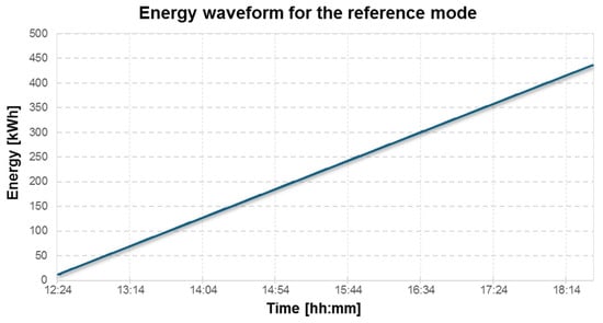
Figure 15.
Energy consumption trend of the pump in reference mode—full-scale tests. Source: Authors’ own work.
5.3. Methods of Data Recording and Synchronization
One of the key aspects of the experiment was the need to synchronize data originating from several independent sources. The SCADA system recorded thermal and operational parameters at a frequency of 1 Hz, while the PQM-702 analyzer recorded energy and electric power at intervals of one entry per minute. Additionally, the PLC controller archived diagnostic data from the PdM module at a frequency dependent on the input signals.
To standardize the analysis, all time series were rescaled to a common time axis and subjected to low-pass filtering to remove single measurement disturbances. Temperature data in 5 s intervals was presented as detailed charts, demonstrating the correctness of the sampling frequency and the stability of the readings (Figure 16).
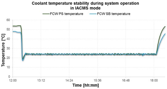
Figure 16.
Coolant temperature stability during system operation in IACMS mode. Source: Authors’ own work.
5.4. Operating Conditions During Voyages
The tests were carried out under the vessel’s normal operating conditions, during commercial voyages conducted according to the regular schedule. The thermal load of the cooling system resulted directly from the actual operation of the engines and auxiliary systems. The pump’s rotational speed was regulated by the frequency inverter solely based on current temperature values and trend changes, in accordance with the EE module algorithms. The IACMS system did not interfere with operator work and maintained the possibility of manual switching to reference mode, as required by classification regulations.
The voyages were performed on the same route and within a short time interval, with the same operating schedule, which limited the influence of external factors. However, it should be noted that, due to the commercial nature of the voyages, environmental differences (e.g., hydrometeorological conditions and vessel load) cannot be completely excluded; therefore, the results were interpreted as a comparison of representative system operating profiles.
6. Results
6.1. Laboratory Test Results—Reduction in Pump System Energy Consumption
In the first stage of the analysis, a series of tests were carried out on the laboratory test stand, with the aim of determining whether the EE (energy efficiency) module of the IACMS system is capable of effectively reducing energy consumption in a pumping system operating under controlled conditions. The test stand enabled direct comparison of two operating modes: the reference system with a constant motor speed, and the inverter-controlled system, where speed was dynamically selected based on the EE algorithms. The laboratory results unequivocally confirmed the effectiveness of the adaptive speed control approach (Figure 17). The accumulated energy recordings indicated that for the tested pump system, the energy gain reached 90.93% according to the energy efficiency coefficient (EEC) and 90.52% based on the actual energy meter reading. Both results are consistent and indicate that the use of the frequency inverter allowed for an almost tenfold reduction in the electric energy consumption of the motor without any negative consequences for the operating conditions of the thermal system.
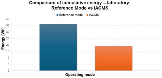
Figure 17.
Comparison of energy consumption—laboratory: Reference mode vs. IACMS. Source: Authors’ own work.
The physical mechanism responsible for this reduction was the decrease in the flow of pumped water during periods when the thermal demand was relatively low. In reference mode, the pump operated continuously, maintaining a flow rate that greatly exceeded the system’s requirements. Inverter-based control enabled the system to operate in a mode tailored to actual thermal needs, which resulted in a significant reduction in instantaneous power and accumulated energy.
The reference mode in the laboratory tests corresponds to fixed-speed operation at nominal frequency, representing a conservative baseline typical for many shipboard cooling installations that are designed with margins for worst-case thermal and hydraulic conditions and operational safety. Under such conditions, the reference mode may provide excess flow/head relative to instantaneous demand, which is commonly handled by throttling/valve arrangements. In contrast, variable-speed operation allows matching the delivered flow to actual demand, reducing both throttling losses and pump power in accordance with centrifugal pump affinity laws, which can lead to large relative reductions when the baseline is conservative.
The laboratory results thus provide a starting point for full-scale analysis and confirm that the IACMS system is capable of generating noticeable energy savings even before implementation on a seagoing vessel.
It should be noted that the laboratory test bench represents a controlled reference environment with stable boundary conditions (repeatable thermal load and hydraulic resistance). Therefore, the reduction observed in Section 6.1 reflects the achievable improvement under controlled conditions and a well-defined baseline point, which may differ from full-scale shipboard operation where boundary conditions and network losses vary dynamically.
6.2. Full-Scale Test Results—Analysis of Seawater Pump Energy Consumption on the MF Skania Ferry
The most important stage of IACMS system verification was the execution of full-scale tests on a real ship, under conditions fully reflecting daily operation. The tests were carried out on the passenger and car ferry MF Skania, during two consecutive voyages on the Ystad–Świnoujście and Świnoujście–Ystad route.
A comparison of both operating modes showed that adaptive regulation of the seawater pump’s rotational speed leads to a very significant reduction in energy consumption. In reference mode (direct supply, constant speed 1189 rpm), the energy consumed by the motor during the Ystad–Świnoujście voyage was 422,730 Wh, while in inverter control mode with the IACMS system, it dropped to 64,965 Wh. This means an energy reduction of 357,765 Wh and an energy efficiency coefficient (EEC) of 84.63%.
The return voyage showed an even greater difference. The energy consumed by the pump in reference mode was 561,003 Wh, while in inverter mode it was 78,594 Wh. In this case, the savings amounted to 482,409 Wh, corresponding to an EEC of 85.99%.
These voyage-level values are reproducible within the analyzed operating envelope and reflect the practical contrast between a conservative fixed-speed baseline and demand-following speed control. The magnitude of the achievable reduction depends on the vessel-specific cooling-network configuration and operating profile: savings tend to be smaller when the reference system already operates close to optimal flow/head (limited throttling) or when minimum-flow constraints and redundancy margins force operation at higher speeds. Therefore, the reported 84–86% reductions should be interpreted as representative for the analyzed ship and operating regime, while transfer to other ship types should be assessed against their local hydraulic/thermal envelope.
The reported voyage-level EEC values are obtained from accumulated energy over entire voyages; thus, they are inherently less sensitive to short-term disturbances and brief transient effects. Possible uncertainty sources include energy-meter/PQM accuracy and resolution, SCADA sampling, and synchronization between datasets recorded at different rates (e.g., 1 Hz process signals versus energy counters recorded at longer intervals). In this work, the recorded channels were aligned to a consistent time base prior to evaluation, and the comparison was performed over comparable operating segments. Within the available dataset, two consecutive voyages yielded closely aligned EEC values, which provides practical repeatability evidence for the tested operating regime. A broader statistical characterization of variability and confidence bounds would require a larger number of comparable voyages and extended monitoring horizons and is therefore indicated as future work.
These results confirm that VFD-based pump speed control implemented within the IACMS framework allows for a reduction in the energy consumption of the cooling system by over 84% while maintaining full stability of thermal parameters (Figure 18).
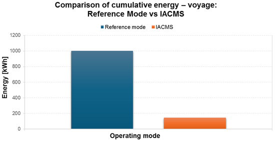
Figure 18.
Comparison of energy consumption—voyage: Reference mode vs IACMS. Source: Authors’ own work.
Local-level savings translate into significant cumulative values. For a daily voyage cycle covering both directions, the energy savings amounted to 840,174 Wh (about 0.84 MWh), which is a value that is both operationally and economically significant.
The difference between the laboratory reduction (~90%) and the voyage-level reduction (~85%) is primarily caused by the change from controlled boundary conditions to a complex full-scale shipboard environment. In the laboratory setup, the hydraulic resistance and thermal load are stable and repeatable, allowing the adaptive speed control to operate close to the most energy-optimal point for a given setpoint. During real voyages, several additional factors reduce the achievable relative reduction: seawater temperature and engine thermal load vary continuously, which changes the required flow and head; valve dynamics (mixing/bypass strategies) interact with speed regulation and can introduce additional losses that are not present or are minimized in the laboratory; the full-scale piping network introduces variable head components and additional pressure drops that depend on operating state; heat-exchanger fouling and condition-dependent pressure losses can shift the operating point over time; and operational safety constraints (minimum flow/pressure margins, redundancy requirements, and conservative limits imposed by the supervisory logic) can prevent operation at the lowest-energy speed in certain regimes. Consequently, the “unavoidable” portion of pump energy demand is higher in real operation, which reduces the relative EEC compared to the laboratory reference.
To systematically address the lab-to-real gap, future deployments should follow a structured reconciliation procedure: match the key similarity parameters between bench and onboard operation (e.g., representative flow/head envelopes for the pump); calibrate the simplified physical model using onboard measurements (pressure drop, temperature response, and valve position patterns); repeat the analysis across multiple voyages covering a wider range of seawater temperatures and engine load profiles, and report EEC as a range with sensitivity to operating envelopes rather than as a single-point value. This approach enables consistent translation of controlled test results into full-scale operational performance expectations.
6.3. Thermal Operating Parameters of the Cooling System and Regulation Stability
A key condition for implementing the IACMS system on a vessel was maintaining the coolant temperature below the permissible value of 24 °C. Analysis of the engine temperature profiles, freshwater temperatures on the port and starboard sides, and seawater temperatures showed that, throughout the entire measurement campaign, the IACMS system effectively kept all temperature values below the limit, regardless of operating conditions.
The profiles recorded at a frequency of 1 Hz show no sudden spikes or oscillations that could indicate improper flow selection by the EE algorithm.
The stability of thermal parameters is particularly important in the context of vessel operation, as it allows for a reduction in seawater flow while maintaining the thermal safety of the system. The results clearly indicate that inverter-based control not only does not worsen thermal conditions but actually enables better adaptation to current needs, avoiding operation with excessive flow (Figure 19).
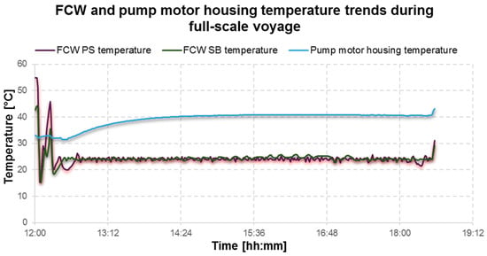
Figure 19.
Freshwater and engine temperature trend—full-scale voyage. Source: Authors’ own work.
6.4. Impact of the IACMS System on the Energy Consumption of Generator Sets
The full-scale test results also included an analysis of the energy produced by the generator set ZP1. Measurements taken with the PQM-702 analyzer showed that, during the reference day with the pump operating without the inverter, the total energy consumption was 8.7 MWh. In the following two days, when the pump operated in inverter mode, energy consumption decreased to 8.14 MWh and 8.07 MWh, respectively (Figure 20).
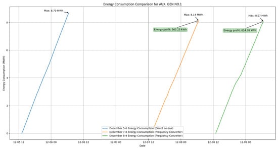
Figure 20.
Daily energy consumption of the generator set ZP1 during reference operation and IACMS-controlled pump operation. Source: Authors’ own work.
This corresponds to a reduction in energy drawn by ZP1 of 560.25 kWh and 624.38 kWh on consecutive days. If two generator sets operate in parallel with comparable load sharing during the analyzed period, the corresponding order-of-magnitude vessel-level difference would be approximately 1120.5 kWh and 1248.76 kWh, respectively; however, this extrapolation is indicative and depends on the actual load sharing of the generator sets.
It should be noted that the presented values refer to the total energy produced by ZP1 in a given day and therefore include other shipboard loads as well. For this reason, the impact of pump control should be regarded as the main identified factor in the observed differences for the analyzed period; however, without complete separation of all consumers, the partial contribution of operational changes cannot be entirely ruled out.
These results show that control of the seawater pump has a real impact not only on local energy consumption by the pump but also on the overall energy balance of the vessel. Although the contribution of a single auxiliary drive to the total generator set load is limited, an observed reduction of about 6–7% in daily generator-set energy during the analyzed period is already significant from the perspective of annual operating costs; however, this vessel-level value is indicative, as the generator supplies multiple onboard consumers.
6.5. Integration of Energy Results with Diagnostics and Technical Condition Prediction
An integral part of the IACMS system is the predictive maintenance module. The results recorded during the voyages—including current, temperature, and vibration signals—allowed for calculation of condition indicators and short-term remaining useful life (RUL). This data was updated on an hourly basis.
In the scope of this paper, the RUL output is treated as a short-horizon, operational estimate derived from the evolution of condition indicators (current, temperature, and vibration) and their trends. The prognostic output is formulated as a time-to-threshold indicator supporting the interpretation of whether the observed operating regime and speed regulation introduce unfavorable condition drift.
The analysis of condition trends showed that no degradation of the pump drive system was observed during the measurement campaign. All condition components demonstrated a stable or slightly increasing trend, resulting from the fact that the operating conditions were repeatable and the range of speed changes did not generate additional dynamic loads.
The correlation of energy results with diagnostic outcomes allows the conclusion that speed reduction does not significantly burden drive system components and, in many cases, can be beneficial by reducing the number of load cycles (Figure 21). This conclusion applies to the measurement campaign period; a longer observation horizon would increase the certainty of degradation trend estimation.
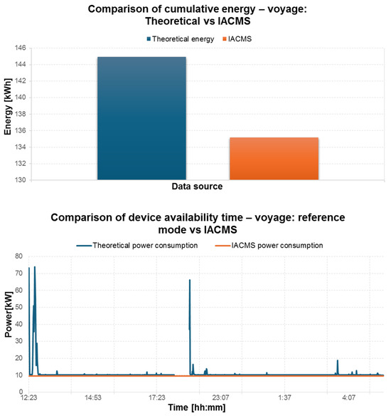
Figure 21.
Summary of energy savings—laboratory and full-scale voyage. Source: Authors’ own work.
Scope and validation limitations: The measurement campaign reported in this paper does not include end-of-life/failure events and does not constitute a long-term labeled dataset for data-driven lifetime modeling. Therefore, the manuscript does not claim full quantitative validation of RUL prediction accuracy using standard prognostic metrics (e.g., time-to-failure prediction error distributions). In this study, validation is limited to operational consistency checks: stability of condition trends during repeated operating profiles and the absence of abnormal degradation signatures within the campaign horizon. Accordingly, the present campaign supports conclusions on short-term operational stability, but it does not enable quantitative conclusions on long-term component reliability. A dedicated follow-up publication will address the predictive module in detail, including algorithmic variants, dataset structure, and quantitative validation metrics based on extended monitoring horizons. At the same time, while the manuscript demonstrates the operational use of PdM and expert decision-support layers (trend monitoring, hourly updates, and supervisory logic), long-term reliability improvement metrics require extended multi-month datasets and are beyond the scope of the present campaign.
6.6. Synthetic Comparison of Conventional Results and Those with the IACMS System
The entirety of the collected data indicates that the use of the IACMS system leads to multidimensional improvement in the operational efficiency of the cooling system. The key findings include the following:
- -
- A reduction in pump energy consumption by 84–86% compared to constant speed operation under real operating conditions;
- -
- An observed reduction in daily generator set energy by ~6–7% during the analyzed period (indicative, as the generator supplies multiple consumers);
- -
- Full thermal stability of the system, without exceeding permissible temperatures;
- -
- Consistent, stable diagnostics of the pump and its drive condition;
- -
- No negative impact of inverter-based control on the technical condition of the equipment.
This summary provides the basis for the final analysis and clearly confirms the validity and effectiveness of the IACMS system implementation.
To clearly distinguish the VFD-only effect from the additional IACMS layers, Table 1 summarizes the differences between the fixed-speed reference, a conventional VFD-only approach, and the fully integrated IACMS implementation used in this study.

Table 1.
Comparison of fixed-speed reference, conventional VFD-only control, and full IACMS implementation.
In summary, the proposed approach achieved an 84–86% reduction in seawater-pump electricity consumption in full-scale operation (and up to ~90% in laboratory conditions), maintained thermal stability, and showed stable condition indicators during the campaign, demonstrating practical feasibility of energy-efficient control under real ship operating conditions.
Potential limitations and transferability: The magnitude of achievable energy savings depends on the initial reference condition and the specific cooling-system configuration. In particular, differences in hydraulic network resistance, valve/mixing or bypass arrangements, minimum-flow constraints, redundancy and safety margins, as well as variability of thermal load and seawater temperature, may shift the operating envelope and affect the achievable EEC. Therefore, while the presented results demonstrate feasibility and strong benefits for the analyzed vessel and operating regime, implementation on other ship types should include site-specific tuning and verification against the local operating envelope.
7. Summary and Final Conclusions
The laboratory and full-scale test results presented in this article, conducted on the MF Skania ferry, clearly confirm that the integrated IACMS system developed within the project is an effective, practically deployable solution dedicated to energy-efficient operation of marine vessel cooling systems. By combining monitoring, control, energy optimization, and predictive diagnostics within a single architecture, the system enables a significant reduction in electric energy consumption while fully maintaining thermal stability and the operational requirements of engine room equipment.
The laboratory tests represented a key stage in the validation of inverter-based control algorithms, allowing their verification under controlled conditions. The results show that adaptive regulation of pump speed can reduce energy consumption by as much as 90%, due to the ability to precisely match the coolant flow to the actual system demand. This outcome was confirmed by both energy meter readings and the energy efficiency coefficient (EEC) generated by the EE module, demonstrating the consistency and reliability of the applied measurement method.
Equally important are the results of the full-scale system verification performed on the MF Skania passenger–car ferry. The use of an inverter and IACMS control logic in the seawater pump system led to energy consumption reductions of over 84% in each analyzed voyage, corresponding to a saving of approximately 0.84 MWh of electricity per day (Figure 22). These values are particularly significant given that cooling pumps are among the most energy-intensive auxiliary devices on a ship, operating continuously regardless of external conditions. The observed difference between laboratory and voyage-level EEC values is consistent with additional full-scale hydraulic losses and operational constraints; a systematic reconciliation framework is outlined to translate bench results into robust operational performance estimates.
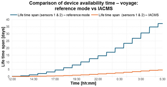
Figure 22.
Comparison of accumulated energy—voyage: Reference mode vs. IACMS. Source: Authors’ own work.
The impact of the IACMS system was also observed at the level of the vessel’s global energy balance. Analysis of the daily energy consumption of the generator set ZP1 showed a reduction of about 6–7% with the EE module active. Since the generator supplies multiple onboard consumers, this vessel-level reduction is indicative for the analyzed period and operating regime and should not be attributed solely to the seawater pump. The pump-level savings are quantified directly from pump measurements, while the generator-level result is reported as supportive system-level evidence.
It is worth emphasizing that the use of IACMS is not limited to reducing energy consumption. An integral part of the system is the predictive maintenance (PdM) module, enabling continuous analysis of the condition components of equipment—current, temperature, and vibration. During the voyages, no deterioration in the technical condition of the pump was observed, and the analysis of condition trends indicated stable or even improving values of diagnostic indicators. This means that speed reduction does not introduce additional dynamic loads on the drive system and, in the long term, may contribute to a decrease in the wear rate of pump and motor components. These results prove that IACMS creates a cohesive architecture in which the monitoring, diagnostics, prediction, and optimization layers do not operate independently but instead complement each other to generate a synergistic effect (Figure 23). Energy optimization influences the operating conditions of devices, while diagnostics enable continuous supervision of the impact of control on their technical state. Such an integrated architecture paves the way for the development of new methods for engine room management, where operational decisions are made based on real data and intelligent prognostic models.
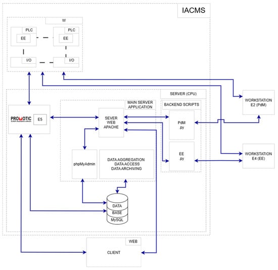
Figure 23.
Information flow and integration of IACMS modules (monitoring–diagnostics–prediction–optimization–control). Source: Authors’ own work.
From the perspective of the maritime industry, it is crucial that the presented system is not an experimental solution detached from operational realities. It was implemented for tests on a commercial vessel operating on a regular passenger schedule, without interfering with the ship’s operating schedule or endangering its safety. These tests were fully successful, and the obtained results provide real evidence of the system’s effectiveness in production conditions. Moreover, the prototype received certification from the Polish Register of Shipping, confirming its compliance with classification requirements and readiness for further implementation on seagoing vessels.
The final conclusions from the research clearly indicate that the IACMS system can play a key role in the energy transformation of ships, supporting shipowners in reducing fuel consumption, CO2 emissions, and operating costs. The functionalities related to predictive maintenance and intelligent process control not only improve energy efficiency but also increase equipment reliability and reduce unplanned downtime.
It is also important to highlight the measurable environmental impact of the IACMS system: the achieved reduction in electricity consumption translates directly into reduced CO2 emissions associated with onboard energy production. Assuming a conservative emission factor of 0.6 t CO2/MWh, implementation of the system allows for a reduction in greenhouse gas emissions of about 0.5 t CO2/day, which over the course of a year yields a potential saving of around 180 tons of CO2. This constitutes an important argument for the implementation of intelligent control solutions in the maritime transport sector, especially in the context of tightening IMO environmental requirements and decarbonization policies in shipping. The adopted emission factor represents an indicative CO2 intensity of onboard electricity generation and was selected as a conservative engineering estimate. It can be interpreted as a simplified product of the fuel carbon factor (CF, e.g., CF ≈ 3.206 t CO2/t fuel for MDO/MGO [43], as commonly used in IMO/EEDI-related methodologies) and a representative specific fuel oil consumption (SFOC) of auxiliary generator sets (dependent on load). Therefore, the CO2 savings reported in this paper should be understood as directly proportional to the assumed kg CO2/kWh factor. In practice, the effective CO2 intensity of onboard electricity varies with fuel type (e.g., HFO vs. MDO/MGO vs. LNG), generator efficiency, and the operational profile (load level and transient operation). Lower generator loading typically increases SFOC and thus increases CO2 per kWh, while operation closer to optimal load reduces SFOC and CO2 per kWh. Consequently, the absolute CO2 savings can be recalculated by multiplying the measured daily electricity savings by the emission factor appropriate for the specific vessel, fuel, and operating regime. For transparency, if the emission factor is varied within a plausible range (e.g., 0.5–0.8 t CO2/MWh), the corresponding daily CO2 reduction for the reported electricity savings of ~0.84 MWh/day would range from ~0.42 to ~0.67 t CO2/day, while the measured energy reduction itself remains unchanged.
The significance of the IACMS system extends beyond the case of cooling systems presented in this article. Its modular architecture enables integration with other engine room elements, including HVAC systems, fuel installations, compressed air systems, and energy balancing and storage systems. This opens the way to the development of comprehensive, intelligent energy management systems on ships, in line with the industry’s pursuit of automation and energy efficiency.
In conclusion, the presented results confirm that IACMS is an innovative, practical, and scalable solution that increases the energy efficiency of ship auxiliary systems. The developed optimization, diagnostic, and predictive tools, validated both in the laboratory and under real-world operating conditions, provide a solid foundation for further research and development work as well as wide-scale implementation of the system in the maritime sector.
Future work will present the predictive module as a dedicated study, focusing on detailed algorithmic formulation and quantitative validation metrics based on extended operational datasets.
Although PRS certification confirms classification-oriented readiness, adaptation to other class societies and IMO-related expectations requires separate rule-based assessment; nevertheless, the modular architecture presented here provides a clear pathway for such extension.
Author Contributions
Conceptualization: K.G., W.S., R.W., and A.Ł.; methodology: K.G., W.S., R.W., and A.Ł.; software: K.G., W.S., R.W., and A.Ł.; validation: K.G., W.S., R.W., and A.Ł.; formal analysis: K.G., W.S., R.W., and A.Ł.; investigation: K.G., W.S., R.W., and A.Ł.; resources: K.G., W.S., R.W., and A.Ł.; data curation: K.G., W.S., R.W., and A.Ł.; writing—original draft preparation: K.G., W.S., R.W., and A.Ł.; writing—review and editing: K.G., W.S., R.W., and A.Ł.; visualization: K.G., W.S., R.W., and A.Ł.; supervision: K.G., W.S., R.W., and A.Ł.; project administration: K.G., W.S., R.W., and A.Ł.; funding acquisition: K.G., W.S., R.W., and A.Ł. All authors have read and agreed to the published version of the manuscript.
Funding
This project was implemented under Priority Axis II Smart Growth 2014–2020, Measure 1.1 Support for Innovation Impulses.
Data Availability Statement
The original contributions presented in this study are included in the article. Further inquiries can be directed to the corresponding authors.
Conflicts of Interest
Authors Wojciech Skarbierz, Karol Graban and Ryszard Wnuk were employed by the HG SOLUTIONS Sp. z o.o. The authors declare that the research was conducted in the absence of any commercial or financial relationships that could be construed as a potential conflict of interest. The funders had no role in the design of the study; in the collection, analyses, or interpretation of data; in the writing of the manuscript; or in the decision to publish the results.
References
- IMO. Improving the Energy Efficiency of Ships. Available online: https://www.imo.org/en/ourwork/environment/pages/improving%20the%20energy%20efficiency%20of%20ships.aspx (accessed on 31 December 2025).
- Przybylowski, A.; Palewski, K.; Owczarek, T. Hydrogen Vehicle Adoption: Perceptions, Barriers, and Global Strategies. Energies 2025, 18, 5647. [Google Scholar] [CrossRef]
- Chen, Y.; Zhu, M.; Chen, M. Comprehensive experimental research on wrapping materials influences on the thermal runaway of lithium-ion batteries. Emerg. Manag. Sci. Technol. 2025, 5, E007. [Google Scholar] [CrossRef]
- Zhang, J.; Long, T.; Sun, X.; He, L.; Yang, J.; Wang, J.; Wang, Z.; Huang, Y.; Zhang, L.; Zhang, Y. Mechanism investigation on microstructure degradation and thermal runaway propagation of batteries undergoing high-rate cycling process. J. Energy Chem. 2026, 113, 1013–1029. [Google Scholar] [CrossRef]
- Kongsberg Maritime. K-Chief 700—Integrated Automation System; System Overview and Technical Description; Technical Documentation; Kongsberg Maritime: Kongsberg, Norway, 2020. [Google Scholar]
- Wärtsilä. Integrated Automation and Energy Efficiency Solutions for Marine Applications; Technical Brochure; Wärtsilä: Helsinki, Finland, 2020. [Google Scholar]
- Høglund Marine Solutions. Integrated Automation System (IAS)—Functional and System Description; Technical Documentation; Høglund Marine Solutions: Tønsberg, Norway, 2022. [Google Scholar]
- Praxis Automation. Mega-Guard VMS/PMS—System Description and Technical Specification; Technical Manual; Praxis Automation: Leiderdorp, The Netherlands, 2021. [Google Scholar]
- Rockson Automation. Evolution V5 IMCS—System Overview; Technical Brochure; Rockson Automation: Kiel, Germany, 2021. [Google Scholar]
- Totem Plus. IMACS Integrated Monitoring, Alarm & Control System; Totem Plus: Ramat Hasharon, Israel, 2023. [Google Scholar]
- MPL Techma. IAS—Zintegrowany System Automatyki Statku; MPL Techma: Chwaszczyno, Poland, 2025. [Google Scholar]
- Siemens AG. SISHIP—Integrated Automation and Energy Solutions. 2024. Available online: https://www.siemens-energy.com/global/en/home/products-services/product-offerings/marine.html (accessed on 15 January 2026).
- Mohamed-Seghir, M. Modern Method Based on Artificial Intelligence for Safe Control in the Marine Environment. TransNav 2023, 17, 283–288. [Google Scholar] [CrossRef]
- Abramowicz-Gerigk, T.; Burciu, Z. Design and Operational Innovations in Adapting the Existing Merchant River Fleet to Cost-Effective Shipping. Pol. Marit. Res. 2019, 26, 157–164. [Google Scholar] [CrossRef]
- Neumann, T. Development of ICT networks in maritime transport applications. In Advances in Maritime Technology and Engineering; CRC Press: Boca Raton, FL, USA, 2024; pp. 61–69. [Google Scholar] [CrossRef]
- Weintrit, A. Sustainable Reaction of the Maritime Education Sector to Marine Technology Development including Autonomous Surface Shipping. TransNav 2024, 18, 927–933. [Google Scholar] [CrossRef]
- PRS. Polish Register of Shipping (PRS)—A Recognized, Independent Appraisal Institution with Public Utility Status, Affiliated with the International Association of Classification Societies (IACS). 2026. Available online: https://prs.pl/en/prs-en/ (accessed on 15 January 2026).
- Ma, R.; Zhao, Q.; Wang, K.; Cao, J.; Yang, C.; Hu, Z.; Huang, L. Energy efficiency improvement technologies for ship in operation: A comprehensive review. Ocean Eng. 2025, 331, 121258. [Google Scholar] [CrossRef]
- Lan, T.; Huang, L.; Cao, J.; Ma, R.; Zhao, H.; Ruan, Z.; Wu, J.; Li, X.; Wang, K. A pioneering approach for improving ship operational energy efficiency: The quantitative application of deep learning interpretable results. Appl. Energy 2025, 400, 126554. [Google Scholar] [CrossRef]
- Xing, H.; Chang, S.; Ma, R.; Wang, K. EU MRV Data-Based Review of the Ship Energy Efficiency Framework. JMSE 2025, 13, 1437. [Google Scholar] [CrossRef]
- Yan, R.; Yang, D.; Wang, T.; Mo, H.; Wang, S. Improving ship energy efficiency: Models, methods, and applications. Appl. Energy 2024, 368, 123132. [Google Scholar] [CrossRef]
- Ba, Z.; Zong, Y. Research on Ship Optimization Energy Saving Technology Model Based on Internet of Things. In 2025 IEEE 3rd International Conference on Image Processing and Computer Applications (ICIPCA), Shenyang, China, 28-30 June 2025; IEEE: New York, NY, USA, 2025; pp. 1727–1731. [Google Scholar] [CrossRef]
- Qin, L.; Yin, Q.; Wang, Z.; Qian, W.; Jin, L.; Chang, X. A Method for Ship Energy Efficiency Data Cleaning Based on Interval Prediction. In 2025 8th International Conference on Transportation Information and Safety (ICTIS), Granada, Spain, 16–19 July 2025; IEEE: New York, NY, USA, 2025; pp. 1908–1915. [Google Scholar] [CrossRef]
- Talaat, W.M.; Banawan, A.A.; El-Gohary, M.M.; Ahmed, Y.M.; Abdelnaby, M.M. An EEDI based method to better the selection of form and propulsion parameters and improve energy efficiency during preliminary designs of single screw seagoing general/bulk cargo ship. Ocean Eng. 2023, 288, 116012. [Google Scholar] [CrossRef]
- Qiao, J.; Guo, G.; An, J.; Wu, G. Research on measurement and management of energy consumption distribution of ship engines. Front. Mar. Sci. 2025, 12, 3097. [Google Scholar] [CrossRef]
- Inal, Ö.B.; Koçak, G. A Case Study on the Variable Frequency Drive for Ship Engine Room Ventilation. Mar. Sci. Technol. Bull. 2023, 12, 252–258. [Google Scholar] [CrossRef]
- Theotokatos, G.; Sfakianakis, K.; Vassalos, D. Investigation of ship cooling system operation for improving energy efficiency. J. Mar. Sci. Technol. 2017, 22, 38–50. [Google Scholar] [CrossRef]
- Dere, C.; Deniz, C. Load optimization of central cooling system pumps of a container ship for the slow steaming conditions to enhance the energy efficiency. J. Clean. Prod. 2019, 222, 206–217. [Google Scholar] [CrossRef]
- Kocak, G.; Durmusoglu, Y. Energy efficiency analysis of a ship’s central cooling system using variable speed pump. J. Mar. Eng. Technol. 2018, 17, 43–51. [Google Scholar] [CrossRef]
- Su, C.-L.; Chung, W.-L.; Yu, K.-T. An Energy-Savings Evaluation Method for Variable-Frequency-Drive Applications on Ship Central Cooling Systems. IEEE Trans. Ind. Appl. 2014, 50, 1286–1294. [Google Scholar] [CrossRef]
- Jeon, T.-Y.; Jung, B.-G. A Study of PI Controller Tuning Methods Using the Internal Model Control Guide for a Ship Central Cooling System as a Multi-Input, Single-Output System. JMSE 2023, 11, 2025. [Google Scholar] [CrossRef]
- Jeon, T.-Y.; Lee, Y.-C. Energy Saving in Ship Central Cooling Systems: IMC-Tuned PID with Feedforward Control. JMSE 2025, 13, 510. [Google Scholar] [CrossRef]
- Pariotis, E.G.; Zannis, T.C.; Katsanis, J.S. An Integrated Approach for the Assessment of Central Cooling Retrofit Using Variable Speed Drive Pump in Marine Applications. JMSE 2019, 7, 253. [Google Scholar] [CrossRef]
- Wu, X.; Zhang, P.; Su, P.; Wu, J. Modeling and Key Parameter Interaction Analysis for Ship Central Cooling Systems. Appl. Sci. 2025, 15, 7241. [Google Scholar] [CrossRef]
- Jimenez, V.J.; Kim, H.; Munim, Z.H. A review of ship energy efficiency research and directions towards emission reduction in the maritime industry. J. Clean. Prod. 2022, 366, 132888. [Google Scholar] [CrossRef]
- Wang, K.; Wang, J.; Huang, L.; Yuan, Y.; Wu, G.; Xing, H.; Wang, Z.; Wang, Z.; Jiang, X. A comprehensive review on the prediction of ship energy consumption and pollution gas emissions. Ocean Eng. 2022, 266, 112826. [Google Scholar] [CrossRef]
- SELMA—Ship Electric Marine Control. SEES—Ship Energy Efficiency System Using VFDs on Auxiliary Machinery (Cooling Sea Water Pumps, LT Fresh Water Pumps, Engine Room Fans). 2020. Available online: https://www.selmacontrol.com/ship-energy-efficiency/ (accessed on 15 January 2026).
- IEC 61131-3:2025; Programmable Controllers—Part 3: Programming Languages. International Electrotechnical Commission (IEC): Geneva, Switzerland, 2025.
- Suh, S.-H.; Rakibuzzaman; Kim, K.-W.; Kim, H.-H.; Yoon, I.S.; Cho, M.-T. A study on energy saving rate for variable speed condition of multistage centrifugal pump. J. Therm. Sci. 2015, 24, 566–573. [Google Scholar] [CrossRef]
- Xu, X.; Feng, G.; Chi, D.; Liu, M.; Dou, B. Optimization of Performance Parameter Design and Energy Use Prediction for Nearly Zero Energy Buildings. Energies 2018, 11, 3252. [Google Scholar] [CrossRef]
- Wang, M.; Hu, E.; Chen, L. Energy-Saving Potential of Thermal Diode Tank Assisted Refrigeration and Air-Conditioning Systems. Energies 2022, 15, 206. [Google Scholar] [CrossRef]
- Togashi, E.; Miyata, M.; Yamamoto, Y. The first world championship in cybernetic building optimization. J. Build. Perform. Simul. 2020, 13, 391–408. [Google Scholar] [CrossRef]
- IMO. Resolution MEPC.245(66): 2014 Guidelines on the Method of Calculation of the Attained Energy Efficiency Design Index (EEDI) for New Ships. 2014. Available online: https://wwwcdn.imo.org/localresources/en/KnowledgeCentre/IndexofIMOResolutions/MEPCDocuments/MEPC.245%2866%29.pdf (accessed on 15 January 2026).


Disclaimer/Publisher’s Note: The statements, opinions and data contained in all publications are solely those of the individual author(s) and contributor(s) and not of MDPI and/or the editor(s). MDPI and/or the editor(s) disclaim responsibility for any injury to people or property resulting from any ideas, methods, instructions or products referred to in the content. |
© 2026 by the authors. Licensee MDPI, Basel, Switzerland. This article is an open access article distributed under the terms and conditions of the Creative Commons Attribution (CC BY) license.