Abstract
The development of robust and efficient wireless charging systems is essential for the widespread adoption of electrification in the transport sector, e.g., Electric Vehicles (EVs). Capacitive Wireless Power Transfer (CWPT) has emerged as a promising alternative to inductive methods, offering advantages such as lower cost, lighter structure, and reduced electromagnetic interference. However, the performance of practical CWPT systems, particularly systems employing simple L-type compensation networks, is severely affected by coupling plate misalignment, which causes variations in coupling capacitance. These variations give rise to a pseudo-resonance phenomenon, wherein conventional controllers, such as traditional Sliding Mode Control, mistakenly regulate reactive power to zero at an off-resonant frequency, leading to a drastic collapse in active power transfer. To overcome this limitation, this paper introduces a novel Adaptive Sliding Mode Control (ASMC) framework augmented with an online Recursive Least Squares (RLS) observer for real-time estimation of the time-varying coupling capacitance. The proposed dual-loop control structure integrates an inner adaptive loop that accurately tracks capacitance changes and an outer sliding mode loop that dynamically adjusts the inverter switching frequency to sustain true resonant operation. A rigorous Lyapunov-based stability analysis confirms global convergence and robustness of the closed-loop system. Comprehensive MATLAB/Simulink R2025a simulations validate the proposed approach, demonstrating its capability to maintain zero reactive power and stable 35 kW power transfer with over 95% efficiency under dynamic misalignment conditions of up to 30%. In contrast, a conventional SMC approach experiences severe pseudo-resonant collapse, with output power degrading below 1 kW. These results conclusively highlight the effectiveness and necessity of the proposed ASMC-RLS strategy for achieving robust, misalignment-tolerant CWPT in high-power EV charging applications.
1. Introduction
The global transition to electric vehicles (EVs) is accelerating, necessitating the development of charging infrastructure that is not only powerful and efficient but also convenient and automated []. In this context, Wireless Power Transfer (WPT) has emerged as a pivotal technology, eliminating the need for physical connectors and cables and enabling future integration with autonomous driving for dynamic in-motion charging [].
Historically, Inductive Power Transfer (IPT) has been the dominant approach, leveraging magnetic coupling through coils to deliver power over small air gaps []. However, IPT systems are inherently susceptible to misalignment between transmitter and receiver coils; a lateral displacement of just 20 cm can reduce efficiency by over 30% []. Furthermore, their strong alternating magnetic fields cause significant eddy current losses in nearby metallic objects and raise electromagnetic interference (EMI) concerns, posing challenges for high-power and public applications [].
Capacitive Wireless Power Transfer (CWPT) has recently gained significant attention as a promising alternative. Instead of magnetic fields, CWPT utilizes electric fields for energy transfer through coupling plates []. This fundamental shift offers several distinct advantages like (i) superior misalignment tolerance due to the electric field’s slower decay with distance, (ii) negligible eddy-current losses, reduced system weight and cost by eliminating bulky litz-wire coils, and (iii) lower EMI emissions [,]. These characteristics make CWPT particularly suitable for the dynamic and safety-critical environment of electrified vehicle charging, e.g., ground EVs, offshore vessels, and aerospace vehicles.
A critical component of any CWPT system is its compensation network, which resonates with the coupling capacitance to enable efficient power transfer. Research has explored various topologies, from simple L-series compensation to complex cascaded networks like LCL and LCLC [,]. While higher-order networks offer benefits like inherent filtering and reduced sensitivity to parameter variations, their complex structure, involving multiple inductors and capacitors, makes them difficult to control dynamically and increases the component count on the EV side [].
In contrast, the L-type matching network, comprising a single primary-side inductor, offers a simpler, lower-cost, and lighter solution, which is a significant advantage for the receiver-side design in EVs []. However, this simplicity comes with a critical drawback: the performance of an L-type network is exquisitely sensitive to its operating frequency. Its impedance characteristic is sharp, meaning that even a minor deviation from the exact resonant point, a near-inevitability during dynamic charging due to varying coupler misalignment, leads to a drastic increase in impedance and a consequent collapse of output power and efficiency [].
This sensitivity has motivated the development of advanced control strategies. While conventional controllers like PID are effective for linear time-invariant systems, they fail to handle the nonlinear, time-varying dynamics of a CWPT system under misalignment []. To address this, robust control techniques have been investigated. Among them, Sliding Mode Control (SMC) has shown great promise due to its inherent robustness to model uncertainties and external disturbances []. The conventional SMC method successfully regulates the reactive power (Q) in the circuit to zero, a necessary condition for resonance [].
However, a critical research gap identified in prior work is the phenomenon of “pseudo-resonance.” As demonstrated in [] and critically analyzed in our study, conventional Equivalent Sliding Mode Controller (ESMC) can force the reactive power to zero even when the system is not at the true resonant frequency. This occurs because the controller uses a fixed, nominal value for the coupling capacitance, , in its control law. When misalignment causes to vary, the controller drives the system to a false operating point where , but the LC network presents a high impedance, behaving as an effective open circuit. Consequently, while the control objective of zero reactive power is technically achieved, the overall system functionality fails, as the transferred active power collapses to nearly zero. This reveals a fundamental limitation: driving Q to zero is a necessary but insufficient condition for maximum power transfer. To guarantee true resonant operation, where the LC tank behaves as a short circuit for maximum power, the controller must also ensure the operating frequency dynamically matches the true, time-varying resonant frequency, . This necessitates an adaptive control law that updates its parameters with the precise value of during misalignment.
While parameter estimation techniques like the Extended Kalman Filter (EKF) exist, their computational complexity makes them less suitable for real-time control in this application []. The Recursive Least Squares (RLS) algorithm, an artificial intelligence (AI) method known for its computational efficiency and convergence properties, presents a more practical solution for real-time parameter estimation []. Still its integration with an adaptive SMC framework specifically to solve the pseudo-resonance problem in L-type CWPT systems remains underexplored.
This paper bridges this gap by proposing a novel Adaptive Sliding Mode Control (ASMC) strategy integrated with an AI-RLS-based online capacitance estimator for L-type CWPT systems. The key contributions are as follows:
- -
- A critical analysis and demonstration of the “pseudo-resonance” limitation in conventional ESMC, formally framing the control problem for a system with time-varying coupling capacitance.
- -
- The development of a dual-loop control architecture: An inner loop uses a computationally efficient RLS observer for real-time estimation of , while an outer ASMC loop uses this estimate to dynamically regulate the inverter’s switching frequency.
- -
- A rigorous stability analysis for the closed-loop system using Lyapunov theory, incorporating a projection operator to ensure bounded parameter estimates.
Comprehensive simulation validation demonstrates that the proposed method maintains over 95% efficiency and stable 35 kW power transfer under significant misalignment, effectively eliminating the pseudo-resonance problem and drastically outperforming conventional ESMC.
The remainder of this paper is organized as follows: Section 2 provides a system overview and problem formulation. Section 3 details the system modeling and power expressions. Section 4 presents the design of the proposed ASMC and RLS observer. Section 5 discusses the simulation results, and Section 6 concludes the paper.
2. System Overview and Problem Formulation
This section provides a concise overview of the L-type CWPT system, explains the rationale for selecting its compensation topology, and formally frames the core control challenge addressed in this work.
2.1. The Role of Compensation Networks in CWPT
Capacitive couplers inherently exhibit low impedance at high frequencies. Without proper compensation, this can result in excessive reactive currents and significant conduction losses, severely limiting power transfer efficiency. Compensation networks are therefore necessary to counteract the coupler’s reactance and establish a resonant tank.
Among common compensation topologies, higher-order LC or LCLC networks offer advantages such as current-source behavior, reduced sensitivity to coupling variations (due to misalignment of the primary and secondary plates), and potential voltage gain []. However, their complexity complicates parameter tuning and real-time mode-based controller design. Moreover, these approaches typically require a bulky compensating network on the EV side, which is undesirable due to strict weight and space constraints, making them less practical for automotive applications where compactness and simplicity are essential.
The L-type (series) compensation network consisting of a single series inductor with the coupling capacitor , is much simpler. Its low component count, ease of analysis, and suitability for lightweight EV-side systems make it the preferred choice for this work. The system architecture, as shown in Figure 1, comprises a high-frequency inverter, the L–C compensation–coupling stage, and a full-bridge rectifier that feeds the EV battery load .
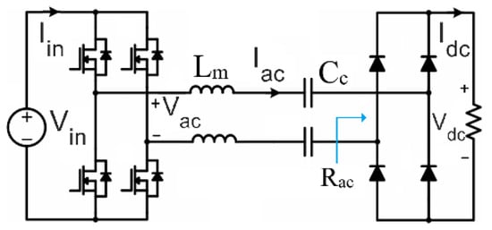
Figure 1.
The L-type (series) compensation network for CWPT.
2.2. Operational Challenges: Frequency Sensitivity and Dynamic Misalignment
The CWPT system ideally operates by driving the series LC tank at its resonant frequency, where the network impedance is minimized and purely resistive. At resonance, reactive power is eliminated, the voltage across the load is maximized, and power transfer efficiency is optimal.
However, the LC network exhibits a sharp impedance variation around its resonant peak due to its high-quality factor []. Even minor deviations from the exact resonant frequency, caused by variations in , can lead to a substantial increase in impedance, collapsing the output voltage and active power. Additionally, when the capacitive coupler is not fully compensated by the series inductor, such as under misaligned plate conditions, a significant reactive power can develop in the AC part of the circuit. This reactive power results in extra conduction losses, which are considerable at high frequencies due to the presence of large parasitic resistances in the LC branch originating from skin and proximity effects.
In dynamic EV charging, lateral and vertical misalignments make time-varying. Conventional controllers, such as fixed-parameter conventional Sliding Mode Control, cannot track these variations in real time. While they may drive the measured reactive power to zero based on nominal capacitance, the system may still operate off the true resonant frequency, leading to the so-called pseudo-resonance phenomenon. At pseudo-resonance, reactive power appears minimized, but active power and output voltage collapse, degrading system performance.
2.3. Problem Formulation
The control problem addressed for an L-type CWPT system with time-varying coupling capacitance and design a control law for the inverter frequency that ensures:
- A-
- Convergence of reactive power to zero:
- B-
- Tracking of the true resonant frequency:
- C-
- Maximization of active power transfer to the load under dynamic misalignment.
Analytical power expressions and frequency-dependent relationships, which form the foundation for the proposed controller design, are derived in Section 3.
3. System Modeling and Power Expressions
As mentioned in the previous section, the CWPT system is driven by a square-wave AC voltage. However, due to the sharply frequency-dependent impedance of the resonant LC branch, which effectively acts as a band-pass filter, only the fundamental frequency component contributes to power transfer to the secondary side. Consequently, the power calculation can be based solely on the fundamental component, expressed as:
This voltage, , drives the LC compensation–coupling branch along with a resistive AC-equivalent load (representing the rectifier and DC load as seen from the AC side). The impedance of the compensation and coupling branch is given by:
where is the mutual inductance and is the coupling capacitance. Let and denote the peak AC by
3.1. Active and Reactive Power Expressions
Using standard phasor relations, the instantaneous complex power delivered by the inverter to the AC branch has real (active) and imaginary (reactive) parts. With the phasor relationships above, the average power and reactive power are
and
where is the phase angle between voltage, current, and , .
Equations (5) and (6) give the closed-form frequency dependence of active and reactive power for the series LC branch with a resistive load.
3.2. Resonance Condition and Power Extrema
The resonant angular frequency of the LC branch is the root of the reactive term:
Substituting into (2) yields i.e., the reactive power vanishes at resonance. Physically, at the inductive and capacitive reactances cancel, so the reactive branch behaves like a short circuit, and the effective impedance equals ; consequently, all available AC voltage drops across .
The active power at resonance from (5) becomes
Because the denominator in (5) is minimized (the imaginary term is zero) at , is the maximum achievable active power for the given and . Thus, resonance both cancels reactive power and maximizes active power transfer to the load.
3.3. Expression for
The sliding-mode controller in Section 4 requires the derivative of reactive power with respect to frequency:
Using (6) and applying the quotient rule (or symbolic differentiation), one obtains the closed form:
which is algebraically equivalent to the derivative obtained from (6). Equation (10) is convenient because it groups terms in powers of and highlights the dependence on physical parameters and the excitation amplitude .
A useful simplification occurs at resonance , where and the expression in (10) reduces to a compact form:
This simple closed form is important for the controller design because is positive and finite, which ensures that small adjustments in produce predictable changes in the reactive power close to resonance. In other words, near resonance the mapping between and is well conditioned and can be used reliably in the sliding-mode frequency update law.
3.4. Remarks
- Equations (5) and (6) show explicitly that forcing is necessary but not sufficient to guarantee full active power transfer unless the controller ensures the zero of the numerator in (6) is the same zero that minimizes the imaginary term in the denominator, i.e., the controller must place at the true resonance . This observation explains the pseudo-resonance problem: a controller that drives the measured to zero using incorrect or stale parameter values can still end up off the true resonance and thus yield severely reduced .
- The derivative (Equation (10)), and, in particular, its resonant value (Equation (11)), is used in the conventional-SMC/ASMC laws to relate frequency adjustments to changes in (see Section 4). The positive, closed-form resonant value (11) simplifies the design and tuning of gains near .
4. Controller Design Methodology
This section presents the design of the proposed ASMC with online coupling capacitance estimation, which enables the CWPT system to maintain exact resonant operation under varying misalignment conditions. The overall control strategy consists of an inner adaptive loop based on an AI-driven RLS observer for capacitance estimation, and an outer sliding mode loop for frequency regulation. The combination of these two mechanisms eliminates the pseudo-resonance phenomenon commonly observed in conventional sliding mode controllers.
4.1. L-Type Matching CWPT Topology
The CWPT system adopts an L-type matching network, which consists of a primary compensation inductor and a coupling capacitance between the transmitter and receiver plates. On the secondary side, only coupling plates, a rectifier, and the DC load are used, which is advantageous for EV applications with space and weight constraints. The inverter switching frequency is adjusted to satisfy the resonance condition:
when this condition is met, the reactance of the inductor and capacitor cancel each other, and the reactive power becomes zero. Consequently, the equivalent impedance seen by the inverter equals the AC load resistance, maximizing power transfer and system efficiency. The system topology is shown in Figure 2.
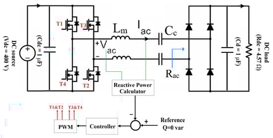
Figure 2.
The L-type compensator for CWPT chargers.
4.2. Sliding Mode Control Design
If the reactive power transferred through the LC branch is eliminated, the system operates under resonant conditions. In this state, the reactive branch effectively behaves as a short circuit, enabling maximum active power transfer to the EV. Essentially, the controller adjusts the output frequency of the DC–AC inverter to maintain zero reactive power. The first step in the control design is therefore to regulate the inverter frequency using ESMC. The sliding surface is defined based on the reactive power Q transferred through the compensation network:
where is the convergence gain. Differentiating the sliding surface and substituting the reactive power dynamics gives:
To ensure fast convergence, a saturation reaching law is used to avoid excessive chattering []:
where is the switching gain, is the boundary layer thickness, and . The control law guarantees Lyapunov stability which can be demonstrated by selecting the Lyapunov candidate and showing that [].
Although the conventional SMC can force , it suffers from the pseudo-resonance phenomenon. Due to uncertainties in the coupling capacitance value, the controller cannot guarantee that the system operates under resonant conditions. As a result, the amount of transferred active power and the overall power efficiency deteriorate significantly, especially under varying misalignment. This limitation motivates the development of an adaptive control strategy.
4.3. Online Capacitance Estimation Using AI-Based RLS Observer
Accurate and fast estimation of the coupling capacitance is crucial to overcome pseudo-resonance and maintain resonance under dynamic misalignment. An AI-based RLS observer is employed for the first time to estimate in real time from voltage and current measurements across the coupling capacitor.
4.3.1. RLS Formulation
The current–voltage relationship for the coupling capacitor is:
which can be expressed in regression form:
with , , and . The RLS algorithm minimizes the error between measured and estimated currents, updating recursively.
4.3.2. RLS Update Law
The observer structure and working process are illustrated in Figure 3. The RLS update equations are as follows:
where is the covariance matrix, initialized as ; is the forgetting factor; and is the Kalman gain. As the algorithm runs, decreases and converges to a small threshold (), indicating an accurate estimate of .
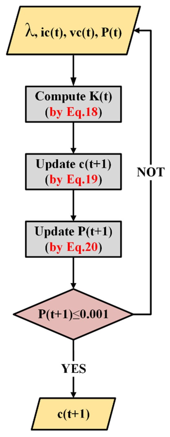
Figure 3.
Block diagram of the RLS observer used for real-time estimation of the coupling capacitance based on the measured voltage and current across the coupling plates.
It should be emphasized that the RLS observer detects the instantaneous value of the coupling capacitance online from the measured voltage–current relationship across the coupling plates. The reactive power , on the other hand, is measured directly from the inverter side and is used in the outer ASMC loop as the sliding variable. Thus, the proposed dual-loop structure distinguishes between the estimated parameter () and the measured control variable (), ensuring precise resonance tracking and robust stability.
4.4. ASMC Design
The ASMC incorporates the estimated capacitance into the control law through an online parameter adaptation mechanism. The uncertain coupling capacitance is represented as a parameter:
with its estimate updated in real time. This formulation allows the controller to simultaneously adapt to parameter variations and regulate frequency to maintain resonance.
4.4.1. Adaptive Law Derivation
The Lyapunov candidate function is chosen as follows:
where and is the adaptation gain. Differentiating gives the following:
The derivative of reactive power depends on both frequency and capacitance:
where and . By choosing the adaptive update law as follows:
the parameter estimation error term in is eliminated, leading to . This guarantees the convergence of both the sliding variable and the parameter estimation error .
4.4.2. Projection Operator
To ensure bounded parameter estimates and satisfy the Lipschitz conditions required by Barbalat’s lemma, a projection operator is used []:
The projection bounds correspond to a ±10% variation around the nominal capacitance. This prevents parameter drift and maintains stability under long-term operation.
4.4.3. Dual-Loop Control Architecture
The inner adaptive loop updates based on the RLS-estimated capacitance and the adaptive law, while the outer sliding mode loop adjusts the inverter frequency using the updated parameter. This ASMC–ESMC dual-loop structure is shown in Figure 4. In this multi-loop strategy, (i) the inner loop handles parameter uncertainty and capacitance variation, and (ii) the outer loop ensures zero reactive power and resonance by adjusting the inverter frequency. The proposed ASMC structure enables the controller to eliminate pseudo-resonance, track frequency during capacitance changes, and maintain resonance and high efficiency under dynamic misalignment.
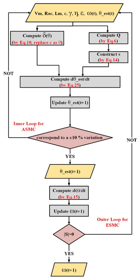
Figure 4.
Block diagram of the proposed dual-loop ASMC structure. The inner adaptive loop estimates the coupling capacitance in real time using the RLS observer and adaptive law, while the outer sliding mode loop regulates the inverter frequency to maintain zero reactive power.
4.4.4. Remarks on Applicability to Other Compensation Topologies and Scope
The controller and RLS observer presented above are derived and proven for the L-type (series LC) compensation topology used throughout this study. In such series LC tanks, the resonant angular frequency is given by
where is the effective capacitance seen by the primary side (in our model , the coupling capacitance). When misalignment alters the coupling capacitance, shifts smoothly and uniquely; the reactive power has a single zero crossing near and is finite in a neighborhood of resonance. These properties make the RLS estimator + ASMC frequency adaptation both well-conditioned and provably convergent under the Lyapunov framework proposed in this paper.
For other compensation networks, the situation is more nuanced. Consider two representative cases:
- Simple LC-based compensator (single additional LC): If the compensator topology is modified but the overall resonant behavior can still be represented by a single dominant resonant mode whose frequency depends on the coupling capacitance (i.e., effective is a monotonic function of the coupler geometry), then the ASMC–RLS architecture remains applicable with minimal modification: the estimator should be set to identify the equivalent capacitance (or equivalent reactance) relevant to that dominant mode, and the outer sliding law will then track the mode in the same manner as for the L-type case.
- Higher-order LCLC (cascaded) compensator: Higher-order networks typically exhibit multiple resonant modes (both series and parallel modes) and modal behavior that is not necessarily uniquely determined by the coupling capacitance. In particular, some resonant modes are mainly determined by local LC elements and are relatively insensitive to the coupling change; other modes result from interaction between transmitter/receiver tanks and depend strongly on the coupling coefficient. As a result:
- -
- can have multiple zeros (multiple candidate frequencies), and driving → 0 alone does not guarantee convergence to the desired power-transfer mode (risk of converging to an undesired zero).
- -
- A single scalar estimator for the coupling capacitance is generally insufficient because modal frequencies and coupling coefficients jointly determine the resonance condition.
Therefore, while the ASMC–RLS framework provides a general adaptive philosophy (estimate relevant parameters online and adapt inverter frequency to null the reactive component), extending it to LCLC and other higher-order compensators requires additional algorithmic steps: (i) multi-parameter online identification (e.g., vector RLS or recursive subspace methods) to recover modal frequencies and coupling coefficients; (ii) a mode-selection criterion (for example, joint maximization of active power in addition to to ensure convergence to the correct resonance; and (iii) an adapted stability proof that includes the multi-parameter estimator dynamics.
Scope and future work: The present paper focuses on the L-type (series LC) topology because it provides a minimal, lightweight receiver-side implementation with clear dependence of resonance on coupling capacitance; it therefore offers a clean testbed to demonstrate the ASMC–RLS principle and to provide a rigorous Lyapunov stability proof. A full theoretical and experimental treatment of more complex compensation networks (LCL, LCLC, etc.) is outside the scope of this manuscript. We explicitly propose the following directions for future studies: development of multi-parameter adaptive observers for modal identification, design of combined objectives (reactive-power nulling plus active-power maximization) to select the correct mode, and experimental verification of the extended algorithm under realistic parasitic and high-frequency effects. These extensions are necessary because the design details (estimator structure, controller gains, and stability arguments) depend on the compensator topology and the modal structure of the associated frequency response.
5. Simulation Results and Discussion
The performance of the proposed ASMC–RLS control strategy was evaluated through MATLAB/Simulink simulations, including steady-state, transient, and dynamic misalignment scenarios. The results validate the ability of the proposed method to maintain resonance, eliminate pseudo-resonance, and maximize power transfer efficiency under rapid coupling capacitance variations. The overall structure of the proposed closed-loop control system and all variables defining the simulation parameters are shown in Figure 5.
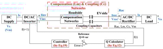
Figure 5.
The proposed robust misalignment-tolerant closed-loop system.
5.1. Steady-State Performance
Under the nominal system parameters listed in Table 1, the ASMC-based CWPT system maintains stable operation with closely matched input and output DC voltages and ripples below 5%, as illustrated in Figure 6a. However, the AC voltages contain higher-order harmonics due to the square-wave switching, as presented in Figure 6b. Similarly, the DC current ripple remains below 5%, while the peak AC current reaches 130 A (Figure 7). Since the converter operates at resonance, the system primarily transfers active power at the fundamental frequency; the high-order harmonic components are filtered and are not present in the AC current. With the inverter frequency matched to the resonant frequency, the reactive power is maintained at 0 var, and the DC output power stabilizes at approximately 34 kW, exhibiting minimal losses (Figure 8). Based on the simulation results, the control output, the AC voltage/current frequency, stabilizes at 0.5 MHz under nominal operation.

Table 1.
Nominal CWPT system parameters.
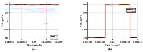
Figure 6.
Steady-state voltage waveforms under nominal coupling capacitance: (a) Input and output DC voltages; (b) Input and output AC voltages.
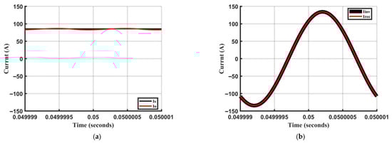
Figure 7.
Steady-state current waveforms under nominal coupling capacitance: (a) Input and output DC currents; (b) Input and output AC currents.
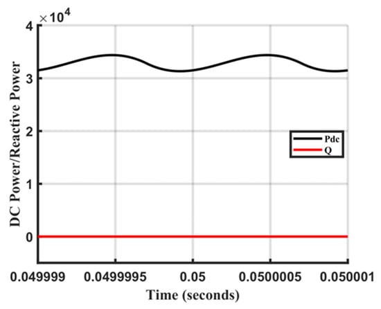
Figure 8.
Power transfer characteristics demonstrating resonant operation: Reactive power is maintained at 0 Var while the transferred active power is stabilized at approximately 34 kW.
5.2. Transient Misalignment Response Characteristics
To evaluate the controller’s adaptability, the system was tested under 10%, 20%, and 30% misalignment, corresponding to step changes in coupling capacitance. The RLS observer accurately estimated the new capacitance, allowing the ASMC loop to adjust the inverter frequency accordingly (Figure 9). The results indicate that the settling time of the AC output frequency increases from 25 ms at 10% misalignment to 45 ms at 30% misalignment. The output voltages and currents exhibit consistent transient behavior, as shown in Figure 10. Despite wide variations in the coupling capacitance across different misalignment scenarios, the proposed controller successfully eliminates reactive power transfer from the primary to the EV side, as demonstrated in Figure 11. Furthermore, after the transient period, the transferred active power remains nearly identical across all scenarios. This consistency is achieved because the controller continuously and precisely adjusts the frequency to maintain resonant operation in the LC-type coupler, causing it to behave as an effective short circuit. It is important to note that during the transient period, the reactive power can peak at approximately −17.5 kvar, underscoring the critical importance of rapid frequency adaptation. The extreme misalignment capability of the proposed ASMC–RLS controller is determined by the converter’s maximum switching frequency and the corresponding minimum achievable coupling capacitance. Based on the design parameters (L = 101.32 µH, Cref = 1000 pF, fmax = 1 MHz), the controller can maintain resonance for capacitance values as low as approximately 250 pF—equivalent to a 75% reduction in coupling capacitance. This corresponds to a wide misalignment range well beyond typical EV charging conditions. Therefore, the practical misalignment tolerance of the proposed method is primarily limited by coupler geometry and converter hardware, rather than by the controller itself.
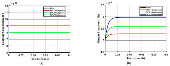
Figure 9.
Transient response of the proposed controller under misalignment, (a) Estimated coupling capacitance under different misalignment, and (b) operating frequency of the system generated by the proposed ASMC controller.
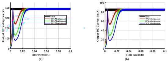
Figure 10.
Load characteristics under different misalignments, (a) output voltage, and (b) output current.
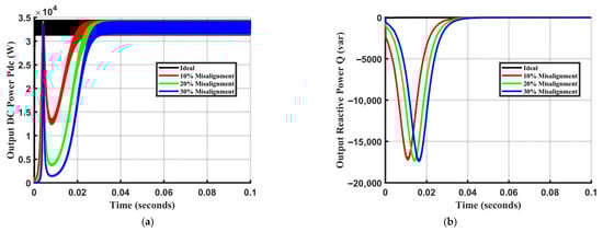
Figure 11.
Load characteristics under different misalignments, (a) transferred active power and (b) reactive power.
5.3. Performance Analysis of the Proposed ASMC with Conventional SMC Under Step Changes in Coupler Capacitance
A step change in coupling capacitance from 900 pF to 1100 pF was applied to compare the performance of the proposed ASMC–RLS system with a conventional SMC method, as proposed in []. It should be noted that under a misalignment (e.g., 10% in this test), the ESMC system does not update the coupler capacitance in the control equations. Hence, as shown in Figure 12, this results in a severe reduction in the LC circuit’s output voltage (Vrec) by a factor of 10 compared to the 400 V DC input, despite the reactive power converging to zero. Consequently, the transferred active power is significantly reduced. These results demonstrate that the conventional ESMC requires modification with real-time capacitance estimation to track the exact resonance frequency effectively. In contrast, during step changes in coupling capacitance value from 900 pF to 1100 pF, the proposed ASMC–RLS method accurately tracks the variations and updates the resonance frequency within 25–35 ms, as illustrated in Figure 13, thereby aligning the inverter’s output with the true resonant point.
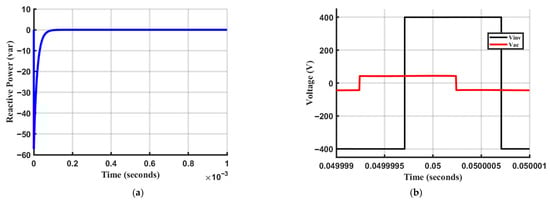
Figure 12.
Demonstration of the pseudo-resonance phenomenon using ESMC: (a) Reactive power converges to zero; (b) Output voltage () collapses despite zero reactive power, indicating operation at an incorrect resonant frequency ().
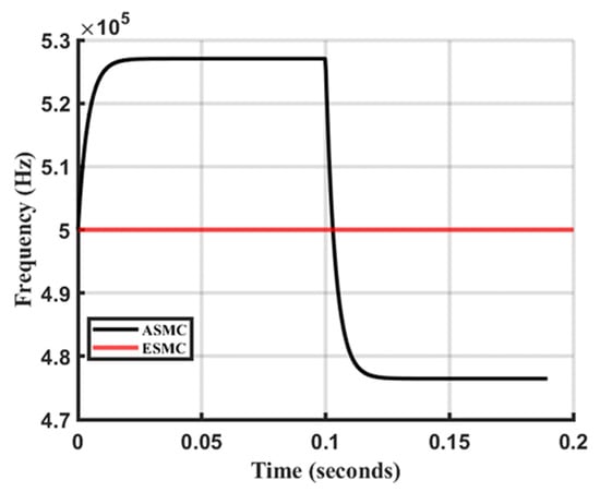
Figure 13.
Dynamic frequency tracking performance of the ASMC–RLS controller in response to a step change in coupling capacitance from to at .
In Figure 14, the response of the proposed ASMC is shown during start-up (with Cc = 900 pF) and during a step change in coupling capacitance (from 900 pF to 1100 pF) at t = 0.1 s. The results demonstrate that despite wide variations in coupling capacitance, the controller successfully eliminates reactive power transfer from the primary to the secondary side. This elimination of reactive current in the AC loop is critical for maintaining high system efficiency, as a significant portion of power loss in resonant converters is attributable to the proximity and skin effects. These effects cause high AC resistance in the inductive components at multi-MHz switching frequencies. By maintaining zero reactive power, the controller ensures that the generated active power is transferred efficiently through the capacitive coupler to the load.
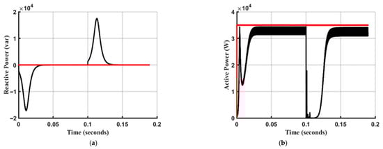
Figure 14.
Dynamic performance of the ASMC: (a) Reactive power regulation and (b) active power transfer during start-up () and a step change in capacitance from to at .
Figure 15 compares the load voltage and current for both the proposed ASMC and the conventional ESMC during start-up and a step change in misalignment. The results demonstrate that the ESMC fails to develop sufficient voltage across the load under misalignment conditions. This occurs because the system operates away from the resonant point due to the fixed switching frequency, causing the LC compensation network to present high impedance and block power transfer.
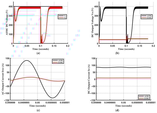
Figure 15.
Impact of misalignment on load voltage. The proposed ASMC maintains stable output, while the conventional ESMC fails due to the high impedance presented by the off-resonance LC network. (a) input DC voltage, (b) load voltage, (c) AC current, and (d) load current.
These results clearly illustrate the inherent sensitivity of the L-type compensation network to coupler misalignment. Given that misalignment is a common occurrence in practice, these results underscore the critical importance of adaptively updating the operating frequency. The proposed ASMC ensures that the output power of the charger remains stable and does not drop, thereby guaranteeing reliable operation in real-world dynamic charging scenarios. The results illustrate that the system utilizing the ASMC method achieves a DC output power of approximately 35 kW with over 95% efficiency, in stark contrast to the conventional ESMC, which delivers less than 1 kW.
The simulation results conclusively demonstrate that real-time capacitance estimation is the critical enabler for robust wireless power transfer under misalignment. By precisely tracking the resonant frequency, the proposed ASMC-RLS controller eliminates “pseudo-resonance,” maintains over 95% efficiency, and delivers a stable 35 kW. In stark contrast, the conventional ESMC, lacking this estimation, fails completely, with output power collapsing below 1 kW due to off-resonance operation.
The nominal power level of 35 kW was selected to represent the design target for practical dynamic CWPT chargers intended for medium-size electric vehicles, as reported in recent large-scale demonstrations by ORNL [] and CPE-PowerEng 2025 []. While this study focuses on simulation-based validation, the proposed control structure can be readily scaled down for experimental prototypes without loss of generality. The high-power specification ensures that the controller’s stability and robustness are evaluated under realistic, high-stress conditions relevant to dynamic EV charging.
6. Conclusions
This paper has addressed the critical challenge of misalignment-induced performance degradation in L-type Capacitive Wireless Power Transfer (CWPT) systems for electric vehicles (EVs). A thorough analysis identified and demonstrated the “pseudo-resonance” phenomenon, a key failure mode of conventional fixed-parameter controllers like ESMC, where reactive power is minimized without achieving true resonance or efficient active power transfer. To solve this problem, a novel dual-loop Adaptive Sliding Mode Control (ASMC) strategy integrated with an online AI-based Recursive Least Squares (RLS) estimator was proposed and developed for the first time. The controller’s architecture enables real-time, accurate estimation of the time-varying coupling capacitance, allowing the inverter frequency to adapt dynamically and maintain exact resonant operation. The stability of the closed-loop system was rigorously proven using Lyapunov theory. Simulation results under steady-state and dynamic misalignment conditions conclusively validated the effectiveness of the proposed method. The ASMC-RLS controller successfully eliminated pseudo-resonance, maintained zero reactive power, and delivered a stable 35 kW of power with high efficiency (>95%) despite significant coupling variations. In contrast, the conventional ESMC failed completely under misalignment conditions, with output power collapsing to negligible levels. These findings underscore that real-time parameter adaptation is not merely beneficial but essential for the robust operation of simple, lightweight CWPT systems in practical EV charging scenarios. The proposed approach provides a robust and practical solution, paving the way for more reliable and efficient dynamic wireless charging infrastructure.
Author Contributions
Conceptualization, P.A. and M.S.; Methodology, P.A. and M.S.; Software, S.C.; Validation, S.C.; Formal analysis, Q.D.; Data curation, Q.D. All authors have read and agreed to the published version of the manuscript.
Funding
This research received no external funding.
Data Availability Statement
The original contributions presented in this study are included in the article. Further inquiries can be directed to the corresponding author.
Acknowledgments
The authors would like to acknowledge the collaborative support and funding provided by both University College London (UCL) and the University of Greenwich, which made this research possible. This work was conducted as part of a joint research initiative between the two institutions, fostering an environment of innovation and interdisciplinary cooperation in the field of sustainable energy and electric vehicle technology.
Conflicts of Interest
The authors declare no conflict of interest.
References
- Zhang, Z.; Pang, H.; Georgiadis, A.; Cecati, C. Wireless Power Transfer—An Overview. IEEE Trans. Ind. Electron. 2019, 66, 1044–1058. [Google Scholar] [CrossRef]
- Li, S.; Li, W.; Deng, J.; Nguyen, T.D.; Mi, C.C. A Double-Sided LCC Compensation Network and Its Tuning Method for Wireless Power Transfer. IEEE Trans. Veh. Technol. 2015, 64, 2261–2273. [Google Scholar] [CrossRef]
- Mi, C.C.; Buja, G.; Choi, S.Y.; Rim, C.T. Modern Advances in Wireless Power Transfer Systems for Roadway Powered Electric Vehicles. IEEE Trans. Ind. Electron. 2016, 63, 6533–6545. [Google Scholar] [CrossRef]
- Covic, G.A.; Kissin, M.L.G.; Kacprzak, D.; Clausen, N.; Hao, H. A bipolar primary pad topology for EV stationary charging and highway power by inductive coupling. In Proceedings of the IEEE Energy Conversion Congress and Exposition, Phoenix, AZ, USA, 17–22 September 2011; pp. 1832–1838. [Google Scholar]
- Thrimawithana, D.J.; Madawala, U.K.; Neath, M. A Synchronization Technique for Bidirectional IPT Systems. IEEE Trans. Ind. Electron. 2011, 60, 301–309. [Google Scholar] [CrossRef]
- Huang, L.; Hu, A.P.; Swain, A.; Ren, Y.; Jeong, S.S. Efficiency Analysis of Capacitive Power Transfer System with a Shielded Power Track. IEEE Trans. Power Electron. 2019, 34, 615–625. [Google Scholar]
- Lu, M.; Thrimawithana, D.J.; Madawala, U.K.; Phan, B.T.T. A Matrix Coupler for Three-Phase Capacitive Power Transfer Systems. IEEE Trans. Power Electron. 2021, 36, 2637–2648. [Google Scholar]
- Ciric, K.N.M.; Liu, S.; Regensburger, G.R.; Chen, X. A Comparative Study of Capacitive and Inductive Coupling for Wireless Power Transfer. In Proceedings of the 2020 IEEE Wireless Power Transfer Conference, Seoul, Republic of Korea, 15–19 November 2020; pp. 445–448. [Google Scholar]
- Diekhans, T.; De Doncker, R.W. A Dual-Side Controlled Inductive Power Transfer System Optimized for Large Coupling Factor Variations and Partial Load. IEEE Trans. Power Electron. 2015, 30, 6320–6328. [Google Scholar] [CrossRef]
- Zhong, W.X.; Hui, S.Y.R. Analysis of LCLC Resonant Converters with Capacitive Output Filter for Inductive Power Transfer. IEEE Trans. Power Electron. 2018, 33, 4271–4282. [Google Scholar]
- Su, Y.; Dai, X.; Jiang, C.; Qahouq, J.A.A. A Review of Recent Developments in Capacitive Wireless Power Transfer Technology. IEEE Trans. Power Electron. 2022, 37, 2475–2492. [Google Scholar]
- Miller, J.M.; Jones, P.T.; Li, J.M.; Onar, O.C. ORNL Experience and Challenges Facing Dynamic Wireless Power Charging of EV’s. IEEE Circuits Syst. Mag. 2018, 18, 40–53. [Google Scholar] [CrossRef]
- Shadmand, M.B.; Balog, R.S.; Abu-Rub, H. Model Predictive Control of a Capacitive Power Transfer System for Optimal Efficiency and Power Transfer. In Proceedings of the 2016 IEEE Applied Power Electronics Conference and Exposition, Long Beach, CA, USA, 20–24 March 2016; pp. 2537–2542. [Google Scholar]
- Åström, K.J.; Hägglund, T. Advanced PID Control; ISA—The Instrumentation, Systems, and Automation Society: Research Triangle Park, NC, USA, 2006. [Google Scholar]
- Shtessel, Y.; Edwards, C.; Fridman, L.; Levant, A. Sliding Mode Control and Observation; Birkhäuser: Basel, Switzerland, 2014. [Google Scholar]
- Salimi, M.; Asef, P. Dynamic Wireless Charging Using Dynamic Frequency Tuning with Sliding Mode Control. In Proceedings of the ECCE Europe 2025, Birmingham, UK, 31 August–4 September 2025; IEEE: New York, NY, USA. [Google Scholar]
- Haykin, S.S. Adaptive Filter Theory, 5th ed.; Prentice Hall: Hoboken, NJ, USA, 2014. [Google Scholar]
- Ljung, L. System Identification. In Wiley Encyclopedia of Electrical and Electronics Engineering; Wiley: Hoboken, NJ, USA, 2015; pp. 1–19. [Google Scholar]
- Lian, J.; Qu, X. An LCLC-LC-Compensated Capacitive Power Transferred Battery Charger with Near-Unity Power Factor and Configurable Charging Profile. IEEE Trans. Ind. Appl. 2021, 58, 1053–1060. [Google Scholar] [CrossRef]
- Salimi, M.; Asef, P. Next-Generation EV Charging: Innovative Capacitive Wireless Power Transfer Through Harmonic Utilization. In Proceedings of the 2025 IEEE 19th International Conference on Compatibility, Power Electronics and Power Engineering (CPE-POWERENG), Antalya, Türkiye, 20–22 May 2025; pp. 1–7. [Google Scholar] [CrossRef]
- Gaudio, J.E.; Annaswamy, A.M.; Lavretsky, E.; Bolender, M.A. Parameter Estimation in Adaptive Control of Time-Varying Systems Under a Range of Excitation Conditions. IEEE Trans. Autom. Control 2021, 67, 5440–5447. [Google Scholar] [CrossRef]
Disclaimer/Publisher’s Note: The statements, opinions and data contained in all publications are solely those of the individual author(s) and contributor(s) and not of MDPI and/or the editor(s). MDPI and/or the editor(s) disclaim responsibility for any injury to people or property resulting from any ideas, methods, instructions or products referred to in the content. |
© 2025 by the authors. Licensee MDPI, Basel, Switzerland. This article is an open access article distributed under the terms and conditions of the Creative Commons Attribution (CC BY) license (https://creativecommons.org/licenses/by/4.0/).