Abstract
Unmanned Aerial Vehicles (UAVs) have limited flight time, which strongly depends on energy efficiency. This study investigates how control strategies based on fixed and variable roll, pitch, and yaw axes influence UAV energy consumption. Experimental tests were carried out during hovering and circular flights, with measurements of current, battery voltage, and total energy usage. The results show that different control configurations significantly affect power demand, with some dynamic maneuvers reducing energy consumption by up to 7% compared to hovering. These findings demonstrate that optimizing control algorithms and flight strategies can extend UAV endurance, which is particularly important for autonomous missions and applications requiring long operation times.
1. Introduction
1.1. Background and Motivations
One of the most frequently discussed issues in Unmanned Aerial Vehicles (UAV) design is its flight time. Extending it significantly increases the device’s utility across various sectors. For instance, in agriculture, extended flight time allows UAVs to cover larger areas [1], providing comprehensive monitoring [2], crop condition assessment [3], disease detection [4], and targeted spraying operations [5]. This improves productivity and enables precision farming techniques [6]. One of the main limitations in this field is the limited battery capacity of drones and the burdensome recharging process, which impacts operational efficiency [7]. Longer flights also enable UAV to carry heavier payloads, such as sensors or equipment, increasing their versatility in tasks like mapping [8], inspecting ventilation hatches [9], ship inspections [10], measurements, and delivery operations [11], among many others [12]. Sometimes, UAVs are integrated with other systems that can partially extend their flight time, for example, by transporting groups of drones closer to their target [13]. Extended flight time also enables long-distance missions, which is particularly beneficial for infrastructure inspections such as high-voltage lines [14], pipelines, or bridges [15]. In such cases, UAVs can monitor large areas without frequent landings to replace batteries.
1.2. Literature Review
Numerous studies are currently being conducted on selecting the appropriate components for UAVs [16], including battery types [17] and their lifespan [18], propellers [19], entire propulsion units, and motor configuration [20]. Some designs incorporate solar cells and hybrid propulsion systems, including hydrogen-powered ones [21]. Many research groups and companies compete to design devices that can remain airborne for as long as possible [22]. It is also possible to optimize flight through route planning [23], by searching for the shortest or, based on previous studies, the most energy-efficient path for a given device [24]. Trajectory optimization becomes even more complex when considering flights involving Unmanned Aerial Systems (UAS), i.e., larger groups of UAVs [25]. Therefore, it is crucial that the design in every aspect—structural, software, and control—aims to optimize energy consumption.
Currently, the market offers an “Autonomous UAV Battery Replacement System,” which significantly extends drones’ operational time by eliminating the need for manual handling and downtime during long missions [26]. This system functions as a separate device that, once installed at a designated location, enables the charging or replacing batteries when a UAV docks. Thanks to this solution, drones can efficiently carry out missions without the frequent need to land for battery changes, which enhances operational efficiency and enables prolonged activities [27]. Recent studies have also proposed wireless charging methods that, in theory, allow for continuous flight if the UAV remains within the charging field [28]. An analysis of current solutions shows that extending UAV flight time is achieved through multiple, sometimes independent, approaches.
Apart from the appropriate selection of components, the flight time is also significantly influenced by the UAV’s control method and route planning during flight [29]. The UAV’s trajectory is generated as a sequence of points, known as waypoints, which the drone must pass through during its flight [30]. Each of these points defines specific 2D/3D geographical coordinates that the device must reach, allowing for precise control of its movement and adherence to the planned path. These points can be reached through various flight configurations, which can be divided into two main strategies.
The first, currently the most popular, involves rotating the UAV so that the front of the device always faces the target. This strategy is particularly recommended when the vision system needs to be aligned with the direction of movement. In this configuration, the UAV rotates at the waypoint, stopping and entering a “hover” mode. It is also possible to make course corrections during the flight while maintaining a constant speed. Alternatively, the opposite flight strategy (second one) can be employed, where the device maintains a fixed yaw axis, preventing the drone from rotating and thus affecting how it reaches the designated waypoints.
However, relatively few studies have examined how different control configurations and flight dynamics influence energy consumption, which is the focus of the present research. In this context, the present study aims to experimentally evaluate how different control configurations affect the overall energy consumption of a multirotor UAV.
1.3. Problem Formulation
This paper presents research conducted using a four-motor, vertically launching drone, commonly known as a quadcopter. Its advantage lies in its excellent maneuverability, which allows it to move in any direction, hover in place, rotate on the spot, and tilt the device along the x, y, and z axes. Figure 1 presents an illustration depicting the movement capabilities of the four-motor drone.
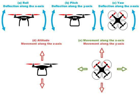
Figure 1.
Movement capabilities of a four-engine vertical take-off drone, commonly known as a quadcopter.
This study aims to determine the impact of certain UAV maneuvers during flight on energy consumption, to extend flight time. However, an analysis of UAV operation principles suggests that rotating the device does not always increase energy consumption. For the device to take off, condition 1A from Table 1 must be met, meaning the force generated by the four propulsion units mounted on the UAV must be greater than the gravitational force acting on the device (Figure 2). If these forces are balanced, the device can hover in place (condition 2A). A reduction in force, on the other hand, causes the UAV to descend (condition 3A).

Table 1.
Distribution of propulsion forces (F1–F4) for basic movements (A) and investigated maneuvers (B) of the quadcopter UAV.
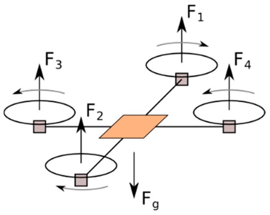
Figure 2.
Influence of the direction and rotational speed of the power units (motor + propeller) on the movement of the UAV.
In the case of a device rotating around its axis, the rotational speed of the motors spinning to the left is adjusted about those spinning to the right. The rising angular force rotates the device either clockwise or counterclockwise. Therefore, the rotation is performed merely by altering the power distribution among the propulsion units without increasing the total power (conditions 5A–6A). If the total power increased, the device would ascend or descend. Thus, during the rotation, condition two should also be fulfilled.
To ensure reliable results, it was assumed that the load on each power unit should be distributed evenly. Otherwise, higher energy consumption could naturally be observed depending on the maneuver. The structure used in the tests is symmetric concerning the roll and pitch axes. The device weighs 610 g, and the utilized 4000 mAh batteries weigh 290 g. The load on each power unit is 225 ± 15 g.
1.4. Contribution
This paper experimentally evaluates how fixed and variable control axes influence the total energy consumption of a quadcopter. The novelty of this work lies in the comparative analysis of control configurations that differ in the coordination of yaw, roll, and pitch angles—an aspect that has not been previously explored in the literature.
To investigate this, three characteristic flight configurations were analyzed, reflecting different control strategies commonly used in multirotor UAVs:
- i.
- Fixed yaw (condition 1B)—the UAV maintains a constant yaw angle relative to the global coordinate system and moves toward the target point by adjusting only the roll and pitch angles.
- ii.
- Continuous yaw adjustment (condition 2B)—the UAV continuously aligns its heading with the direction of travel, adjusting both the roll (for forward flight) and yaw (for course correction).
- iii.
- Continuous yaw adjustment with side tilt (condition 3B)—the UAV maintains its heading toward the target point while performing coordinated roll, pitch, and yaw changes that result in a smooth, banked turn.
The study aims to determine which of these control configurations provides the most energy-efficient flight profile. Two experimental scenarios were conducted:
- i.
- Hovering with both fixed and variable roll, pitch, and yaw angles, and
- ii.
- Circular flight at a constant speed.
Throughout all tests, the UAV’s altitude was kept constant to isolate the effect of control configuration on energy consumption.
2. Description of the Measuring System
The research was conducted in a specialized laboratory of size 12 m × 15 m × 6 m, secured with protective nets, foam panels, and a dedicated operator safety chamber. This environment minimized the influence of external conditions, such as wind, on the research results. An ultrasonic positioning system from Marvelmind was used during the experiments. The tested devices were designed and constructed with care to ensure an appropriate lift-to-flight time ratio. The final Class 300 design maintains an average flight time of 15 min.
The MATLAB R2024b-based software serves as a central monitoring and control system for up to five UAVs. A dedicated control module ensures reliable communication, integrating a radio link for data transmission and safety switches for emergency shutdown. Thanks to this architecture, the system is efficient and safe, which is crucial in research on autonomous drones.
2.1. Unmanned Aerial Vehicle (UAV)
The construction of UAV, including control methodology, is significant from the perspective of the conducted research. A quadcopter with a diagonal motor layout of 300 mm was constructed for the research.
The device is shown in Figure 3. The stabilization of the UAV and its flight capabilities were managed by Processor 1—STM32F722RET6, which had Inav 7.0 software installed. Processor 2—ESP-32 determined the directional vector based on data from the navigation systems. It then emulated the equipment to transmit control signals to Processor 1. As a result, the UAV followed the trajectory defined by the operator. The resulting controller and its peripheral components is depicted in Figure 4.
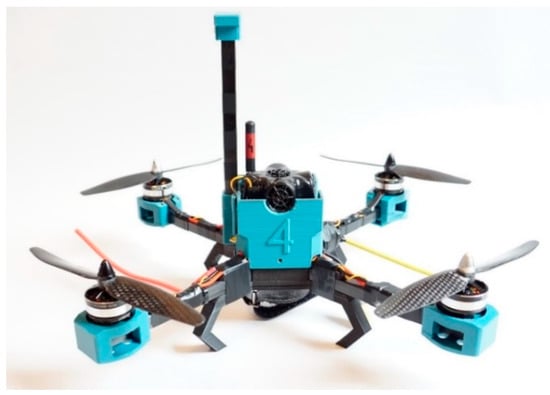
Figure 3.
UAV constructed for the research experiments.
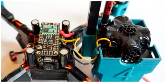
Figure 4.
Internal view of the UAV showing the sandwich controller (left) and navigation system (right).
A detailed technical specification is provided in Table 2. Throughout all the experiments, 3S 4000 mAh batteries from the same manufacturer and production batch were used, ensuring a similar number of charge cycles. The tests utilized new batteries with no more than 10 mΩ resistance. The current, voltage, and Energy consumption parameters were measured between the battery and the UAV power supply. Therefore, the recorded results should not account for potential energy losses due to battery heating.

Table 2.
Technical specifications of the UAV used in the experiments, including controller, sensors, propulsion system, and structural components.
2.2. Measurement System
All experiments were conducted using a proprietary system that included unmanned aerial systems, a control panel, an operator panel, and components of a radio network. This system enabled the testing of five UAVs connected into a single integrated system. While recording the published studies, only one device was used each time. A laboratory was established for the tests, referred to by the authors as the Laboratory of Autonomous Flying Systems. An ultrasonic indoor navigation system from Marvelmind was employed in the laboratory, providing a positioning accuracy of ±2 cm. During the experiments, spikes in the measured altitude were not visible to the eye. A camera with a recording frequency of 240 Hz was mounted along the z-axis to verify this maneuver.
For the research, software was developed using MATLAB App Designer, allowing for the initiation, monitoring, and processing of measurement data. Figure 5 shows one of the recorded measurements in which the device flew in a circular path for over 8 min.
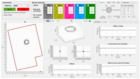
Figure 5.
Recording measurements during flight in dedicated software—User interface.
2.3. Measurement Methodology
One of the main issues addressed in this research is the increased energy consumption resulting from unnecessary device movements. It was assumed that providing only the path and recording energy consumption in three configurations might not yield accurate results, as the control system’s response could vary each time due to different movements.
Multiple flights were conducted during the work with the devices, recording control parameters and the device’s responses. The preliminary studies for training the UAS allowed for the determination of specific control parameters and system responses for simple shapes, such as line segments and circles.
During the tests of the hovering device, the roll and pitch angles remained at 0°, corresponding to a zero deflection of the control stick. A single PID controller ensured the maintenance of the device’s altitude while other parameters were adjusted based on previous values.
In this context, it was assumed that the position control system did not have feedback from the position in each configuration, and the control values were the result of model calculations. During the motion tests, the device maintained a constant speed of approximately 1.5 m/s.
The research was structured into two distinct stages: hovering flight and circular flight with a diameter of 2 m. Each stage was designed to systematically explore the energy consumption and control dynamics of the unmanned aerial vehicle (UAV) during various maneuvers.
During the hovering flight stage, four specific maneuvers were examined to highlight different aspects of the UAV’s performance:
- i.
- Overhang (No Rotation): This maneuver served as a baseline to assess the energy consumption and stability of the UAV while maintaining a fixed position without any rotational movement. It provided crucial insights into the power requirements solely for hovering.
- ii.
- Overhang with Rotation around the Yaw Axis: Introducing rotation around the yaw axis allowed us to analyze the energy costs associated with maintaining stability while changing the UAV’s orientation. This maneuver was essential for understanding how rotational movements impact overall energy efficiency.
- iii.
- Overhang with Mixed Rotation: In this maneuver, the UAV alternated its rotation direction every 2 s, simulating dynamic flight scenarios.
- iv.
- Overhang with Height Jumps: By incorporating height variations between 1 to 2.5 m, this maneuver assessed the UAV’s ability to manage vertical movements while hovering. It offered valuable data on how changes in altitude affect energy consumption and the stability of the device.
In the first, fixed yaw configuration shown in Figure 6:
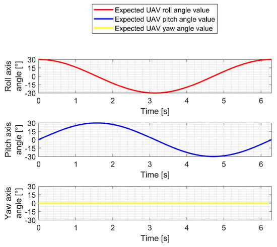
Figure 6.
Roll, Pitch, and Yaw angles of the tested UAV during a circular flight in the fixed yaw configuration.
- The roll axis (red line) makes smooth, sinusoidal movement (from 0° to 360°), which, in combination with the cosine movement (from 0° to 360°) of the pitch axis (blue line), generates a constant movement of the UAV around its axis.
- The drone holds a constant yaw axis angle (yellow line) of 0°, indicating no device rotation around its axis.
In the second, variable yaw configuration shown in Figure 7:
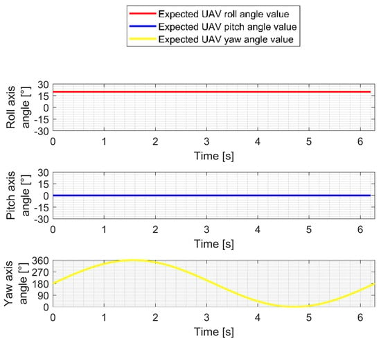
Figure 7.
Roll, Pitch, and Yaw angles of the tested UAV during a circular flight in the variable yaw configuration.
- The drone holds a constant roll axis angle (red line) of 20°, which indicates that the drone is tilted nose down, forcing it to move forward.
- The drone holds a constant pitch axis angle (blue line) of 0°, indicating no lateral tilt.
- The yaw axis (yellow line) shows a smooth, sinusoidal movement from 0° to 360°, which translates into a constant rotation of the UAV around its axis.
The third, continuous yaw adjustment and side tilt configuration shown in Figure 8:
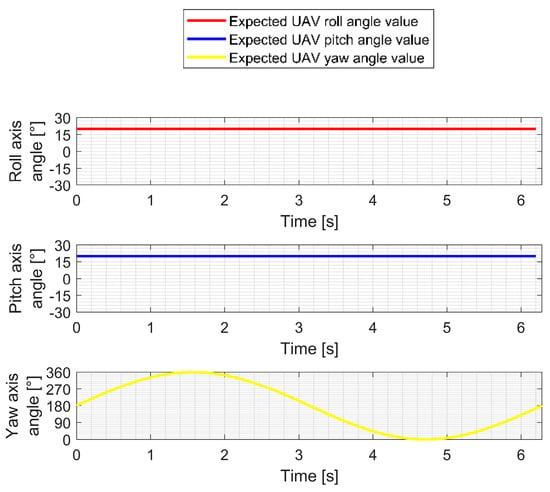
Figure 8.
Roll, Pitch, and Yaw angles of the tested UAV during a circular flight in the variable yaw and side tilt configuration.
- The drone holds a constant roll axis angle (red line) of 20°, which indicates that the drone is tilted nose down, forcing it to move forward.
- The drone holds a constant pitch axis angle (blue line) of 20°. The device makes a lateral tilt on the inside of the arc. The maneuver throws the device into the arc.
- The yaw axis (yellow line) shows a smooth, sinusoidal movement from 0° to 360°, which translates into a constant rotation of the UAV around its axis.
3. Research Results
Each measurement was repeated ten times under identical experimental conditions to ensure the reliability of the results. The maximum difference between the lowest and highest recorded values did not exceed 0.5%, which confirms the repeatability of the tests and the stability of the measurement system. The data used to generate the plots were selected from the measurement sets whose values were closest to the mean of the corresponding series.
3.1. Overhang (No Movement in the x, y-Axis)
The tests began with maneuvers that did not involve displacements along the x and y axes. The device was required to ascend to a height of one meter and perform the designated maneuvers. The results displayed on the graph clearly show the differences in the drone’s behavior for various flight configurations.
The purple plot shows regular altitude jumps of the device to a height of 2.5 m, which were part of the planned maneuver related to height changes. This contrasts significantly with the other measurements, where the drone’s altitude remains stable. Each measurement corresponds to a different type of maneuver, as indicated in the legend.
The color scheme was consistently maintained across all tests, facilitating the analysis of results and the derivation of conclusions regarding energy consumption and stability depending on the type of maneuver.
Figure 9 presents the recorded height measurement for the four tested configurations. During the maneuvers, the device performed very well in maintaining altitude, achieving an average error of ±3 cm. In the configuration with a variable yaw angle, the accuracy slightly decreased (around ±5 cm), probably due to rapid yaw changes that momentarily increased the load on the propulsion system.
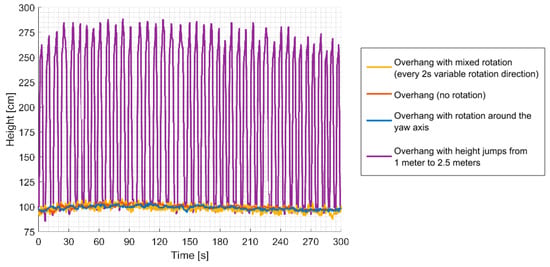
Figure 9.
Height measurement for four overhang variants.
In Figure 10, the recorded yaw angle of the device is shown. During the tests, when the yaw angle was constant (yaw = const), the device maintained this parameter with an accuracy of ±1°. The blue and yellow lines illustrate, respectively, a regular, constant rotation around its axis and a configuration with alternating right and left rotations.
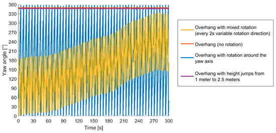
Figure 10.
Magnetometer reading for four overhang variants.
The current measurements taken during the tests are presented in Figure 11. In configurations 1 and 2, the current remained stable, with deviations of ±5%. In configuration 3, current spikes reaching up to ±30% were recorded, while in configuration 4, the deviations were as high as ±50% compared to the baseline values for configurations 1 and 2. In configuration 4, the current peaked during ascent but dropped significantly during descent. However, the average current values (around 19.12–19.39 A) do not indicate a significant increase in energy consumption across the configurations.
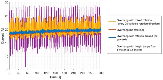
Figure 11.
Current measurement for four overhang variants.
Figure 12 shows the recorded voltage drop on the battery. After 5 min of measurement, the difference was 0.2 V between the experiments with height jumps and overhang with rotation around the yaw axis.
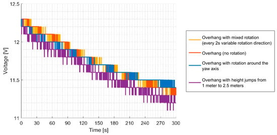
Figure 12.
Measured battery voltage for four overhang variants.
The last figure in this measurement series shows how much energy in mAh was consumed during the flight (Figure 13). The least energy was consumed for configuration 1, where the device did not rotate. Continuous rotation of the device (configuration 2) and height jumps to 2.5 m required 1% more energy. An additional 0.31% more energy was consumed in configuration 4, which involved continuous changes in direction. The graphs clearly show that when the UAV ascends to 2.5 m, the current spikes sharply—a typical effect caused by the increased energy demand required to overcome gravity. The rise in altitude necessitates the supply of more power in a short amount of time. However, the milliamp-hour (mAh) graph shows no significant increase in energy consumption over a longer period. This might suggest that despite the sharp current spikes during ascent, the system recovers some energy as the device descends. This is reflected by the relatively low current consumption during the descent phase.
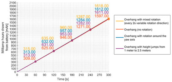
Figure 13.
Energy consumption for four overhang variants.
It can, therefore, be concluded that during ascent, the drone stores energy in the form of potential energy (depending on altitude), which it can later convert into kinetic energy during descent. Although the current temporarily increases, the total energy consumption over time remains similar to other experiments, as some energy used to increase the high is recovered during the descent process.
3.2. Circular Movement with a 2-M Diameter at a Constant Speed
In Figure 14, the measurement of UAV altitude during a flight along a circle of a 2 m diameter is presented. The recorded deviations are mostly due to the measurement methodology—the device tilting caused the sensor to measure the distance to the ground at an angle, leading to inaccuracies during movement. Additionally, the mats used in the experiment were waving, which also affected the results. Nevertheless, the vision system did not record deviations greater than 10 cm.

Figure 14.
Height measurement for three overhang variants.
The magnetometer readings during three flight configurations are shown in Figure 15. The green line illustrates the measurements for the first configuration, which involved no rotation. A constant value indicates no rotation, meaning the device only used the pitch and roll axes for control. In the second and third configurations, where the device was supposed to rotate around the yaw axis at a frequency of 8 rotations per minute, corresponding changes in the magnetometer readings were recorded.
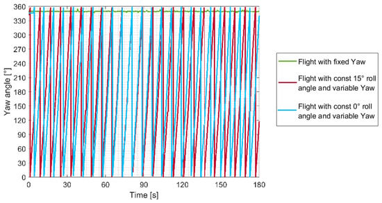
Figure 15.
Magnetometer reading for three overhang variants.
In Figure 16, the recorded current values during three different flight configurations are shown. The average current values were: for fixed yaw—18.8785 A, for continuous yaw adjustment—18.7733 A, and for continuous yaw adjustment and side tilt—17.9333 A. The results indicate that in the third configuration, the power consumption is significantly lower, suggesting a reduced system load in this configuration.
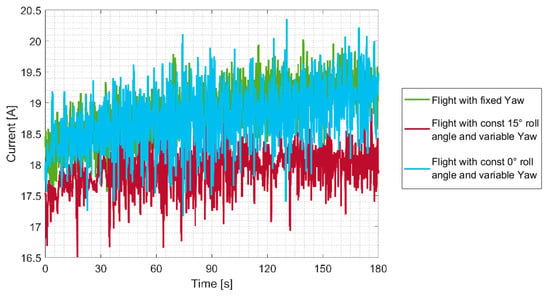
Figure 16.
Current measurement for three overhang variants.
The battery voltage change during flight is shown in Figure 17. In the third flight configuration, the voltage drop was 0.2 V lower than in the first and second configurations, which may indicate a reduced system load or better energy efficiency during this configuration. The energy consumption after 3 min of flight is presented in Figure 18. The device in configurations 1 and 2 used a comparable amount of energy, which is also visible in the current and voltage graphs. However, it is worth noting that the third configuration required 4.57% less energy to complete the task, suggesting better energy efficiency.
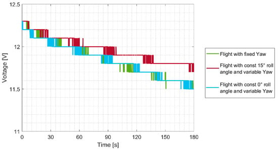
Figure 17.
Measured battery voltage for three overhang variants.
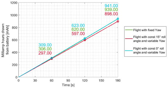
Figure 18.
Energy consumption for three overhang variants.
A comparison between hovering (without rotation) and flight (without rotation) indicates a slight difference in energy consumption—the 5 mAh difference after 3 min of flight is marginal (Figure 19). The other measurements differ by about 1–2%. Only one set of measurements stands out: flight with simultaneous variable pitch, roll, and yaw angles. Despite the device performing maneuvers, it required 5–7% less energy to execute this maneuver than hovering. During the tests, it was also observed that the drone was quieter in this configuration compared to other maneuvers. However, this observation requires further investigation.
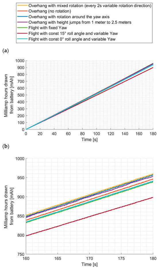
Figure 19.
Energy consumption for all maneuver and movement variants: (a) total measurement, (b) last sector.
4. Conclusions and Future Work
The research presented in this paper demonstrated clear relationships between UAV flight configuration, energy consumption, stability, and maneuver efficiency. Experimental measurements confirmed that specific combinations of roll, pitch, and yaw angles significantly influence the overall power demand of the propulsion system.
- Impact of Flight Configuration on Energy Consumption
The obtained results indicate that different control configurations directly affect energy consumption. A comparison between hovering without rotation and circular flight without rotation revealed only a marginal difference of approximately 5 mAh over a three-minute flight, corresponding to an energy variation of about 1–2%. However, when the UAV performed maneuvers involving simultaneous changes in roll, pitch, and yaw angles, the total energy consumption was reduced by 5–7%. This suggests that well-coordinated dynamic maneuvers can be more energy-efficient than static flight, as the aerodynamic forces are distributed more evenly across the propulsion units.
- Energy Characteristics of Hovering
Contrary to common assumptions, hovering is not the most energy-efficient flight condition for a multirotor UAV. Although hovering offers maximum stability and minimal aerodynamic disturbance, it requires continuous motor thrust adjustments to counteract small airflow and orientation variations. This leads to a relatively constant but non-negligible energy demand. In contrast, controlled dynamic maneuvers, such as coordinated rotation or banked flight, distribute aerodynamic forces more evenly across the propellers, resulting in slightly lower total energy consumption.
- Efficiency of Ascending and Descending
During ascent, the UAV consumed noticeably more power as it worked against gravity, while during descent, the current decreased and a partial recovery of kinetic energy was observed. On average, however, total energy expenditure remained close to that recorded for hovering. This indicates that the system effectively utilizes the principle of energy conservation, converting potential energy gained during ascent into kinetic energy during descent.
Overall, the results demonstrate that UAV control configuration has a measurable impact on energy efficiency. Proper coordination of yaw, roll, and pitch angles can significantly reduce energy demand, especially during dynamic maneuvers. These findings have practical relevance for optimizing autonomous flight algorithms and extending operational endurance in multirotor UAVs.
Future research will focus on optimizing UAV control algorithms for maneuvers involving variable pitch, roll, and yaw angles, which may lead to further energy savings, particularly in autonomous flight missions. It is also planned to evaluate the scalability of the obtained results for other UAV classes and propulsion configurations. In addition, future experiments will analyze the influence of parameters such as propeller geometry, thrust power, and total weight on overall energy consumption and flight efficiency. These studies will extend the current findings and provide a broader foundation for optimizing UAV control strategies.
Funding
This research received no external funding.
Data Availability Statement
The original contributions presented in this study are included in this article. Further inquiries can be directed to the author.
Conflicts of Interest
The author declares no conflict of interest.
References
- Lalrochunga, D.; Parida, A.; Choudhury, S. Systematic review on capacity building through renewable energy enabled IoT–Unmanned Aerial Vehicle for smart agroforestry. Clean. Circ. Bioecon. 2024, 8, 100094. [Google Scholar] [CrossRef]
- Boursianis, A.D.; Papadopoulou, M.S.; Diamantoulakis, P.; Liopa-Tsakalidi, A.; Barouchas, P.; Salahas, G.; Karagiannidis, G.; Wan, S.; Goudos, S.K. Internet of Things (IoT) and agricultural unmanned aerial vehicles (UAVs) in smart farming: A comprehensive review. Internet Things 2022, 18, 100187. [Google Scholar] [CrossRef]
- Ampatzidis, Y.; Partel, V.; Costa, L. Agroview: Cloud-based application to process, analyze and visualize UAV-collected data for precision agriculture applications utilizing artificial intelligence. Comput. Electron. Agric. 2020, 174, 105457. [Google Scholar] [CrossRef]
- Velusamy, P.; Rajendran, S.; Mahendran, R.K.; Naseer, S.; Shafiq, M.; Choi, J.-G. Unmanned aerial vehicles (UAV) in precision agriculture: Applications and challenges. Energies 2022, 15, 217. [Google Scholar] [CrossRef]
- Canicattì, M.; Vallone, M. Drones in vegetable crops: A systematic literature review. Smart Agric. Technol. 2024, 7, 100396. [Google Scholar] [CrossRef]
- Chang, C.Y.; Zhou, R.; Kira, O.; Marri, S.; Skovira, J.; Gu, L.; Sun, Y. An unmanned aerial system (UAS) for concurrent measurements of solar-induced chlorophyll fluorescence and hyperspectral reflectance toward improving crop monitoring. Agric. For. Meteorol. 2020, 294, 108145. [Google Scholar] [CrossRef]
- Kim, S.J.; Lim, G.J. Drone-aided border surveillance with an electrification line battery charging system. J. Intell. Robot. Syst. 2018, 92, 657–670. [Google Scholar] [CrossRef]
- Zhu, Y.; Yan, Y.; Dai, A.; Dai, H.; Zhang, Y.; Zhang, W.; Wang, Z.; Li, J. UAV-MSSH: A novel UAV photogrammetry-based framework for mining surface three-dimensional movement basin monitoring. Measurement 2025, 242 Pt B, 115944. [Google Scholar] [CrossRef]
- Khalil, A.; Jaradat, M.; Mukhopadhyay, S.; Abdel-Hafez, M. Autonomous control of a hybrid rolling and flying caged drone for leak detection in HVAC ducts. IEEE/ASME Trans. Mechatron. 2023, 29, 366–378. [Google Scholar] [CrossRef]
- López Peña, F.; Deibe Díaz, Á.; Orjales, F.; Losada Pita, J. A UAV system for visual inspection and wall thickness measurements in ship surveys. Measurement 2024, 238, 115262. [Google Scholar] [CrossRef]
- Li, A.; Hansen, M.; Zou, B. Traffic management and resource allocation for UAV-based parcel delivery in low-altitude urban space. Transp. Res. Part C Emerg. Technol. 2022, 143, 103808. [Google Scholar] [CrossRef]
- Kim, S.Y.; Kwon, D.Y.; Jang, A.; Ju, Y.K.; Lee, J.-S.; Hong, S. A review of UAV integration in forensic civil engineering: From sensor technologies to geotechnical, structural and water infrastructure applications. Measurement 2024, 224, 113886. [Google Scholar] [CrossRef]
- Mishra, D.; Tiwari, M.K. Integrated truck drone delivery services with optimal charging stations. Expert Syst. Appl. 2024, 254, 124254. [Google Scholar] [CrossRef]
- Szywalski, P.; Waindok, A.; Tomczuk, B. Implementation of a drones group in the area of extra high voltage grids. Przegląd Elektrotechniczny 2020, 96, 51–54. [Google Scholar] [CrossRef]
- Congress, S.S.C.; Puppala, A.J.; Escamilla, J.; Jaladurgam, R.; Kumar, P. Transportation bridge infrastructure asset condition monitoring using uncrewed aerial vehicles (UAVs). Transp. Geotech. 2024, 47, 101268. [Google Scholar] [CrossRef]
- Szywalski, P.; Waindok, A. Practical aspects of design and testing unmanned aerial vehicles. Acta Mech. Autom. 2020, 14, 50–58. [Google Scholar] [CrossRef]
- Tian, W.; Liu, L.; Zhang, X.; Shao, J. Flight trajectory and energy management coupled optimization for hybrid electric UAVs with adaptive sequential convex programming method. Appl. Energy 2024, 364, 123166. [Google Scholar] [CrossRef]
- Tang, D.Y.; Gong, M.T.; Yu, J.S.; Li, X. A power transfer model-based method for lithium-ion battery discharge time prediction of electric rotatory-wing UAV. Microelectron. Reliab. 2020, 114, 113832. [Google Scholar] [CrossRef]
- Liu, X.; Zhao, D.; Oo, N.L. Comparison studies on aerodynamic performances of a rotating propeller for small-size UAVs. Aerosp. Sci. Technol. 2023, 133, 108148. [Google Scholar] [CrossRef]
- Yıldırım, Ş.; Çabuk, N.; Bakırcıoğlu, V. Experimentally flight performances comparison of octocopter, decacopter and dodecacopter using universal UAV. Measurement 2023, 213, 112689. [Google Scholar] [CrossRef]
- De Wagter, C.; Remes, B.; Smeur, E.; van Tienen, F.; Ruijsink, R.; van Hecke, K.; van der Horst, E. The NederDrone: A hybrid lift, hybrid energy hydrogen UAV. Int. J. Hydrogen Energy 2021, 46, 16003–16018. [Google Scholar] [CrossRef]
- Hong, T.-K.; Lin, C.-Y.; Lin, H.-J.; Ruseno, N. Taiwan solar-powered UAV flight endurance record. Drone Syst. Appl. 2024, 12, 1–14. [Google Scholar] [CrossRef]
- Szywalski, P.; Waindok, A. Algorithm for planning, generating and simulating trajectories for a group of drones. In Proceedings of the 2020 International Conference on Mechatronic Systems and Materials (MSM), Bialystok, Poland, 1–3 July 2020; IEEE: Piscataway, NJ, USA, 2020. [Google Scholar] [CrossRef]
- Aslan, M.F.; Durdu, A.; Sabanci, K. Goal distance-based UAV path planning approach, path optimization and learning-based path estimation: GDRRT*, PSO-GDRRT* and BiLSTM-PSO-GDRRT*. Appl. Soft Comput. 2023, 137, 110156. [Google Scholar] [CrossRef]
- Kelner, J.M.; Burzynski, W.; Stecz, W. Modeling UAV swarm flight trajectories using rapidly-exploring random tree algorithm. J. King Saud Univ.-Comput. Inf. Sci. 2024, 36, 101909. [Google Scholar] [CrossRef]
- Chen, J.; Li, W.; Sha, Y.; Wang, Y.; Zhang, Z.; Li, S.; Wang, C.; Ma, S. Autonomous battery-changing system for UAV’s lifelong flight. Biomim. Intell. Robot. 2023, 3, 100104. [Google Scholar] [CrossRef]
- Vichitkunakorn, P.; Emde, S.; Masae, M.; Glock, C.H.; Grosse, E.H. Locating charging stations and routing drones for efficient automated stocktaking. Eur. J. Oper. Res. 2024, 316, 1129–1145. [Google Scholar] [CrossRef]
- Ahmadian, N.; Lim, G.J.; Torabbeigi, M.; Kim, S.J. Smart border patrol using drones and wireless charging system under budget limitation. Comput. Ind. Eng. 2022, 164, 107891. [Google Scholar] [CrossRef]
- Tian, W.; Liu, L.; Zhang, X.; Shao, J.; Ge, J. A coordinated optimization method of energy management and trajectory optimization for hybrid electric UAVs with PV/fuel cell/battery. Int. J. Hydrogen Energy 2024, 50 Pt B, 1110–1121. [Google Scholar] [CrossRef]
- Milutinović, D.; Casbeer, D.W.; Rasmussen, S. A switching composition of horizontal and vertical controllers for a UAV to reach a 3D waypoint. IFAC-PapersOnLine 2023, 56, 13–18. [Google Scholar] [CrossRef]
Disclaimer/Publisher’s Note: The statements, opinions and data contained in all publications are solely those of the individual author(s) and contributor(s) and not of MDPI and/or the editor(s). MDPI and/or the editor(s) disclaim responsibility for any injury to people or property resulting from any ideas, methods, instructions or products referred to in the content. |
© 2025 by the author. Licensee MDPI, Basel, Switzerland. This article is an open access article distributed under the terms and conditions of the Creative Commons Attribution (CC BY) license (https://creativecommons.org/licenses/by/4.0/).