1. Introduction
The switched reluctance motor (SRM) [
1,
2] is a double salient machine having a simple magnetic structure. It has only concentrated windings on the stator and without any coil winding or permanent magnet on the rotor, resulting in cost savings for the manufacturing process. Other advantages of SRM include high starting torque, fault tolerant, high efficiency over wide speed range and broad choice of converters depending on the application requirements; these make SRM an attractive alternative to conventional drive in numerous applications.
Many modern applications require higher efficiency and higher performance machines with reducing production cost. The challenge issue of SRM design techniques is to increase torque density while minimizing torque ripple, as these are major disadvantages of SRMs when compared to permanent–magnet (PM) motors. Most of the design methods are directly implemented via the design of motor geometries such as stator/rotor pole arc, stator/rotor pole shape, air gap, and stack length. To reduce the manufacturing cost, research work in [
3] introduced the optimization algorithm for SRM design to achieve a maximum torque at the minimum mass of the motor. The recent optimization design technique for finding the maximum torque density of 12/8 SRM was revealed in [
4]. This algorithm, based on the Grey Wolf Optimizer (GWO), can increase torque by 120% at the same outer value as the original design.
Changing winding arrangements is a simple method that does not require the machine structure to be redesigned, and a substantial increase in efficiency or performance can be achieved. For example, with a fully-pitched winding arrangement, as reported in [
5,
6,
7], torque capability can be increased by over 30%, resulting in higher efficiency than the conventional winding arrangement. The fully-pitched winding, which can operate with either unipolar or bipolar operation, uses the mutual-coupling among the phases for torque production and enhancement of torque density. In [
8,
9], an analysis, design, and SRM operation of the fractionally-pitched winding arrangement that also utilizes the mutual–coupling between phases are discussed. However, the fractionally-pitched winding is suitable for bipolar operation rather than unipolar operation. Another investigation on winding arrangements [
10,
11] uses finite element analysis to study short- and long-flux paths using single-phase and double-phase excitation for a three-phase 12/8 SRM; the studies also reveal that the maximum torque can be increased.
The flux reversal has a significant impact on the core loss of the SRM. Research on reducing flux reversal, such as [
12,
13,
14,
15,
16], was implemented by modifying the shape of the stator. In this paper, the method to reduce the flux reversal will be discussed based on the winding arrangement.
The objective of this paper is to investigate the winding arrangements of a three-phase 12/8 SRM under unipolar operation by considering the torque density comparison based on the same conduction loss, including the core loss effects, the total winding weights, and torque ripple of different winding arrangements. The simple method, which is the flux reversal pattern, for evaluating the core loss of the stator in each winding arrangement is introduced. Furthermore, the winding selection procedure for a three-phase 12/8 SRM to achieve high torque density, low torque ripple, and cost-saving for manufacturing is described. The finite element program (JMAG) and PC–SRD software are used mainly for the calculation of the torque density (static and dynamic), core loss, and structure of winding; winding weight, slot–fill factor, etc.
2. Winding Arrangement
2.1. Short-Pitched Winding
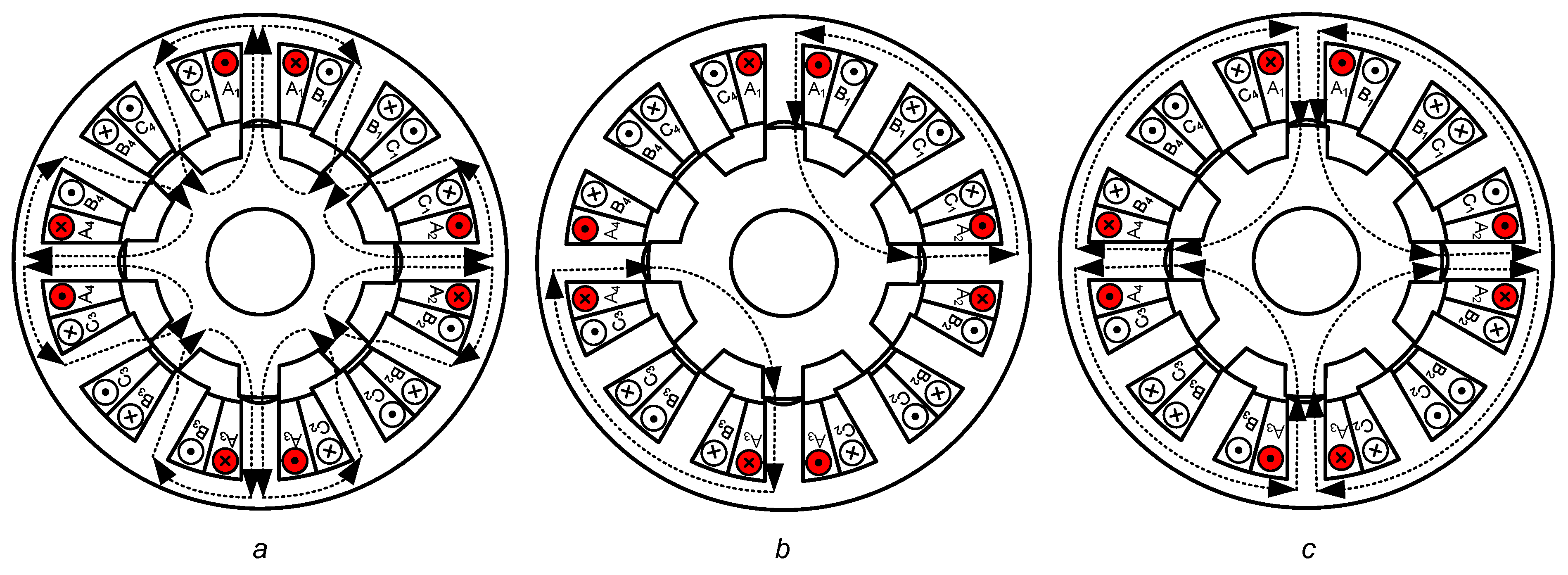
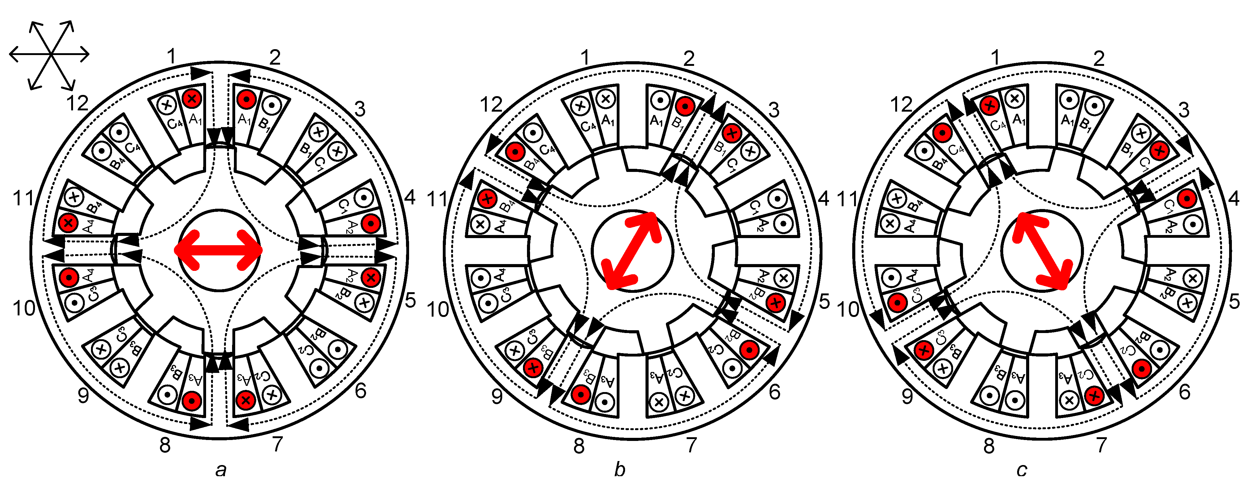
Figure 1 shows three diagrams of the short-pitched winding configuration and flux paths of the three-phase 12/8 SRM when a single phase (phase A) is excited with unipolar operation.
For the short-pitched winding, each coil is wound around a single stator pole. The winding’s polarities are arranged in the stator to give a magnetic pole when each phase is excited, resulting in the stator poles acting as a north (N) or south (S) magnetic pole, which is the main cause of magnetic–flux path direction. The 12/8 SRM’s winding polarities of short-pitched winding are modified to change the magnetic poles. In a particular phase,
Figure 1a shows the magnetic–flux paths when the sequential magnetic poles are the same, e.g., N–N–N–N and S–S–S–S. The sequential magnetic poles are such that two poles have the same polarity, e.g., S–N–N–S and N–S–S–N in
Figure 1b. The opposite of sequential magnetic poles, e.g., N–S–N–S and S–N–S–N, is shown in
Figure 1c.
The torque of SRM with short-pitched winding is produced due to the self-inductance variation. The mutual-inductance between the phase windings is ineffective and therefore neglected, resulting in
where the subscripts
a,
b, and
c denote the phase;
i,
L, and
are the phase current, self-inductance, and rotor position, respectively.
2.2. Fully-Pitched Winding
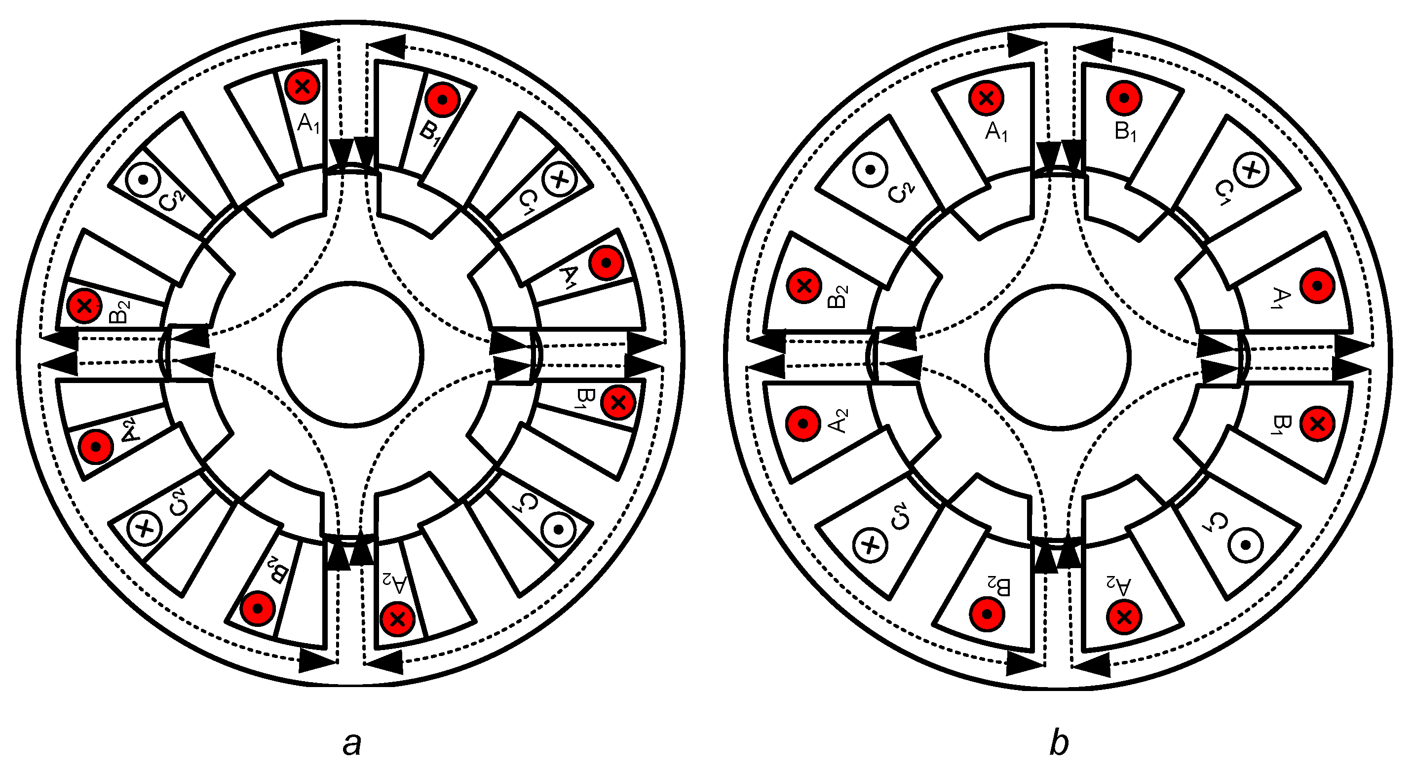
Three diagrams of the winding configuration and flux paths in a three-phase 12/8 SRM when two phases (phase A and B) are excited with unipolar operation are shown in
Figure 2. In the fully-pitched winding arrangement of the three-phase 12/8 SRM, each coil spans the surrounding three adjacent stator poles.
Figure 2a shows the fully-pitched winding diagram when the number of turns per pole is the same as the number of turns per pole of the short-pitched winding, while
Figure 2b shows the fully-pitched winding when it is wound with double the number of turns per pole of the short-pitched winding. The fully-pitched winding can operate with either unipolar (double-phase on at a time) or bipolar operation (double-phase on at a time and all three phases on at a time) [
5,
6,
7].
The torque of the fully-pitched winding is only produced due to the rate of change of the mutual-inductance (
M) among phases, and torque production can be achieved by exciting two phases simultaneously instead of only one phase in the short-pitched winding. The self-inductance of an individual phase is constant and has the same value as the maximum phase inductance at any rotor position. Therefore, the self-inductance of the fully-pitched winding is independent of the rotor position and is ineffective for torque production. The torque equation of the fully-pitched winding can be expressed by
3. Characteristics of the Winding Arrangement
3.1. Winding Weight and Comparison Based on Equal Conduction Loss
Table 1 shows the dimensions of the three-phase 12/8 SRM.
Table 2 shows the winding details of each winding configuration. The number of turns per pole of the short-pitched winding and fully-pitched winding 1 is the same, but it doubles in the fully-pitched winding 2. The number of windings of the short-pitched winding for the three-phase 12/8 SRM generally is the same as the number of stator poles, at 12 coils, as it is a concentrated winding, while the number of windings in fully pitched is decreased to six coils as it is a distributed winding. In terms of the slot-fill factor, which is the ratio of the actual cross–section of copper in a stator slot to the total stator slot area, the fully-pitched winding 1 has the lowest slot–fill factor, while other winding arrangements have the same slot-fill factor.
The total winding weight of the fully-pitched winding 2 is the highest at 9.0 kg, while the total weight of windings in the fully-pitched winding 1 is the lowest at 4.5 kg. The slot-fill factor, total weight of windings, and phase resistance of each winding arrangement are shown in
Table 3. The total winding weight of all short-pitched winding arrangements is the same at 5.1 kg. The fully-pitched winding 2 has the highest phase resistance value.
In the static machine test, it was thought fair to compare the various designs on the assumption of equal overall winding loss in each situation. Obviously, iron loss will be a key issue in the rotating machine: the influence of magnetic flux reversals on iron loss is explored in a subsequent section, but for a machine rotating at low speed, a comparison based on equal winding loss is sufficient. The winding loss per phase equation in the short-pitched winding SRM is given in
It is assumed that each phase conducts approximately one-third of an electrical cycle. Similarly, in the fully-pitched winding, it can be assumed that each phase conducts approximately two-thirds of one electrical cycle (two-phase excitation), and then the winding loss per phase equation in the fully-pitched winding SRM is given in (
4):
where the subscripts SP and FULL denote the short-pitched winding and fully-pitched winding, respectively;
I and
R are the conduction current and phase resistance, respectively.
To compare the five winding arrangements of a three-phase 12/8 SRM based on the same conduction loss for the same motor structure, the phase current of each winding arrangement is selected according to Equations (
3) and (
4) for the short-pitched and fully-pitched winding, respectively.
Table 4 shows the phase current of each winding configuration based on equal conduction loss. In the Finite Element Analysis (FEA) model, the phase current of each winding arrangement in
Table 4 is employed to simulate phase torque production.
The excitation methods under unipolar operation of the winding arrangement are shown in
Table 2. The short-pitched winding arrangements are excited with single-phase excitation at a time, while the fully-pitched winding arrangements are excited with double-phase excitation at a time.
3.2. Core Loss Based on Flux Reversals
The core losses consist of three parts: hysteresis loss, eddy current loss, and excess loss as shown in Equation (
5). The calculation of the core loss per unit volume (
) in the frequency domain is widely used for ferromagnetic material [
17] as it can be expressed as Equation (
6).
,
,
are the coefficients and
is the parameter of the core loss which are obtained from manufacturer data or experimental testing based on the curve–fitting method.
is the peak magnetic flux density and
f is the frequency. This equation is suitable for sinusoidal flux density waveforms, and it does not consider the minor loop in the main hysteresis loop.The frequency of the flux is determined by the phase switching frequency:
For SRM, the flux, which is distributed on the machine, is nonsinusoidal waveforms. Using the conventional equation may lead to large errors in the core loss calculation. Then, the core loss can be analyzed in the time domain [
18], which is suitable for the nonsinusoidal flux waveform, and it can be given by Equations (
7)–(
9):
is evaluated based on an equivalent elliptical loop and
is the numerical integration parameter as described in [
18]. From the core loss equation in the time domain, it can be seen that the main contributory impact of the core loss is the rate of change of the flux density with time;
. Modifying winding arrangement can change the direction of the flux path, which affects the flux density of the machine. The phenomenon of flux reversals in the stator core back is one of the causes that affects the variation of the flux density in the SRM [
14,
15,
16]. Therefore, minimizing the number of flux reversals occurring on the stator core back can decrease the core loss in SRM.
4. Selection of Winding Arrangement
4.1. Average Static Phase Torque
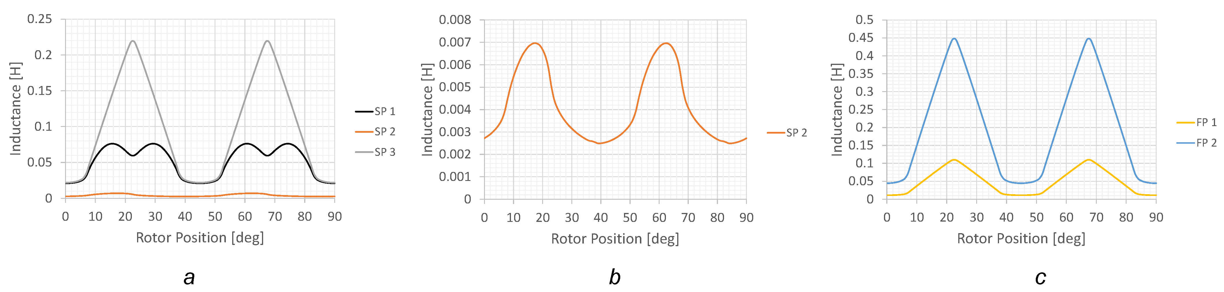
The effective static phase torque is generated according to the inductance profile of each winding arrangement, as shown in
Figure 3. The effective torque regions, which are the positive torque production zones of the three-phase 12/8 SRM, are 22.5 mechanical degrees.
Figure 4 shows the effective static phase torque profiles of each winding arrangement based on equal conduction loss. From
Figure 4, the fully-pitched winding 2, which is double-phase excitation, can produce the highest peak torque, at 44.08 Nm. For short-pitched winding arrangements, the short-pitched winding 1, which requires single phase excitation, can generate a peak torque of 35.18 Nm, but it produces negative torque at some position, and the short-pitched windings 2 and 3, which require single phase excitation, can generate a peak torque of 40.47 Nm and 41.4 Nm, respectively. In other fully-pitched winding arrangements, the fully-pitched winding 1, which uses double-phase excitation, can produce a peak torque of 29.3 Nm.
It can be observed in the short-pitched winding 1, which produces some negative torque due to its inductance profile having an early decrease slope before going to an aligned position at 22.5 degrees. The inductance profile of the fully-pitched winding 2 has a high slop caused by the high number of winding turns at 194 compared with other winding arrangements.
Table 5 lists the average value of the effective torque on the basis of the same conduction loss according to the torque profiles in
Figure 4. It is clear that the fully-pitched winding 2 can generate the highest average torque, while the short-pitched winding 1 can produce the lowest average torque.
4.2. Number of Flux Reversals on Stator Yoke
In this paper, the number of flux reversals is considered only on the stator yoke. The leakage flux is neglected. The yoke of the 12/8 SRM stator is divided into 12 segments. Each segment of the stator yoke experiences flux passing through it when the phase winding is excited. With different phases of winding excitation, the direction of the flux path in each stator yoke segment is varied.
As mentioned in the above discussion, the rate of change of the flux density with time significantly affects the core loss of the SRM stator. The number of flux reversals is one of the causes that involves the rate of change of the flux density on the stator core. In this paper, the number of flux reversals occurring on the stator yoke is observed by counting the number of changes in flux path direction in each stator segment when the phase windings are sequentially excited in one revolution. The number of flux reversals in the stator yoke can be given as
where
is the total number of flux reversals on the yoke of the stator,
is the number of changing flux path directions in each segment of the stator yoke when the phase windings are sequentially excited (A–B–C–A),
is the number of stator poles, and
n is the number of stator yoke segments.
Table 6 shows the number of flux reversals on the stator yoke in the different winding configurations. The short-pitched winding 3 and the fully-pitched winding have the highest number of flux reversals on the stator yoke at 288, while the short-pitched winding 2 does not have the number of flux reversals on the stator yoke. The short-pitched winding 1 still has a high number of flux reversals on the yoke of the stator at 240.
4.3. Consideration of Winding Selection
In terms of application, the ventilation exhaust fan for poultry farming requires a motor to run at a low rotational speed, have a high starting torque output, and be robust enough for the hard environment in a farming system. In terms of motor manufacturing, simple structure, no complexity in the assembly process, and low copper consumption for motor winding are the key factors for the candidate motor. From both points of view, SRM is a suitable choice for this application. Rated speed and load torque, including voltage range and converter topology of the SRM in this research, are shown in
Table 1.
The winding selection of SRM is determined by the characteristics of creating the high torque capacity to achieve a high–efficiency motor and using low copper, resulting in cost savings in the manufacture.
Table 2 and
Table 3 are used for considering the complexity of the winding assembly process and copper consumption in each winding configuration. The fully-pitched winding has a small number of coils at 6 coils, while the short-pitched winding has 12 coils. However, in terms of the manufacturing process, the short-pitched winding with a concentrated winding gives more advantages, such as the winding of a coil around a single–pole and short end–turn of coil compared with the fully-pitched (winding of a coil around three stator poles), which is similar to a distributed winding. Furthermore, the fully-pitched winding 2 uses more copper at 9 kg compared with any other type of winding arrangement.
To compare the torque performance, the ratio of the static phase torque per copper weight is applied for consideration as the stator and rotor core are the same weight. The static phase torque results based on equal conduction loss were obtained from the FEA model of SRM, which applied the phase current value in
Table 4 calculating based on equal conduction loss according to Equations (
3) and (
4) for the short-pitched and fully-pitched winding, respectively.
As shown in
Table 5, the ratio of the static phase torque per copper weight of the short-pitched windings 2 and 3 is high compared with other types of winding configuration. In terms of motor efficiency, the number of flux reversals of the short-pitched winding 2 is the lowest. On the other hand, the short-pitched winding 3 has a high number of flux reversals, as shown in
Table 6. Therefore, two candidates for the winding arrangement of the 12/8 SRM are the short-pitched windings 2 and 3. In the next analysis, the dynamic simulation analysis of each winding pattern will be discussed.
5. Dynamic Simulation
The dynamic simulation in this section is performed by JMAG finite element analysis software. The control parameters of the 12/8 SRM in the dynamic simulation are the same. The advance turn–on angle is 0 degrees, the conduction period is 22.5 degrees in the short-pitched winding, the conduction period is 30 in the fully-pitched winding, and the rotational speed is 500 r/min. A conventional hysteresis current control is applied and the maximum current is 9 A. The five winding configurations of the 12/8 SRM are simulated. Average torque and torque ripple are the essential considerations in this simulation.
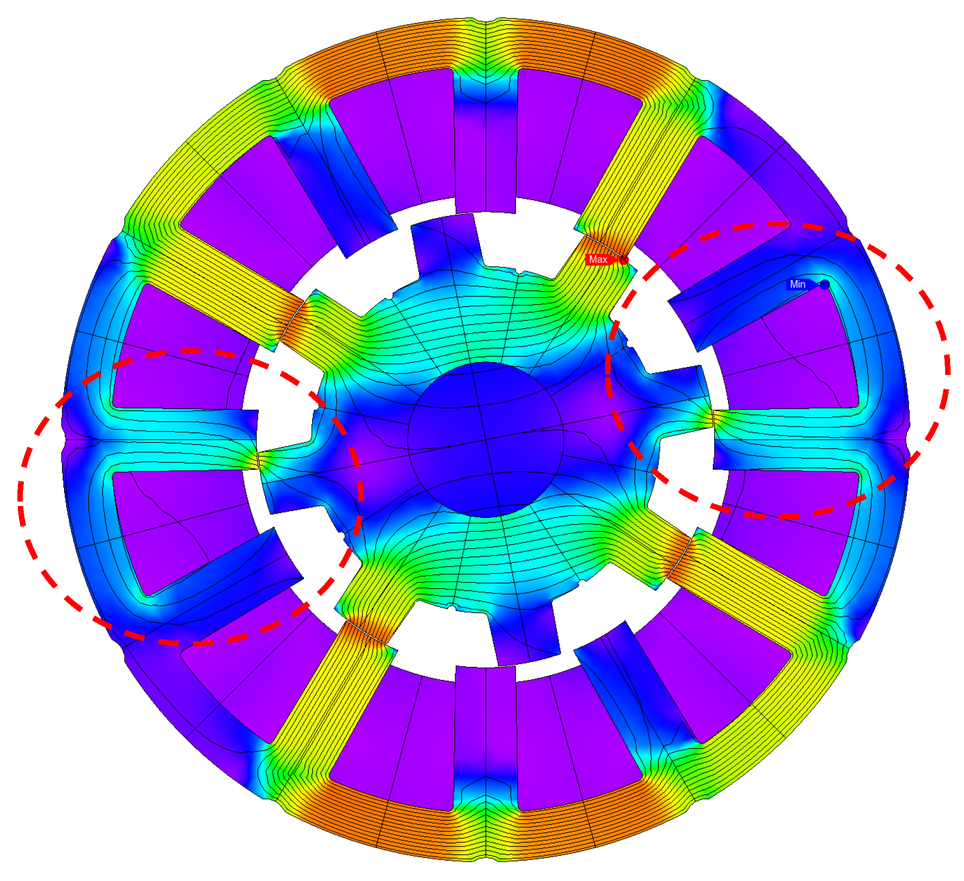
Figure 5 shows the flux density and flux path of the dynamic simulation. The result of the dynamic simulation is shown in
Figure 6 and
Figure 7 and comparative results in
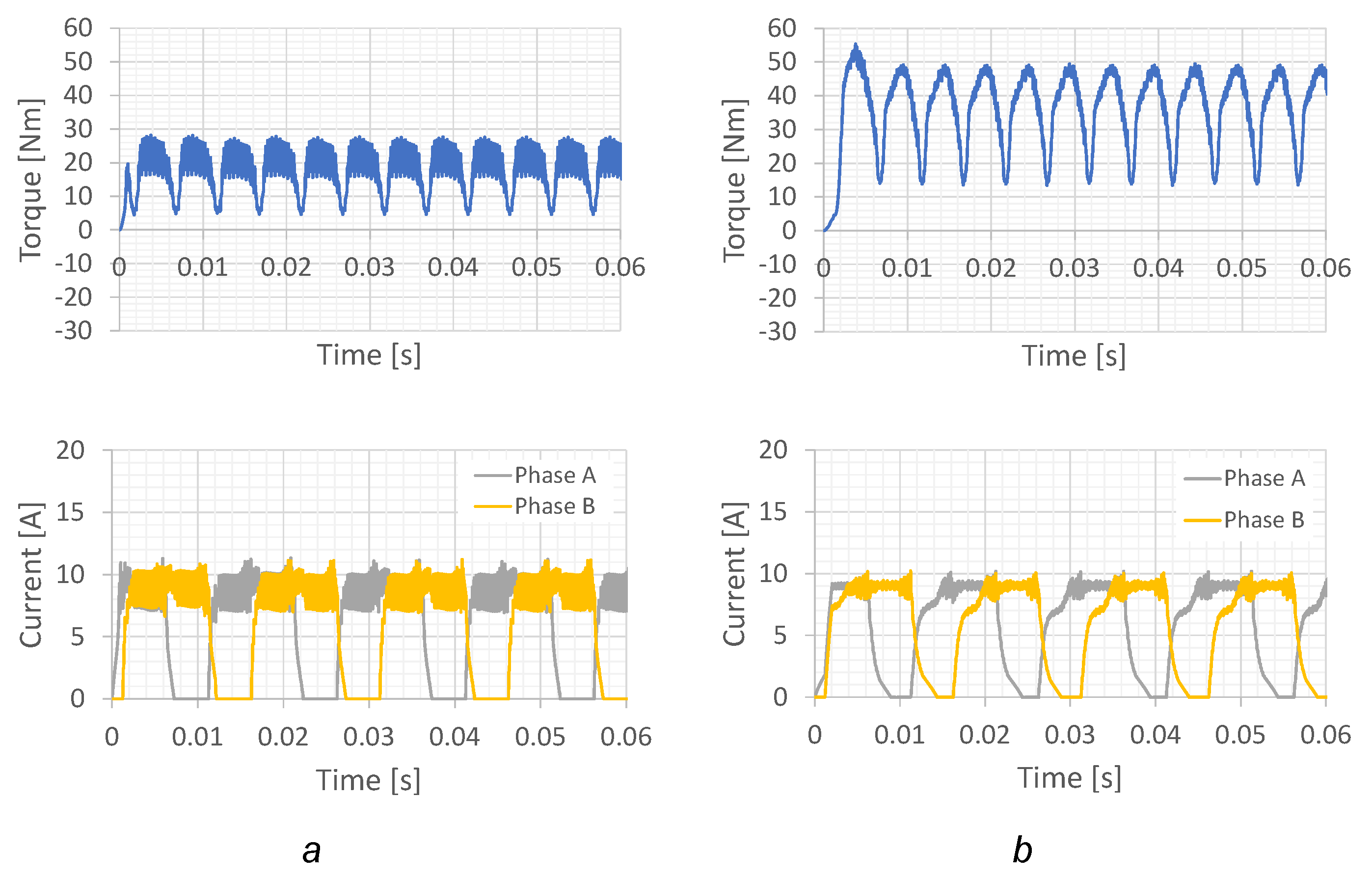
Table 7. The dynamic torque performance of the double-phase excitation of the fully-pitched winding is shown in
Figure 7. The torque ripple rate of the fully-pitched winding 1 and the fully-pitched winding 2 is 1.3 and 1.0, respectively. The average torque of the fully-pitched winding is the highest, at 36.55 Nm. However, with double-phase excitation and high phase resistance of the fully-pitched winding, it produces more copper losses compared with the other winding arrangements.
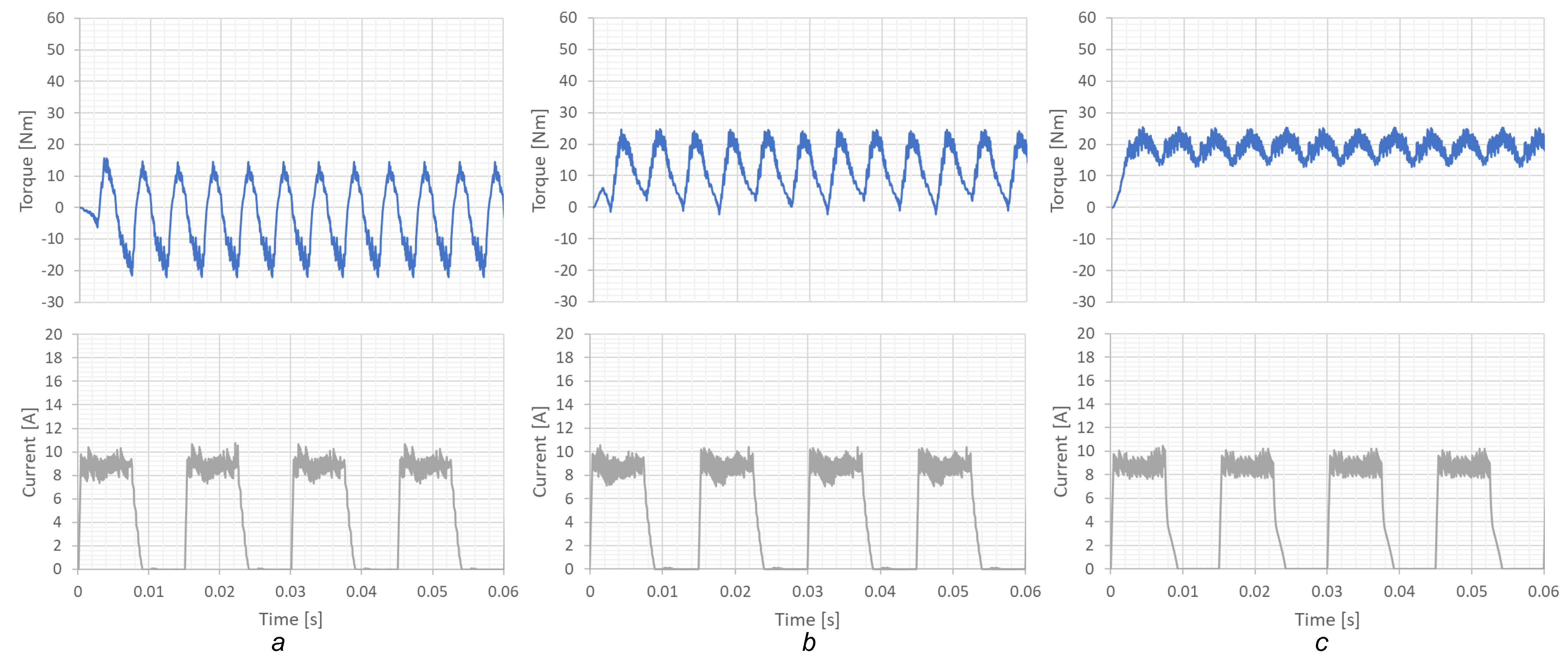
The dynamic torque performance of the single-phase excitation in
Figure 6 shows that the short-pitched winding 1 has a dramatically torque ripple rate of 10.28, and the average torque is lowest at 3.54 Nm. The short-pitched winding 2 has a torque ripple rate of 2.25 and the average torque decreases to 11.81 Nm. compared with the short-pitched winding 3 having a low torque ripple rate at 0.66 and average torque at 19 Nm. To describe this phenomenon,
Figure 5 shows the flux density and flux path of the short-pitched winding 2. The simulation results of the short-pitched winding 2 show that the leakage–flux paths appear on the adjacent stator poles when operating at high torque density. Therefore, the number of flux reversals in the stator yoke increases and generates more negative torque during phase commutation. The leakage–flux paths are shown in the red dot circle in
Figure 5. The short-pitched winding 2 has good torque performance and reduces the number of flux reversals when operating at low torque density, as was revealed in [
15]. For this reason, the average torque of the short-pitched winding 2 decreases, and the performance of the SRM drops to 76.63%, while the short-pitched winding 3 has a higher average torque and efficiency at 84.9%. However, the core loss of the short-pitched winding 2 is still lower than the short-pitched winding 3.
Table 8 reveals comparative results of dynamic simulation performance between short-pitched 2 and short-pitched 3 in terms of core loss at the stator and efficiency performance. For ventilation fan applications, the torque ripple has a significant impact on this application. A high torque ripple will lead to increased vibration and acoustic noise.
From the dynamic simulation results, it can be concluded that the short-pitched winding 3 is suitable for 12/8 SRM in terms of cost-saving, simple manufacturing process, torque ripple, and motor performance.
6. Flux Reversal Reduction
Although the short-pitched winding 3 gives a better performance for 12/8 SRM, the number of flux reversals of this winding configuration is still high. This paper proposes an analysis method that can reduce the flux reversals on the stator yoke. The short-pitched winding 3 is divided into Design A and Design B as follows:
In Design A, as shown in
Figure 8, the sequential magnetic poles in a clockwise direction are SNSN when excited phase A, NSNS when excited phase B, and NSNS when excited phase C.
In Design B, as shown in
Figure 9, the sequential magnetic poles in a clockwise direction are SNSN when excited phase A, NSNS when excited phase B, and SNSN when excited phase C.
The number of flux reversals in each segment of the stator yoke in the clockwise (A–B–C–A) and counter-clockwise (A–C–B–A) direction of Design A is illustrated in
Table 9. To calculate the total number of flux reversals in one revolution, Equation (
10) is used. The total number of flux reversals on the yoke of the stator is 192 in both directions (clockwise and counter–clockwise). Using the same procedure, Design B has a total number of flux reversals in one revolution of 288 in both directions (clockwise and counter–clockwise) as shown in
Table 10.
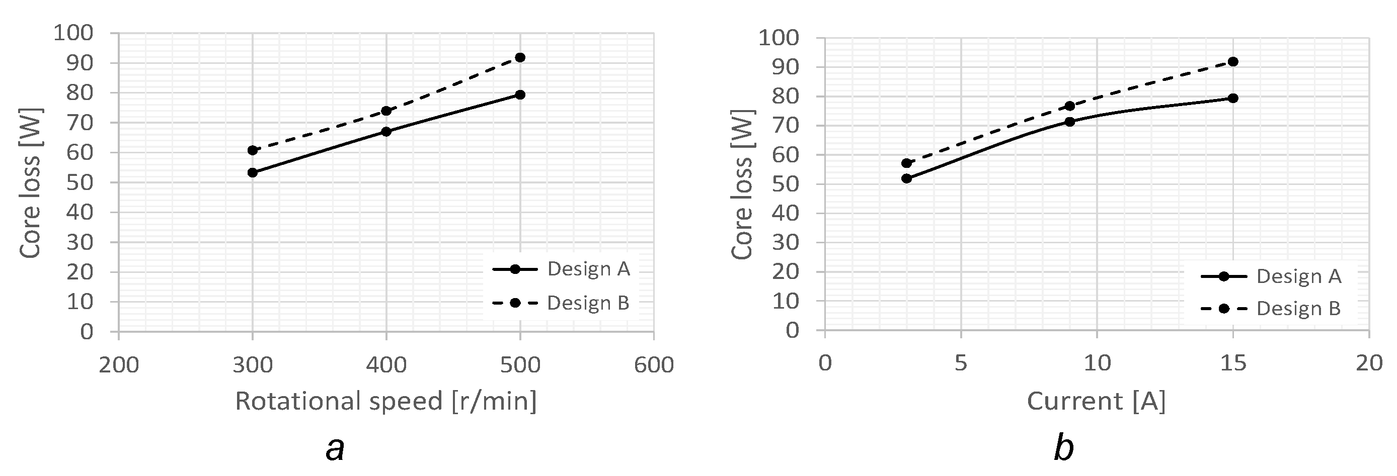
Table 11 reveals the results of the comparison of the short-pitched winding 3 with Designs A and B. The results show that the stator core loss is decreased in the short-pitched winding 3 with Design A.
Figure 10 shows the comparative results of core loss between short-pitched 3 Design A and Design B at each rotational speed and current level, respectively. It can be seen that Design A can reduce the core loss by around 7–9% at the rotational speed of 300–400 r/min with low current and around 10–13% at the rotational speed of 500 r/min with high current.
7. Experimental Results
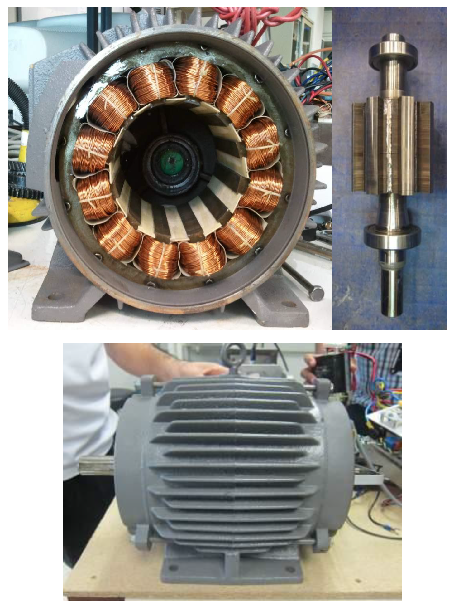
The three-phase 12/8 SRM prototype was built for ventilation fan applications using the existing induction motor frame size of 112 M, including cover, motor frame, and shaft according to the IEC standard. Therefore, the maximum outer diameter is 190 mm and the shaft diameter is 35 mm.
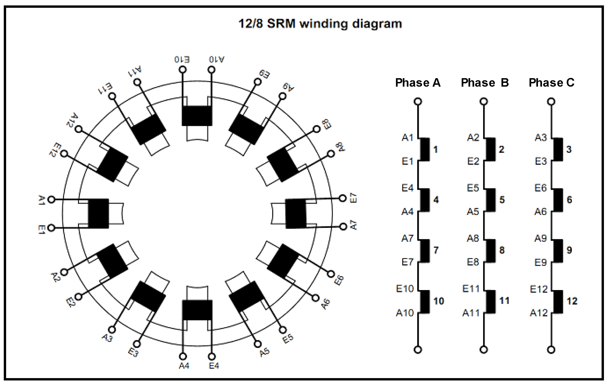
Figure 11 reveals the example of a single coil winding on the stator pole. The winding arrangement of the SRM prototype is the short-pitched winding 3 Design A, and the winding diagram is shown in
Figure 12.
Figure 13 illustrates the completed prototype of the 12/8 SRM.
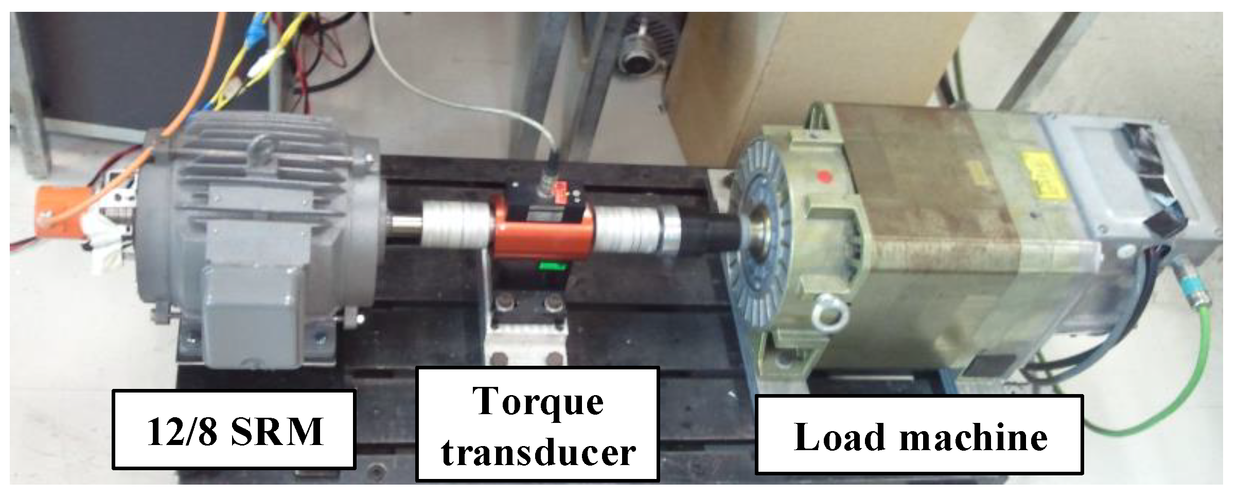
The experimental system setup is shown in
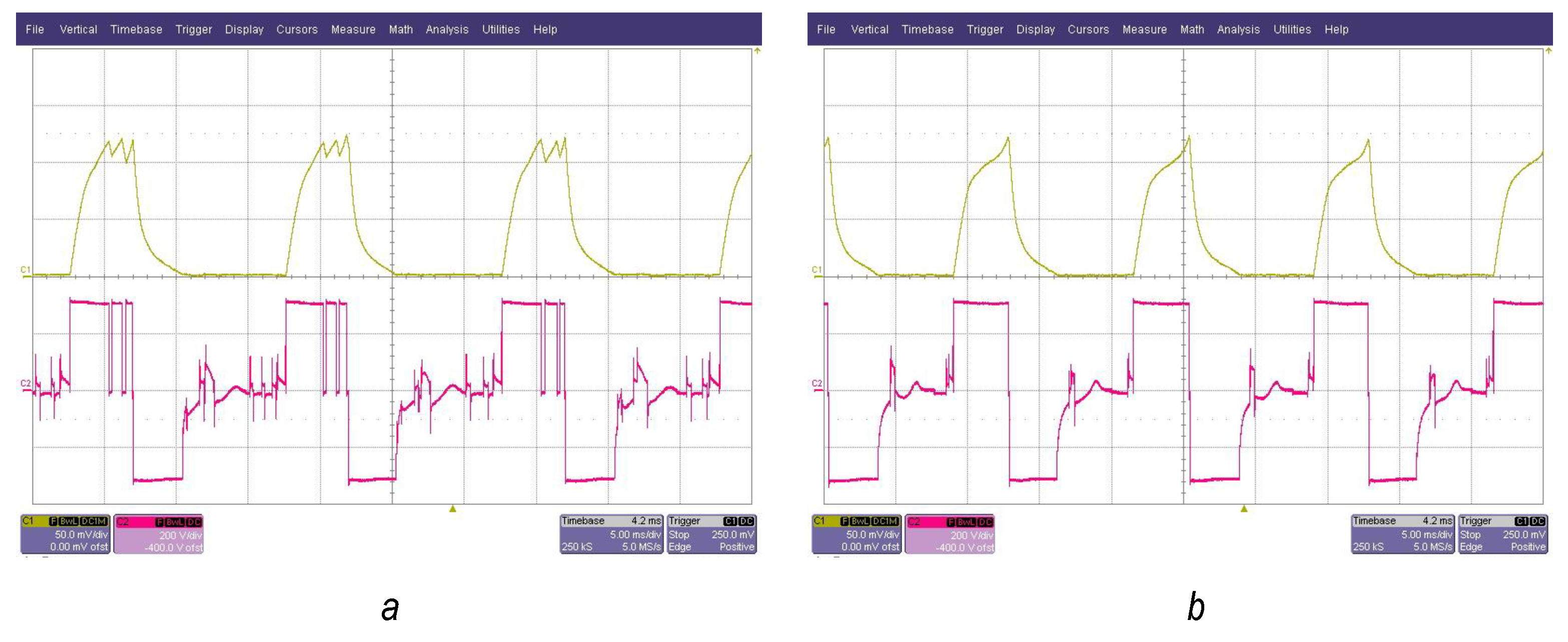
Figure 14. The rotor of the three-phase 12/8 SRM was connected to the rotor of the load machine (20 kW Siemens induction motor) via a flexible coupling and torque transducer. The turn-on and turn-off angles of SRM are 0 and 22.5 deg. The DC link voltage was 310 V. The experimental test was implemented at 500 r/min. The rated load torque output of 19.4 Nm of the load machine was applied to the 12/8 SRM. The current and voltage waveform of the experimental test are shown in
Figure 15a,b at the rotational speed of 600 r/min with load torque at 18.5 Nm of the load machine. It can be seen that the SRM prototype running at 600 r/min can carry less load torque due to the influence of voltage back electromotive force, which increases with rotational speed. Therefore, phase current cannot reach the level of the desired current, leading to low torque capability. However, when the phase current decreases, the loss of the copper also reduces. For this reason, the motor performance of 600 r/min gives high efficiency.
Figure 16 shows the experimental results of torque vs. speed and efficiency vs. speed curves with different rotational speeds between 300–1500 r/min. The maximum torque of the SRM prototype is 21.8 Nm at 300 r/min. At the rated speed of 500 r/min, the SRM prototype can carry torque at 19.4 of load torque which covers the desired rated torque, and the efficiency of the motor is 82.5%. The maximum efficiency of the SRM prototype can reach 83.1% at 600 r/min with 18.5 Nm of load torque.
The comparative results at rated conditions between the simulation model and experimental test are illustrated in
Table 12. The SRM prototype gives a torque output of 19.4 Nm close to the simulation model, which has 18.9 Nm. However, the efficiency of the SRM prototype decreased to 82.5%, while the simulation model could achieve 85.14%. In the experimental test, the maximum current of the hysteresis current control is higher than that of the simulation, so this will lead to an increase in the copper loss of the system. To achieve the rated torque of 19.0 Nm, the SRM prototype requires more phase current than that in the simulation model due to the imperfections during the manufacture and assembly process, such as errors in air gap length, non-uniform air gap, and eccentricity error, etc.
8. Conclusions
This research has introduced the criteria to consider for choosing the winding configuration of three-phase 12/8 SRM as follows:
In the analysis of the static characteristic: (1) the ratio value of static phase torque (based on equal conduction loss) per weight of copper winding needs to be considered for selecting winding configuration to produce high efficiency and cost-saving in the production process; (2) the number of flux reversals on the stator yoke of the SRM, winding configuration having a low number of flux reversals can reduce the core loss.
In the analysis of the dynamic characteristics, the torque ripple is the main parameter that each winding configuration needs to consider, especially since the torque ripple has a significant impact on the ventilation fan application.
The comparison of the winding arrangements for the same motor structure reveals that the total winding weight of the fully-pitched winding 2 is the highest because of the increased end windings. The comparison of the average torque results on the basis of equal conduction loss shows that the fully-pitched winding 2 with double-phase unipolar excitation and the short-pitched winding 3 with single phase unipolar excitation are effective for enhancing the torque density. The current level of the fully-pitched winding 2 has to be reduced to attain the same conduction loss where average output torque is still higher than any other winding arrangement.
The consideration of winding selection is discussed based on cost-saving, the complexity of the manufacturing process, and machine performance, including torque output and torque ripple. The short-pitched winding 3 gives significantly better performance in terms of the ratio of the static phase torque per copper weight compared with other winding configurations. For initial consideration of core loss in SRM, the counting of the number of flux reversals on the stator yoke is proposed. The simulation results confirm that minimizing the number of flux reversals in the stator yoke by modifying the winding polarities can decrease the core loss of the SRM. Finally, the 12/8 SRM prototype was built and tested (load test and characteristic test).
Author Contributions
Conceptualization, R.P. and K.T.; methodology, R.P. and K.T.; validation, R.P., S.K., P.J., P.S. and K.T.; formal analysis, R.P. and K.T.; investigation, R.P., P.S. and K.T.; resources, S.K., P.J. and P.S.; writing—original draft preparation, R.P.; writing—review and editing, R.P., S.K., P.J., P.S. and K.T.; visualization, R.P. and S.K.; supervision, K.T. All authors have read and agreed to the published version of the manuscript.
Funding
This research received no external funding.
Institutional Review Board Statement
Not applicable.
Informed Consent Statement
Not applicable.
Data Availability Statement
Not applicable.
Conflicts of Interest
The authors declare no conflict of interest.
Nomeclatures
| N | north magnetic pole |
| S | south magnetic pole |
| T | torque |
| i | phase current |
| rotor position |
| L | self-inductance |
| M | mutual-inductance |
| SP | short-pitched winding |
| FULL | fully-pitched winding |
| I | conduction current |
| R | phase resistance |
| core losses |
| hysteresis loss |
| eddy current loss |
| excess loss |
| hysteresis loss coefficient |
| eddy current loss coefficient |
| excess loss coefficient |
| | core loss parameter based on the curve-fitting method |
| peak magnetic flux density |
| B | magnetic flux density |
| evaluated value based on an equivalent elliptical loop [18] |
| numerical integration parameter [18] |
| total number of flux reversals on stator yoke |
| number of changing flux path direction in each segment of stator yoke |
| number of stator poles |
| n | number of stator yoke segments |
References
- Miller, T.J.E. Switched Reluctance Motors and Their Control; Magna Physics Publishing and Clarendon Press: Oxford, UK, 1993. [Google Scholar]
- Krishnan, R. Switched Reluctance Motor Drives: Modeling, Simulation, Analysis, Design, and Applications; CRC Press: Boca Raton, FL, USA, 2001. [Google Scholar]
- Widmer, J.D.; Martin, R.; Mecrow, B.C. Optimization of an 80-kW Segmental Rotor Switched Reluctance Machine for Automotive Traction. IEEE Trans. Ind. Appl. 2015, 51, 2990–2999. [Google Scholar] [CrossRef]
- Rahman, M.S.; Lukman, G.F.; Hieu, P.T.; Jeong, K.I.; Ahn, J.W. Optimization and Characteristics Analysis of High Torque Density 12/8 Switched Reluctance Motor Using Metaheuristic Gray Wolf Optimization Algorithm. Energies 2021, 14, 2013. [Google Scholar] [CrossRef]
- Mecrow, B. Fully pitched-winding switched-reluctance and stepping-motor arrangements. IEE Proc. B (Electr. Power Appl.) 1993, 140, 61–70. [Google Scholar] [CrossRef]
- Barrass, P.G.; Mecrow, B.C.; Clothier, A.C. Bipolar operation of fully-pitched winding switched reluctance drives. In Proceedings of the 1995 Seventh International Conference on Electrical Machines and Drives (Conf. Publ. No. 412), Durham, UK, 11–13 September 1995; pp. 252–256. [Google Scholar] [CrossRef]
- Mecrow, B.C. New winding configurations for doubly salient reluctance machines. IEEE Trans. Ind. Appl. 1996, 32, 1348–1356. [Google Scholar] [CrossRef]
- Li, Y.; Tang, Y. Switched reluctance motor drives with fractionally-pitched winding design. In Proceedings of the PESC97, Record 28th Annual IEEE Power Electronics Specialists Conference, Formerly Power Conditioning Specialists Conference 1970–71, Power Processing and Electronic Specialists Conference 1972, St. Louis, MO, USA, 27 June 1997; Volume 2, pp. 875–880. [Google Scholar] [CrossRef]
- Tang, Y. Switched reluctance motor with fractionally pitched windings and bipolar currents. In Proceedings of the Conference Record of 1998 IEEE Industry Applications Conference, Thirty-Third IAS Annual Meeting (Cat. No. 98CH36242), St. Louis, MO, USA, 12–15 October 1998; Volume 1, pp. 351–358. [Google Scholar] [CrossRef]
- Chen, H.; Song, Q. Windings arrangement of a three-phase switched reluctance machine. In Proceedings of the IEEE International Electric Machines and Drives Conference, IEMDC’03, Madison, WI, USA, 1–4 June 2003; Volume 3, pp. 1665–1668. [Google Scholar] [CrossRef]
- Pupadubsin, R.; Chayopitak, N.; Karukanan, S.; Champa, P.; Somsiri, P.; Tungpimolrut, K. Comparison of winding arrangements of three phase switched reluctance motor under unipolar operation. In Proceedings of the 2012 15th International Conference on Electrical Machines and Systems (ICEMS), Sapporo, Japan, 21–24 October 2012; pp. 1–4. [Google Scholar]
- Augustine, M.; Balaji, M.; Kamaraj, V. Characteristics Assessment of Switched Reluctance Motor with Segmented Rotor. In Proceedings of the 2019 IEEE 1st International Conference on Energy, Systems and Information Processing (ICESIP), Chennai, India, 4–6 July 2019; pp. 1–6. [Google Scholar] [CrossRef]
- Prabhu, S.; Balaji, M.; Kamaraj, V. Analysis of two phase switched reluctance motor with flux reversal free stator. In Proceedings of the 2015 IEEE 11th International Conference on Power Electronics and Drive Systems, Sydney, NSW, Australia, 9–12 June 2015; pp. 320–325. [Google Scholar] [CrossRef]
- Oh, S.; Krishnan, R. Two-Phase SRM With Flux-Reversal-Free Stator: Concept, Analysis, Design, and Experimental Verification. IEEE Trans. Ind. Appl. 2007, 43, 1247–1257. [Google Scholar] [CrossRef]
- Lobo, N.S.; Swint, E.; Krishnan, R. M-Phase N-Segment Flux-Reversal-Free Stator Switched Reluctance Machines. In Proceedings of the 2008 IEEE Industry Applications Society Annual Meeting, Edmonton, AB, Canada, 5–9 October 2008; pp. 1–8. [Google Scholar] [CrossRef]
- Seshadri, A.; Lenin, N.C. Review based on losses, torque ripple, vibration and noise in switched reluctance motor. IET Electr. Power Appl. 2020, 14, 1311–1326. [Google Scholar] [CrossRef]
- Bertotti, G. General properties of power losses in soft ferromagnetic materials. IEEE Trans. Magn. 1988, 24, 621–630. [Google Scholar] [CrossRef]
- Lin, D.; Zhou, P.; Fu, W.N.; Badics, Z.; Cendes, Z.J. A dynamic core loss model for soft ferromagnetic and power ferrite materials in transient finite element analysis. IEEE Trans. Magn. 2004, 40, 1318–1321. [Google Scholar] [CrossRef]
Figure 1.
Winding arrangement for single-phase excitation; (a) Short-pitched winding 1; (b) Short-pitched winding 2; and (c) Short-pitched winding 3.
Figure 1.
Winding arrangement for single-phase excitation; (a) Short-pitched winding 1; (b) Short-pitched winding 2; and (c) Short-pitched winding 3.
Figure 2.
Winding arrangement for double-phase excitation; (a) fully-pitched winding 1 and (b) fully-pitched winding 2.
Figure 2.
Winding arrangement for double-phase excitation; (a) fully-pitched winding 1 and (b) fully-pitched winding 2.
Figure 3.
Inductance profiles of a three-phase 12/8 SRM at different winding arrangements; (a) Short-pitched winding; (b) Short-pitched winding 2; and (c) Fully-pitched winding.
Figure 3.
Inductance profiles of a three-phase 12/8 SRM at different winding arrangements; (a) Short-pitched winding; (b) Short-pitched winding 2; and (c) Fully-pitched winding.
Figure 4.
Effective static torque of a three-phase 12/8 SRM at different winding arrangements on the basis of equal conduction loss.
Figure 4.
Effective static torque of a three-phase 12/8 SRM at different winding arrangements on the basis of equal conduction loss.
Figure 5.
Leakage-flux path of the short-pitched winding 2 when operates at high current densities.
Figure 5.
Leakage-flux path of the short-pitched winding 2 when operates at high current densities.
Figure 6.
Torque and current waveform (Phase A) for single-phase excitation; (a) Short-pitched winding 1; (b) Short-pitched winding 2; and (c) Short-pitched winding 3.
Figure 6.
Torque and current waveform (Phase A) for single-phase excitation; (a) Short-pitched winding 1; (b) Short-pitched winding 2; and (c) Short-pitched winding 3.
Figure 7.
Torque and current waveform for double-phase excitation; (a) Fully-pitched winding 1 and (b) Fully-pitched winding 2.
Figure 7.
Torque and current waveform for double-phase excitation; (a) Fully-pitched winding 1 and (b) Fully-pitched winding 2.
Figure 8.
Excitation pattern and flux-path of the short-pitched winding 3 in Design A; (a) Phase A is excited; (b) Phase B is excited; and (c) Phase C is excited.
Figure 8.
Excitation pattern and flux-path of the short-pitched winding 3 in Design A; (a) Phase A is excited; (b) Phase B is excited; and (c) Phase C is excited.
Figure 9.
Excitation pattern and flux-path of the short-pitched winding 3 in Design B; (a) Phase A is excited; (b) Phase B is excited; and (c) Phase C is excited.
Figure 9.
Excitation pattern and flux-path of the short-pitched winding 3 in Design B; (a) Phase A is excited; (b) Phase B is excited; and (c) Phase C is excited.
Figure 10.
Core loss of the short-pitched winding 3 Design A and Design B; (a) at different rotational speeds and (b) at different current levels.
Figure 10.
Core loss of the short-pitched winding 3 Design A and Design B; (a) at different rotational speeds and (b) at different current levels.
Figure 11.
One coil winding on the stator pole.
Figure 11.
One coil winding on the stator pole.
Figure 12.
Winding diagram of the 12/8 SRM prototype.
Figure 12.
Winding diagram of the 12/8 SRM prototype.
Figure 13.
Stator, rotor, and completed 12/8 SRM prototype.
Figure 13.
Stator, rotor, and completed 12/8 SRM prototype.
Figure 14.
Experimental test rig.
Figure 14.
Experimental test rig.
Figure 15.
Phase A current (Top) and voltage (Bottom) waveform of the 12/8 SRM prototype using SP 3 Design A winding configuration; (a) at 500 r/min with 19.4 Nm of load torque and (b) at 600 r/min with 18.5 Nm of load torque.
Figure 15.
Phase A current (Top) and voltage (Bottom) waveform of the 12/8 SRM prototype using SP 3 Design A winding configuration; (a) at 500 r/min with 19.4 Nm of load torque and (b) at 600 r/min with 18.5 Nm of load torque.
Figure 16.
Efficiency and torque at different rotational speeds.
Figure 16.
Efficiency and torque at different rotational speeds.
Table 1.
Details and dimensions of the 12/8 SRM.
Table 1.
Details and dimensions of the 12/8 SRM.
| Parameter | Value |
|---|
| Stator outer diameter [mm] | 190 |
| Stator inner diameter [mm] | 168 |
| Stator pole arc [mechanical degree] | 15 |
| Rotor pole arc [mechanical degree] | 16 |
| Shaft diameter [mm] | 35 |
| Air gap [mm] | 0.3 |
| Stack length [mm] | 120 |
| Wire diameter [mm] | 0.914 (SWG 20) |
| Number of strands | 2 |
| Rated speed [r/min] | 500 |
| Rated torque [Nm] | 19 |
| DC link voltage [V] | 310 |
| Converter topology | Asymmetric bridge |
Table 2.
Winding arrangement details.
Table 2.
Winding arrangement details.
| Winding Arrangement | Number of Turns per Pole | Number of Coils | Excitation Type |
|---|
| Short-pitched 1 | 97 | 12 | Single phase |
| Short-pitched 2 | 97 | 12 | Single phase |
| Short-pitched 3 | 97 | 12 | Single phase |
| Fully-pitched 1 | 97 | 6 | Double-phase |
| Fully-pitched 2 | 194 | 6 | Double-phase |
Table 3.
Electrical and mechanical details.
Table 3.
Electrical and mechanical details.
| Winding Arrangement | Slot-Fill Factor | Total Weight of Windings [kg] | Phase Resistance [] |
|---|
| Short-pitched 1 | 0.37 | 5.1 | 1.9 |
| Short-pitched 2 | 0.37 | 5.1 | 1.9 |
| Short-pitched 3 | 0.37 | 5.1 | 1.9 |
| Fully-pitched 1 | 0.18 | 4.5 | 1.7 |
| Fully-pitched 2 | 0.37 | 9.0 | 3.4 |
Table 4.
Phase winding current comparison for the same conduction loss.
Table 4.
Phase winding current comparison for the same conduction loss.
| Winding Arrangement | Phase Winding Current at the Same Conduction Loss [A] |
|---|
| Short-pitched 1, 2, 3 | 15 |
| Fully-pitched 1 | 11.27 |
| Fully-pitched 2 | 7.98 |
Table 5.
Average static torque at the same conduction loss.
Table 5.
Average static torque at the same conduction loss.
| Winding Arrangement | Static Torque [Nm] | Torque/Copper Weight [Nm/kg] |
|---|
| Short-pitched 1 | 9.8 | 1.9 |
| Short-pitched 2 | 19.6 | 3.8 |
| Short-pitched 3 | 21.6 | 4.2 |
| Fully-pitched 1 | 15.9 | 3.5 |
| Fully-pitched 2 | 23.4 | 2.6 |
Table 6.
Number of flux reversals in the stator yoke in 1 revolution.
Table 6.
Number of flux reversals in the stator yoke in 1 revolution.
| Winding Arrangement | Number of Flux Reversals |
|---|
| Short-pitched 1 | 240 |
| Short-pitched 2 | 0 |
| Short-pitched 3 | 288 |
| Fully-pitched 1 | 288 |
| Fully-pitched 2 | 288 |
Table 7.
Comparison of dynamic simulation performance.
Table 7.
Comparison of dynamic simulation performance.
| Winding Arrangement | Average Torque [Nm] | Torque Ripple Rate |
|---|
| Short-pitched 1 | 3.54 | 10.28 |
| Short-pitched 2 | 11.81 | 2.25 |
| Short-pitched 3 | 19.0 | 0.66 |
| Fully-pitched 1 | 17.12 | 1.30 |
| Fully-pitched 2 | 36.55 | 1.00 |
Table 8.
Comparison of motor performance between short-pitched 2 and short-pitched 3.
Table 8.
Comparison of motor performance between short-pitched 2 and short-pitched 3.
| | Short-Pitched 2 | Short-Pitched 3 |
|---|
| Average torque [Nm] | 11.81 | 19.0 |
| Torque ripple rate | 2.25 | 0.66 |
| Core loss at stator [W] | 37.67 | 38.44 |
| Efficiency [%] | 76.63 | 84.9 |
Table 9.
Number of flux reversals in Design A.
Table 9.
Number of flux reversals in Design A.
| Stator Yoke Sector | Flux-Linkage Direction (Clockwise) | No. of Reverse Direction (Clockwise) | Flux-Linkage Direction (Counter Clockwise) | No. of Reverse Direction (Counter Clockwise) |
|---|
| 1 | | 2 | | 2 |
| 2 | | 0 | | 0 |
| 3 | | 2 | | 2 |
| 4 | | 2 | | 2 |
| 5 | | 0 | | 0 |
| 6 | | 2 | | 2 |
| 7 | | 2 | | 2 |
| 8 | | 0 | | 0 |
| 9 | | 2 | | 2 |
| 10 | | 2 | | 2 |
| 11 | | 0 | | 0 |
| 12 | | 2 | | 2 |
| | Total | 16 | Total | 16 |
Table 10.
Number of flux reversals in Design B.
Table 10.
Number of flux reversals in Design B.
| Stator Yoke Sector | Flux-Linkage Direction (Clockwise) | No. of Reverse Direction (Clockwise) | Flux-Linkage Direction (Counter Clockwise) | No. of Reverse Direction (Counter Clockwise) |
|---|
| | | | |
|---|
| | | | |
|---|
| | | | | |
|---|
| | | | | |
|---|
| 1 | | 2 | | 2 |
| 2 | | 2 | | 2 |
| 3 | | 2 | | 2 |
| 4 | | 2 | | 2 |
| 5 | | 2 | | 2 |
| 6 | | 2 | | 2 |
| 7 | | 2 | | 2 |
| 8 | | 2 | | 2 |
| 9 | | 2 | | 2 |
| 10 | | 2 | | 2 |
| 11 | | 2 | | 2 |
| 12 | | 2 | | 2 |
| | Total | 24 | Total | 24 |
Table 11.
Comparison of winding performance short-pitched winding 3 Design A (SP 3 Design A) and short-pitched winding 3 Design B (SP 3 Design B).
Table 11.
Comparison of winding performance short-pitched winding 3 Design A (SP 3 Design A) and short-pitched winding 3 Design B (SP 3 Design B).
| | SP 3 Design A | SP 3 Design B |
|---|
| Average torque [Nm] | 18.9 | 19.0 |
| Torque ripple rate | 0.66 | 0.66 |
| Core loss at stator [W] | 36.36 | 38.44 |
| Efficiency [%] | 85.14 | 84.9 |
Table 12.
Experimental results.
Table 12.
Experimental results.
| | SP 3 Design A FEA | SP 3 Design A Exp |
|---|
| Average torque [Nm] | 18.9 | 19.4 |
| Efficiency [%] | 85.14 | 82.5 |
| Aligned inductance [mH] | 218.57 | 215.54 |
| Unaligned inductance [mH] | 21.86 | 27.37 |
| Publisher’s Note: MDPI stays neutral with regard to jurisdictional claims in published maps and institutional affiliations. |
© 2022 by the authors. Licensee MDPI, Basel, Switzerland. This article is an open access article distributed under the terms and conditions of the Creative Commons Attribution (CC BY) license (https://creativecommons.org/licenses/by/4.0/).


 ,
, 


