Abstract
The replacement of conventional generation by power electronics-based generation changes the dynamic characteristics of the power system. This results in, among other things, the increased susceptibility to subsynchronous oscillations (SSO). First, this paper discusses three recently emerging SSO phenomena, which arise due to the interactions between (1) a doubly-fed induction generator and a series compensated transmission system; (2) a voltage source converter (VSC) and a weak grid; and (3) nearby VSCs. A fundamental review of these phenomena resulted in the requirement for a reclassification of the existing SSO phenomena. This reclassification is proposed in this work and is based on interacting components identified using participation factor analysis for the distinct phenomena. Second, a critical review of the existing mitigation measures is performed for these phenomena, highlighting the advantages and disadvantages of the solutions. The influence of the wind speed, grid strength, number of wind turbines, and several converter controller parameters are also discussed. To assist equipment manufacturers, control design engineers, and system operators in selecting and designing effective mitigation measures, the existing solutions are categorized in control solutions, hardware solutions, and solutions based on system level coordination. Finally, perspectives on open issues conclude this paper.
Keywords:
DFIG; FACTS; MIGRATE; power electronic converters; series compensation; SSCI; SSR; stability and control 1. Introduction
The power system is experiencing a proliferation of power electronics interfaced devices (PEID) as part of the energy transition. Under such circumstances, subsynchronous oscillations (SSO) increasingly become an issue [1], which cause severe damage to equipment and/or endanger the stability of power system. In the recent tripping of the Hornsea One wind farm on 9 August 2019 in the UK, SSO was found in the analysis results, which led to a reduction in the generated active power from 799 MW to 62 MW within 350 ms [2].
Differing from classical subsynchronous oscillations, such as subsynchronous resonance (SSR) or subsynchronous torsional interactions (SSTI), the recently reported SSO resulted from the control interactions of PEID with the grid and is also called subsynchronous controller interaction (SSCI). SSCI is currently used in literature to refer to three fundamentally distinct phenomena: (i) The interaction between a doubly-fed induction generator (DFIG) based wind farm and a series capacitor compensated transmission line [3]; (ii) the interaction between a voltage source converter (VSC) of, e.g., a direct-drive permanent magnet synchronous generator (D-PMSG) and a weak grid [4]; and (iii) the interaction among VSCs [5]. These adverse interactions are electromagnetic in nature and have a faster response than classical SSO [6,7]. As will be explained in Section 2, these phenomena are fundamentally different in nature and require tailor-made mitigation solutions. To account for this different nature, the authors propose new terminologies for these phenomena in Section 2, which are then used to complement the existing SSO classification as given in [8].
An overview of different SSO phenomena in the power system is given in [9,10]. A variety of solutions can be found in the literature to mitigate these interactions, where a majority focuses on eliminating the interactions of DFIGs (e.g., [11,12]). However, a systematic review of mitigation solutions for all three new SSO phenomena is rarely reported. The main objective of this paper is to critically evaluate the available mitigation solutions, including their strengths and weaknesses, for all three new SSO phenomena. For this evaluation, the mitigation solutions are divided into three main categories: Control solutions, hardware solutions, and system-level coordination. Control solutions encompass converters’ parameter tuning, filters, new and auxiliary controls and are implemented in the PEID. Hardware solutions, such as flexible alternating current transmission system (FACTS), with or without additional damping controllers, and other novel VSC-based measures are implemented in the system operator’s grid. Solutions based on system-level coordination can be implemented in either the PEID or the grid and usually requires observability of both. The main contributions of this work can be summarized as:
- The development of a new definition of SSO, to be more inclusive towards new SSO phenomena;
- The development of a new classification of SSO phenomena, including emerging phenomena; and
- A critical review of the existing measures to mitigate the emerging SSO phenomena.
The rest of this paper is organized as follows. Section 2 describes the new types of subsynchronous interactions and proposes a reclassification of SSO phenomena. The evaluation of control solutions is presented in Section 3, hardware solutions in Section 4 and system level coordination in Section 5. Section 6 presents some open issues and Section 7 concludes this work.
2. Reclassification of Subsynchronous Oscillations
Industry and academic interest in subsynchronous oscillations was triggered by the Mohave SSR events in 1970 and 1971. According to [13], subsynchronous oscillation (SSO) is defined as:
“Electromechanical interaction, either between a turbine-generator and passive system elements such as series capacitors, or between a turbine-generator and active system elements such as HVDC transmission equipment controls, and static VAR system controls.”
Based on this definition, SSO phenomena can be categorized as shown in Figure 1, where solid boxes represent electromechanical phenomena and dashed boxes represent electromagnetic phenomena. In [8], SSO is divided into two main categories: Subsynchronous resonance (SSR) and device-dependent subsynchronous oscillation (DDSSO). SSR is defined in [14] as:
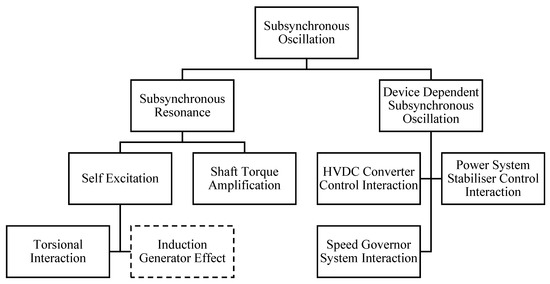
Figure 1.
Current classification of subsynchronous oscillations based on [8,13]. Solid boxes represent SSO phenomena that are electromechanical in nature. Dashed boxes represent electromagnetic phenomena.
“An electric power system condition where the electric network exchanges energy with a turbine generator at one or more of the natural frequencies of the combined system below the synchronous frequency of the system.”
SSR always requires a series capacitor [13] and is further categorized into self-excitation and shaft torque amplification. In contrast to SSR, the series capacitor plays no role in the DDSSO phenomenon. DDSSO is defined as the interaction between turbine-generator torsional systems and active power system components such as HVDC converter controls, power system stabilizers, and high-speed governor controls [8,13]. For DDSSO to occur, the torsional mass of a turbine-generator system is always required.
In the recent years, new types of electromagnetic subsynchronous oscillations have occurred, which cannot be categorized under the existing classification for two main reasons. First, as will be shown in Section 2.4, the existing definition of SSO excludes electromagnetic interaction phenomena, whereas the new SSO phenomena are all electromagnetic in nature. Second, in the existing SSO phenomena, conventional synchronous generators are always part of the adverse interactions. As will be shown in Section 2.2 and Section 2.3, two of the new SSO phenomena occur without the presence of conventional synchronous generators. The fundamental different nature of the new phenomena (i.e., electromagnetic interaction and absence of conventional synchronous generators) underlines the need for a new definition as well as reclassification of SSO. Therefore, first, a fundamental description of the new SSO types is given. For each type, real practical events are briefly discussed. Then, a new definition for SSO as well as a new classification is proposed.
2.1. DFIG-Series Capacitor Interaction
The DFIG-series capacitor interaction can be explained by considering the DFIG’s impedance model. The main components of a DFIG can be grouped into two categories: The DFIG’s grid side impedance consists of the filter’s impedance and the grid-side converter’s impedance, whereas the DFIG’s rotor-side impedance is formed by the induction machine’s impedance and the rotor-side converter’s impedance. During normal operation, the DC-link voltage is constant, following which and have a parallel connection [15,16], as is shown in Figure 2. The DC-link capacitor, connected between the RSC and GSC, decouples the RSC and GSC control and enables the independent operation of both converters.
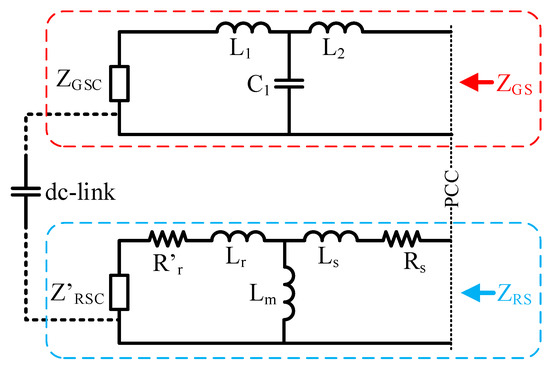
Figure 2.
Electrical connection of the grid side and rotor side of the DFIG under normal operation (based on [15]).
In the DFIG of Figure 2, an LCL filter is used to enhance the power quality at the point of common coupling (PCC). In this case, as seen from the PCC is defined as given in (1):
: Impedance of filter inductances and
: Impedance of filter capacitance
: Impedance of grid side converter
With slip as given in (2), as seen from the PCC is defined as given in (3):
: Electrical/stator speed
: Rotor speed
: Induction machine stator winding resistance
: Impedance of induction machine stator leakage reactance
: Impedance of induction machine rotor leakage reactance
: Impedance of induction machine magnetising reactance
: Induction machine rotor winding resistance
: referred to the stator side
: Impedance of rotor side converter
: referred to stator side
When the magnetizing reactance is neglected, (3) simplifies to:
As practical DFIGs generally have a large , the impedance of the DFIG, , is then approximately equal to [16,17,18]. From (4) it is observed that the damping of the DFIG is not constant and depends on . Under subsynchronous frequencies, can become negative and the damping of the DFIG system becomes negative. When the net damping, which is the sum of the DFIG damping and the damping provided by the transmission system, is negative, the power system will experience rapidly growing oscillations. For to be negative, subsynchronous currents, such that the frequency of these currents is lower than the rotor speed, are required. These currents are produced following a disturbance in among others a series capacitor compensated transmission line.
The interaction between a DFIG and a series capacitor was discussed for the first time in 2003 [19], which was well before the adverse interactions occurred for real in 2009 in the power system of Texas [20]. The study in [19] referred to an investigation of integrating between 500 MW and 1000 MW of wind generation into the Dakota transmission system. The generated electrical energy would be transported across large distances and one alternative to facilitate this was the use of series compensation. The influence of different degrees of series compensation was shown using damping torque analysis and a resonance at approx. 30 Hz was identified. Time domain simulations successfully validated the results. In [21], published in 2008, an SVC and a TCSC controller were designed for mitigating this type of interaction. Whereas both FACTS controllers were able to successfully mitigate the DFIG-series capacitor interaction, the performance of the TCSC was found to be superior. The performance of the FACTS controllers was validated using EMT simulations.
This phenomenon is a form of self-excitation and is similar to the induction generator effect (IGE) as was shown in [6]. Eigenvalue analysis performed in [6] on a DFIG connected to an infinite bus through a series-compensated transmission line, identified four SSO modes. The state space model developed for the DFIG consisted of 20 state variables, i.e., four generator states (stator and rotor fluxes), five drive train states (rotating speeds of three masses and two relative angles between the masses), four controller states for the RSC, one for the DC-link voltage, four controller states for the GSC, and two states for the converter transformer current. The state space model of the transmission network consisted the line currents and bus voltages. Using participation factor analysis, three modes (2.65, 3.23, and 6.74 Hz) were identified as torsional modes of the three mass drive train and the fourth mode (24.76 Hz) was identified as a network mode, which is mainly influenced by the series capacitor and the generator states (stator and rotor fluxes) of the DFIG. The participation factors of the RSC, the DC-link voltage and the GSC in the network mode were found to be practically zero.
As the converter controllers do not participate in this network mode, defining such an interaction as SSCI may be misleading. Thus, in the reclassification of SSO phenomena (Section 2.4), this phenomenon is defined as the DFIG-SSR.
The first DFIG-SSR in a real power system occurred on 22 October 2009 in the power system of Texas. The configuration of the South Texas power system is shown in Figure 3. Two wind farms are connected at the Zorillo substation, which is radially connected to the Ajo substation. The 345 kV transmission line from Nelson Sharpe to Rio Hondo consists of two line segments. The first segment connects substations Nelson Sharpe and Ajo, whereas the second segment connects substations Ajo and Rio Hondo. The second segment has a 90% compensation degree.
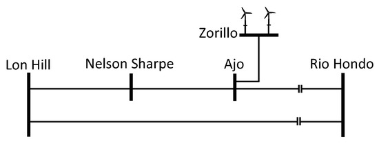
Figure 3.
Single line diagram of part of the South Texas transmission system.
On 22 October 2009, the Nelson Sharpe-Ajo line segment had a permanent fault and was isolated by the protection equipment. As a consequence, the new topology resulted in a radial connection of the wind farm (connected at Zorillo), through Ajo, to the series capacitor at Rio Hondo. In this new topology, the line segment Zorillo-Ajo-Rio Hondo has an equivalent degree of compensation of 75%. At these compensation degrees, the DFIG wind farm acted as a negative resistance to the subsynchronous currents. Following the fault, the subsynchronous currents increased rapidly to 3 per unit in 200 milliseconds. The series capacitor was bypassed after approx. three seconds, following which the oscillations subsided.
2.2. Converter-Grid Interaction
For the second SSO type, a D-PMSG is considered, where the generator is decoupled from the grid through the DC link. The GSC behaves like a capacitive reactance with negative damping and combined with weak grid conditions, i.e., a high equivalent line inductance L, this results in low resonance frequencies. If these resonances are excited, the oscillations will be amplified by the VSC.
The eigenvalue analysis for a D-PMSG was presented in [7], which reveals six SSO modes, of which one mode (32 Hz) becomes unstable with the weakened grid strength. Participation factor analysis showed that the states of the generator and MSC of the D-PMSG do not participate in this mode, whereas a large participation was observed for the states of the DC link (DC link voltage), the GSC (d-axis current tracking control) and the grid (d- and q-axis line currents). Further analysis of different grid strengths showed that weaker grids (i.e., higher line impedances) move the eigenvalues of the 32 Hz mode to the right half plane, implying instability [22].
In another study [23], the influence of the DC-link voltage control and the PLL on the stability of a weak power system was investigated. It was found that the control of the DC-link voltage can deteriorate the system stability as the power system becomes weaker. When the bandwidth of the PLL is close to that of the DC-link voltage control, the instability due to reducing grid strength is even more profound [24]. In such cases, the subsynchronous voltage oscillations with a frequency of approx. 10 Hz are observed
Contrary to the DFIG-SSR, this interaction is between the DC link, converter controllers and the grid, and is an actual example of SSCI. To distinguish the converter grid interaction (CGI) from other types of SSCI, it is defined here as SSCI-CGI.
A recent SSCI-CGI event happened in the UK on 9 August 2019 [2]. The interaction in this case was triggered by a disturbance in the transmission system, which ultimately reduced the Hornsea One wind farm’s active power output from 799 MW to 62 MW. Hornsea One is an offshore wind farm located 120 km from the coast of Yorkshire, UK, and consists of 174 wind turbines of 7 MW each. The wind farm is divided into three blocks of 400 MW each. Each block connects into its own offshore HVAC collector substation and all collector substations connect to a single HVAC reactive compensation station. From this station, the energy is transported to the onshore substation.
On 9 August 2019, the UK experienced significant storms, resulting in heavy rain and lightning. A lightning at 16:52:33:490 occurred and resulted in the tripping of a 400 kV transmission line. The line was reconnected after 20 s. In the meantime, the resulting unbalanced voltage dip due to the lightning caused the wind farm to inject reactive power in the grid, as expected by the grid code. In the following milliseconds, as the active power generated by the wind farm decreased in order to accommodate the increased reactive power injection, protection systems tripped many wind turbines, reducing the active power generation to 62 MW at 16:52:33:835. Combined with other parallel events, this reduction disrupted the power supply of approx. 1 million electricity consumers. According to the technical report of the wind farm owner [25], the active power reduction resulted from an undamped electrical resonance in the subsynchronous frequency range, which in turn was caused by the lightning strike. The voltage and active power responses of Hornsea One are shown in Figure 4 [2], where an oscillation of approx. 10 Hz is visible on the voltage.
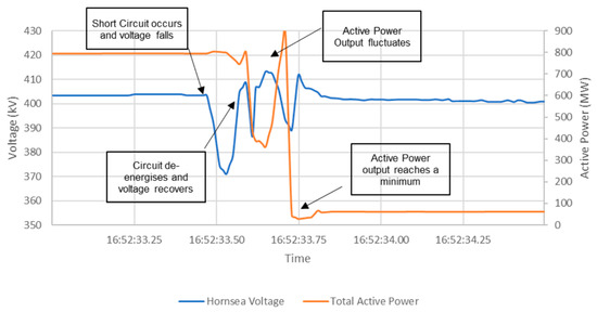
Figure 4.
Voltage and active power at Hornsea One [2].
Prior to the lightning and subsequent de-loading of Hornsea One, a poorly damped 10 Hz oscillation in the wind farm’s reactive power already existed, indicating a weak grid condition. The oscillation was triggered by a 2% voltage step change. It could therefore be reasonably argued that the transmission line outage following the lightning, weakened the grid even further and excited the SSO, leading to undamped voltage oscillations. More details on the event are reported in [2,25].
2.3. Converter-Converter Interaction
The converter-converter interaction (CCI) is another type of SSCI, where the interaction is between electrically close converters and is manifested as subsynchronous oscillations in the voltage/reactive power. From a conceptual perspective, the interaction can be caused when two converters try to control the voltage at the same substation, where both converters have different controller gains and time constants. Following a small disturbance such as a step change in the voltage, both converters will aim to control the voltage back to the setpoint. However, as both converters have different gains and time constants, their control speed will be different and this could potentially lead to subsynchronous voltage oscillations. This phenomenon is named in this work as SSCI-CCI.
A practical example of a SSCI-CCI event that happened in China on 16 September 2017 is given next. The single line diagram of the power system in the Xinjiang area is shown in Figure 5.
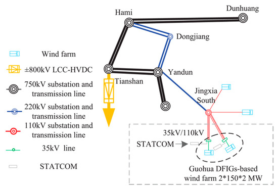
Figure 5.
Single line diagram of the wind power system in Xinjiang [5].
Wind energy is generated by 300 DFIGs of each 2 MW at 35 kV (high voltage side of generation transformer) and transported through 110 kV lines to the main power system. No series capacitors are installed in this part of the Xinjiang power system and reactive power requirements are met by six STATCOMs, installed on the 35 kV side of wind farms. The SSCI-CCI occurred between the STATCOM and the DFIG-based wind farm in the Guohua area, where the SSO event was characterised by three phases. Triggered by small disturbance, voltage oscillations with a frequency of 37.5 Hz were observed in the Guohua bus voltage in the first phase. In the second phase, harmonics caused by the voltage oscillations decreased the reactive power output of all the STATCOMs. In the third phase, the oscillations diverged and protection devices tripped the wind farms.
Detailed analysis of the event showed that the converter parameters of both, the STATCOM and the DFIG, influence the SSO. Eigenvalue analysis of the system revealed that large proportional and integral gains of the inner current control of the rotor side converter (RSC) increase the oscillation frequency and amplitude. Furthermore, large proportional and integral gains of the inner current control of the STATCOM mainly increase the oscillation amplitude. The SSCI-CCI in this case was mitigated by coordinated tuning of the controller parameters of the DFIG and STATCOM. More details on the event are reported in [5].
2.4. Proposed Reclassification of SSO
As was discussed in the previous sections, new types of SSO have emerged in the recent years. These phenomena (i.e., DFIG-SSR, SSCI-CGI and SSCI-CCI) are all electromagnetic in nature and as a result, the associated oscillations grow rapidly. When considering the existing definition of SSO, it can be concluded that:
- It excludes electromagnetic phenomena;
- It excludes interactions between power electronic converters and passive elements; and
- It excludes interactions among power electronic converters.
Taking the above into consideration, the definition of SSO needs to be modified in such a way, that (i) it does not exclude electromagnetic phenomena and (ii) it includes the interactions related to power electronic converters. The following definition is then proposed, in which the text in bold is added to the existing definition:
SSO is a subsynchronous interaction between (i) a turbine-generator and passive system elements such as series capacitors; (ii) a turbine-generator and active system elements such as power electronic equipment controls and static VAR system controls; or (iii) active system elements and either other active system elements such as wind farms or passive system elements such as a weak grid.
The next step is to include DFIG-SSR, SSCI-CGI, and SSCI-CCI in the classification of Figure 1. The proposed, new classification is done based on interacting components. The interaction of either a conventional synchronous generator or a DFIG with a series capacitor is categorized as SSR. As DFIG-SSR is form of self-excitation, it is categorized as such, together with torsional interaction and the induction generator effect. The interaction of a conventional synchronous generator with active system elements remain under the DDSSO category. No changes are made to the DDSSO classification. For the interaction of active system elements with either passive system elements or other active system elements a new category, ‘Subsynchronous Control Interactions’, is proposed. This category is on the same hierarchical level as SSR and DDSSO. The proposed reclassification of SSO phenomena is shown in Figure 6, where red boxes represent the new SSO categories, solid boxes represent electromechanical phenomena and dashed boxes represent electromagnetic phenomena.
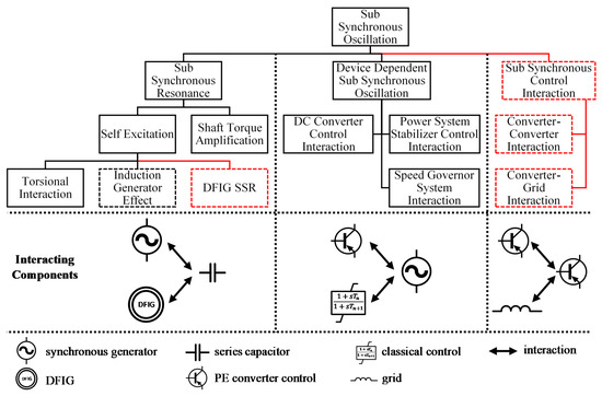
Figure 6.
Proposed additions to the existing SSO classification. Red boxes represent the new SSO categories, solid boxes represent electro-mechanical phenomena and dashed boxes represent electromagnetic phenomena.
An overview of recent DFIG-SSR ([20,26,27,28,29,30]), SSCI-CGI ([2,4,31])m and CCI [5] events is given in Figure 7.
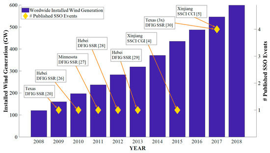
Figure 7.
Overview of worldwide installed wind generation and the number of published SSO event. It should be remembered that not all events are published and for those that are published, there is a time lag between the actual occurrence of the event and its publication through scientific channels.
The subsequent sections describe the available mitigation solutions available for each of these new categories of SSO phenomena.
3. Control Solutions
In this work, the DFIG-SSR and SSCI mitigation solutions are categorized as control solutions, hardware solutions and the system-level coordination. This section provides a review of the control solutions, including the tuning of converter controller parameters, new control concepts, digital filters, and supplementary damping controllers.
3.1. Tuning of Converter Controller Parameters
Converter controller parameters have an influence on DFIG-SSR and SSCI characteristics. Figure 8 and Figure 9 give an overview of general control diagrams of the GSC and MSC.
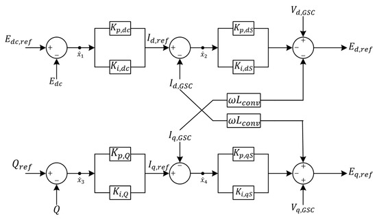
Figure 8.
Grid-side converter control of a WTG T3 + T4.
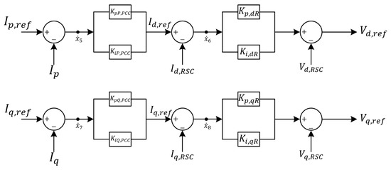
Figure 9.
Machine-side converter control of a WTG T3 + T4.
Practical controllers adopt a double-loop control (DLC) structure, and use the vector control with a stator aligned reference frame, containing the d-axis and q-axis control loop. The goal of the MSC is to regulate the active (d-axis) and reactive power (q-axis), whereas the GSC controls the DC-link (d-axis) and terminal voltages (q-axis). It is obvious that tuning controller parameters is straightforward for mitigating the DFIG-SSR and the SSCI. Tuning of MSC and GSC controller parameters was performed for real applications in [32] to mitigate DFIG-SSR, while tuning of the GSC parameters for mitigating SSCI-CGI is reported in [4]. The influence of controller parameters on the stability of the PEID is summarized in Table 1.

Table 1.
Influence of operating conditions and converter parameters on DFIG-SSR and SSCI.
In general, the controller tuning is the preferred solution to mitigate SSO, as it does not require using additional hardware devices or software update. Yet, this is not always practical. Controllers are designed to satisfy a wide range of operational and design requirements, such as fault ride-through (FRT) capability and power quality. Optimizing the PEID’s response to mitigate the DFIG-SSR or SSCI will come at the expense of, e.g., decreased power quality or a slower dynamic response of the converter. The existing parameter tuning practices do not always take the SSO into account. Hence, a multi-objective optimization is needed for tuning the controller parameters of PEID in modern power grids.
In addition to the DLC, the parameters of the used GSC-PLL may also have a detrimental impact on the SSCI and DFIG-SSR. In [43], an adaptive PLL is proposed for mitigating the SSCI-CGI, in which the GSC-PLL gains are adjusted in real-time as a function of the grid impedance. The grid impedance is calculated using the measured voltages and currents and the recursive least square algorithm. The major drawback of this approach is that the calculated grid impedance always lags behind the actual grid impedance due to the required calculation time. In the case of SSCI-CGI, the gain scheduling algorithm may not be able to timely and accurately calculate the grid impedance. It is envisaged that the gain scheduling approach for SSO mitigation will work adequately if the grid impedance could be forecasted.
In [44] the influence of the reference frame alignment on the DFIG-SSR was investigated. While changing the dq reference frame alignment from the stator to the grid voltage reduced the amplitude of the oscillations of DFIG-SSR, its implementation is impossible in practice, as it requires the measurement of a distant grid voltage at high sampling rate.
3.2. New Control Concepts
3.2.1. Virtual Synchronous Generator
The virtual synchronous generator (VSG) control concept is a type of grid-forming (GF) control. PEIDs with this concept exhibit dynamic characteristics similar to a conventional SG. In the VSG, a PLL is not used during normal operation, reducing the risk of SSCI-CGI. The VSG developed in [45,46] can mitigate SSOs resulting from SSCI-CGI. However, the VSG developed for the MSC of a DFIG in [47], resulted in poorer performance compared to the vector control (VC). Based on the eigenvalue analysis of both control concepts, it was found that VC maintains stability for higher levels of series compensation and lower wind speeds. This can be explained by the fact that rotor current transients are controlled by the MSC’s current control, whereas its control in the proposed VSG is achieved only through a current limiter [47]. The latter inherently has a poorer transient performance. A general drawback of the proposed VSG concept is that it merely mimics the conventional SG, yet does not take full advantage of the power controllability of PEID for the fast and flexible control of power system dynamics.
3.2.2. Direct Power Control
The Direct Power Control (DPC) is another type of GF control. In the DPC concept, the voltage magnitude and angle of the converter are controlled directly. By eliminating the current control in the DLC and replacing the rotor speed control in the MSC with a stator active power control based on the look-up table, the classical DLC can be transformed into DPC [48]. DPC reduces the DFIG’s equivalent resistance, which results in less negative damping in the subsynchronous frequency (SSF) range. Consequently, under identical operating conditions, the DPC has a superior performance in mitigating DFIG-SSR than the DLC [48]. The investigation was performed using a single-machine infinite-bus system and despite the promising results, further detailed investigation is needed to analyze the stability of the grid forming control in larger-scale power systems. With regards to SSCI-CGI, the analysis performed using the IEEE 118 bus system in [49] showed that DPC is able to mitigate SSCI-CGI.
3.2.3. Feedback Linearization Control
For mitigating the DFIG-SSR, the Feedback Linearization Control (FLC), which replaces the classical current control, is another option and it is designed for the MSC in [50] and for the GSC in [51]. The FLC enables the controlled system to be independent of operating conditions, which is advantageous for highly nonlinear systems. The FLC is essentially a model-based nonlinear control method, and hence, the control performance is directly influenced by the accuracy of the available system model. It can be enhanced by reducing the uncertainties associated with model inaccuracies. One way to achieve this is through a sliding mode control (SMC) [52]. However, a shortcoming of the SMC is the operating-condition-specific. Considering the same operating condition, the SMC has an improved performance compared to the FLC. To cope with uncertainties related to both the operating condition and model accuracy, the FLC and SMC are combined in [53,54]. The effectiveness of FLC and SMC in mitigating SSCI has not been reported.
A modification of the classical DLC for MSC is proposed in [55]. In this method, the MSC PI controllers are complemented with a motion-induced compensation scheme that adds an additional signal to the current control. This control scheme eliminates the negative resistance of the DFIG in the entire SSF range. The results showed that the DFIG-SSR can be mitigated in a wide range of operating conditions with good robustness against model and measurements errors. However, the fault behavior, power quality, and interoperability of this control for a realistic power system still need to be investigated.
3.3. Digital Filters
The digital filters block subsynchronous currents from flowing in to the rotor and consequently, negative resistances are not observed. To mitigate the DFIG-SSR, a second-order notch filter was implemented in [56]. In [57] a location-dependent performance index is proposed to identify the best location in the control system for placing the digital filter. Using this index, the MSC’s d-axis inner current loop and the GSC’s d-axis outer voltage loop were identified as the most suitable locations. A major drawback of the notch filter is that it is tuned for a fixed frequency, whereas the frequency where the DFIG-SSR occurs is variable and dependent on the operating conditions. This limitation could explain why the use of notch filters for this purpose is limited in practice.
To cope with this limitation, a scheme based on a virtual resistor (VR) that increases the MSC damping for a predefined SSF range is introduced in [16]. The performance of this scheme was compared with the controller parameter tuning and the method of adding VR in the GSC. The result showed that the VR in the MSC yields the best performance, as the damping is influenced directly in this way. The damping can also be influenced indirectly by adding an integral gain in the current control of the MSC [58], which has the same effect of adding a series virtual inductance (DFIGs have a smaller negative resistance at lower ).
3.4. Supplementary Damping Control
A supplementary damping controller (SDC) is an auxiliary controller in the PEID MSC or in FACTS devices on the grid side (presented in Section 4), designed to dampen out oscillations. The control structure of a generic SDC is given in Figure 10. It consists of a gain, a washout filter and lead-lag compensation blocks.
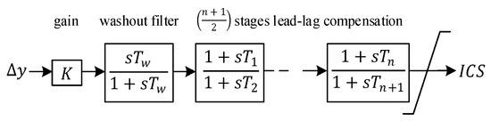
Figure 10.
Control structure of a generic supplementary controller.
For the input of the SDC, the active power output [59], the rotor speed deviation [60], the line current [59] and the voltage across the series capacitor are used. In [61] an SDC is developed for the GSC, and is independent of the input signal. The input control signal (ICS) of the SDC can be supplied as feedback signal to either the GSC [30,61,62] or the MSC [60,63]. The SDC developed in [64] provides the feedback signal to the GSC as well as the MSC. The GSC is perceived as a more suitable location for the SDC because of the similarities between the GSC and a STATCOM, of which the latter has excellent damping capabilities [65].
The efficiency of the SDC depends, to a large extend, on the proper design of SDC parameters. The residue-based method using the and matrices of the linearized system equations [66] and the parameter optimization based on the time-domain simulations are among the most used methods for this purpose. The residue based analysis in [67] showed that a simple SDC with a proportional controller utilizing or as the input, destabilizes any present supersynchronous mode. When using both sub- and super-synchronous oscillation modes can be stabilized. While most of research works focused on mitigating DFIG-SSR in a single wind farm, SDCs are installed on multiple wind farms in [68] to mitigate different DFIG-SSR modes.
One major limitation of the residue-based and time-domain based optimization is the inability to efficiently consider a wide range of operating conditions in the parameter tuning process. To tackle this, three solutions are reported in literature. First, an improved particle swarm optimization method for SDC parameter tuning under different levels of series compensation is proposed in [63]. Second, a probabilistic based SDC design is proposed in [69]. Lastly, to obtain the optimized performance across multiple operating conditions, concepts for real-time adaptive damping controllers using the wind speed [70], the level of series compensation [71] and the number of in-service wind turbines [3] were developed.
While these tuning methods can identify the SDC parameters that mitigate DFIG-SSR under different wind speeds and series compensation levels, they fail to incorporate the different grid topologies in their optimization problem. The DFIG-SSR is more prone to happen with a fixed series capacitor, where the level of compensation does not change once it is in operation. It is more practical and useful to include different grid damping levels, instead of compensation levels, in the formulation of the optimization problem, as different grid topologies and load levels (i.e., grid damping) are more realistic than the different compensation levels. The main challenge for adaptive damping controllers then becomes how to adequately determine the grid damping, the wind speed, and the number of wind turbines in operation.
4. Hardware Solutions
Hardware solutions encompass those solutions that require hardware to be installed in the system operator’s grid. These are divided into FACTS and other VSC based methods.
4.1. FACTS
FACTS devices, except for a thyristor controller series capacitor (TCSC), installed to mitigate DFIG-SSR have to be equipped with the SDC for damping. For this purpose, a Static Var Generator (SVC) with the SDC was used in [72]. The primary goal of the SVC was to provide the voltage support. The input of the auxiliary SDC was the line power, calculated from the measured current and voltage at the SVC connection point. Compared to the FSC, the TCSC inherently prevents the DFIG-SSR and it was used in [73]. When comparing the performance of the TCSC (series device) with the SVC (shunt device), it is observed that the series device is superior in mitigating DFIG-SSR. This is confirmed by [74], where a universal power flow controller (UPFC) was equipped with a series as well as shunt SDC. It was found that the series SDC was able to dampen out oscillations much faster than the shunt SDC. For stabilizing the DFIG-SSR using SDCs, the local signals were mainly used as inputs.
An SDC-equipped STATCOM was designed in [75] for mitigating the DFIG-SSR. The input for the SDC is The STATCOM controller produces a modulation index and phase angle difference signal and it was found that the best stabilizing performance is achieved when the ICS is added to the modulation index. Yet, there are still some challenges for this solution. One deals with how to identify which DFIG’s to use with the SDC in a multimachine wind farm. Another one deals with the latency between the DFIG and STATCOM. A major drawback of any FACTS based solution is that it requires capital intensive investments. If on top of the DFIG-SSR mitigation, additional system services such as voltage support are required, the SVC and STATCOM are good solutions. In all other cases, more cost-effective solutions exist. When a risk for DFIG-SSR is identified in the design stage, the FSC can be replaced by a TCSC. Replacing an FSC before the end of its lifetime is not a cost-effective measure.
For SSCI-CGI, the grid strength is inversely proportional to the probability of the adverse interactions. Therefore, FACTS devices that increase the system strength also contribute to mitigate SSCI, albeit that publications covering this are rare. Caution should be taken as the FACTS devices installed for mitigating SSCI-CGI could potentially result in the SSCI-CCI.
4.2. Other VSC-Based Solutions
FACTS devices mitigate DFIG-SSR through an SDC, which in real power systems would only be a secondary goal of such a device. Commissioning FACTS only for DFIG-SSR or SSCI mitigation is not a cost-effective solution. Therefore, other independent VSC-based methods were developed. A robust subsynchronous damping controller was reported in [76], which can be seen as a controlled current source, governed by a damping calculator and a VSC based subharmonic voltage generator. The calculator extracts the subsynchronous modes from the bus voltage and line current. Control signals based on the extracted subsynchronous modes are used as input to the voltage generator, which then injects subharmonic currents into the system to stabilize DFIG-SSR. Eigenvalue analysis and time domain simulations showed the stable behavior of this solution across a wide range of operating conditions. Unlike a majority of the literature, the FRT of the DFIG wind farm with and without the mitigation solution is given as well, showing that the solution does not jeopardize the FRT performance. It will be implemented in the Guyuan power system.
An innovative solution for mitigating SSR using a battery energy storage system (BESS) is designed in [77], where a SDC is added to the VSC of the BESS. Although this solution was designed to mitigate classical SSR, the concept could also be used for mitigating DFIG-SSR. The BESS could then also be used for frequency support, where algorithms would be needed that gives priority to either DFIG-SSR mitigation or frequency support, in case both events happen simultaneously.
5. System-Level Coordination
With the increasing number of electrically close PEID, SSO solutions based on tuning of individual controller parameters will eventually get exhausted. In such cases, the system level coordination can help to mitigate SSO in a rather unconventional way. In system level coordination, control actions are taken based on system measurements. Examples of such solutions are gain scheduling and protection.
In [78], a synchrophasor based gain scheduling of a SDC in a TCSC was designed. The gains were dynamically adjusted based on measurements of individual wind turbines in the wind farm and it was concluded that the proposed concept performs better than local TCSC control. However, such a solution requires using the wide-area measurement system, where the reliability, accuracy, and speed of the communication link have a critical impact on the TCSC’s damping response.
The last resort against the unstable SSCI and DFIG-SSR is the protection. A protection algorithm for tripping a wind farm subjected to the DFIG-SSR was developed in [79]. The concept is based on three processes. In the first process, frequency scans are performed across multiple credible operating conditions to determine the decision-making thresholds such as the minimum damping. The continuous monitoring of system variables is performed in the second process. In the last process the monitored variables are continuously compared with the predefined thresholds. When the limit violations are detected, a trip command is issued to the wind farm. Using this method, the oscillations were detected within 25 ms and the trip signal was issued in the following 50 ms. The detection algorithm in [80] achieved a detection time of maximum 29 ms for DFIG-SSR.
An SSF relay is another type of protection that can be used for disconnecting either the wind farm (in case of DFIG-SSR and SSCI) or the series capacitor (in case of DFIG-SSR). The SSF relay developed in [27] is capable of detecting multiple oscillations between 5 and 25 Hz and issuing either alarms or trip commands. The timescale of detection and trip command was not given for this SSF relay.
From the system operation perspective, protection solutions are the most intrusive, as they abruptly disconnect generation and transform a small signal stability problem to a (more difficult to manage) large disturbance.
6. Open Issues and Challenges
Mitigation solutions reviewed in this work and summarized in Table 2 are mostly developed using a single machine representation. While under strict preconditions, this is acceptable for assessing the dynamic stability of a power system [81], this approach cannot be used for designing SSO mitigation solutions, as those preconditions are not respected. Therefore, a thorough analysis on the validity of those mitigation solutions developed using a single machine modeling is required. Potential computational bottlenecks can be solved using high performance computers.
Table 2.
Overview of mitigation solutions.
Another open issue is the development of robust methods and assessment criteria to coordinate different controllers of electrically close PEID. PEIDs are more and more required to deliver ancillary services and one way to achieve this is by installing FACTS devices close to the PEID. Coordination among the controls of the PEID and the FACTS is then of utmost importance as it can mitigate DFIG-SSR [82] and SSCI [35].
7. Conclusions
This paper first reviewed new SSO types related to PEIDs. Existing eigenvalue analyses of emerging SSO showed that the DFIG-series capacitor interaction is in fact not a controller interaction. Based on participating state variables, it was proposed to define this interaction as DFIG-SSR. Then, a framework for the classification of SSO phenomena was designed, where phenomena are categorized based on the participating state variables. As such, the existing classification was extended with three new SSO phenomena: DFIG-SSR, SSCI-CCI, and SSCI-GCI.
Then, for each phenomena, available mitigation solutions, categorized into control solutions, hardware solutions and the system level coordination, were reviewed. It was found that a majority of these solutions are developed to mitigate the DFIG-SSR, the oldest of the three phenomena. For the SSCI-CCI, the newest of the three, plenty of research is still needed to better grasp the phenomenon and design adequate mitigation measures.
The observed trend is that control and hardware solutions reach a saturation, and that the focus shifts towards development of system solutions, albeit that control solutions remain preferred whenever possible. Main challenges for control solutions include the modification of the tuning algorithm to account for multiple operating and design criteria and the validation of such solutions using a fully-detailed wind farm model. Hardware solutions are robust and can additionally provide ancillary services. A major drawback is the high costs. System solutions are just recently being developed and have not yet reached a level of maturity for them to be used in actual real power systems.
Author Contributions
Conceptualization, V.S., X.W. and J.R.T.; methodology, V.S., X.W., J.R.T. and M.v.d.M.; formal analysis, V.S., X.W. and J.R.T.; investigation, V.S. and X.W.; data curation, V.S.; writing—original draft preparation, V.S. and X.W.; writing—review and editing, V.S., X.W., J.R.T. and M.v.d.M.; visualization, V.S. and X.W.; supervision, J.R.T., X.W. and M.v.d.M.; project administration, V.S. and J.R.T.; funding acquisition, J.R.T. and M.v.d.M. All authors have read and agreed to the published version of the manuscript.
Funding
This research has received funding from the European Union’s Horizon 2020 research and innovation programme under grant agreement No 691800. This paper reflects only the authors’ views and the European Commission is not responsible for any use that may be made of the information it contains.
Conflicts of Interest
The authors declare no conflict of interest.
References
- Wang, X.; Blaabjerg, F. Harmonic Stability in Power Electronic-Based Power Systems: Concept, Modeling, and Analysis. IEEE Trans. Smart Grid 2019, 10, 2858–2870. [Google Scholar] [CrossRef]
- Technical Report on the Events of 9 August 2019; National Grid ESO: Warwick, UK, 2019.
- Ghafouri, M.; Karaagac, U.; Mahseredjian, J.; Karimi, H. SSCI Damping Controller Design for Series Compensated DFIG based Wind Parks Considering Implementation Challenges. IEEE Trans. Power Syst. 2019, 34, 2644–2653. [Google Scholar] [CrossRef]
- Xu, Y.; Cao, Y. Sub-synchronous oscillation in PMSGs based wind farms caused by amplification effect of GSC controller and PLL to harmonics. IET Renew. Power Gener. 2018, 12, 844–850. [Google Scholar] [CrossRef]
- Xu, Y.; Zhao, S.; Cao, Y.; Sun, K. Understanding Subsynchronous Oscillations in DFIG-based Wind Farms without Series Compensation. IEEE Access 2019, 7, 107201–107210. [Google Scholar] [CrossRef]
- Suriyaarachchi, D.H.R.; Annakkage, U.D.; Karawita, C.; Jacobson, D.A. A procedure to study sub-synchronous interactions in wind integrated power systems. IEEE Trans. Power Syst. 2013, 28, 377–384. [Google Scholar] [CrossRef]
- Huang, B.; Sun, H.; Liu, Y.; Wang, L.; Chen, Y. Study on subsynchronous oscillation in D-PMSGs-based wind farm integrated to power system. IET Renew. Power Gener. 2018, 13, 16–26. [Google Scholar] [CrossRef]
- IEEE Subsynchronous Resonance Working Group. Reader’s Guide to Subsynchronous Resonance. IEEE Trans. Power Syst. 1992, 7, 150–157. [Google Scholar] [CrossRef]
- Gu, K.; Wu, F.; Zhang, X.-P. Sub-synchronous interactions in power systems with wind turbines: A review. IET Renew. Power Gener. 2018, 13, 4–15. [Google Scholar] [CrossRef]
- Shair, J.; Xie, X.; Wang, L.; Liu, W.; He, J.; Liu, H. Overview of emerging subsynchronous oscillations in practical wind power systems. Renew. Sustain. Energy Rev. 2019, 99, 159–168. [Google Scholar] [CrossRef]
- Ghasemi, H.; Gharehpetian, G.B.; Nabavi-Niaki, S.A.; Aghaei, J. Overview of subsynchronous resonance analysis and control in wind turbines. Renew. Sustain. Energy Rev. 2013, 27, 234–243. [Google Scholar] [CrossRef]
- Virulkar, V.B.; Gotmare, G.V. Sub-synchronous resonance in series compensated wind farm: A review. Renew. Sustain. Energy Rev. 2016, 55, 1010–1029. [Google Scholar] [CrossRef]
- IEEE Subsynchronous Resonance Working Group. Terms, Definitions and Symbols for Subsynchronous Oscillations. IEEE Trans. Power Appar. Syst. 1985, 104, 1326–1334. [Google Scholar]
- Anderson, P.M.; Agrawal, B.L.; Van Ness, J.E. Subsynchronous Resonance in Power Systems; IEEE Publication: New York, NY, USA, 1990. [Google Scholar]
- Song, Y.; Wang, X.; Blaabjerg, F. Impedance-Based High-Frequency Resonance Analysis of DFIG System in Weak Grids. IEEE Trans. Power Electron. 2017, 32, 3536–3548. [Google Scholar] [CrossRef]
- Vieto, I.; Sun, J. Damping of subsynchronous resonance involving Type-III wind turbines. In Proceedings of the 2015 IEEE 16th Workshop on Control and Modeling for Power Electronics (COMPEL), Vancouver, BC, Canada, 12–15 July2015. [Google Scholar] [CrossRef]
- Fan, L.; Miao, Z. Nyquist-stability-criterion-based SSR explanation for type-3 wind generators. IEEE Trans. Energy Convers. 2012, 27, 807–809. [Google Scholar] [CrossRef]
- Vieto, I.; Sun, J. Impedance modeling of doubly-fed induction generators. In Proceedings of the 2015 17th European Conference on Power Electronics and Applications, EPE-ECCE Europe 2015, Geneva, Switzerland, 8–10 September 2015. [Google Scholar]
- Pourbeik, P.; Koessler, R.J.; Dickmander, D.L.; Wong, W. Integration of Large Wind Farms into Utility Grids (Part 2-Performance Issues). In Proceedings of the 2003 IEEE Power Engineering Society General Meeting, Toronto, ON, Canada, 13–17 July 2003; Volume 3, pp. 520–1525. [Google Scholar]
- Adams, J.; Carter, C.; Huang, S.H. ERCOT experience with Sub-synchronous Control Interaction and proposed remediation. In Proceedings of the IEEE Power Engineering Society Transmission and Distribution Conference, Orlando, FL, USA, 7–10 May 2012; pp. 1–5. [Google Scholar]
- Varma, R.K.; Auddy, S.; Semsedini, Y. Mitigation of subsynchronous resonance in a series-compensated wind farm using FACTS controllers. IEEE Trans. Power Deliv. 2008, 23, 1645–1654. [Google Scholar] [CrossRef]
- Li, Y.; Fan, L.; Miao, Z. Stability Control for Wind in Weak Grids. IEEE Trans. Sustain. Energy 2019, 10, 2094–2103. [Google Scholar] [CrossRef]
- Huang, Y.; Yuan, X.; Hu, J.; Zhou, P. Modeling of VSC Connected to Weak Grid for Stability Analysis of DC-Link Voltage Control. IEEE J. Emerg. Sel. Top. Power Electron. 2015, 3, 1193–1204. [Google Scholar] [CrossRef]
- Fan, L. Modeling Type-4 Wind in Weak Grids. IEEE Trans. Sustain. Energy 2019, 10, 853–864. [Google Scholar] [CrossRef]
- Appendices to the Technical Report on the Events of 9 August 2019; National Grid ESO: Warwick, UK, 2019.
- Yunhong, L.; Hui, L.; Xiaowei, C.; Jing, H.; Li, Y. Impact of PMSG on SSR of DFIGs connected to series-compensated lines based on the impedance characteristics. J. Eng. 2017, 2017, 2184–2187. [Google Scholar] [CrossRef]
- Narendra, K.; Fedirchuk, D.; Midence, R.; Zhang, N.; Mulawarman, A.; Mysore, P.; Sood, V. New microprocessor based relay to monitor and protect power systems against sub-harmonics. In Proceedings of the 2011 IEEE Electrical Power and Energy Conference, Winnipeg, MB, Canada, 3–5 October 2011; pp. 438–443. [Google Scholar]
- Wang, L.; Xie, X.; Jiang, Q.; Liu, H.; Li, Y.; Liu, H. Investigation of SSR in Practical DFIG-Based Wind Farms Connected to a Series-Compensated Power System. IEEE Trans. Power Syst. 2015, 30, 2772–2779. [Google Scholar] [CrossRef]
- Xie, X.; Zhang, X.; Liu, H.; Liu, H.; Li, Y.; Zhang, C. Characteristic Analysis of Subsynchronous Resonance in Practical Wind Farms Connected to Series-Compensated Transmissions. IEEE Trans. Energy Convers. 2017, 32, 1117–1126. [Google Scholar] [CrossRef]
- Li, Y.; Fan, L.; Miao, Z. Replicating Real-World Wind Farm SSR Events. IEEE Trans. Power Deliv. 2019. [Google Scholar] [CrossRef]
- Huang, S.H.; Schmall, J.; Conto, J.; Adams, J.; Zhang, Y.; Carter, C. Voltage control challenges on weak grids with high penetration of wind generation: ERCOT experience. In Proceedings of the 2012 IEEE Power and Energy Society General Meeting, San Diego, CA, USA, 22–26 July 2012. [Google Scholar]
- Chen, A.; Xie, D.; Zhang, D.; Gu, C.; Wang, K. PI parameter tuning of converters for sub-synchronous interactions existing in grid-connected DFIG wind turbines. IEEE Trans. Power Electron. 2019, 34, 6345–6355. [Google Scholar] [CrossRef]
- Ma, J.; Jiang, L.; Wu, M.; Zhang, C.; Liu, F. SSR analysis of DFIG based wind farm considering spatial distribution of wind speed. In Proceedings of the IEEE Power and Energy Society General Meeting, Boston, MA, USA, 17–21 July 2016. [Google Scholar]
- Jin, W.; Lu, Y. Stability Analysis and Oscillation Mechanism of the DFIG-Based Wind Power System. IEEE Access 2019, 7, 88937–88948. [Google Scholar] [CrossRef]
- Chen, Y.; Liu, Y.; Sun, H.; Huang, B.; Wang, L. SSCI Problem of D-PMSGs Based Wind Farm Considering Frequency Characteristics of Grid Impedance. In Proceedings of the 2018 International Conference on Power System Technology (POWERCON), Guangzhou, China, 6–8 November 2018. [Google Scholar]
- Liu, H.; Xie, X.; He, J.; Xu, T.; Yu, Z.; Wang, C.; Zhang, C. Subsynchronous Interaction between Direct-Drive PMSG Based Wind Farms and Weak AC Networks. IEEE Trans. Power Syst. 2017, 32, 4708–4720. [Google Scholar] [CrossRef]
- Zhou, J.Z.; Ding, H.; Fan, S.; Zhang, Y.; Gole, A.M. Impact of short-circuit ratio and phase-locked-loop parameters on the small-signal behavior of a VSC-HVDC converter. IEEE Trans. Power Deliv. 2014, 29, 2287–2296. [Google Scholar] [CrossRef]
- Papangelis, L.; Debry, M.S.; Prevost, T.; Panciatici, P.; Van Cutsem, T. Stability of a voltage source converter subject to decrease of short-circuit capacity: A case study. In Proceedings of the 2018 Power Systems Computation Conference (PSCC), Dublin, Ireland, 11–15 June 2018. [Google Scholar]
- Li, Y.; Fan, L.; Miao, Z. Wind in Weak Grids: Low-Frequency Oscillations, Subsynchronous Oscillations, and Torsional Interactions. IEEE Trans. Power Syst. 2019. [Google Scholar] [CrossRef]
- Xie, X.; Wang, L.; Liu, X.; Jiang, Q. Centralised solution for subsynchronous control interaction of doubly fed induction generators using voltage-sourced converter. IET Gener. Transm. Distrib. 2015, 9, 2751–2759. [Google Scholar]
- Fan, L.; Zhu, C.; Miao, Z.; Hu, M. Modal analysis of a DFIG-based wind farm interfaced with a series compensated network. IEEE Trans. Energy Convers. 2011, 26, 1010–1020. [Google Scholar] [CrossRef]
- Wang, Y.; Wu, Q.; Yang, R.; Tao, G.; Liu, Z. H ∞ current damping control of DFIG based wind farm for sub-synchronous control interaction mitigation. Electr. Power Energy Syst. 2018, 98, 509–519. [Google Scholar] [CrossRef]
- Huang, L.; Xin, H.; Wang, Z.; Huang, W.; Wang, K. An Adaptive Phase-Locked Loop to Improve Stability of Voltage Source Converters in Weak Grids. In Proceedings of the 2018 IEEE Power & Energy Society General Meeting (PESGM), Portland, OR, USA, 5–10 August 2018. [Google Scholar]
- Baesmat, H.J.; Bodson, M. Suppression of Sub-Synchronous Resonances through Excitation Control of Doubly-Fed Induction Generators. IEEE Trans. Power Syst. 2019, 34, 4329–4340. [Google Scholar] [CrossRef]
- Roldán-Pérez, J.; Suul, J.A.; D’Arco, S.; Rodríguez-Cabero, A.; Prodanovic, M. Virtual synchronous machine control of VSC HVDC for power system oscillation damping. In Proceedings of the IECON 2018-44th Annual Conference of the IEEE Industrial Electronics Society, Washington, DC, USA, 21–23 October 2018; pp. 6026–6031. [Google Scholar]
- Cao, Y.; Wang, W.; Li, Y.; Tan, Y.; Chen, C.; He, L.; Häger, U.; Rehtanz, C. A Virtual Synchronous Generator Control Strategy for VSC-MTDC Systems. IEEE Trans. Energy Convers. 2018, 33, 750–761. [Google Scholar] [CrossRef]
- Gu, K.; Wu, F.; Zhang, X.-P.; Ju, P.; Zhou, H.; Luo, J.; Li, J. SSR Analysis of DFIG-Based Wind Farm With VSM Control Strategy. IEEE Access 2019, 7, 118702–118711. [Google Scholar] [CrossRef]
- Wang, L.; Peng, J.; You, Y.; Ma, H. SSCI performance of DFIG with direct controller. IET Gener. Transm. Distrib 2017, 11, 2697–2702. [Google Scholar] [CrossRef]
- Ndreko, M.; Ruberg, S.; Winter, W. Grid Forming Control for Stable Power Systems with up to 100% Inverter Based Generation: A Paradigm Scenario using the IEEE 118-bus System. In Proceedings of the 17th International Wind Integration Workshop, Stockholm, Sweden, 16–18 October 2018; pp. 17–19. [Google Scholar]
- Chowdhury, M.A.; Shafiullah, G.M. SSR Mitigation of Series-Compensated DFIG Wind Farms by a Nonlinear Damping Controller Using Partial Feedback Linearization. IEEE Trans. Power Syst. 2018, 33, 2528–2538. [Google Scholar] [CrossRef]
- Chowdhury, M.A.; Mahmud, M.A.; Shen, W.; Pota, H.R. Nonlinear Controller Design for Series-Compensated DFIG-Based Wind Farms to Mitigate Subsynchronous Control Interaction. IEEE Trans. Energy Convers. 2017, 32, 707–719. [Google Scholar] [CrossRef]
- Karunanayake, C.; Ravishankar, J.; Dong, Z.Y. Nonlinear SSR Damping Controller for DFIG based Wind Generators Interfaced to Series Compensated Transmission Systems. IEEE Trans. Power Syst. 2020, 35, 1156–1165. [Google Scholar] [CrossRef]
- Li, P.; Wang, J.; Xiong, L.; Ma, M. Robust Nonlinear Controller Design for Damping of Sub-Synchronous Control Interaction in DFIG-Based Wind Farms. IEEE Access 2019, 7, 16626–16637. [Google Scholar] [CrossRef]
- Li, P.; Xiong, L.; Wu, F.; Ma, M.; Wang, J. Sliding mode controller based on feedback linearization for damping of sub- synchronous control interaction in DFIG-based wind power plants. Electr. Power Energy Syst. 2019, 107, 239–250. [Google Scholar] [CrossRef]
- Gu, Y.; Liu, J.; Green, T.; Li, W.; He, X. Motion-Induction Compensation to Mitigate Sub-Synchronous Oscillation in Wind Farms. IEEE Trans. Sustain. Energy 2019, 11, 1247–1256. [Google Scholar] [CrossRef]
- He, H.; Lv, D.; Wen, L.; Lu, W.; Geng, H.; Gao, J. Analysis and Suppression Strategies of Sub-synchronous Resonance on DFIG. In Proceedings of the 2018 IEEE International Power Electronics and Application Conference and Exposition, Shenzhen, China, 4–7 November 2018; pp. 1–5. [Google Scholar]
- Liu, H.; Xie, X.; Li, Y.; Liu, H.; Hu, Y. Mitigation of SSR by embedding subsynchronous notch filters into DFIG converter controllers. IET Gener. Transm. Distrib. 2017, 11. [Google Scholar] [CrossRef]
- Meng, Y.; Pan, X.; Ma, H.; Li, K.; Yu, J.; Wang, X. Analysis and mitigation of subsynchronous resonance based on integral control for DFIG-based wind farm. IET Gener. Transm. Distrib. 2019, 13, 1718–1725. [Google Scholar] [CrossRef]
- Karaagac, U.; Faried, S.O.; Mahseredjian, J.; Edris, A.A. Coordinated Control of Wind Energy Conversion Systems for Mitigating Subsynchronous Interaction in DFIG-Based Wind Farms. IEEE Trans. Smart Grid 2014, 5, 2440–2449. [Google Scholar] [CrossRef]
- Zhao, B.; Li, H.; Wang, M.; Chen, Y.; Liu, S.; Yang, D.; Yang, C.; Hu, Y.; Chen, Z.; Senior Member, IEEE. An active power control strategy for a DFIG-based wind farm to depress the subsynchronous resonance of a power system. Int. J. Electr. Power Energy Syst. 2015, 69, 327–334. [Google Scholar]
- Mohammadpour, H.A.; Ghaderi, A.; Mohammadpour, H.; Santi, E. SSR damping in wind farms using observed-state feedback control of DFIG converters. Electr. Power Syst. Res. 2015, 123, 57–66. [Google Scholar] [CrossRef]
- Mohammadpour, H.A.; Santi, E.; Ghaderi, A. Analysis of sub-synchronous resonance in doubly-fed induction generator-based wind farms interfaced with gate–controlled series capacitor. IET Gener. Transm. Distrib. 2014, 8, 1998–2011. [Google Scholar] [CrossRef]
- Yao, J.; Wang, X.; Li, J.; Liu, R.; Zhang, H. Sub-Synchronous Resonance Damping Control for Series-Compensated DFIG-Based Wind Farm With Improved Particle Swarm Optimization Algorithm. IEEE Trans. Energy Convers. 2019, 34. [Google Scholar] [CrossRef]
- Leon, A.E.; Solsona, J.A. Sub-synchronous interaction damping control for DFIG wind turbines. IEEE Trans. Power Syst. 2015, 30, 419–428. [Google Scholar] [CrossRef]
- El-Moursi, M.S.; Bak-Jensen, B.; Abdel-Rahman, M.H. Novel STATCOM controller for mitigating SSR and damping power system oscillations in a series compensated wind park. IEEE Trans. Power Electron. 2010, 25, 429–441. [Google Scholar] [CrossRef]
- Dattaray, P.; Chakravorty, D.; Wall, P.; Yu, J.; Terzija, V. A Novel Control Strategy for Subsynchronous Resonance Mitigation Using 11 kV VFD-Based Auxiliary Power Plant Loads. IEEE Trans. Power Deliv. 2018, 33, 728–740. [Google Scholar] [CrossRef]
- Fan, L.; Miao, Z. Mitigating SSR using DFIG-based wind generation. IEEE Trans. Sustain. Energy 2012, 3, 349–358. [Google Scholar] [CrossRef]
- Leon, A.E. Integration of DFIG-Based Wind Farms into Series-Compensated Transmission Systems. IEEE Trans. Sustain. Energy 2016, 7, 451–460. [Google Scholar] [CrossRef]
- Bian, X.; Ding, Y.; Jia, Q.; Shi, L.; Zhang, X.-P.; Lo, K.L. Mitigation of sub-synchronous control interaction of a power system with DFIG-based wind farm under multi-operating points. IET Gener. Transm. Distrib. 2018, 12, 5834–5842. [Google Scholar] [CrossRef]
- Ghaffarzadeh, H.; Mehrizi-sani, A. Mitigation of Subsynchronous Resonance Induced by a Type III Wind System. IEEE Trans. Sustain. Energy 2019, 11, 1717–1727. [Google Scholar] [CrossRef]
- Xu, Y.; Zhao, S. Mitigation of subsynchronous resonance in series-compensated dfig wind farm using active disturbance rejection control. IEEE Access 2019, 7, 68812–68822. [Google Scholar] [CrossRef]
- Xie, H.; De Oliveira, M.M. Mitigation of SSR in presence of wind power and series compensation by SVC. In Proceedings of the 2014 International Conference on Power System Technology, Powercon, Chengdu, China, 20–22 October 2014; pp. 2819–2826. [Google Scholar]
- Piyasinghe, L.; Miao, Z.; Khazaei, J.; Fan, L. Impedance model-based SSR analysis for TCSC compensated type-3 wind energy delivery systems. IEEE Trans. Sustain. Energy 2015, 6, 179–187. [Google Scholar] [CrossRef]
- Golshannavaz, S.; Aminifar, F.; Nazarpour, D. Application of UPFC to enhancing oscillatory response of series-compensated wind farm integrations. IEEE Trans. Smart Grid 2014, 5, 1961–1968. [Google Scholar] [CrossRef]
- Moharana, A.; Varma, R.K.; Seethapathy, R. SSR alleviation by STATCOM in induction-generator-based wind farm connected to series compensated line. IEEE Trans. Sustain. Energy 2014, 5, 947–957. [Google Scholar] [CrossRef]
- Zhang, X.; Xie, X.; Shair, J.; Liu, H.; Li, Y.; Li, Y. A Grid-side Subsynchronous Damping Controller to Mitigate Unstable SSCI and its Hardware-in-the-loop Tests. IEEE Trans. Sustain. Energy 2020, 11, 1548–1558. [Google Scholar] [CrossRef]
- Khazaei, J.; Asrari, A.; Idowu, P.; Shushekar, S. Sub-Synchronous Resonance Damping using Battery Energy Storage System. 2018 N. Am. Power Symp. 2019, 2018, 1–6. [Google Scholar]
- Mahish, P.; Pradhan, A.K. Mitigating Subsynchronous Resonance Using Synchrophasor Data Based Control of Wind Farms. IEEE Trans. Power Deliv. 2020, 35, 364–376. [Google Scholar] [CrossRef]
- Salehi, F.; Matsuo, I.B.M.; Brahman, A.; Tabrizi, M.A.; Lee, W.-J. Sub-Synchronous Control Interaction Detection: A Real-Time Application. IEEE Trans. Power Deliv. 2019, 35. [Google Scholar] [CrossRef]
- Li, H.; Abdeen, M.; Chai, Z.; Kamel, S.; Xie, X.; Hu, Y.; Wang, K. An Improved Fast Detection Method on Subsynchronous Resonance in a Wind Power System with a Series Compensated Transmission Line. IEEE Access 2019, 7, 61512–61522. [Google Scholar] [CrossRef]
- Du, W.; Dong, W.; Wang, H.; Cao, J. Dynamic Aggregation of Same Wind Turbine Generators in Parallel Connection for Studying Oscillation Stability of a Wind Farm. IEEE Trans. Power Syst. 2019, 34, 4694–4705. [Google Scholar] [CrossRef]
- Tian, X.; Chi, Y.; Li, Y.; Tang, H.; Liu, C.; Su, Y. Sub-synchronous oscillation coordinated damping optimization control of DFIG and SVG and self-optimization parameter tuning method. CSEE J. Power Energy Syst. 2019, 1–11. [Google Scholar] [CrossRef]


© 2020 by the authors. Licensee MDPI, Basel, Switzerland. This article is an open access article distributed under the terms and conditions of the Creative Commons Attribution (CC BY) license (http://creativecommons.org/licenses/by/4.0/).