


Abstract
Although electric railway systems have gone through many technological innovations in their electrical, mechanical and structural engineering since the energy paradigm conversion to electrical energy, the conventional feeding system based on the catenary contact is still being applied. In order to solve the problems of the contact-based feeding system that arise and to build up the energy-sustainable electric railway system simultaneously, this paper considers the wireless railway train (WRT), which is fed by storages mounted on the board without catenary contact during driving and charged at a platform during a stop. In order to maximize the energy improvement of WRTs’ operation, the optimal power and storage capacity estimation method considering the increased weight of the additional storage devices is proposed. Through case studies of the electrical and topographical conditions of the actual operating railway route, compared with the electrical performance of the existing railway trains, it is verified that the application of WRTs leads to facility capacity margin enlargement through the peak power reduction, and cost-effectiveness improvement through the reduction of catenary loss and driving energy.
1. Introduction
The electric railway systems (ERSs), which are a collection of electrical, mechanical, and structural engineering technologies, have contributed greatly to the development of human civilization through the rapid transport of passengers and cargo. Since the advancement in the energy paradigm from fossil fuels to electrical energy, the breakthrough development of each engineering technology, especially electrical engineering—which led to high-capacity, high-efficiency, miniaturization and weight reduction of the traction motor and converter and inverter (C/I)—has led to the current high-speed, high-efficiency, high-reliability and high-safety railway technology. There have been lots of advances in many technical areas, but the only thing that has not made technological advances in the structure of the early electric railway is the power feeding systems based on the catenary contact.
Since the existing contact-based feeding has been accepted for the electro-mechanical system with mobility, researches have been mainly conducted on minimizing contact loss during driving [1], analyzing mechanical wear and electrical impedance variation [2,3], detecting electrical arcs [4,5], and protecting the electric devices against AC arcs [6,7], etc. The only research to overcome the weaknesses of contact feeding focuses on the wireless power transfer inverter [8,9,10,11]. However, at a current technology level of power capacity of around 1 MW [11] and transmission efficiency of 80~90%, it is considered that the wireless power transfer technology is more practical for the auxiliary power supply of the magnetic levitation train [12,13] than as the main power source of the traction devices.
Another issue in ERS is the application of energy storage systems. Energy storage has wide applications and effectiveness in power systems, and in particular it has much higher effectiveness in terms of handling regenerative energy in ERSs. In ERSs, it has two types of applications: stationary installation in railway substations [14,15,16] and mounted on the train [17]. The stationary application has the advantage of saving the storage capacity since the stationary storage handles the remaining regenerative energy after consumption by the other accelerating train [18]. However, since the regenerative power is not the only cause of the catenary voltage fluctuation, it is difficult to pick up the regenerative energy only for charging. In addition, since the existing supply facility and the regenerative solution are at the same location, there is just a small change in the amount of current flowing through the catenary, and it is difficult to significantly improve the catenary losses. In the case of on-board application, since it is possible for it to handle the regenerative energy by itself in the train, it can maximize the use of regenerative energy and reduce the catenary loss significantly with the lowered load current flowing through the catenary [19,20]. However, the increase in the driving mass due to the on-board mounted storage may increase the driving energy itself. There is still a debate as to which type of storage application is better, and it is expected that the application type will be different depending on the structural, mechanical and operational conditions [21].
In spite of these controversies, this paper deals with the storage mounted wireless railway train (WRT), which has enough storage capacity not only to store regenerative energy but also to supply whole energy required for inter-station driving. This can be a solution to the weaknesses of the contact-based feeding system and a way to maximize energy efficiency simultaneously. In order to verify the system performance improvements of the optimal-designed WRT, this paper is organized as follows: Section 2 presents the basic formula to analyze the mechanical and electrical performance of railway trains; the optimal power and storage capacity estimation method is presented in Section 3; simulation results through case studies based on the actual track data are presented in Section 4; and finally, Section 5 presents our conclusions.
2. Basic Formula for Railway Train Performance Analysis
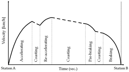
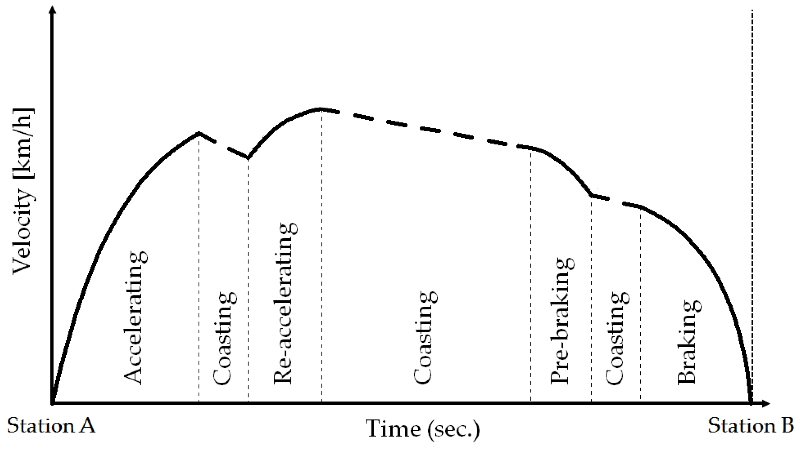
The electrical load characteristics of railway trains are determined by internal constraints based on the electrical specifications of the drive systems, such as traction motors and inverter, and topographical conditions, such as gradient and/or curvature sections. The internal constraint is used to derive the standard operating velocity curve between the two stations, as shown in Figure 1. In particular, within the allowable specification range of the driving system, the maximum rate of change in speed is set to 3.0 km/h/s and −3.5 km/h/s for acceleration and braking, respectively.
Figure 1.
Standard operating curve between two stations.
The gradient and/or curvature track conditions are reflected in the speed limit to prevent derailment of the train, resulting in a velocity profile deviating from the standard operating curve. These are the causes of the sudden acceleration and braking in the operating period other than the initial acceleration period and the final braking period. Combined with the train mobility characteristics, any peculiar power characteristic in substations is usually presented.
In this section, basic formulas of kinetic analysis for railway train motion are presented, taking into account the electrical specifications of the drive system and the topographical conditions of the track, and deriving the electrical load characteristics based on this analysis.
2.1. Kinetic Analysis Equations
The acceleration of the train is a physical quantity that must be calculated in order to calculate the speed and position of the wheel at every time step. Equation (1) shows the basic relations of total driving mass (mdr), effective traction force (FtET) and acceleration (atavg) of the train at a specific moment, time t. The total driving mass includes static mass (ms) and inertial mass (mtiner) as shown in Equation (2):
where atavg: acceleration (m/s2) during time period t; FtET: effective traction force (kN) during time period t and mdr: total driving mass (tonne):
where, ms: static mass (tonne) and miner: inertial mass (tonne).
The effective traction force is obtained by subtracting the train resistive force (FTR) from the motor traction force (FMT), as shown in Equation (3). The train resistive force is expressed by the sum of drag resistive force (FDR), curvature resistive force (FCV), and gradient resistive force (FGR), as shown in Equation (4). Each resistive force term can be expressed by Equations (5)–(7), respectively. The value of gradient resistive force might be negative according to the operating direction, and this is an important factor that causes a difference pattern in the load characteristics of the up-line and down-line trains.
where, FtET: effective traction force (kN) during time period t; FtMT: motor traction force (kN) during time period t and FtTR: train resistive force (kN) during time period t.
where, FtDR: drag resistive force (kN) during time period t; FtCV: curvature resistive force (kN) during time period t and FtGR: gradient resistive force (kN) during time period t.
where, α, β: kinetic friction coefficient ( ), (s/m); vtavg: average velocity of the railway train (m/s) during time period t; ag: gravitational acceleration 9.8 (m/s2) and γ: air friction coefficient (tonne/m):
where, k: curvature friction coefficient (m) and R: radius of curvature (m)
where g: gradient of the track (‰).
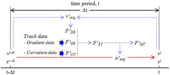
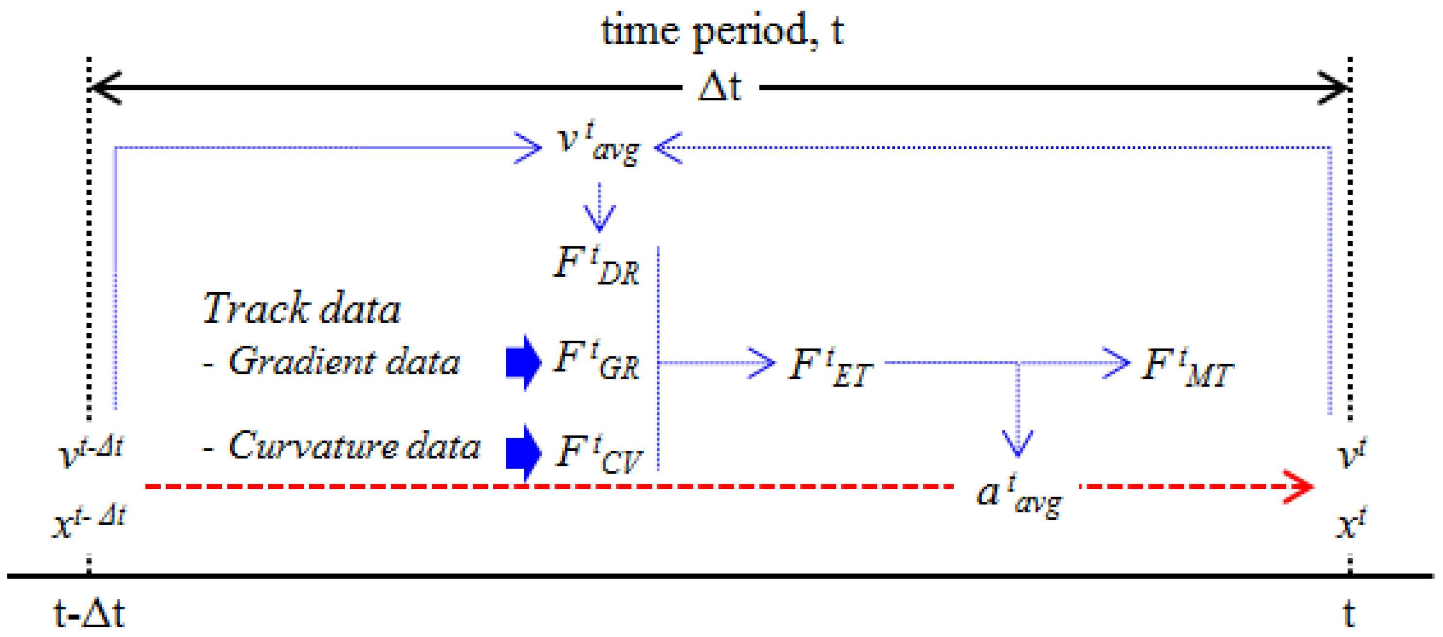
The effective traction force, which is derived in Equation (3) using each resistive force from Equations (5)–(7), is used to calculate the average acceleration (atavg) in Equation (1). As shown in Equations (8) and (9), this acceleration value applied to the train during time step (∆t) is applied to update the train speed and location from those values at the previous step:
where, vt: train velocity (m/s) at time t; vt−∆t: train velocity (m/s) at time t − ∆t and ∆t: simulation time step (s).
where, xt: location (m) of the train at time t and xt−∆t: location (m) of the train at time t − ∆t.
The curvature resistive force and gradient resistive force are independent of train velocity, but drag resistive force is affected by velocity change during ∆t, so the average of initial and final velocity of time period t should be applied to derive a more accurate acceleration value, as shown in Figure 2.
Figure 2.
Iterative process to update the velocity and location of the train.
2.2. Electrical Power Analysis Equations
Railway trains that operate in an urban railway system with an inter-station distance of about 1 km have three modes of operation: acceleration, coasting and braking. In the section on coasting, only natural deceleration due to the three kinds of train resistive force is considered, and it is a section where there is no consumed or regenerative energy, that is, zero electrical power.
From the derived motor traction force in Equation (3), the mechanical power can be calculated as shown in Equation (10) since the work is the integral value of the force with respect to displacement and the power is the derivative of work with respect to time:
where Ptmech: mechanical power (kW) during time period t.
In the section on acceleration with positive value of motor traction force, in consideration of the efficiency in the electric drive system (C/I, motor) and the mechanical drive system (gear box) in the train, the electric power for performing the mechanical demand operation must be calculated by applying the reciprocal of the efficiency of each apparatus, as shown in Equation (11):
where, Pttrac: electrical tractive power (kW) during time period t; ηgear: efficiency of gear box; ηinv: efficiency of C/I and ηMT: efficiency of the traction motor.
For the section on braking with negative value of motor traction force, since the regenerative power goes back into the catenary system through the electrical and mechanical drive apparatus, the electric power for braking is calculated as shown in Equation (12):
where Ptregen: electrical regenerative power (kW) during time period t.
As a result, considering auxiliary power (Paux) such as lighting, air conditioning, heating, communication equipment and controller, the railway train has three electrical powers according to the operation modes, as shown in Equation (13):
where, Ptveh: train power (kW) during time period t and Paux: auxiliary power (kW).
3. Optimal Design of ESS Specifications for WRT
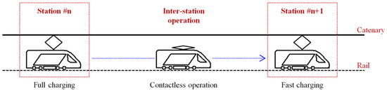
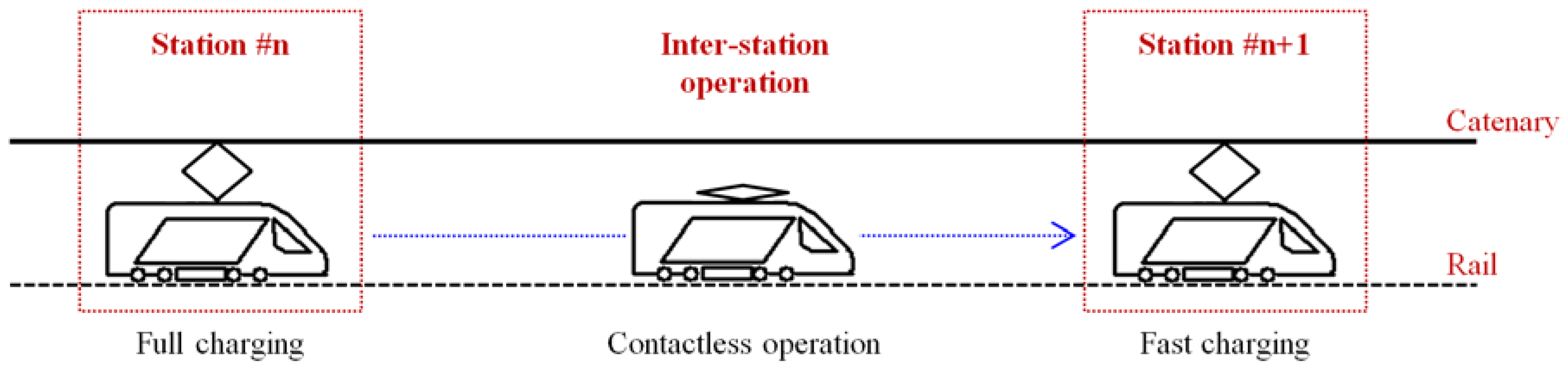
The power and storage capacity of a typical on-board energy storage system (ESS) focuses on the handling of regenerative power to improve energy efficiency and minimize system loss, but those of the ESS mounted on the WRT considered in this paper should be determined to be at a level that enables inter-station operating without catenary contact because it drives without contact to the catenary and charges the energy storage only at the platform of the next station, as shown in Figure 3. That is, the moving WRT is electrically isolated from the feeding system and it operates as an electrical load only at the platform during a stop.
Figure 3.
Operation scheme of wireless railway train (WRT).
3.1. Optimal Power and Storage Capacity Estimation
During motion, that is, in an electrically isolated state, the energy required for acceleration and the regenerative energy generated during braking should be handled only by the energy storage mounted on the train. This means that an ESS with a storage capacity greater than the maximum energy required in the most severe driving conditions must be considered. Here, the most severe condition indicates the maximum static mass condition, that is, the maximum passenger boarding condition, which is reported as 30% of the train’s mass. Considering the severe driving condition and additional devices related to the ESS, such as the storage power conversion system (PCS) and the energy storage packs (ESPs), the static mass applied to the formulas in Section 2 is modified, as shown in Equation (14):
where, mveh: mass (tonne) of railway train; mpsn: mass (tonne) of maximum passengers; mPCS: mass (tonne) of storage PCS and mESP: mass (tonne) of ESPs.
Assuming that it takes tmax to travel from the first station to the last station, the power capacity of the storage PCS must be greater than the maximum absolute value of the train power to implement the required acceleration or braking performance, and this can be expressed in Equation (15):
where, PPCS: power capacity (kW) of the storage PCS and tmax: total time (s) to travel whole railway track.
Assuming the whole railway track consisted of m stations, the optimal storage capacity can be estimated at the section where the depth of discharge is the greatest among the m − 1 sections. Based on the load characteristics from Equation (13), the variation in the amount of energy stored in the ESS can be calculated as in Equation (16):
where, Etsto: remaining energy (kWh) in ESS at time t; Et−∆tsto: remaining energy (kWh) in ESS at time t − ∆t; ηPCS: efficiency of PCS; 1/3600: scale factor for unit conversion from Joule to Wh.
The optimum storage capacity of a storage device required for reliable driving of a WRT makes the remaining amount zero at the maximum depth of the discharge state. Given that this value cannot be solved algebraically and is a value obtained through iterative calculations, the maximum difference between the minimum remaining energy and the storage capacity applied in each iteration step, as shown in Equation (17), is applied to the next iteration step as an optimal capacity:
where, Eopt (k): optimum storage capacity (kWh) at kth iteration step; Eopt (k − 1): optimum storage capacity (kWh) at k − 1th iteration step.
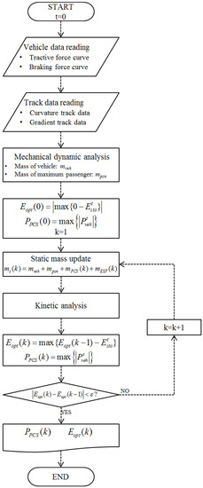
Figure 4 shows a flowchart of an iterative algorithm to solve the optimal storage capacity. The mass update process in the flowchart reflects the mass of the energy storage pack in Equation (18) and the storage PCS in Equation (19):
where, mESP (k): total mass (tonne) of ESP at kth iteration step; muESP: mass of ESP per unit storage capacity (tonne/kWh):
where, mPCS (k): total mass (tonne) of PCS at k-th iteration step; muPCS: mass (tonne) of 1000 kW unit PCS; PPCS (k): PCS power capacity (kW) at k-th iteration step; PuPCS: power capacity of unit PCS (=1000 kW) and [ ]: gauss function.
Figure 4.
Flowchart to find optimal power and storage capacity.
3.2. Storage Charging Characteristic at Platform during Stop
After arriving at the station, the pantograph is lifted up to be electrically connected to the catenary and to charge the storages. Then the charger makes the storage charged with the constant charging current (Icha) until the amount of energy used in the previous inter-station section is charged. The charging current can be determined as in Equation (20). Considering pantograph lifting up and down times of 2 s each during 30-s dwell times, the effective time for charging is about 25 s, and the charging current for full-charging can be calculated as shown in Equation (20). In Equation (20), the voltage value, Vminsto, means the storage voltage with the lowest remaining energy at the start of charging at each station:
where, Csto: capacitance (F) of supercapacitor storage; Icha: charging current (A); Vmaxsto: storage voltage (V) at full-charged state; Vminsto: storage voltage (V) at lowest-charged state and tcha: maximum available time (s) for charging.
3.3. Modified Electrical Load Characteristic
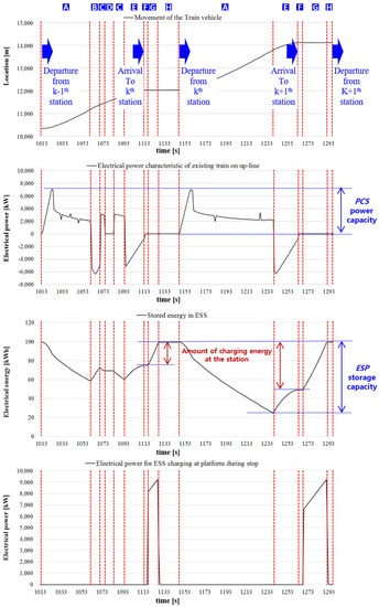
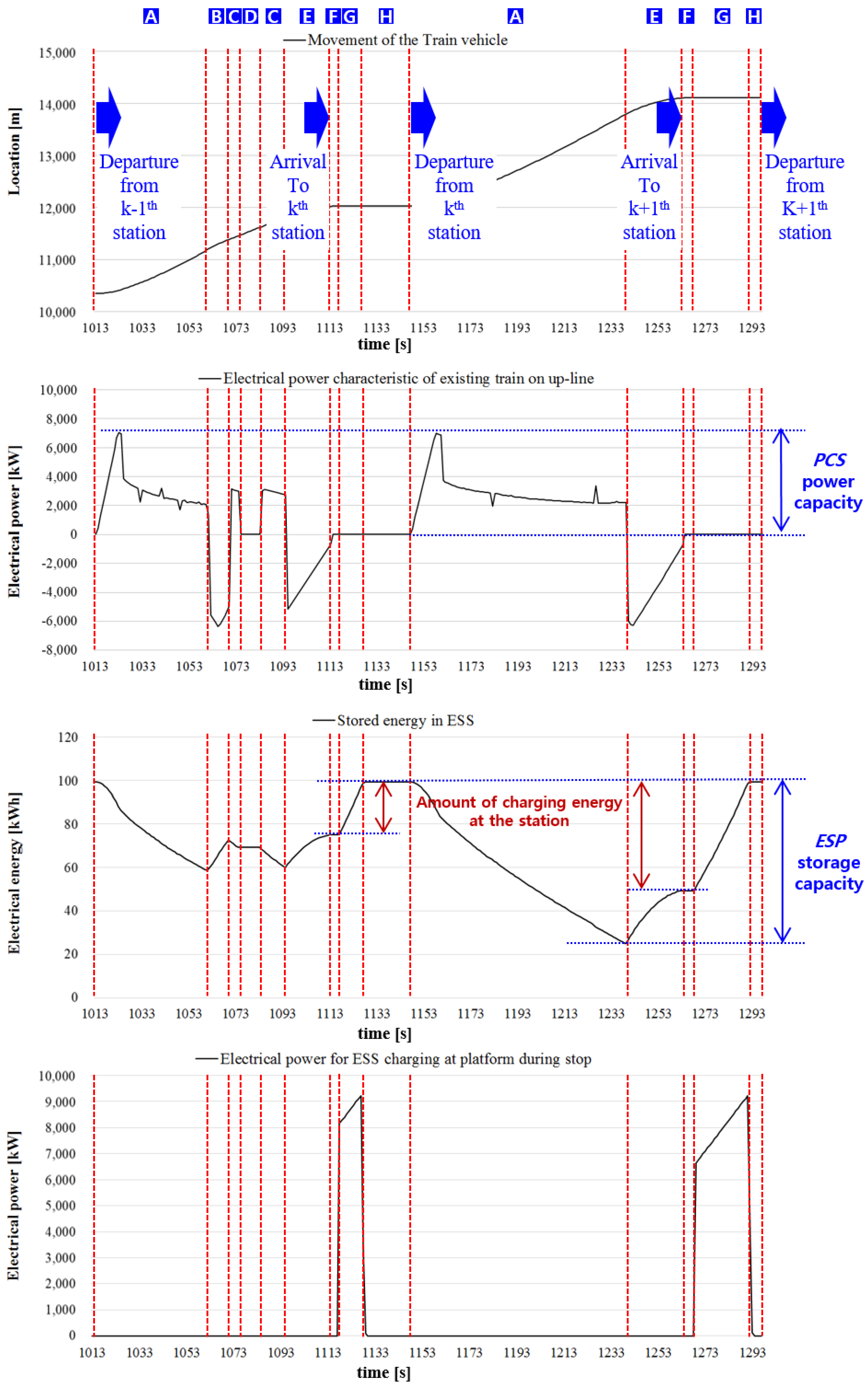
Since the WRT is operated in such a manner that it is isolated from the feeding system during driving and connected to charge storage at the platform during stops, the electrical load characteristic of the WRT is completely different from the load of the existing train. Figure 5 shows graphs for location of the train, electrical load from kinetic analysis, variation of remaining energy in the WRT storage, and modified electrical power characteristic of the WRT for two inter-station sections. That is, from the viewpoint of the feeding system, the WRT has values as an electrical load only during charging at the platform and 0 value in other states. Physical operation for each section is as follows:
Figure 5.
Operation mode of the railway train (location of the vehicle, power characteristics of the existing train, stored energy of the WRT storage, power characteristics of the WRT).
- State A
- Departure and initial accelerating: At the start of ‘State A’, the railway train departs to the next station. During this state, the ESS provides energy for accelerating. At this time, the WRT is electrically isolated from the feeding system and the electrical load for the feeding system is zero.
- State B
- Artificial braking by topographical track condition: Due to the curvature or gradient track condition, artificial braking may occur during driving. It can be seen that the regenerative energy generated at this time is charged by the storage and the stored energy increases.
- State C
- Re-acceleration: After artificial braking, there is a re-acceleration operation to increase the train velocity to within the normal driving velocity range.
- State D
- Coasting: This state is for the inertia operation. Generally, natural deceleration due to driving resistance occurs, but velocity may increase on some negative gradient track.
- State E
- Braking for arrival: A large amount of regenerative energy is usually generated, and the storage has the largest charge amount. At the end of ‘State E’, the WRT arrives at the station and starts to charge.
- State F
- Pantograph lifting-up: The pantograph is lifted up for storage charging. This takes around 2 s. At the end of ‘State F’, the WRT is electrically connected to the feeding system.
- State G
- Storage charging with constant current mode: The charging controller charges the storage with the constant charging current up to the full-charged state. During ‘State G’, the feeding system supplies electrical power to the WRT through the pantograph connected to the catenary. Charging operation lasts for up to 25 s.
- State H
- Pantograph lifting-down: After full charging at the end of ‘State G’, the pantograph takes several seconds to come down. At the end of ‘State H’, the WRT is electrically separated and departs to the next station.
4. Case Studies
The case studies have been carried out to analyze how much energy saving and peak power reduction can be achieved with the WRT on which an optimally designed energy storage system is mounted. It is based on the track data of the actual service route and the driving system specifications of the actual service train.
4.1. System Data
The route consists of 19 stations and five substations with rectifiers for converting AC to DC. Table 1 shows sets of operational data, structural data and electrical data. Curvature and gradient data of the track is presented in Appendix A and Appendix B.
Table 1.
System data of the Seoul Metro Line.
4.2. Optimal Power and Storage Capacity of the Storage on the WRT
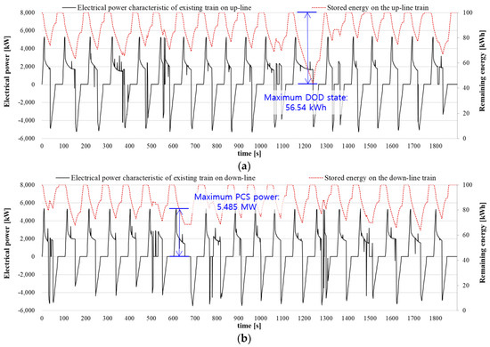
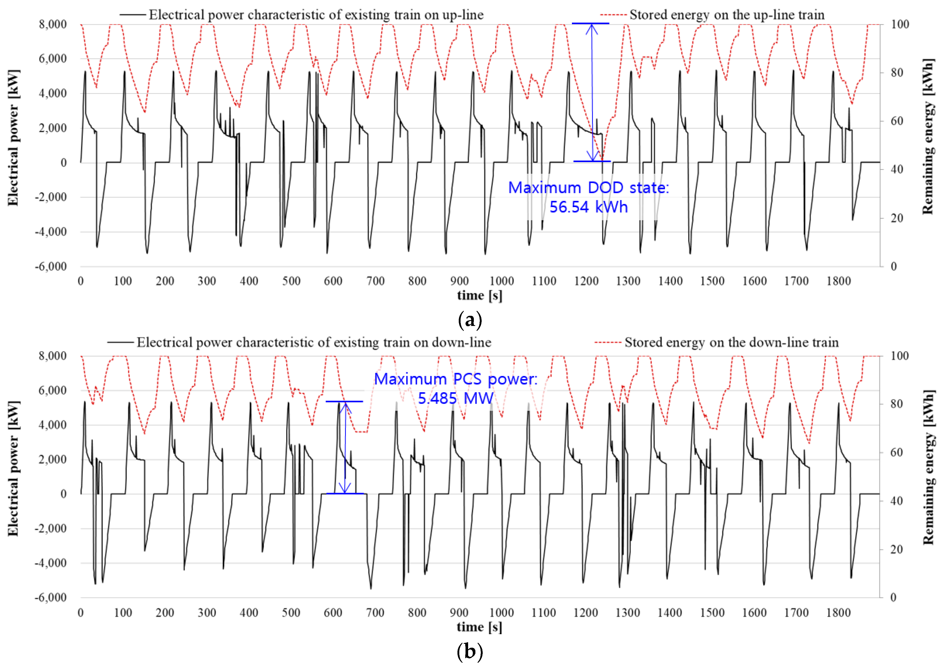
The initial value of power and storage capacity is calculated based on the results of the kinetic analysis of the train, including the mass of the train and the passengers only. Assuming the virtual 100 kWh storage, the maximum Depth of Discharge (DOD) of 56.54 kWh occurs in the 12th inter-station section in the upward direction and the maximum capacity of 5.485 MW occurs in the 7th inter-station section in the downward direction, as shown in Figure 6a,b, respectively. In particular, assuming supercapacitor storages which have only 75% of the stored energy as the available energy, the storage capacity gets to 4/3 times of the calculated required energy. That is, from the analysis results at the iteration Step 0, 6 (six) 1000 kW unit PCSs (for 5.485 MW PCS power) and 75.39 kWh (4/3 times of 56.54 kWh) are estimated, and these values are applied to the next step. From these results, the train load characteristic can be derived with the updated mass reflecting the mass of the energy storage packs and the PCS.
Figure 6.
Electrical power characteristics and stored energy variation for the up- and down-line train at iteration step 0. (a) up-line train; (b) down-line train.
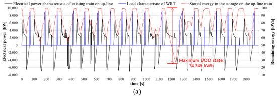
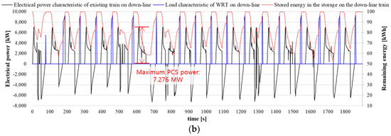
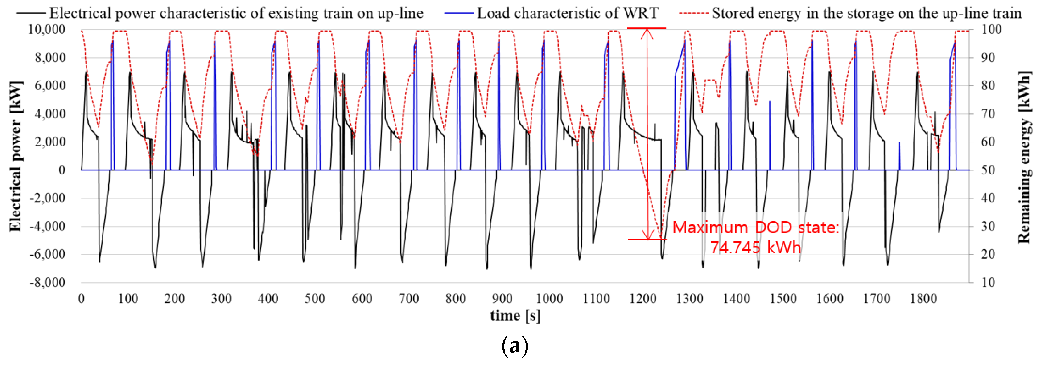
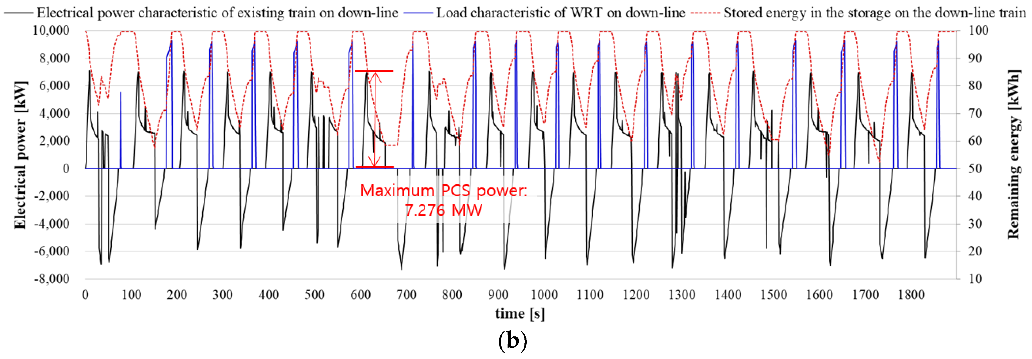
Table 2 shows the results of each iteration step. As the power capacity of the PCS and the storage capacity of the energy storage pack increase, the driving mass increases and, finally, the total mass converges to 352.7 tonnes. Then the optimal power and storage capacity of the storage set is estimated to be 7.276 MW and 99.66 kWh, which is effective energy of 74.745 kWh. Figure 7a,b show the final electrical power characteristic and modified load characteristic considering charging and discharging operation of the storage system.
Table 2.
Results of each iteration step for power and storage capacity optimization (muESP = 0.7 tonne/kWh, muPCS = 2.1 tonne).
Figure 7.
Final electrical power characteristics, remaining energy, and modified load characteristics for the up- and down-line driving train at final iteration step. (a) up-line train; (b) down-line train.
4.3. Peak Headway Operating Condition
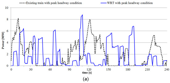
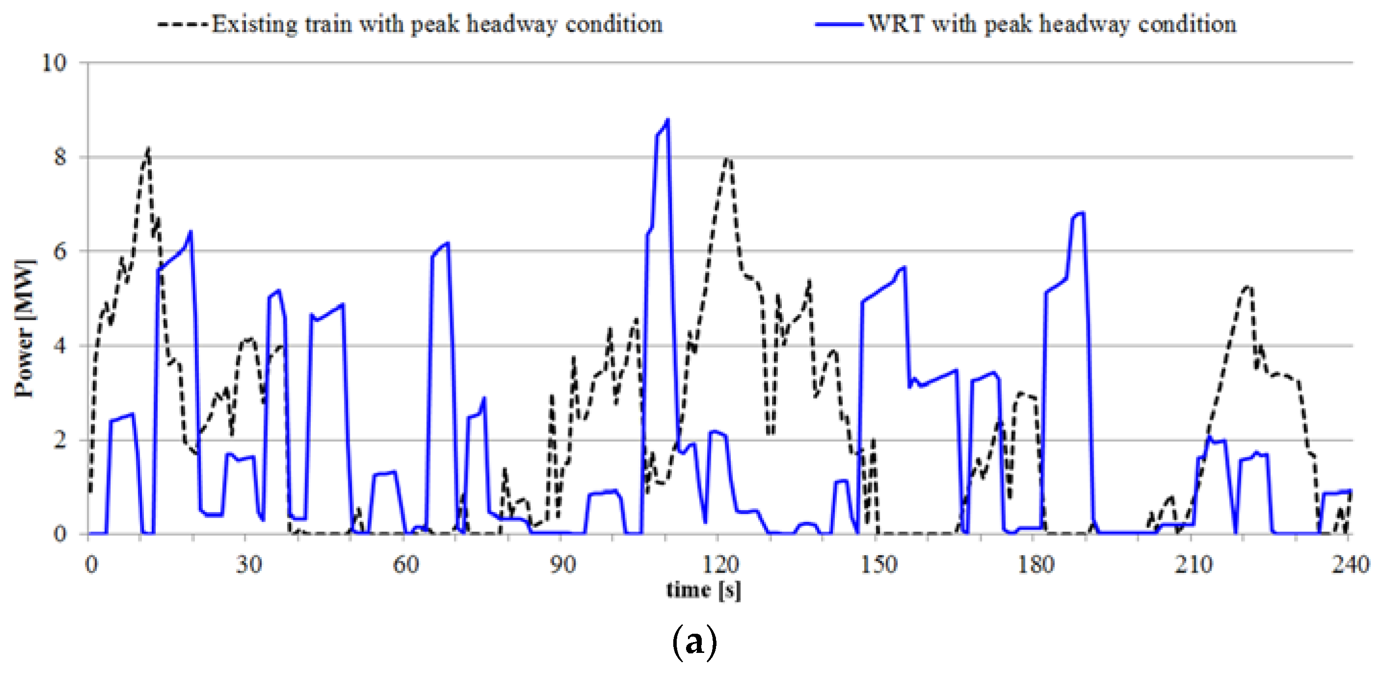
The peak headway during rush hour is set to 240 s and a maximum of 8 trains in each direction are driven. Based on these operating conditions, comparison studies of electrical performance of each substation according to the operation of the WRTs and the existing trains have been carried out based on the DC electric railway powerflow analysis method [14]. Figure 8 shows the power supplied at each substation by the WRTs and existing trains’ operation. From the perspective of energy, although the power consumption increases due to the increased weight, since the regenerative energy is handled by the train itself, the total effective energy supplied from the substation can be lowered.
Figure 8.
Results of substation power for the peak headway condition. (a) Electrical power of Substation 1; (b) Electrical power of Substation 2; (c) Electrical power of Substation 3; (d) Electrical power of Substation 4; (e) Electrical power of Substation 5.
Table 3 and Table 4 show the comparison results of the power simulation for the peak headway condition. Comparing the simulation results of each type of train, it can be seen that the maximum power is at a similar level except for substation 5. In substation 5, the maximum power is about double, but it can be handled with the existing electrical facilities. The application of WRTs also has the advantage of reducing energy consumption. Total supply energy is analyzed as 88.88% compared with the case of an existing train. This is because not only is the required energy amount reduced by increasing the utilization rate of the regenerative energy but also the system loss is reduced due to the smaller load current.
Table 3.
Power simulation results for railway substation at peak headway condition.
Table 4.
Train energy analysis results at peak headway condition.
4.4. Non-Peak Headway Operating Condition
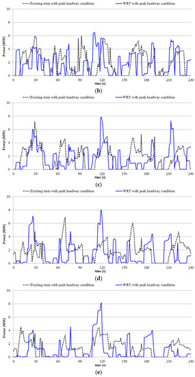
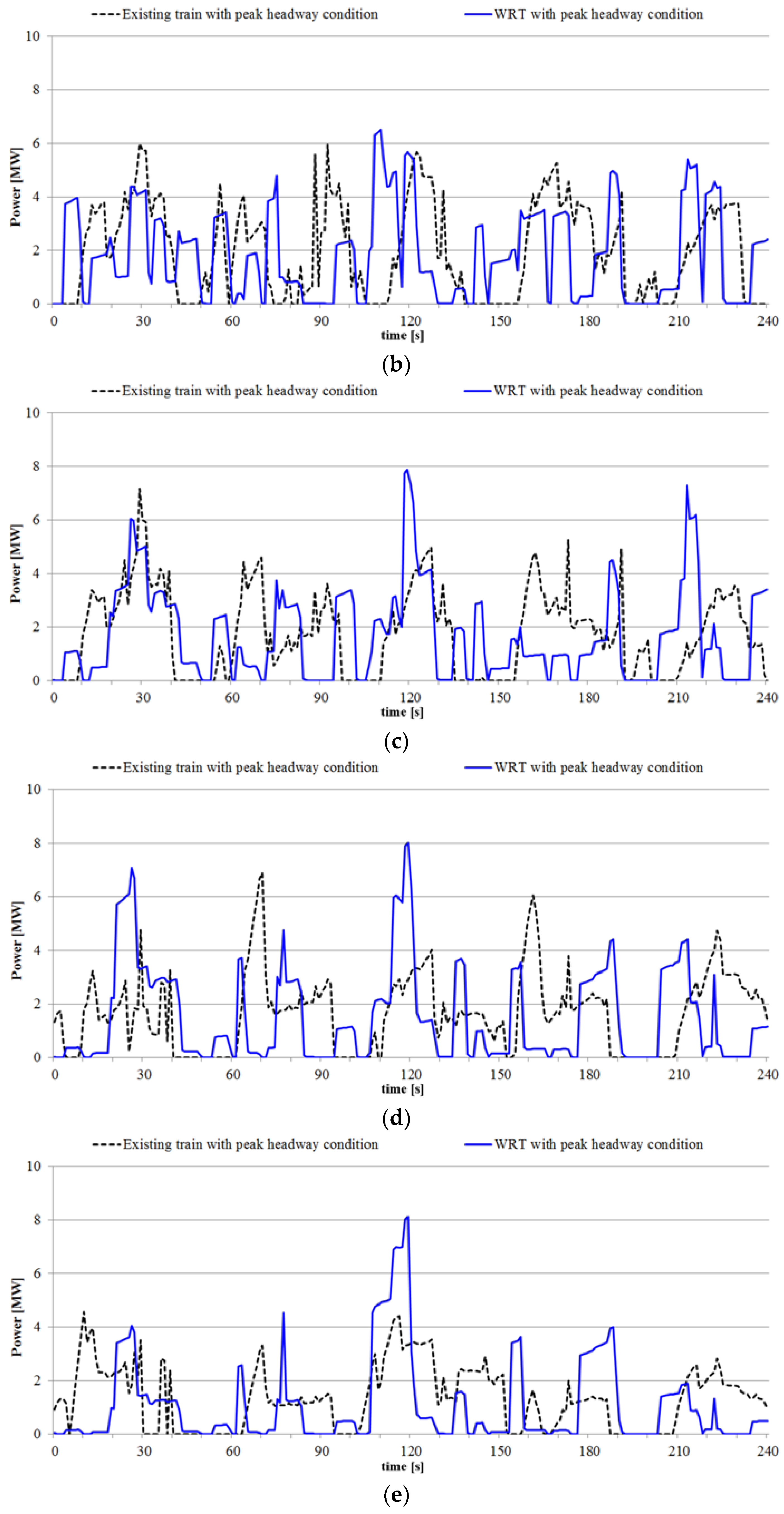
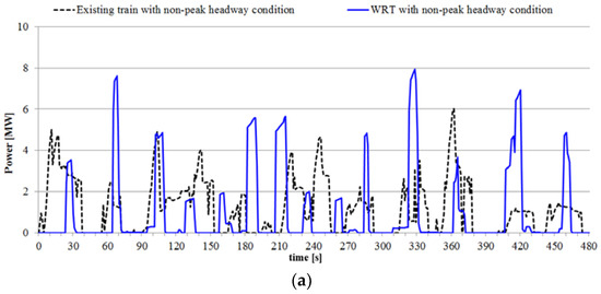
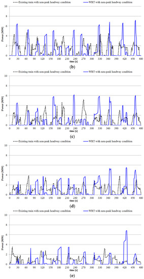
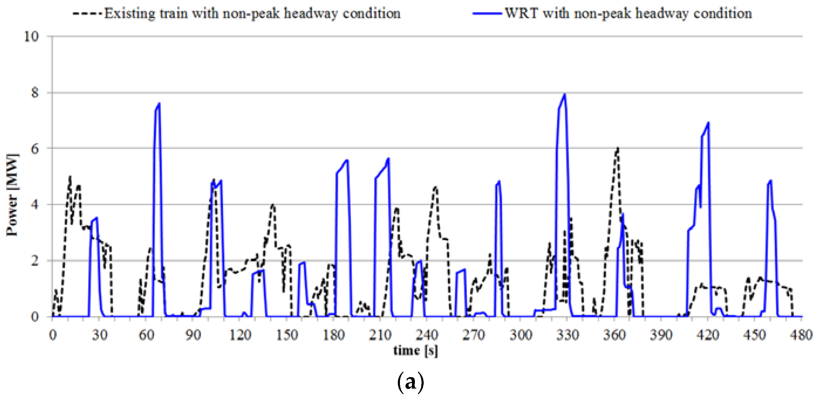
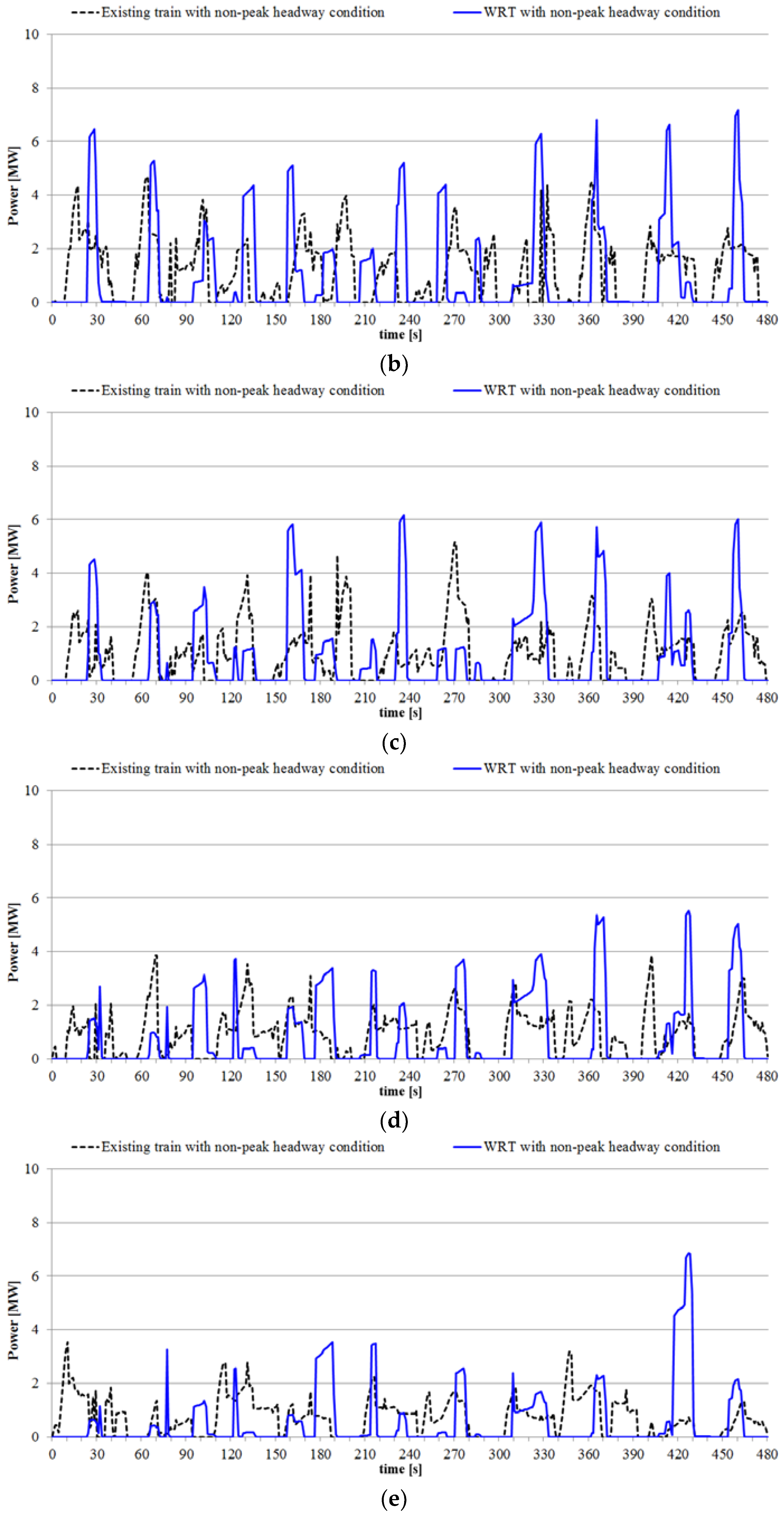
At times other than the rush hour, the headway time of 480 s is set and a maximum of four trains in each direction operate. For the non-peak headway condition, the simulation results of electrical power for each substation are shown in Figure 9a–e. The peak power values of the substations are slightly increased, but those values are under the system capacity of the existing electrical facilities.
Figure 9.
Results of substation power for the non-peak headway condition. (a) Electrical power for Substation 1; (b) Electrical power for Substation 2; (c) Electrical power for Substation 3; (d) Electrical power for Substation 4; (e) Electrical power for Substation 5.
Table 5 and Table 6 show the comparison results of the power simulation for the non-peak headway condition. Since the electrical load and simulation time at the non-peak headway condition are half and twice that of the peak headway operating condition, respectively, it is easy to expect that total supplied energy will be calculated at a similar level. However, in the case of existing trains, the difference between the two values is considerably large. This is because the utilization rate of regenerative energy is lowered due to the lower number of trains which usually consume that energy.
Table 5.
Power simulation results for railway substation at non-peak headway condition.
Table 6.
Train energy analysis results at non-peak headway condition.
5. Conclusions
In order to verify the electrical merits of the WRT application, this paper proposed a method for estimating the optimum power and storage capacity of the energy storage system mounted on the WRT and presented comparative analysis results of power simulation for existing trains and WRT. Since the WRTs dealt with in this paper apply the contactless method during motion, the proposed optimal capacity estimation method finds the optimal power capacity capable of coping with the demand operation of the train considering the increased driving power by the additional mass of PCS and energy storage packs.
Through the case studies, the electrical performance of WRTs designed to improve the energy-sustainability by maximizing the utilization of regenerative energy and minimizing the system loss has been verified. In terms of electrical performance, the advantages of the WRT application include the full utilization of regenerative energy for high energy-sustainability, and driving energy and system loss reduction for reduced operating cost without any additional electrical facilities in the railway substation. In addition to its electrical benefits, there are several other advantages, such as preventing mechanical wear of the catenary, enhancing reliability of the electrical device due to electrical arc removal, enhancing operational reliability of the train against system failure, increasing transportation capacity without additional power equipment, etc.
Despite maximizing the utilization rate of regenerative energy, the reason why the energy efficiency improvement effect of the WRT application stays at around 20% is because of the increase in the driving mass of about 33% by the energy storage mount. In other words, the greater energy saving can be expected through the weight reduction of the storage devices, that is, improvement in the energy density of the ESPs and power density of the PCSs. Also, based on the estimation of the overall benefits, including the electrical benefits, it is expected that more accurate cost/benefit analyses for WRT applications will be achieved.
Acknowledgments
This study was supported by R&D Project of Korea Railroad Research Institute.
Author Contributions
Jaewon Kim conceived and designed the main concept; Jaewon Kim, Joorak Kim and Hansang Lee performed power simulation; Jaewon Kim, Changmu Lee and Gildong Kim analyzed train energy data; Jaewon Kim and Byongjun Lee wrote the paper.
Conflicts of Interest
The authors declare no conflict of interest.
Appendix A
Table A1.
Track Curvature Data.
Appendix B
Table A2.
Track Gradient Data.
References
- Song, Y.; Ouyang, H.; Liu, Z.; Mei, G.; Wang, H.; Lu, X. Active control of contact force for high-speed railway pantograph-catenary based on multi-body pantograph model. Mech. Mach. Theory 2017, 115, 35–59. [Google Scholar] [CrossRef] [Scilit]
- Vo Van, O.; Massat, J.-P.; Balmes, E. Waves, modes and properties with a major impact on dynamic pantograph-catenary interaction. J. Sound Vib. 2017, 402, 51–69. [Google Scholar] [CrossRef] [Scilit]
- Schirrer, A.; Aschauer, G.; Talic, E.; Kozek, M.; Jakubek, S. Catenary emulation for hardware-in-the-loop pantograph testing with a model predictive energy-conserving control algorithm. Mechatronics 2017, 41, 17–28. [Google Scholar] [CrossRef] [Scilit]
- Wang, Y.; Liu, Z.; Mu, X.; Huang, K.; Wang, H.; Gao, S. An Extended Habedank’s Equation-Based EMTP Model of Pantograph Arcing Considering Pantograph-Catenary Interactions and Train Speeds. IEEE Trans. Power Deliv. 2016, 31, 1186–1194. [Google Scholar] [CrossRef] [Scilit]
- Kuo, M.-T.; Lo, W.-Y. Magnetic Components Used in the Train Pantograph to Reduce the Arcing Phenomena. IEEE Trans. Ind. Appl. 2014, 50, 2891–2899. [Google Scholar] [CrossRef] [Scilit]
- Gershman, I.S.; Gershman, E.I.; Mironov, A.E.; Fox-Rabinovich, G.S.; Veldhuis, S.C. On Increased Arc Endurance of the Cu-Cr System Materials. Entropy 2017, 19, 386. [Google Scholar] [CrossRef] [Scilit]
- Jung, N.-G.; Lee, H.; Kim, J.-M. A Study on Characteristic of Power Conversion System in Electric Railway Vehicle According to Contact Loss in Feeding System Considering Characteristic of Rigid Bar. Trans. KIEE 2016, 65, 520–525. [Google Scholar] [CrossRef] [Scilit]
- Hwang, K.; Kim, D.; Har, D.; Ahn, S. Pickup Coil Counter for Detecting the Presence of Trains Operated by Wireless Power Transfer. IEEE Sens. J. 2017, 17, 7526–7532. [Google Scholar] [CrossRef] [Scilit]
- Li, S.; Liu, Z.; Zhao, H.; Zhu, L.; Shuai, C.; Chen, Z. Wireless Power Transfer by Electric Field Resonance and Its Application in Dynamic Charging. IEEE Trans. Ind. Electron. 2016, 63, 6602–6612. [Google Scholar] [CrossRef] [Scilit]
- Lee, S.B.; Ahn, S.; Jang, I.G. Simulation-Based Feasibility Study on the Wireless Charging Railway System with a Ferriteless Primary Module. IEEE Trans. Veh. Technol. 2017, 66, 1004–1010. [Google Scholar] [CrossRef] [Scilit]
- Kim, J.H.; Lee, B.S.; Lee, J.H.; Lee, S.H.; Park, C.B.; Jung, S.M.; Lee, S.G.; Yi, K.P.; Baek, J. Development of 1-MW Inductive Power Transfer System for a High-Speed Train. IEEE Trans. Ind. Electron. 2015, 62, 6242–6250. [Google Scholar] [CrossRef] [Scilit]
- Kim, J.H.; Lee, B.S.; Lee, J.H.; Lee, S.H.; Park, C.B.; Jung, S.M.; Lee, S.G.; Yi, K.P.; Baek, J. Conceptual Design and Operating Characteristics of Multi-Resonance Antennas in the Wireless Power Charging System for Superconducting MAGLEV Train. IEEE Trans. Appl. Supercond. 2017, 27, 3601805. [Google Scholar]
- De Boeij, J.; Lomonova, E.; Duarte, J. Contactless Planar Actuator with Manipulator: A Motion System without Cables and Physical Contact between the Mover and the Fixed World. IEEE Trans. Ind. Appl. 2009, 45, 1930–1938. [Google Scholar] [CrossRef] [Scilit]
- Lee, H.S.; Lee, H.M.; Lee, C.M.; Jang, G.S.; Kim, G.D. Energy Storage Application Strategy on DC Electric Railroad System using a Novel Railroad Analysis Algorithm. J. Electr. Eng. Technol. 2010, 5, 228–238. [Google Scholar] [CrossRef] [Scilit]
- Lee, H.; Song, J.; Lee, H.; Lee, C.; Jang, G.; Kim, G. Capacity Optimization of the Supercapacitor Energy Storages on DC Railway System Using a Railway Powerflow Algorithm. Int. J. Innov. Comput. Inf. Control 2011, 7, 2739–2753. [Google Scholar]
- Lee, H.; Jung, S.; Cho, Y.; Yoon, D.; Jang, G. Peak power reduction and energy efficiency improvement with the superconducting flywheel energy storage in electric railway system. Physica C 2013, 494, 246–249. [Google Scholar] [CrossRef] [Scilit]
- Jung, B.; Kim, H.; Kang, H.; Lee, H. Development of a Novel Charging Algorithm for On-board ESS in DC Train through Weight Modification. J. Electr. Eng. Technol. 2014, 9, 1795–1804. [Google Scholar] [CrossRef] [Scilit]
- Iannuzzi, D.; Ciccarelli, F.; Lauria, D. Stationary ultricapacitors storage device for improving energy saving and voltage profile of light transportation networks. Transport. Res. C Emerg. Technol. 2012, 21, 321–337. [Google Scholar] [CrossRef] [Scilit]
- Arboleya, P.; Bidaguren, P.; Armendariz, U. Energy Is On Board: Energy Storage and Other Alternatives in Modern Light Railways. IEEE Electrif. Mag. 2016, 4, 30–41. [Google Scholar] [CrossRef] [Scilit]
- Xiao, Z.; Sun, P.; Wang, Q.; Zhu, Y.; Feng, X. Integrated Optimization of Speed Profiles and Power Split for a Tram with Hybrid Energy Storage Systems on a Signalized Route. Energies 2018, 11, 478. [Google Scholar] [CrossRef] [Scilit]
- Ceraolo, M.; Lutzemberger, G. Stationary and on-board storage systems to enhance energy and cost efficiency of tramways. J. Power Sources 2014, 264, 128–139. [Google Scholar] [CrossRef] [Scilit]

© 2018 by the authors. Licensee MDPI, Basel, Switzerland. This article is an open access article distributed under the terms and conditions of the Creative Commons Attribution (CC BY) license (http://creativecommons.org/licenses/by/4.0/).