Abstract
Gaze detection requires estimation of the position and the relation between user’s pupil and glint. In this research paper, a Gaze Direction Estimation (GDE) model, a feature based shape method has been proposed for the comparative analysis of two standard edge detectors canny and sobel for estimating position of the glint coordinates and subsequently gaze direction based on the different human eye images dataset. The results indicate fairly good percentage of the cases where the correct glint coordinates and correct gaze direction quadrants have been estimated by the canny edge detector as it performs better than the sobel operator in most cases. These results can further be used for improving the accuracy and performance of different eye gaze based controlled systems.
Introduction
Eye gaze, by replacing the computer mouse and keyboard as the input method, provides a more immediate way of communication for the selection of any task, icon or menu by the user. Communication through the direction of eyes is faster than any other mode of human communication (Bednarik, Gowases, & Tukiainen, 2009; Sibert & Jacob, 2000; Sharma & Abrol, 2013). Gaze based system requires the estimation and detection of gaze with high accuracy so as to identify the region of interest (RoI) in the input image. Based on the detected position of RoI, the gaze direction can be used to activate any icon or object on the screen.
Gaze estimation is generally done in relation to gaze direction of the user’s eye position and movements which may combine specific eye movements (Nakazawa & Nitschke, 2012; Kim & Ramakrishna, 1999; Mollenbach et al., 2013).
Gaze based applications may adapt their behavior based on user’s visual attention. If the application is aware of the user’s current or visual attentive state, it will help by responding in a more natural way so as to estimate gaze to find out where the user is looking or what the target is (Jacob, 1991).
The light from the surrounding environment is reflected by the cornea of the human eye. Several such reflections of the light occur on the boundary between the lens and the cornea, producing different purkinje images. The first purkinje image, the brightest corneal reflection is often referred to as the glint (Hansen & Ji, 2010). In terms of image, the glint can be regarded as the highest possible grayscale value located within pupil region or on its circumference. The glint is much brighter than the rest of the eye image and thus can be tracked and detected easily for finding the gaze detection and direction. The direct look into the camera reflects the glint approximately at the pupil’s center. The glint center drops below the pupil center when looking directly above the camera. The glint moves to the bottom left of the pupil center while looking to the left and vice versa. The direction of gaze is generally estimated by mapping reference point of the glint vector and the center of the pupil (Zhu & Ji, 2004; Petkovsek et al., 2012; Bialkowski et al., 2007). The light source closer to the camera axis brightens the pupil whereas the light away from the camera axis brightens the glint and the image shows a dark pupil. Current gaze estimation methods are mostly feature based shape method, working on extracted local features (Hansen & Ji, 2010). These features include the outline of the eye, iris, contours, pupil, eye corners, and corneal reflections or glint etc. from the eye image (Djeraba, 2010; Ohtani & Ebisawa, 1995; Ebisawa, 1998).
Analysis of the pupil and glint are relatively easier to find and can be formally related to gaze, making these the most popular approach for gaze estimation. The gaze direction can be determined by using only a single glint if the distance between the eye and the monitor is constant or keeping the head fixed with point of regard sources as centre of the pupil, centre of glint etc. These results can be generalized for eye gaze based systems, as observed by authors. The glint may change location when the head moves (Guestrin & Eizenman, 2006). However, in certain cases glint captured using camera with a light source may often locate near the centre or within the iris area (Choo et al., 2012; Song et al., 2005). Once the centers of the pupil and glint are obtained, it is possible to determine the direction of the user’s gaze (Sharma & Abrol, 2015c; Goni et al., 2004; Bates et al., 2005).
Different eye features like glint, pupil, iris etc. can be calculated using the edge detection operators. Edge detection in image processing reduces data storage besides retaining its topological properties. Different edge detectors may have different sensitivity to noise and smoothness values, ability to approximate the edges, different computational time and complexity. Applying an edge detector to an image may lead to a set of connected curves indicating the boundaries of objects, the boundaries of surface marking as well corresponds to the discontinuities in surface orientation (Lee, 2012). Variations in the threshold and other parameters of edge detectors generate different output images particularly to find the RoI (Rakesh, Chaudhuri, & Murthy, 2004). Various edge detectors like sobel, canny, prewitt, roberts, zerocross etc. can be used to detect edges and their orientations. It has been observed that sobel is sensitive to noise and also generates inaccurate results at times. The canny edge detector, however, is the optimal and more efficient edge detector. It uses Gaussian filter and is better especially in noise conditions than sobel. The limitation involves complex computations, more time consumption and producing poor edges for low contrast images (Nagaraju, Nagamani, Rakesh Prasad, & Sunitha, 2011; Maini & Aggarwal, 2009). Both the detectors require preprocessing like noise removal etc. of the images, appropriate thresholds and other parametric values for their working (Sharma & Abrol, 2012). Edge detectors also facilitate the extraction of morphological outlines from the digitized image. Using mathematical morphology, the input image is changed into a set for further processing. Morphological operation dilation causes objects to dilate or grow in size whereas erosion causes objects to shrink (Nagaraju, Nagamani, Rakesh Prasad, & Sunitha, 2011). Such morphological arithmetic operations are used for detecting, modifying, manipulating and separating the boundaries of RoI of the features present in the image.
The objective of the proposed Gaze Direction Estimation (GDE) model is to analyse the output resultant images for estimating position of the glint coordinates and subsequently the gaze direction based on the different human eye images dataset. The experimental and comparative analysis have been done using the two standard edge detectors canny and sobel by capturing the face images of different subjects. The proposed GDE model explores the glint position as RoI in the human eye to identify the gaze direction and thus can be classified as feature based shape method. The output images have been comparatively analyzed by adjusting different control parameters. The output of eye gaze is based on the detection of correct glint and thus mapping correct gaze quadrant. The outcome of the research work may be helpful in developing a simple and nonintrusive system for gaze based controlled systems. The main features of this method include cost effectiveness, use of ubiquitous hardware and software and simplified image capturing procedure.
The remainder of this paper is organized as follows: The literature review is presented in next section under heading Related work. The methodology of the proposed GDE model is explained in the Methodology section. The experimental results and discussion are described in the Results and Discussion section. The conclusion and further research directions are presented in the last section of the paper.
Related work
Different methods are being used to detect the RoI i.e., pupil, glint or iris for the eye gaze detection system. Some of the significant algorithms and models for pupil-glint mapping as presented by different researchers are discussed below.
A comparative analysis for the glint detection has been carried out on different single eye images. As observed by the authors, the complexity, space and time in the making of the eye gaze model can be reduced by using the edge detectors for eye gaze based systems. The proposed model can be used for improving and minimizing the interactivity time for enhancing the accuracy and performance by varying the number of processor affinities (Sharma & Abrol, 2015a).
Nakazawa et al. (Nakazawa & Nitschke, 2012) calculate the relative position of the gaze reflection point (GRP) with the four glints using mapping based pupil centre corneal reflection (PCCR) technique. A new gaze calibration procedure based on generalized regression neural networks (GRNN) is proposed by Zhu et al. (2004) for pupil glint detection and tracking, gaze calibration and gaze mapping with the changes of pupil images under different quadrants like left, front, right look of the face orientations. The methods proposed by Zhu et al. (2007) also use PCCR technique. A novel approach for eye detection using the variance projection function (VPF) has been proposed by Feng et al. (1998) to locate the landmarks of the human eye to detect the eye position and shape by using various edge detectors in the real eye images as well as human face images. A comparative analysis for the glint detection has been carried out using six standard edge detectors. It has been observed that out of the six detectors, canny and sobel detectors generate better results for finding the glint using different parameters (Sharma & Abrol, 2015b; Sharma & Abrol, 2015c). One time natural head movement and minimal calibration procedure is proposed for a new user. In another experiment, the effect of the distance from the camera on the gaze accuracy is analyzed. The results show that as the user moves away from the camera, the gaze resolution will decrease. Erdogmus et al. (Erdogmus & Dugelay, 2010) present an efficient method of extracting iris and eyelid using different edge detector techniques.
Gaze estimation algorithm is presented by Lewis et al. (2013) on pupil glint detection and tracking, gaze calibration and mapping to determine eye gaze position. Ohno et al. (Ohno, Mukawa & Yoshikawa, 2002) proposed another monocular novel eye gaze tracking system FreeGaze with a single light source, a calibrated camera and a single glint. The gaze position is computed accurately after the detection of the pupil and the centroid of the purkinje image from the captured image. The same algorithm is also used by Ohtani et al. (1995) based on the pupil detection technique using two light sources and the image difference method. In the proposed method, the pupil and glint images are detected by the costly hardware. The system has the image differentiator, the pupil detector and edge detector, the centroid detector and the glint edge detector and, therefore, has an add-on cost. The same method is further modified by Ebiswa (1998) by proposing a video-based eye gaze based pupil detection method using two light sources and the image difference method. It is observed that when the eye is directed to unusual positions from the camera, the glint comes out of the pupil image due to pupil constriction and yields a small dot.
Another model proposed by Blignaut (2013) works on the X and Y co-ordinates of the point of regard (PoR) and the pupil-glint vector. It has been observed that the normalization of the pupil-glint vectors and inter-pupil distance affects the accuracy of eye gaze and gaze distance. For better efficiency and accuracy, the gaze distance has to be controlled. A contact free eye gaze tracking system for gaze and facial pose computation is developed for monitoring driver’s vigilance by computing the vector defined by the pupil centre and a set of glints generated in the eye using iris radius by Perez et al. (2003). Although the algorithm minimizes the measurement error in the pupil glint vector, the system hardware is quite costly. Wang et al. (Wang, Sung & Venkateswarlua, 2005) estimate gaze using iris contours and only one eye using several morphological image processing operations for accurate gaze determination. The pupil center is located by ellipse fitting with the help of the glint in the dark pupil for detecting the local gaze direction using support vector regression for mapping relationship of the eye parameters to gaze point (Zhang et al., 2009).
Aniket et al. (Aniket & Dhanvijay, 2015) used blob detection method and image processing techniques to identify and study machine printed characters taking into consideration the pixel values as inputs. It is observed that the resultant image may contain noise or unwanted blobs or holes caused by noise or lighting conditioning that may interfere with the detection of RoI. Although blob analysis takes lesser time than edge detection but edge detection is more robust and simpler to use. Also segmentation may not be required in edge detection algorithm (Sookman, 2006).
It is evident from the literature review that the glint based detection is an important method for the gaze detection. However, the accuracy of detection depends on the correct estimation of the coordinates of the glint and subsequent gaze directions. The edge detection methods and morphological image processing operations can be used for improving gaze determination. Also, the extra hardware, computational cost and complexity, detection of pupil etc, different light sources, extra cameras etc. required for the eye gaze based systems can further be reduced by selecting the best of the two eye images using the proposed model.
It is essential that an eye gaze system should be able to generate required contours and edges while singling out the glint and its relative location for better precision. Images with better resolution may further improve the precision of glint detection. The appropriate processing for effective estimation of the gaze is required by varying the different thresholds and other control parameters resulting in generation of variety of edges, contours and other regions of interest in the input image. It is quite significant to identify the set of effective parameters with the edge detectors for the analysis and generation of required output. Further, it has been observed that comparatively canny and sobel edge detectors give better results.
Methodology
The objective of the proposed GDE model is to detect the glint coordinates and subsequently to estimate the gaze direction.
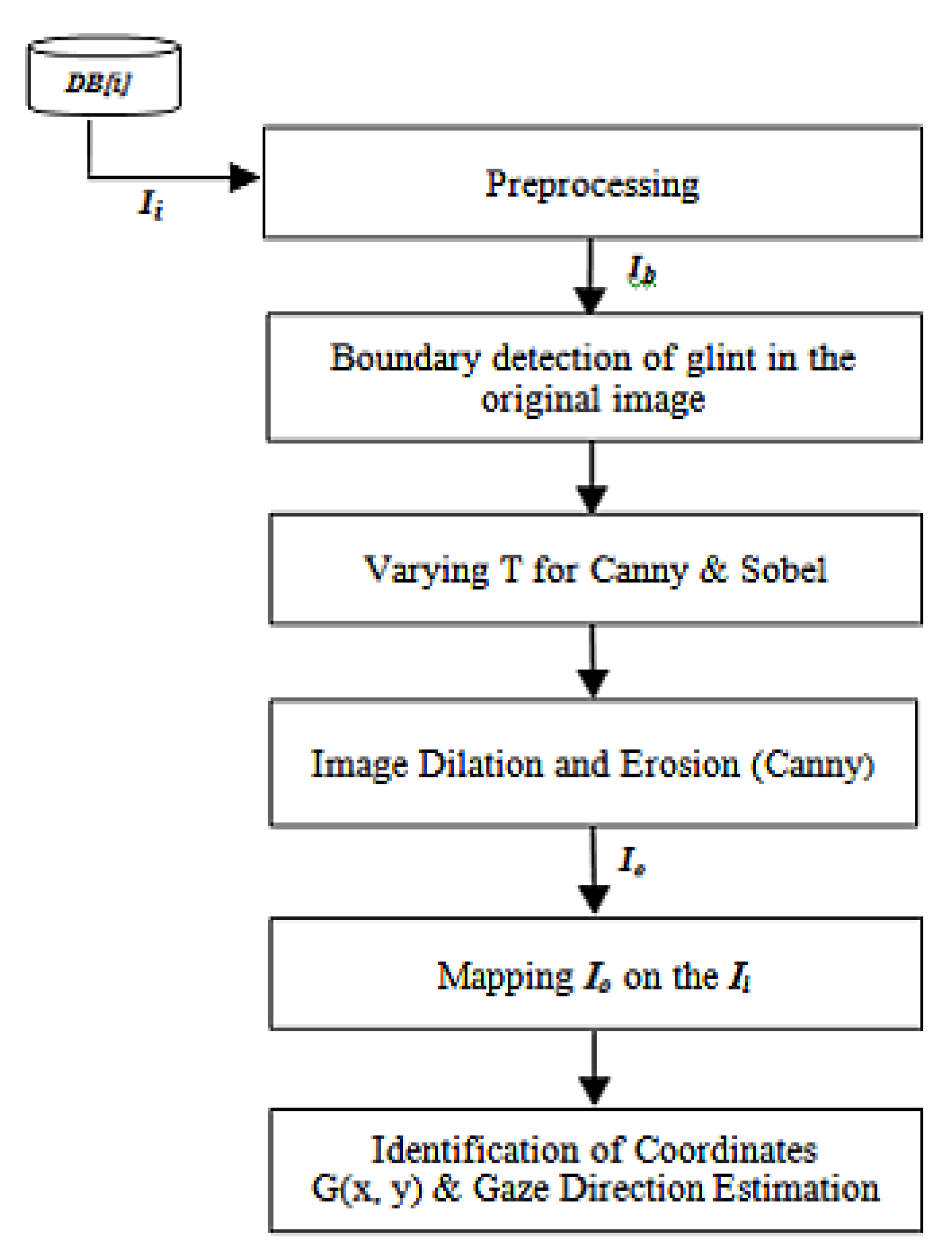
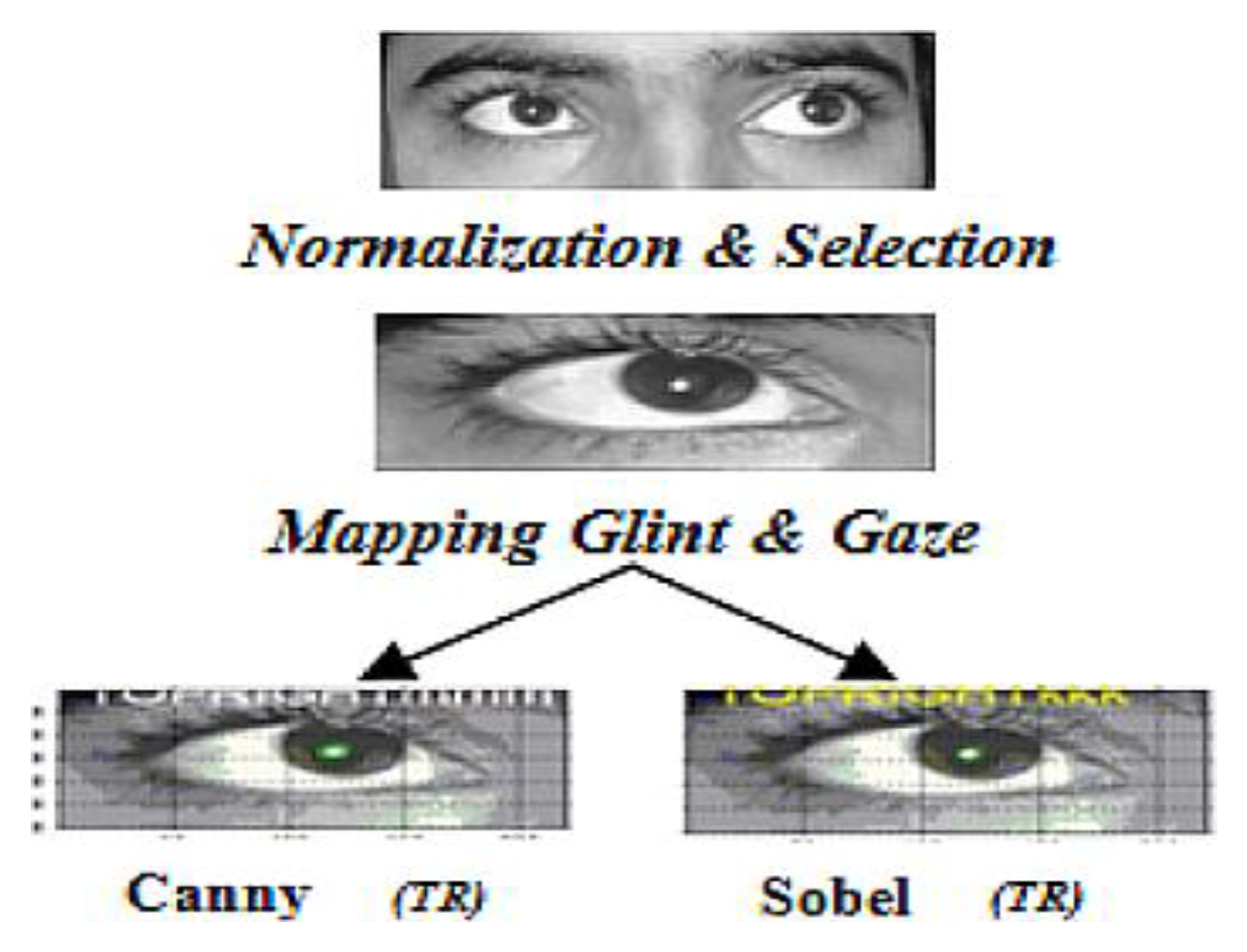
The proposed model has also been used to comparatively analyse the working of two standard edge detectors canny and sobel using image dataset generated by capturing the face images of twenty different subjects. The complete workflow of this GDE algorithm is given in Figure 1. Total one hundred input images have been taken for creating an image database DB[i] which consists of images of both male and female, all with normal eye vision in the ratio of 14:6. The age group of the subjects lies within the range of 20-40 years. Care has been taken to minimize any other incident light falling on the pupil of the user thereby reducing any chances of multiple or improper glint formations. The inputs have been taken with normal vision in an indoor environment in a laboratory under normal lighting conditions.
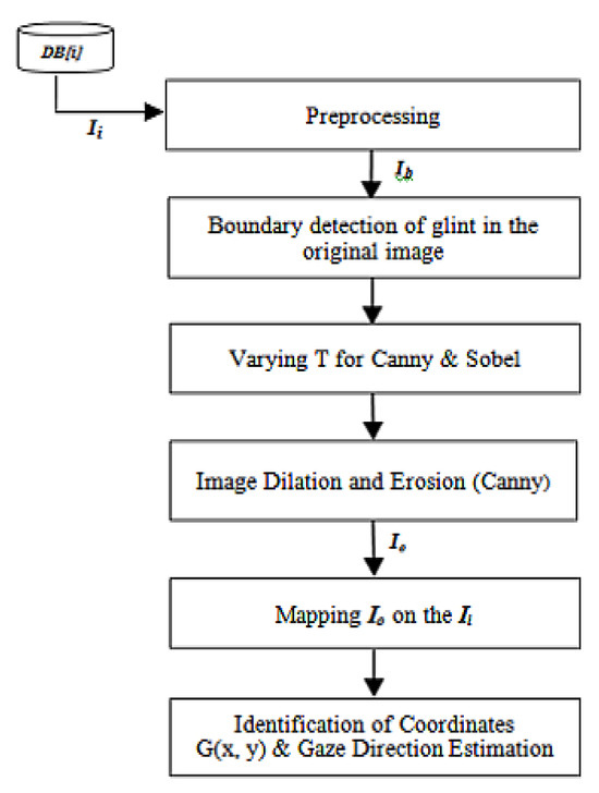
Figure 1.
Workflow of proposed GDE algorithm.
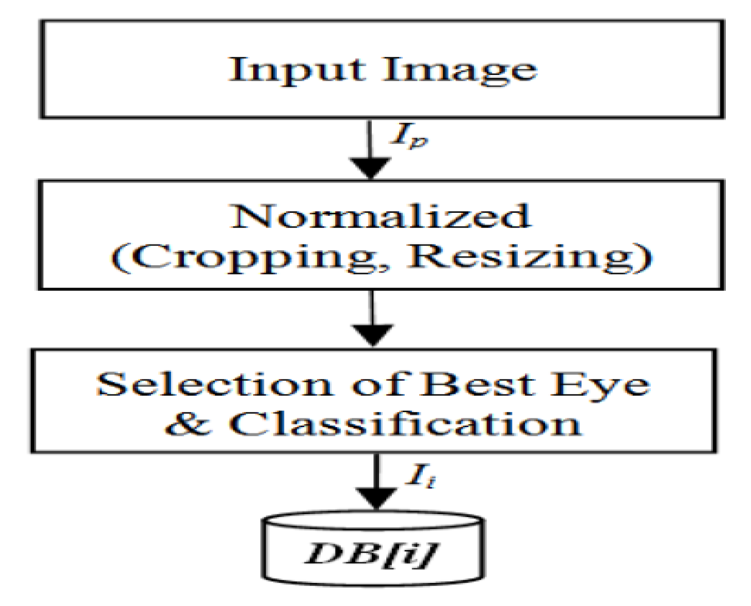
An input image, Ii is taken for the generation of binary image Ib.
The generation of Ib is based on the threshold value T obtained using two standard detectors canny and sobel. Each image is normalized to uniform size of 2500x1500 pixels in bmp format. This image Ii is further manually cropped and resized to 120 x 120 pixels for one best eye for the uniformity of results. The factors for the best eye selection include noise presence, relative clarity, pupil and glint visibility, formation of least number and brightness of glints, and presence of comparatively sharp edges.
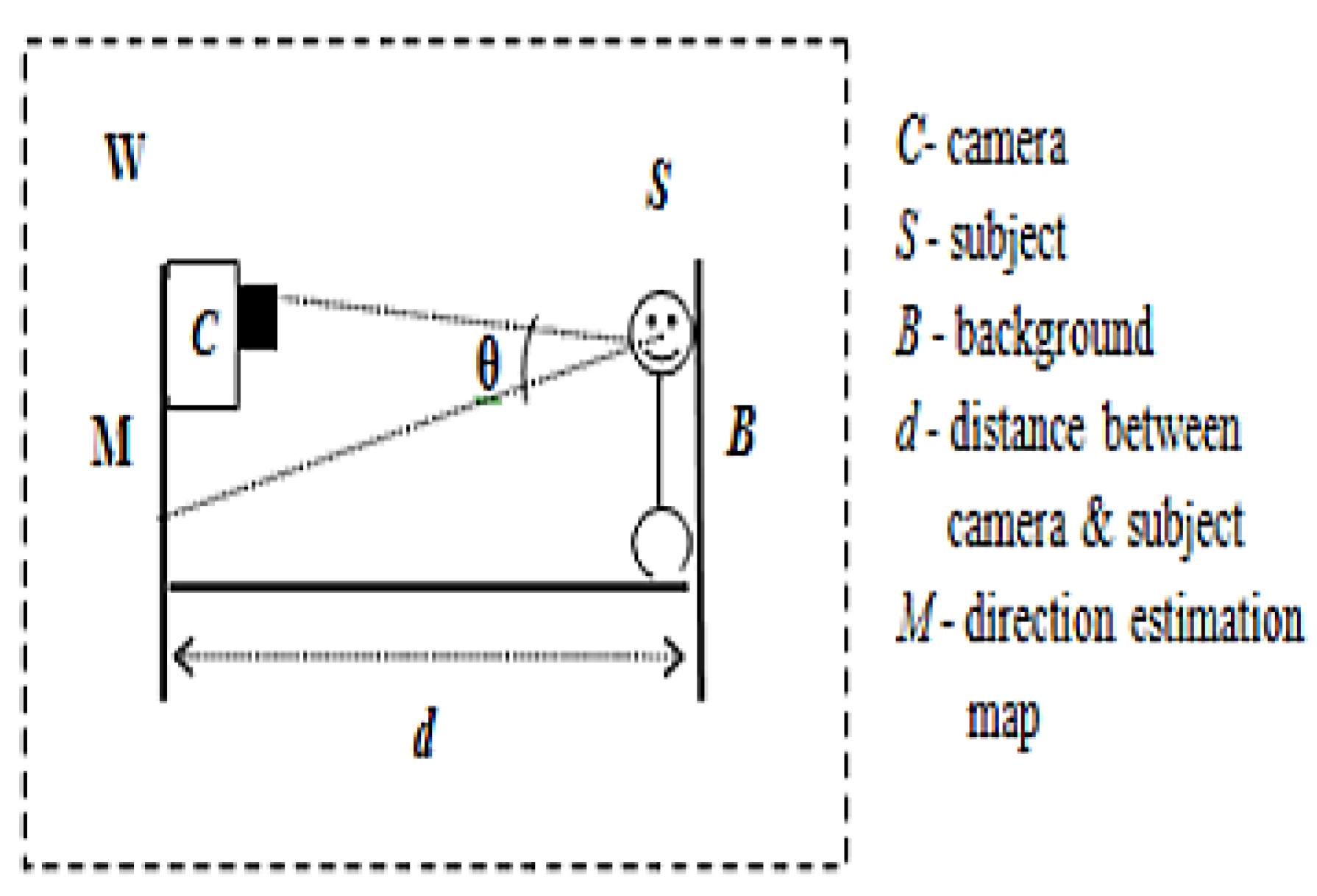
For experimental evaluation of GDE, a workspace W has been designed as shown in Figure 2. The W consists of the subject S placed at a constant distance d (4 feet) from the quadrant map M. Background B has been taken as plain white board for entire dataset so as to maintain uniformity of the input datasets and exclude any aberrations.
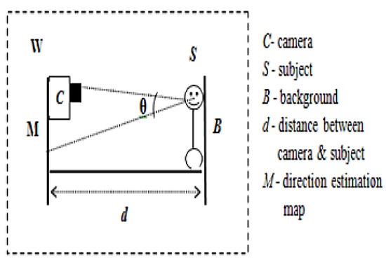
Figure 2.
Experimental setup for analysis of GDE model.
The data related to the position of the eye is acquired using an image capturing device C mounted on the map M facing S making an angle θ with normal. For current study, C is a digital camera of SONY NEX-5 ultra compact with resolution 4592x3056, 14.2 megapixels sensor and a large articulated 7.5 cm monitor for capturing high resolution images. The subjects are instructed to look into the five quadrants on the screen in a direction starting from C->TL->TR->BL->BR. Care has been taken to obtain the images of every subject with still head facing straight at the center of M. The illumination of the workspace W has also been kept uniform with one light source throughout for all the image datasets. Variation in the light conditions may affect the glint position or may produce multiple glints in the image thereby affecting the glint detection process.
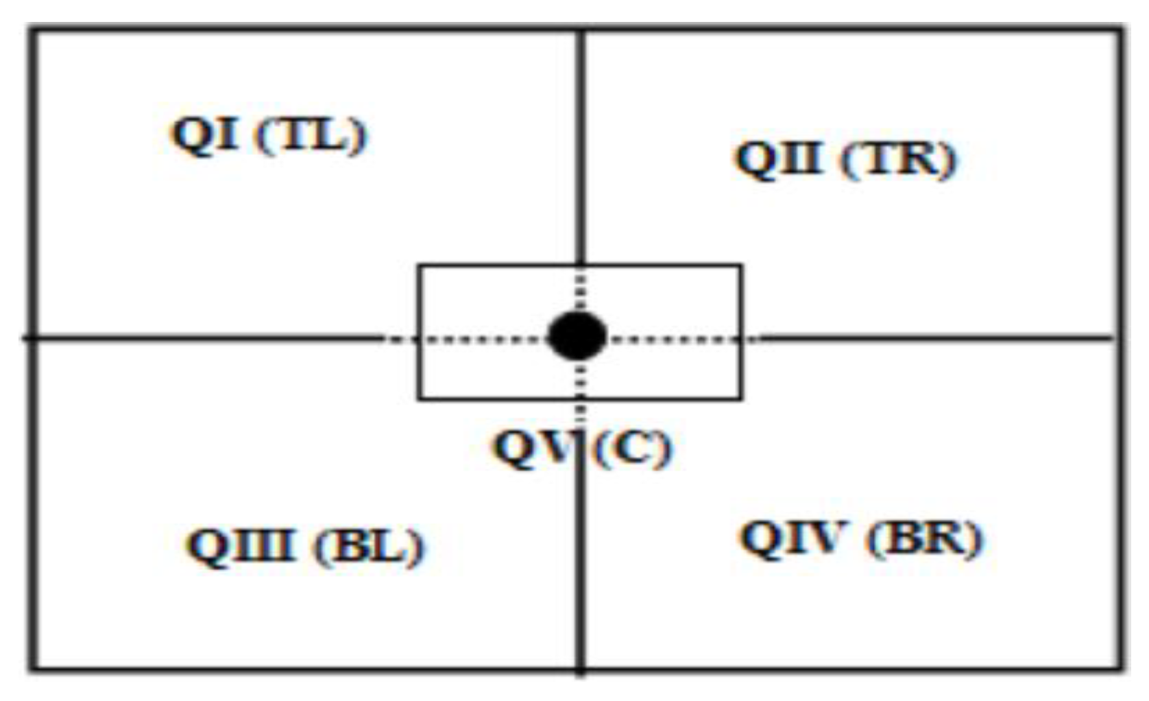
In order to make the results uniform and comparable, all the experiments have been conducted under the same lighting conditions. The gaze estimation map M has been designed (Figure 3) to analyse the accuracy of the gaze coordinates by GDE algorithm. For convenience and uniformity of the results, initially M is divided into five direction quadrants namely QI–TopLeft (TL) direction, QII– TopRight (TR), QIII–BottomLeft (BL), QIV– BottomRight (BR) and QV-Center (C). For example, if the subject is looking towards the Top right (TR) of the screen, the corresponding eye image is tagged as top right (TR) in the image dataset. The flowchart for the creation of DB[i] is shown in the Figure 4. The resultant images have been analysed for finding the relation between glint and five quadrants with the two edge detectors as mentioned above for the gaze direction.
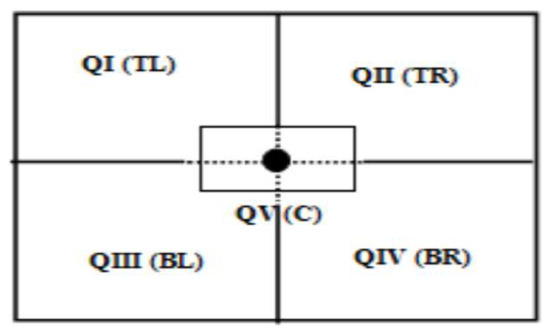
Figure 3.
Gaze estimation quadrants used for mapping M directions in GDE experimental setup.
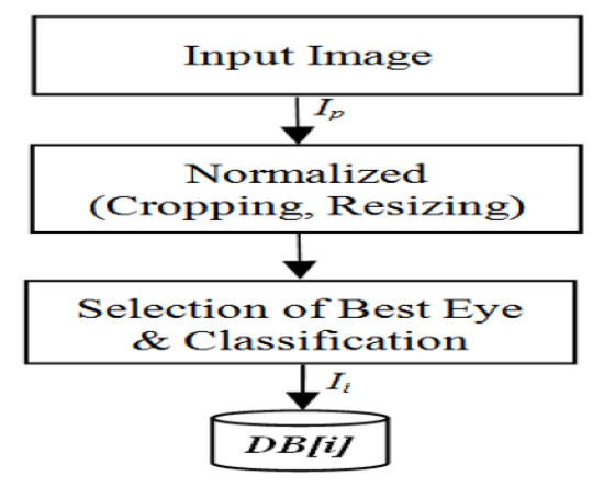
Figure 4.
Flowchart for creation of database DB[i] for experimental analysis of proposed GDE algorithm.
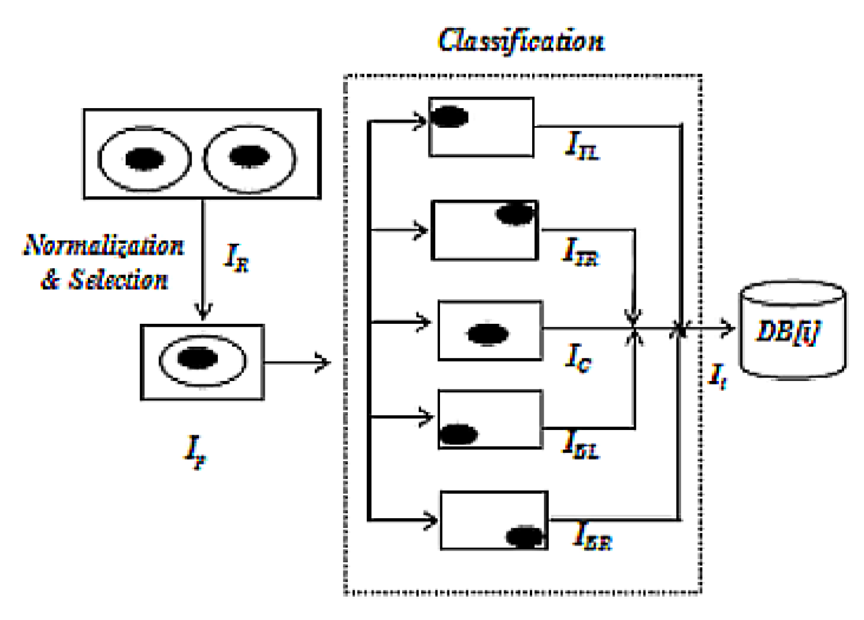
Each raw image Ir consists of two eye images of different subjects taken in real time using the digital cam era C specified above.
Ir is normalized by cropping only best eye and size adjustment for the required image area to generate Ip. Ip is classified to form Ii depending on the different quadrants as shown in Figure 5. Ii is then converted to gray scale and further to binary image for the smooth working of two edge detectors viz. canny and sobel.
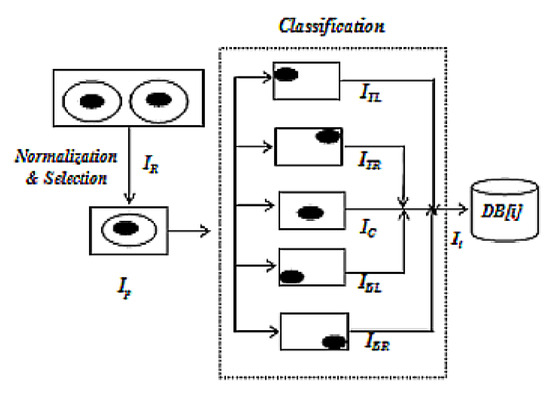
Figure 5.
Selection of one eye image Ip and manual classification in five defined quadrants for creating DB[i].
In this GDE model both the detectors are using two thresholds in a sequence for obtaining required binary image. In case of sobel detector, a threshold value T along with alpha factor α is applied to the sobel detector for detecting RoI. Factor α is adjusted and multiplied with T to form a set S as per the required edge pixels within a range of 1.467–5.800. Factor α is uniformly varied and the outputs generated are observed to find out the desired RoI. In some cases, the results obtained are not very significant, then the range of α is further increased if required. Further, different values of S have been given to sobel edge detectors for generating the required RoI. Edges are equated against the obtained thresholds for further detection of RoI i.e., glint in this study. Further the binary image is processed with different morphological image processing functions like erosion, dilation etc. for removing unwanted regions or boundaries for the location of exact glint coordinates. The canny detector generates the required glint region in the output images and also detects true weak edges and helps to fill in gaps in the detected edges.
In order to understand and analyse the working of the GDE model different cases of detection have been categorized after analysis of the output images. On the basis of detection of glint and subsequent gaze by GDE algorithm each output is classified into different categories. If both glint and subsequently gaze direction quadrant are estimated correctly, the output is marked as Correct Glint and Correct Gaze detection (CGlCGa). Similarly, the output is marked as Wrong glint and Wrong gaze (WGlWGa), in case GDE fails or detects wrong glint and correspondingly results in incorrect or inappropriate gaze. If GDE estimates any one of the glint or gaze correctly the output is marked as Correct Glint and Wrong Gaze (CGlWGa) or Wrong glint and Correct Gaze (WGlCGa). However if no glint is identified in Ii, the output is marked as No Glint (NGl).
An interface has been developed for the experimental evaluation of the proposed GDE algorithm in MATLAB R2013a environment using a Dell Optiplex990 model with Windows7 professional 64-bit Operating system, Intel ® core i5-2500 CPU, 3.10 GHz and 2 GB RAM.
The Picasa version 3.9.137 Photo Viewer is also used for editing images as per the requirement and processing of the resultant images.
Results and Discussion
As explained above, in this experimental study GDE model has been used to detect the RoI, i.e., glint in the input image of different eye images. It has been comparatively analysed using two standard edge detectors. The algorithm estimates the appropriate quadrant as tagged while classifying the Ii for DB[i] depending on the position of glint in Ii. A total number of Ii for each quadrant is 20. The generated output image Io is used further for the detection of glint coordinates g (x, y) and the gaze direction quadrant (TR) as shown in Figure 6. Execution of the feature based edge detection GDE algorithm on the image generates the gaze direction and the glint coordinates after mapping.
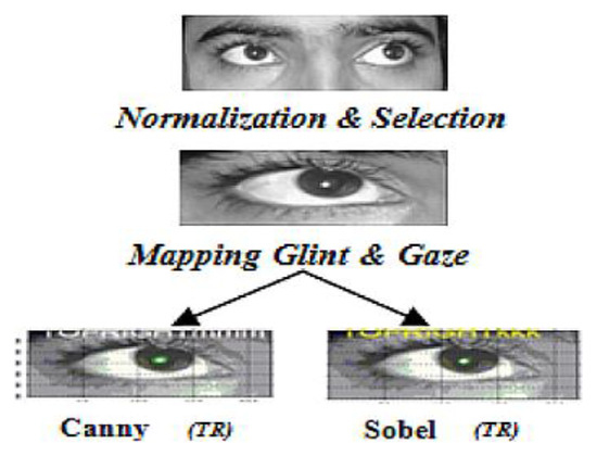
Figure 6.
Estimating gaze direction.
The processed image is obtained after all the morphological operations explained above accurately separates out the glint from rest of the image, for twenty different subjects using the GDE algorithm for glint and quadrant detection using both detectors.
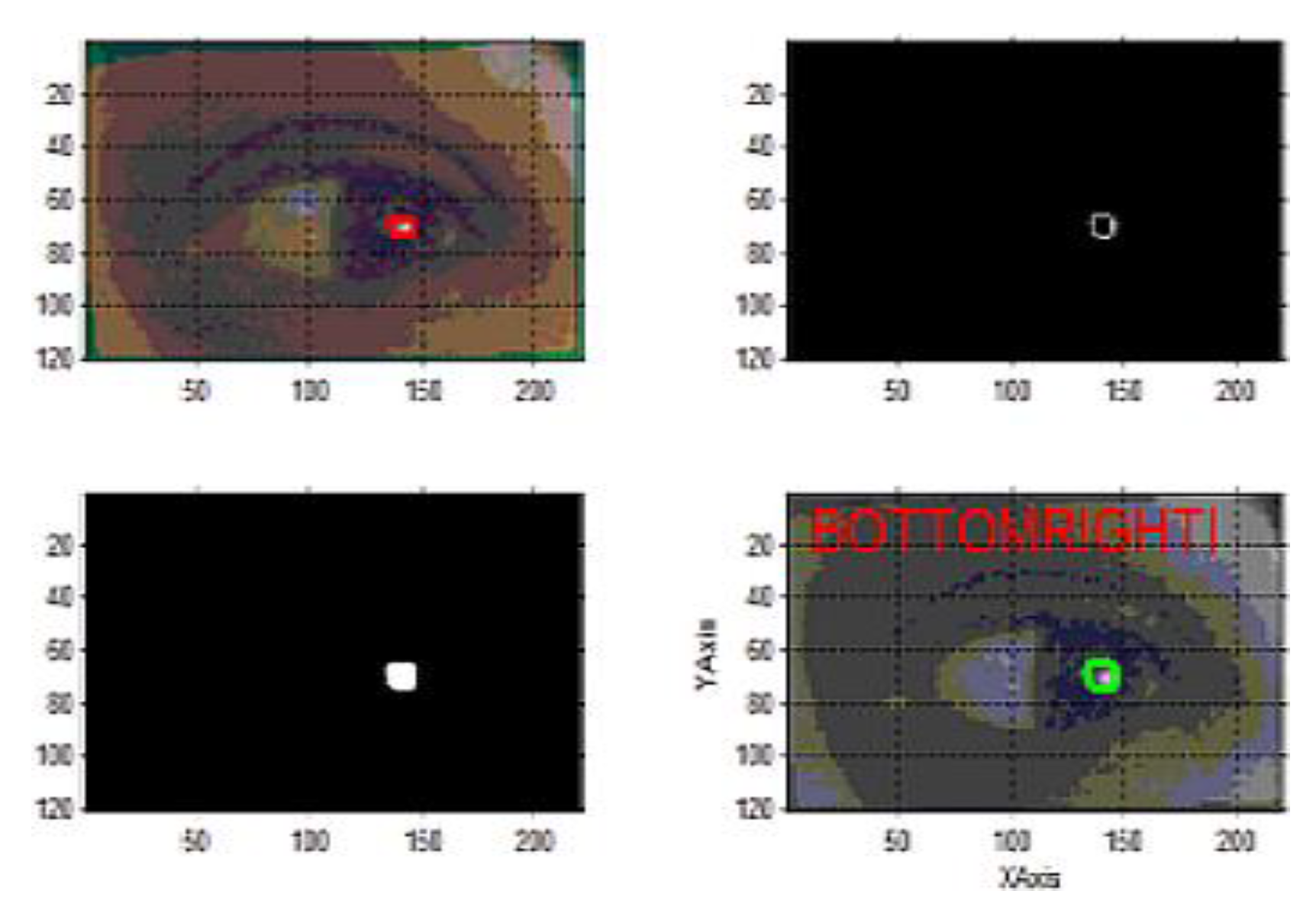
Finally the coordinates of glint and appropriate quadrants are obtained after removing the extra edges, dots etc. if visible. Figure 7(a) shows the input image Ii and the binary image Ib (Figure 7(b)) generated after applying proper thresholds and other morphological operations respectively. Extra objects are filtered out using morphological operators as explained above in the edge detectors to obtain the correct glint and gaze (CGlCGa) (Figure 7(c)) which is finally superimposed on Ii to obtain final RoI. The result of superimposition of Io on the Ii is shown in Figure 7(d). The best eye and its corresponding gaze quadrant from the input image Io is taken for processing.

Figure 7.
Superimposing Io on Ii for mapping glint & gaze (a-d).
Further results are generated for the output images Io by the GDE algorithm with the detected quadrant. Finally estimation of the gaze direction is done.
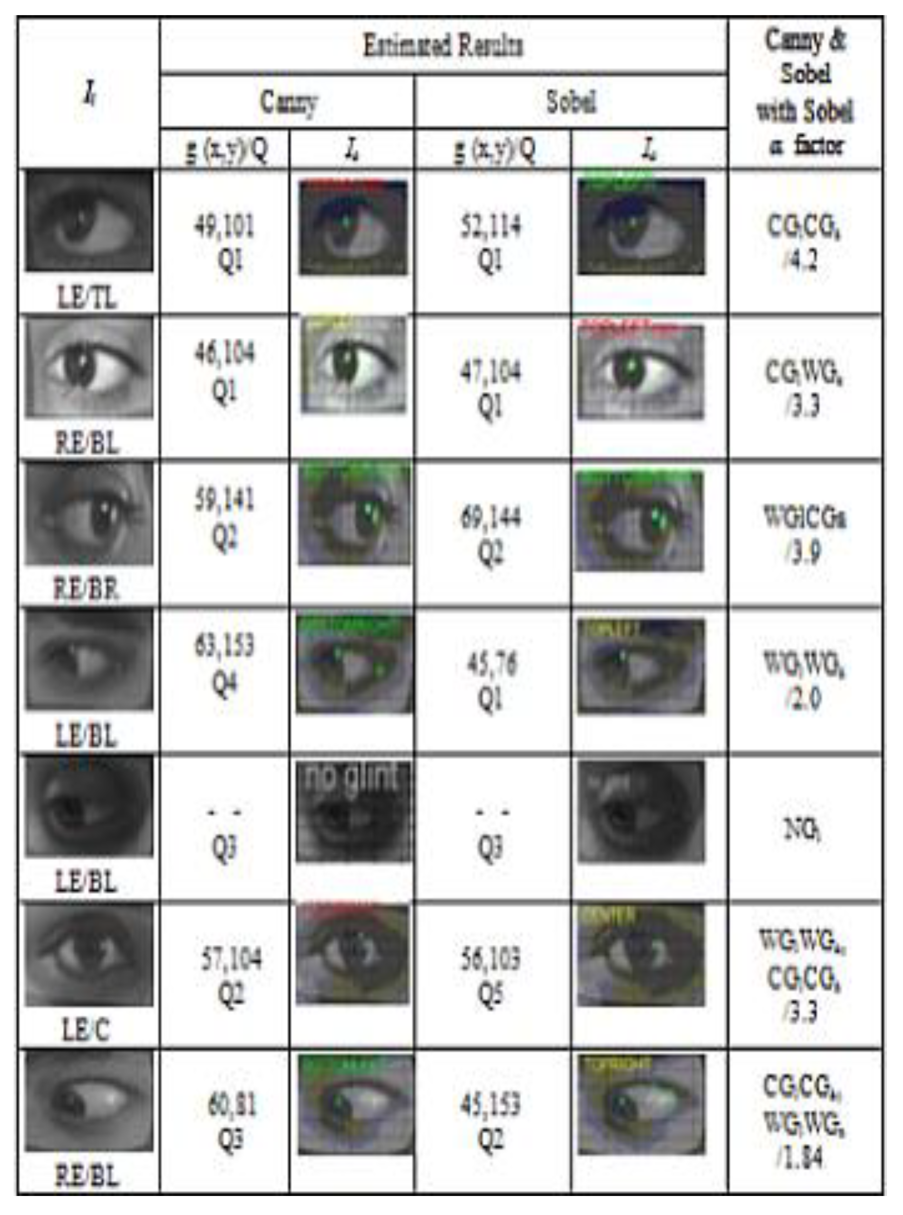
Different inputs each classified as left eye (LE) or right eye (RE) along with the actual quadrant and the corresponding glint coordinates and gaze direction estimated by GDE are presented in Table 1.

Table 1.
Analysis of different one eye input images for the glint coordinates and direction quadrants iden-tified by the proposed GDE algorithm.
The detected g (x, y) coordinates along with the quadrant Qi of each image has been shown in front of each input image. The column Io depicts the corresponding processed output image. The last column of the table shows the classification of resultant detected gaze. For example, in the first case both canny and sobel detect CGlCGa with sobel α factor 4.2 given as (CGlCGa/4.2) in the Table 1. However, the fifth input of the table indicates that no glint has been detected either by canny and sobel.
Similarly, canny generates wrong glint and correspondingly wrong gaze (WGlWGa) whereas sobel detects the glint and gaze correctly (CGlCGa) in the sixth image. Similar results were generated and analysed for other input images also. Further the glint in some images is correctly detected by canny and needed certain modification in the above parameters for the sobel detector.
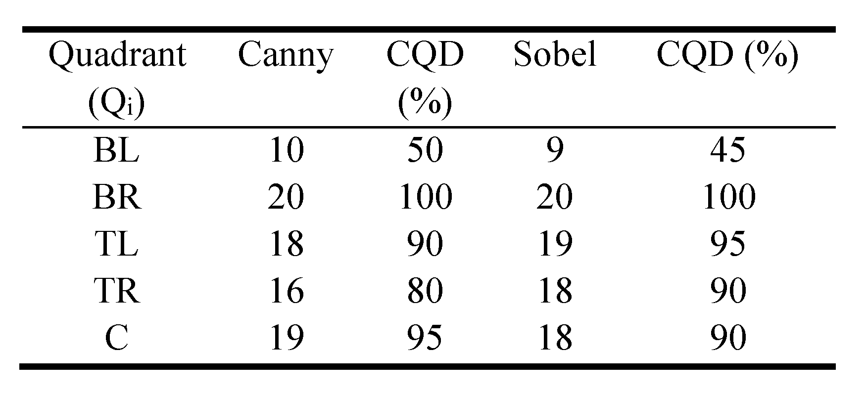
However, in some cases preprocessing is required for the values of control parameters viz. threshold T and α. The input images with improper glint along with the other parameters may affect the results. The canny’s success rate is 82% whereas it is 80% for the sobel detector. Factor α is also analysed for its importance in the threshold of the sobel detector. The most prominent value of α range is within 2.8 and 3.5 which are giving correct glint detection for 10 images each with the threshold. Further, for the value of α lesser than 2.8, 31% images were producing the correct glint. Nineteen percent of the result is for the values of α which are greater than 2.8 and less than 3.5. The factor α for other images is greater than 3.4 and less than 5.8. Table 2 shows the percentage of correct quadrant detection. Five input images for each quadrant are taken for 20 different subjects. Both canny and sobel generate fairly good results.
Table 2.
Results of quadrant detection for both canny & sobel.
Almost one hundred percent detection is obtained for the BR quadrant for both the detectors with a lesser percentage for the TL quadrant of sobel and the C quadrant of canny. More than 90% detection is achieved in case of gaze direction TL of canny detector and TR and C quadrants of the sobel edge detector. Eighty percent CQD rate is for the TR quadrant of canny. The BL quadrant detection is considerably less by both the detectors. Only 50 and 45 detection in percent is achieved.
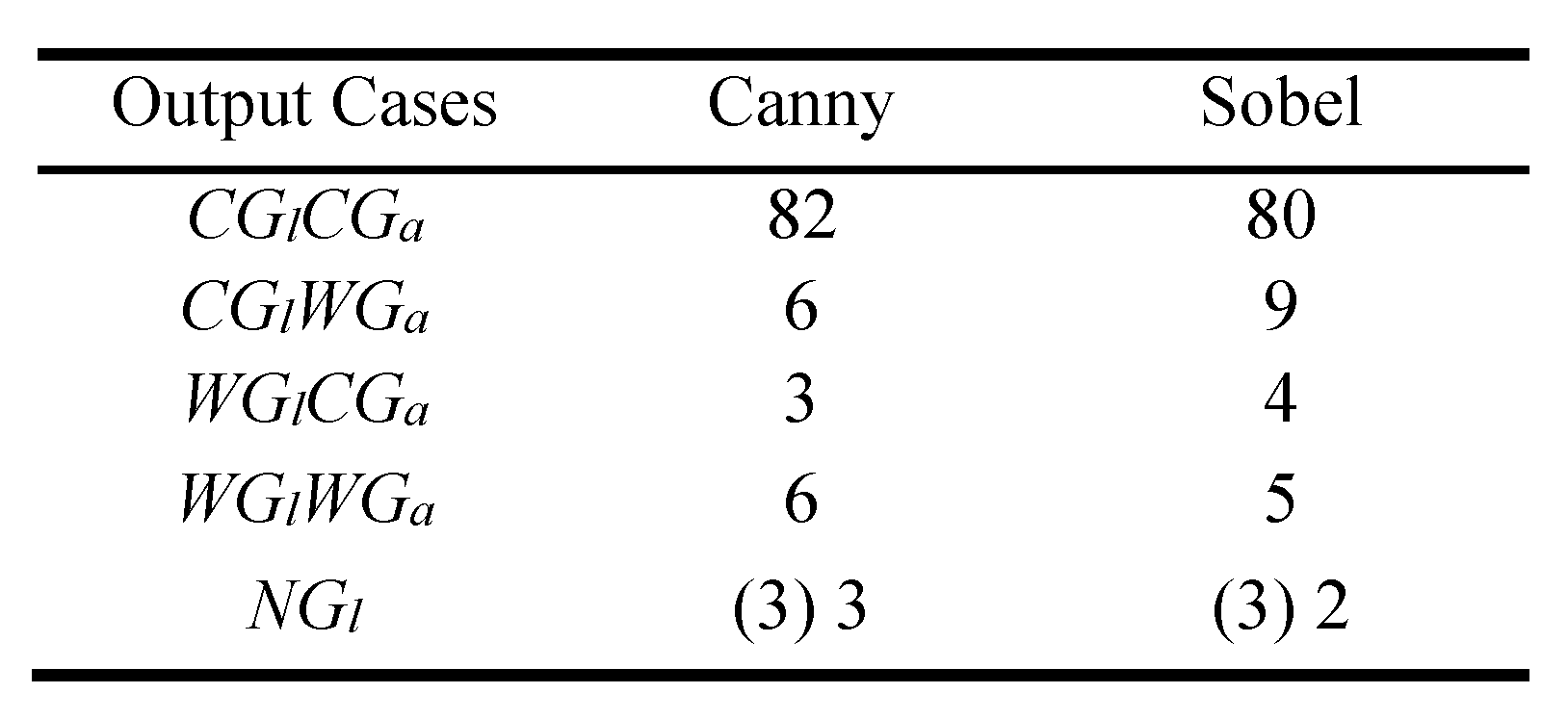
Failure of edge detectors in this BL quadrant in finding the CQD may be due to partial or unintentional blinking or occlusion of eye or eyelids resulting in poor or inappropriate formation of glint. Further, the output images are categorized and analysed for different results as shown in Table 3.
Table 3.
Similar output cases of glint and gaze detection (%).
The five output cases have been identified. A total of 162 output images have been generated by both the detectors for hundred images each for sobel and canny. The number of images detected correctly for glint as well as for the gaze direction (CGlCGa) is 82 for canny and 80 for sobel.
In CGlWGa, a total of six and nine images for canny and sobel respectively have been correctly detected. Out of seven output images generated under WGlCGa, there are three images detected correctly using canny and rest by sobel detector respectively. While the edge detectors are detecting a good number of images with correct glint and gaze, in case of failures, the edge detectors may be finding glint coordinates that may not appropriately mapping quadrant map, M.
This leads to incorrect gaze estimation due to the variety of reasons like multiple glints, incorrect position of the glint formation, hazy or blur glint intensity or absence of proper glint as shown in Table 3.
Figure 8 represents all the above mentioned cases. 162 output images have detected CGlCGa. In WGlWGa case, out of a total of eleven output images, correct detection for canny is six. In this case, the proposed GDE algorithm fails to detect either correct glint or correct gaze quadrant in some of the input images. The last case NGl pertains to no glint detection. This failure may be due to certain factors like absence of glint, occlusion of eye and position of light source, etc. In this experimental analysis, the GDE algorithm is unable to detect the glint (NGl) for three images where there is no formation of glint in the corresponding input image (Table 3).
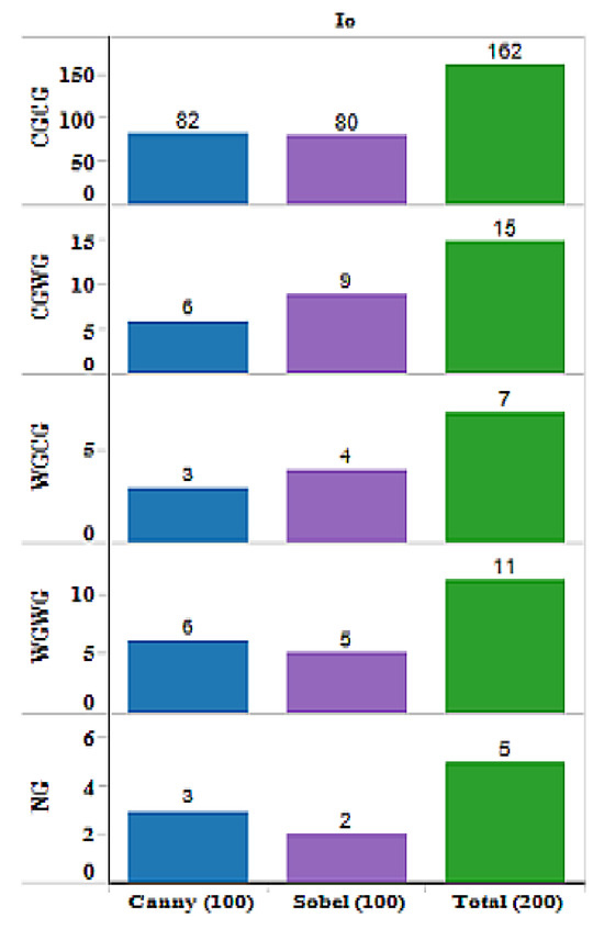
Figure 8.
Comparative analysis of canny and sobel edge detectors using proposed GDE algorithm on the basis of glint coordinates and gaze direction estimate of different input images.
Out of the three images of NGl, the canny detector has given 100% correct detection. Sobel has detected only two NGl images including one with no glint but correct gaze detection. The unsuccessful result is for a total of five images in which no glint is visible. This mainly pertains to BL quadrant and may be due to the light or occlusion factors etc.
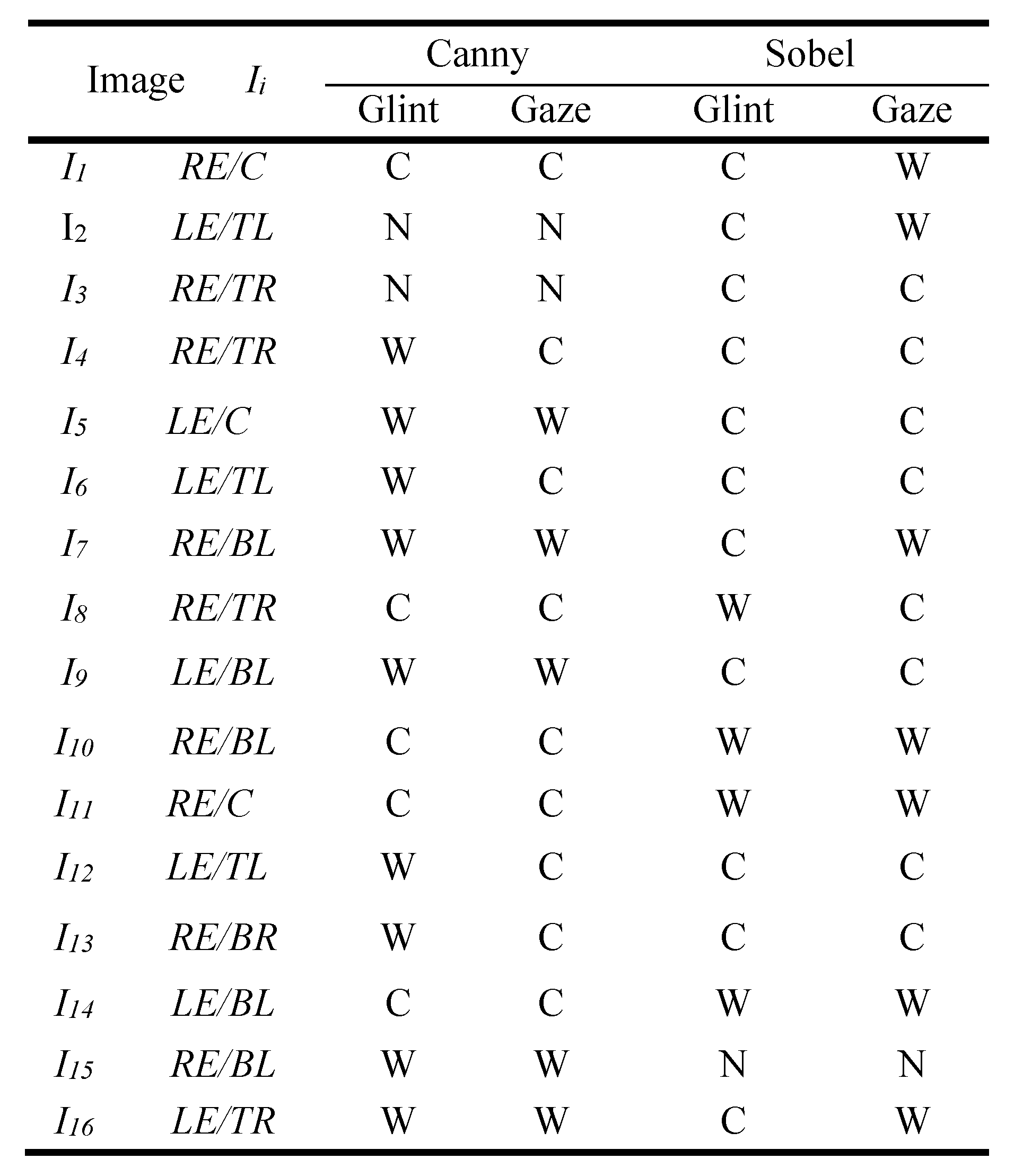
Table 4 depicts the performance of canny and sobel detectors as evaluated by the GDE algorithm. Images with corresponding selected eye (RE/LE) along with the original direction quadrants are shown in first two columns of the Table 4.
Table 4.
Performance evaluation of the canny and sobel detectors by the proposed GDE algorithm.
The subsequent columns contain the generated different cases of glint and gaze detection by the edge detectors, canny and sobel. Out of 100 test images, sixteen with dissimilar outputs have been presented in the Table 4.
However in four cases (I4, I6, I12 and I13) where the glint is wrongly detected, the gaze is appropriately detected using canny operator. The sobel detector accurately detects four glints but with wrong quadrants. In some cases canny detector finds no glint and gaze but sobel detects correct glint in one image (I2) and both CGlCGa in another image (I2 and I3). Similarly there are instances where canny neither detects glint nor gaze. However, in these cases sobel is able to find the CGlCGa completely (I5 and I9). The same is vice versa true in case of sobel for I10, I11 and I14. There are cases where only CGl is detected by one detector but using other detector generated correct result for both glint and gaze.
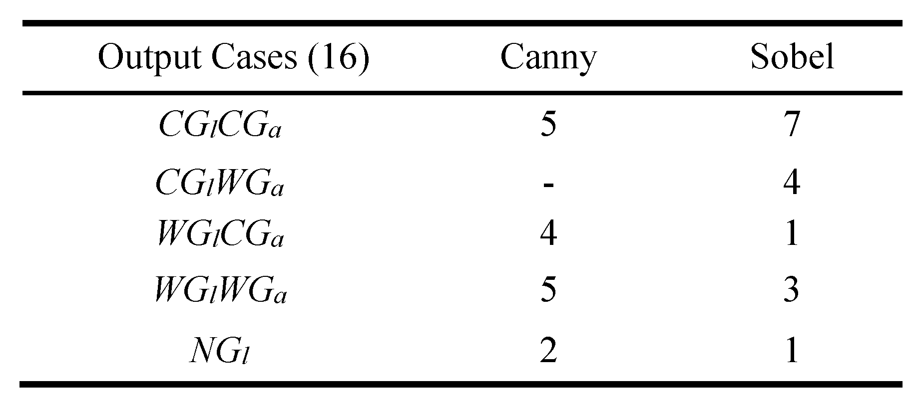
The study suggests that more than one detector may be suitable for the accuracy of the proposed algorithm. The total number of output cases as detected by the GDE algorithm has been shown in Table 5.
Table 5.
Comparison of edge detectors for dissimilar outputs.
For CGlCGa, seven cases using sobel and five cases using canny operator have been obtained. No case of wrong gaze with correct glint has been detected using canny. However, four such cases have been detected for sobel. Two cases of NGl for canny detector and one case of NGl for sobel have been detected by the GDE algorithm respectively.
The analysis of the results obtained by the proposed GDE model shows the detection of glint coordinates and further gaze direction for the input images. It has also been observed that the accuracy of glint detection in eye gaze based system depends on several factors like formation of proper glint and control parameters. Further, it has been observed that more than one edge detector can be effectively used for the detection of glint in eye gaze models. Standard detectors like canny and sobel produce reasonable results. However canny edge detection generates more accurate results than sobel.
It has been further observed that canny detector detects correct glint and correct gaze in 82 images whereas sobel detects 80 correct glint and gaze in the images. In rest of the cases either incorrect gaze or glint or both have been detected. It is important to understand that in the rest of these cases the edge detectors may be generating the glint coordinates that may not be corresponding to the appropriate quadrant map M leading to incorrect gaze estimation. This may be due to a number of reasons like multiple glints, incorrect position of the glint formation, hazy or blur glint intensity or absence of proper glint.
Conclusions
In this research paper Gaze Direction Estimation (GDE) model has been proposed for the detection of glint coordinates and gaze quadrant of the input eye image using edge detection operators. The model has been tested by creating an image database using hundred images taken from twenty different subjects for five different quadrants in the experimental setup. The input images are processed for uniformity. The output glint coordinates and estimated gaze direction of the user is compared with the actual user gaze to test the efficiency and accuracy of the model. For this study, two standard edge detectors canny and sobel have been used. Varying values of threshold T and α factor value along with other parameters are used to obtain suitable results. The gaze has been estimated using a map which for this study has been divided into five quadrants.
The result shows 81% success rate in which the system was able to detect correct glint and subsequently correct gaze. The other remaining images, however, detect either the correct gaze or the glint correct but not both. Some images detect correct glint with appropriate quadrant for both the detectors. In 7.5% of the total images correct glint coordinates were detected, however the gaze could not be detected correctly by both the detectors. Only 3.5%, of the output images detected the gaze quadrants correctly even when the glint coordinates are not detected correctly. This may be attributed to multiple or improper glint formation, presence of unwanted sharp, bright dots or extra edges around the glint. However 5.5% of the input images in the algorithm fail to detect either correct glint or correct gaze quadrant. Only 2.5% of the images show no glint detection. The factors responsible for the no glint case in the image can be the light source, blinking or occlusion of eyelid and wrong or multiple glint formation. In some cases, parameters are required to be varied for glint detection. However, in general the performance of the canny detector is marginally better than that of the sobel detector. The proposed algorithm detects glint and better estimates the gaze direction. Based on the study it can be concluded that the detection of glint coordinates and gaze direction in eye gaze models can be effectively done with more than one edge detector with the help of proposed GDE model. The main features of this method include cost effectiveness, use of ubiquitous hardware and software and simplified image capturing procedure.
The outcome of this experimental study may be helpful for designing simpler, low cost and nonintrusive devices for gaze based control systems for various applications like hands free control and operation of the computing systems especially for physically disabled persons, gaze based page control for orchestra, gaze assisted support devices for surgeons, and gaze based system authentications.
However, there are certain limitations of the proposed model. The proposed algorithm finds it difficult to determine the exact glint boundaries due to involvement of sclera in the glint formation in some cases. This prevents the algorithm from determining the accurate corneal reflection, i.e., the glint in some cases.The limitation of head movement restriction can be overcome by using a wideangle face camera and a pan-tilt controlled eye camera which may add the extra cost and complexity to the model. Manual cropping and parametric values including threshold and α factor for large domain of input images need further analysis for uniformity. The map used for gaze estimation may further be divided into more number of quadrants for better precision. Other factors include high dependency of glint formation on orientation, position and number of the light sources. The algorithm may further be modified to reduce the initial processing and to further automate the process for better and more accurate results.
References
- Bates, R., H. Istance, L. Oosthuizen, and P. Majaranta. 2005. Survey of De-Facto standards in eye tracking. Communication by Gaze Interaction (COGAIN), IST-2003-511598. Available online: http://www.cogain.org/reports.
- Bednarik, R., T. Gowases, and M. Tukiainen. 2009. Gaze interaction enhances problem solving: Effects of dwell-time based, gaze-augmented and mouse interaction on problem-solving strategies and user experience. Journal of Eye Movement Research 3, 1: 1–10. [Google Scholar]
- Bialkowski, S., Z. Jonhson, K. Morgan, X. Qi, and D. Cooley. 2007. A non-intrusive approach to gaze estimation. Available online: http://digital.cs.usu.edu/~xqi/Tenure/JCIS.GazeEstimation.07.pdf.
- Blignaut, P. J. 2013. Mapping the pupil-glint vector to gaze coordinates in a simple video based eye tracker. Journal of Eye Movement Research 7, 1: 1–11. [Google Scholar] [CrossRef]
- Choo, C., J. W. Lee, K.Y. Shin, E. C. Lee, K. R. Park, H. Lee, and J. Cha. 2012. Gaze detection by wearable eye-tracking and NIR LED-based head-tracking device based on SVR. ETRI Journal 34, 4: 542–552. [Google Scholar] [CrossRef]
- Djeraba, C. 2010. Estimation of visual gaze: in multimodal user interactions in controlled environments. Springer Science+Business Media chap. 4: 99–141. [Google Scholar]
- Ebisawa, Y. 1998. Improved video-based eye-gaze detection method. IEEE Transaction, Instrumentation and Measurement 47, 4: 948–955. [Google Scholar] [CrossRef]
- Erdogmus, N., and J. L. Dugelay. 2010. An efficient iris and eye corners extraction method. Proceedings of Joint IAPR International Workshop, SSPR & SPR 6218: 549–558. [Google Scholar]
- Feng, G. C., and P. C. Yuen. 1998. Variance projection function and its application to eye detection for human face recognition. In Pattern Recognition. Elsevier: pp. 899–906. [Google Scholar]
- Goni, S., J. Echeto, A. Villanueva, and R. Cabeza. 2004. Robust algorithm for pupil-glint vector detection in a video-oculography eyetracking system. In Proceedings of the 17th International Conference on Pattern Recognition, IEEEXplore 4. pp. 1–4. [Google Scholar]
- Guestrin, E. D., and M. Eizenman. 2006. General theory of remote gaze estimation using the pupil center and corneal reflections. IEEE Transaction Biomedical Eng. 53, 6: 1124–1133. [Google Scholar] [CrossRef]
- Hansen, D. W., and Q. Ji. 2010. In the eye of the beholder: A survey of models for eyes and gaze. IEEE Transactions on Pattern Analysis and Machine Intelligence 32, 3: 478–500. [Google Scholar] [CrossRef] [PubMed]
- Jacob, R. J. K. 1991. The use of eye movements in human computer interaction techniques: What you look at is what you get. ACM Transactions on Information System 9, 2: 152–169. [Google Scholar]
- Kim, K. N., and R.S. Ramakrishna. 1999. Vision-based eye-gaze tracking for human computer interface. In Proceedings of IEEE Systems, Man and Cybernetics Conference, 2. pp. 324–329. [Google Scholar]
- Lee, T. H. 2012. Edge detection analysis. International Journal of Computer Science Issues 5, 6: 1–25. [Google Scholar]
- Lewis, J. R., and et al. 2013. Gaze detection in a see-through, near-eye, mixed reality display, Special applications human body observation eye. US Patent 20130286178, Oct. 31 [Online]. Available online: http://www.faqs.org/patents/app/20130286178#ixzz3HcHbqTgf.
- Maini, R., and H. Aggarwal. 2009. Study and comparison of various image edge detection techniques. International Journal of Image Processing (IJIP) 3, 1: 1–12. [Google Scholar]
- Mollenbach, E., J. P. Hansen, and M. Lillholm. 2013. Eye movements in gaze interaction. Journal of Eye Movement Research 6, 2: 1–15. [Google Scholar] [CrossRef]
- Nagaraju, C., S. Nagamani, G. Rakesh Prasad, and S. Sunitha. 2011. Morphological edge detection algorithm based on multi-structure elements of different directions. International Journal of Information and Communication Technology Research 1, 1: 37–43. [Google Scholar]
- Nakazawa, A., and C. Nitschke. 2012. Point of gaze estimation through corneal surface reflection in an active illumination environment. Proceedings of European Conference on Computer Vision SpringerVerlag; pp. 159–172. [Google Scholar]
- Ohno, T., N. Mukawa, and A. Yoshikawa. 2002. Freegaze: A gaze tracking system for everyday gaze interaction. Proceedings of Eye Tracking Research & Application (ETRA); pp. 125–132. [Google Scholar]
- Ohtani, M., and Y. Ebisawa. 1995. Eye gaze detection based on the pupil detection technique using two light sources and the image difference method. IEEEEMBC and CMBEC, Theme 7: Instrumentation (1623-, 1623: 1623–1624. [Google Scholar]
- Patil, A., and M. Dhanvijay. 2015. Blob detection technique using image processing for identification of machine printed characters. International Journal of Innovations in Engineering Research and Technology (IJIERT) 2, 10: 1–8. [Google Scholar]
- Perez, A., M. L. Cordoba, A. Garcia, R. Mendez, M. L. Munoz, J. L. Pedraza, and F. A. Sanchez. 2003. Precise eye gaze detection and tracking system. In Proceedings of 11th International Conference in Central Europe on Computer Graphics, Visualization and Computer Vision. pp. 105–108. [Google Scholar]
- Petkovsek, S., K. Huang, and B. Poudel. 2012. Gaze controlled human-computer interface. In Senior Theses and Projects Student Works. Trinity College Digital Repository. [Google Scholar]
- Rakesh, R. R., P. Chaudhuri, and C. A. Murthy. 2004. Thresholding in edge detection: A statistical approach. IEEE Transactions on Image Processing 13, 7: 927936. [Google Scholar] [CrossRef] [PubMed]
- Sharma, A., and P. Abrol. 2013. Eye gaze techniques for human computer interaction: A Research Survey. International Journal of Computer Applications (IJCA) 71, 9: 18–29. [Google Scholar]
- Sharma, A., and P. Abrol. 2015a. Evaluating interactivity with respect to distance and orientation variables of GDE model. Proceedings of the Springer International Congress on Information and Communication Technology (Advances in Intelligent Systems and Computing), 438, Singapore; pp. 177–187. [Google Scholar] [CrossRef]
- Sharma, A., and P. Abrol. 2015b. Glint detection and evaluation using edge detectors. International Journal of Scientific and Technical Advancements 1, 3: 319–323. [Google Scholar]
- Sharma, A., and P. Abrol. 2015c. Comparative analysis of edge detection operators for better glint detection. In Proceedings of 9th INDIACOM 2nd International Conference on Computing for Sustainable Global Development. IEEExplore digital library: pp. 973–977. ISBN 978-9-3805-4415-1. [Google Scholar]
- Sharma, D., and P. Abrol. 2012. SVD based noise removal technique: An experimental analysis. International Journal of Advanced Research in Computer Science 3, 5: 214–218. [Google Scholar]
- Sibert, L., and R. J. K. Jacob. 2000. Evaluation of eye gaze interaction. In Proceedings of SIGCHI conference on Human factors in Computing System, ACM. pp. 281–288. [Google Scholar]
- Song, J., Z. Chi, Z. Wang, and W. Wang. 2005. Locating human eyes using edge and intensity information. In ICIC 2005, Part II, LNCS 3645. Springer Verlag Berlin Heidelberg: pp. 492–501. [Google Scholar]
- Sookman, S. 2006. Blob Analysis and edge detection in the real world. Available online: http://www.evaluationengineering.com/articles/200608/blob-analysis-and-edge-detection-in-the-real-world.php.
- Wang, J. G., E. Sung, and R. Venkateswarlua. 2005. Estimating the eye gaze from one eye. In Computer Vision and Image Understanding 98. Elsevier: pp. 83–103. [Google Scholar]
- Zhang, P., W. Zhiliang, S. Zheng, and X. Gu. 2009. A design and research of eye gaze tracking system based on stereovision. In Lecture Notes in Computer Science, Emerging Intelligent Computing Technology and Applications. Springer-Verlag Berlin Heidelberg: vol. 5754, pp. 278–286. [Google Scholar]
- Zhu, Z., and Q. Ji. 2004. Eye and gaze tracking for interactive graphic display. Machine Vision Applications, Springer 15, 3: 139–148. [Google Scholar]
- Zhu, Z., and Q. Ji. 2007. Novel eye gaze tracking techniques under natural head movement. IEEE Transactions on Biomedical Engineering 54, 12: 2246–2260. [Google Scholar] [CrossRef] [PubMed]

Copyright © 2016. This article is licensed under a Creative Commons Attribution 4.0 International License.