


Abstract
The “Maestro Arm,” presented in this paper, is a modular wearable robotic arm with a five-fingered hand and wrist, elbow, and shoulder joints. The arm attaches to a waist belt to serve as a wearable third arm and can detach from its shoulder interface for mounting on external platforms such as a table or wheelchair. The dexterous, underactuated hand features a biomimetic joint design with 6 degrees of freedom and can output 18.4 N of grip force and 66.7 N of pulling force. A generatively designed forearm internal structure houses all necessary electronics. Cycloidal gear actuation systems control the arm’s vertical (shoulder joint) and horizontal (elbow joint) motions, providing 17 Nm and 8.5 Nm of lifting torque, respectively. The modular attachment architecture also provides a basis for future investigation of prosthetic configurations; however, this study does not cover socket design, residual-limb attachment, suspension, or clinical prosthetic use. The arm is fully controlled by an insole-based custom foot controller, called “Maestro Step.” This foot controller has two push buttons that control finger actuation and the grip pattern. The user’s ankle motion controls the shoulder, elbow, and wrist joints, with gesture recognition to switch between joints.
1. Introduction
Wearable robotic arms (WRA) and prostheses play a vital role in restoring mobility or augmenting human capabilities [1,2]. The global population of individuals with limited mobility continues to increase due to illness, trauma, conflict, and genetic conditions [3,4]. The World Health Organization (WHO) estimates that approximately 2 billion people will require assistive devices by 2050 [5]. Recent studies have also shown a steady rise in rotator cuff surgeries, reporting 314,239 repairs from 2007 to 2016 [6]. Similarly, the population of individuals living with limb loss in the United States is said to double by 2050, with rates predicted to increase by 145% by 2060 [4]. However, many commercially available upper-limb prosthetic systems are designed primarily for permanent limb loss, leaving few options for temporary injuries or users who would benefit from a wearable third arm. Proposed designs of supernumerary robotic limbs (SRLs) have shown promise for individuals with arm impairments [7]. Consequently, demand is growing for functional, lightweight, wearable robotic arms.
WRAs have proven to reduce human burden and improve work efficiency by restoring lost functions and enhancing human capabilities [8]. Because these devices can also aid in rehabilitation, a key factor to consider is the total system weight. If the system is too heavy, the WRA counteracts its direct purpose by adding additional burden on the user. The same applies to prosthetic devices, as the biggest reason for user rejection is weight [9]. Typically, as the system’s total number of degrees of freedom (DOF) increases, weight also increases because actuators are added at various joints [10]. For example, Parietti and Asada [11] WRA system that assists with tasks such as positioning a workpiece, operating a powered tool, or securing the human body, consists of a backpack-type mounting at the waist with 6 degrees of freedom and weighs 15 kg. Another WRA, designed by Parietti et al. [12] to provide two additional legs to augment stability and reduce loads on human leg joints, had 3 DOFs and weighed 9 kg. Véronneau et al. [13] proposed a hip-mounted WRA to assist with panel installation and painting, with 2 DOFs and a mass of 2.7 kg. Although a direct comparison of all WRA designs in the literature is difficult because each system was developed for specific tasks, Table A1 in Appendix A summarizes the configuration, number of DOFs, mass, user-control input, and reported applications of selected WRAs from the literature. Because the reported systems use different design objectives and evaluation protocols, the values should be interpreted as contextual information rather than as a direct performance ranking. Another factor to consider is collision safety and cooperativeness with the WRA user, which can be affected by factors such as the attachment position on the user and the length of the robotic arm [14]. Attachment position affects cognitive load and reachable workspace [15].
Control interfaces for wearable robotic limbs and upper-limb prostheses can be broadly categorized as biosignal-based, body-motion-based, inertial-based, external-environment-based, shared or semiautonomous, and hybrid interfaces, as shown in Table 1.
Table 1.
Control interfaces used for WRA and upper limb prostheses.
Biosignal interfaces include surface or intramuscular electromyography (iEMG or sEMG) and electroencephalography (EEG). iEMG involves integrating sensors directly inside the user’s body. Although the signals are read accurately, this method is highly invasive and may be undesirable and costly for many. In contrast, sEMG is less invasive because sensors are placed on the surface of the user’s skin [16]. However, sEMG can often result in muscle fatigue and face several signal issues arising from the user’s skin conditions [17]. These signals also support a limited number of commands, making control systems that manage multiple joints and gestures complicated. Furthermore, EMG control cannot be used for all amputees and injured individuals, as they require specific muscles to collect data. If the user is missing the specific muscle or cannot contract it due to limited mobility, EMG is no longer an option. If the user does happen to be eligible for EMG, it often leads to mental exhaustion for users [18]. These factors contribute to a high upper-limb prosthesis rejection rate [19]. On the other hand, EEG signals read the user’s brain waves [20,21,22] and require heavy concentration and training to achieve accurate results. Generally, biosignal-based interfaces provide intentional control but may be affected by signal variability, muscle availability, fatigue, electrode placement, or training requirements. Although EMG is the most popular control method, these limitations motivate investigation of alternative control modalities.
Body-motion interfaces use movements of the residual limb, shoulder, trunk, head, foot, or other intact body parts to generate commands [23]. Inertial interfaces, typically based on accelerometers and gyroscopes, can detect limb, trunk, head, or foot motions without requiring electrical muscle signals [12]. These approaches can provide a compact and noninvasive interface, although they may be sensitive to unintended motion and may require an interlock during activities such as walking.
External-environment interfaces include voice commands [24], gaze direction [25], computer vision, and object or gesture recognition. Voice control is a more direct method of control; however, it may not always be optimal for the user to verbally command their robotic arm, depending on their environment. A study by Muehlhaus et al. [26] found that voice control in WRAs is unpopular, favored only for basic control and emergencies. Generally, voice and gaze can provide hands-free control but may be affected by environmental noise, privacy concerns, visual attention, or line-of-sight requirements. Computer-vision-based systems can support object recognition and semiautonomous grasp selection, reducing the number of low-level commands required from the user. For example, Drăgoi et al. [27] used a single RGB camera to track the operator’s hand movements and map the extracted pose and gesture features directly to the joint commands of a five-joint robotic arm and gripper.
Shared-control and semiautonomous strategies distribute control between the user and the robotic system [28,29]. The user may select a goal or task while the controller manages lower-level motion, grasping, or collision avoidance. For example, vision-based semiautonomous control has been investigated for hand–wrist prostheses [30]. These approaches can reduce command burden but require reliable sensing, task inference, and user override mechanisms.
This paper presents the “Maestro Arm,” which has 10 total degrees of freedom and weighed only 2.9 kg for the first prototype. The arm uses two cycloidal gear systems to control vertical motion at the shoulder joint and horizontal motion at the elbow joint. The wrist features two DOFs that control wrist flexion/extension and pronation/supination. The hand includes five fingers with 1 DOF for each finger’s flexion/extension and 2 DOFs for the thumb’s flexion/extension and adduction/abduction, for a total of 6 hand DOFs. To enhance versatility, the Maestro Arm incorporates adaptable mounting points that support different external attachment configurations. In this study, the system is evaluated as a waist-mounted WRA for grasping household items; potential clinical applications are reserved for future investigation. The entire system is controlled by the “Maestro Step” foot controller system, an extension of the “Infinity-2” foot controller [31,32]. This hybrid body-motion and inertial control interface keeps the user’s upper limbs available for natural interaction with the environment. It combines ankle-motion foot-gesture sensing through an Inertial Measurement Unit (IMU) with toe-actuated buttons for mode selection and hand commands. It utilizes machine learning to interpret IMU data and recognize foot gestures. By gesturing with the foot and pressing the toe buttons, the user can actuate the fingers, wrist, and elbow; switch between grips; and switch between system actuation modes. All electronics are housed in a box that is embedded in a custom 3D-printed ergonomic insole.
The rest of the paper is organized as follows: Section 2 (Materials and Methods) presents the design and manufacturing of the arm and its foot controller. Section 3 presents results from tests performed on the system components. Section 4 then discusses results, device capabilities and limitations, and possible future research directions. The paper ends with conclusions and a final summary in Section 5.
2. Materials and Methods
2.1. Arm Design
The complete CAD assembly of the Maestro arm is shown in Figure 1a. The arm has four main components: the backbone, upper arm, forearm, and hand. The backbone connects to the waist belt through a back connector. The upper arm includes the shoulder joint, whereas the forearm includes the elbow joint. The wrist actuation system connects the hand to the forearm. A shoulder strap helps distribute the arm’s weight evenly across the body and provides a more secure attachment. Aside from electronics and the aluminum telescoping tubes, all arm components are made of 3D-printed plastics or composite materials. Figure 1b shows a user wearing the arm.
Figure 1.
(a) Maestro robotic arm CAD assembly, (b) A user wearing the Maestro arm.
2.1.1. Maestro Hand Design
The Maestro hand CAD assembly is presented in Figure 2. The palm structure houses all servomotors that actuate the fingers. Each finger offers one DOF for flexion and extension. Only the thumb differs, as it features a second DOF for opposition and reposition. The powerful HV6150 servos (Operating voltage: 4.8–8.2 V; max. stall torque: 10.9 kg-cm at 8.2 V; corresponding speed: 0.159 s/60°; total travel angle: 120°; weight: 16.4 g; dimensions: 23.5 × 11 × 25 cm) are used for the most dominant parts of the human hand: the thumb, index, and middle fingers. For the less dominant fingers (ring and pinky), the KST A08 servos (Operating voltage: 3.8–7.4 V; max. stall torque: 2.8 kg-cm at 7.4 V; corresponding speed 0.10 s/60°; total travel angle: 120°; weight: 7 g; dimensions: 23.5 × 8 × 19 cm) are used. The servomotors have custom-made spools assembled on top of the servo horns, as shown in Figure 3a, to pull the fingers using nylon tendon wires. The distal and middle phalanges are combined into one piece on each of the four fingers to allow a more stable, forceful grip that fully leverages the powerful servo motors [33]. An additional “knuckle” piece serves as the metacarpophalangeal joint, connecting the finger to the palm via a press fit. A cover or casing is connected to the palm structure using magnets at six locations. This palm cover protects all internal components while still allowing access for maintenance or troubleshooting. To prevent debris from entering the system, a fine metal mesh covers the casing’s interior surface. This allows proper ventilation through the holes without the risk of foreign-object damage.
Figure 2.
Maestro hand CAD assembly.
Figure 3.
(a) Custom-made spools, (b) ARC joints, (c) Cross-section view of the thumb design.
The finger-phalange dimensions were inspired by average lengths from studies by Cakit et al. [34], Ozsoy et al. [35] and through measurements from 20 male subjects. As a result, the proximal, middle, and distal phalanges were designed to be 40.5 mm, 28.5 mm, and 25.0 mm, respectively, for a total finger length of 94 mm. The pinky is shorter than the other fingers, measuring 82 mm. These values are approximately 114%, 103%, 110%, and 115% of the average index, middle, ring, and pinky finger lengths in Cakit’s study, and 103%, 99%, 112%, and 148% of those in Ozsoy’s study. For the thumb, the phalangeal dimensions were the average dimensions of the 20 subjects’ thumbs. This conforms to the lengths of the other fingers in the arm. As a result, the thumb’s proximal and distal phalanges are 36 mm and 32 mm, respectively.
The Maestro Hand uses a tendon-based rolling contact joint (RCJ) inspired by the Anthropomorphic Rolling Contact (ARC) joints developed by Kim et al. [36]. These joints mimic the structure of the human finger joint, with a tongue-and-groove design, as shown in Figure 3b, improving on traditional RCJs. To ensure easy maintenance and consistent assembly, the proposed Maestro fingers use 3D-printed flexible ligaments secured with bolts, as shown in Figure 2. The flexible ligaments limit how far the phalanges can be displaced when pulled. RCJs were implemented over pin (revolute) joints for several reasons. Although pin joints are commonly used in robotic fingers for their simplicity and predictable kinematics, they are susceptible to frictional wear and link failure over time. RCJs, by contrast, reduce frictional wear and provide smoother, more natural finger motion. RCJs can also dislocate and relocate, drastically reducing the risk of mechanical failure under external loads. The dislocating phalanges were connected with rubber bands on the sides (Figure 3b), an elastic string that passed through a pathway in the finger (Figure 3c), and flexible ligaments. The elastic bands on the sides allow the fingers to snap back into position after dislocation, while the elastic string contributes to finger extension.
To model the metacarpal, a thumb base was designed to attach to the horn of the thumb opposition/reposition servomotor, while the phalanges attach to the opposite end of the thumb base, as shown in Figure 2 and Figure 3c. The thumb splay angle (the angle between the thumb and the hand’s longitudinal axis) is set to 70°. Because the tendon pathway through the thumb base was designed to be geometrically collinear with the axis of rotation, the two thumb DOFs are kinematically independent. All fingers can flex by 120°, which is the full range of the HV6150 servomotor. The thumb opposition/retroposition also has a 120° range.
2.1.2. Forearm Design
The forearm internal structure plays a vital role in the system as it serves as a load-bearing component that transfers load from the hand to the elbow actuator. This structure also houses the electronics that drive system actuation. A generative design approach was used to generate a candidate organic geometry that redistributed material within the specified design space and loading constraints. Figure 4 shows the generative design setup in Autodesk Fusion, including the obstacle geometry (Figure 4a), preserve geometry (Figure 4b), and the starting shape (Figure 4c). The preserve geometry consisted of the output housing from the elbow actuation, holders for the different electronics, and the wrist pronation/supination servomotor. The obstacle geometry prevents the generative design outcome from building material that impedes the connection of the electronics. The starting shape provides an initial defined geometry from which material can be added or removed during the generation process. A fixture was applied inside the housing, and loads were applied on the opposite side where the wrist servo is to be attached. The forearm was designed to hold a maximum load of 3 kg, maintaining a factor of safety (FOS) of 1.5 while staying lightweight to reduce actuator demand and user fatigue. To better represent the printed structure, equivalent material properties incorporating the material response, infill ratio, and infill pattern were used in the generative design model. These equivalent properties did not explicitly account for print-orientation-dependent anisotropy or layer-to-layer adhesion. Section 3.1 presents more details on the characterization tests used to obtain these material properties. Figure 4d shows the generated forearm structure.
Figure 4.
Autodesk Fusion’s generative design study: (a) obstacle geometry, (b) preserve geometry, (c) starting shape, and (d) generated design.
Figure 5 shows an exploded view of the forearm assembly with all electronic components. The forearm’s design and circuitry focused primarily on ergonomics and ensuring the robustness of the arm’s power systems.
Figure 5.
Exploded view of the forearm assembly.
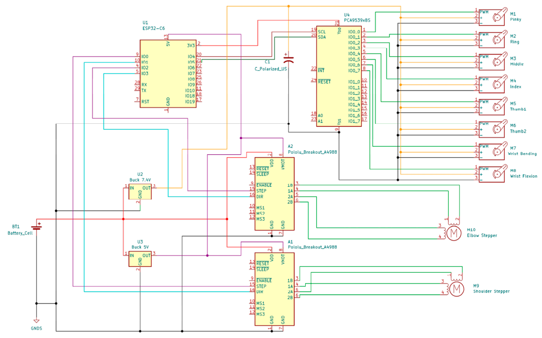
A simplified circuit diagram of the arm is shown in Figure 6. An OVONIC 4 s 2200 mAh 14.8 V 35C LiPo battery (Aethereality Company Limited, Guildford, UK) powers the system and is connected to a SNAP ACTION 2-TO-6 wiring block (Adafruit, Brooklyn, NY, USA). The wiring block has wires that directly connect to the stepper motor’s DRV 8825 expansion board (Jeanoko, Shenzhen, China) for the stepper power supply, wires that connect to an XL4015 5A 75W DC-DC Step Down Power Module (Shanghai Xinlong Semiconductor Development, Shanghai, China) that is set to 7.4 V to power the servo power rails, and an XL4015 that is set at 5 V for the logic power of the ESP32-C6 (Espressif Systems, Shanghai, China) and the stepper drivers. The buck converters were chosen because they can handle the arm’s operating loads and offer higher efficiency than linear regulators. The wires leading to the servo power rail have two 1000 µF bulk decoupling capacitors to help with current surges from the servos under load. The servos’ ground and PWM wires are connected to a PCA9685 servo driver board (AITRIP, Shenzhen Weijin Weiye Technology Co., Shenzhen, China) that provides smooth motor control. A 16 AWG wire connects the battery to the buck converter and the servo rail because, under a higher-voltage load from the battery, it has better electrothermal properties than smaller wires. The wrist pronation/supination servomotor is DS3235 (ZOSKAY, Shenzhen, China; operating voltage: 5–7.4 V; max. stall torque: 35 kg-cm at 7.4 V; corresponding speed 0.11 s/60°; total travel angle: 270°; weight: 60 g; dimensions: 40.5 × 20 × 37 cm), whereas the wrist flexion/extension servomotor is RDS3235 (ANINIMOS, China; dual bearing; same specifications as DS3235 but total travel angle is 180° and dimensions are 40 × 20 × 40 cm). A 22 AWG wire is used for logic wiring. Figure A1 in Appendix B shows the detailed arm wiring diagram.
Figure 6.
Maestro Arm’s simplified circuit diagram.
2.1.3. Elbow and Shoulder Actuation Mechanisms
The design of Maestro Arm’s actuation system addressed the critical challenge of balancing high torque and weight requirements of a WRA. The arm uses NEMA 17 stepper motors (OMC Co., Ltd., Nanjing, China), which are compact and weigh only 280 g. To manage static and dynamic loads on the robotic arm, the Maestro Arm’s actuators use multistage cycloidal and pulley speed reduction to increase the torque of the stock NEMA 17 stepper motor. Operating on a rolling contact principle, the internal transmission relies on a central eccentric shaft. As the eccentric shaft rotates, it forces the dual cycloidal disks to orbit eccentrically inside the housing ring pins. Because the disks have one fewer lobe than the ring pins, they are driven into a highly constrained reverse rotation that amplifies output torque.
The shoulder actuator achieves a 600:1 total speed reduction through three steps. First, the motor output drives an 80:20 ratio timing belt for the initial 4:1 reduction. This pulley is directly coupled to the central eccentric shaft of the cycloidal core, which drives the dual-shifted cycloidal disks in a rolling motion against the outer housing ring pins, as seen in Figure 7a. This compact reduction method provides a 30:1 speed reduction within the shoulder actuator housing. The cycloidal drive’s output rotation then drives a 10-tooth pulley, which connects via a high-torque drive (HTD) belt to a 50-tooth output pulley for the final 5:1 reduction.
Figure 7.
(a) Shoulder actuator, (b) elbow actuator.
Assuming an ideal transmission and a NEMA 17 stepper motor torque of 0.42 Nm, this 600:1 ratio would correspond to a theoretical output torque of approximately 252 Nm. However, the experimentally achieved torque was 17 Nm, corresponding to an effective torque amplification of 40.5× and an estimated overall transmission efficiency of approximately 6.7%. Beyond this experimentally determined torque of 17 Nm, the 3D-printed cycloidal output disk/carrier would fail. This lower measured value is attributed to friction, belt and bearing losses, compliance, manufacturing tolerances, alignment errors, and failure limits of the 3D-printed cycloidal components. Therefore, the 600:1 represents the kinematic speed-reduction ratio, whereas 40.5:1 represents the experimentally observed torque amplification ratio. A metallic cycloidal component may permit higher structural limits, but this possibility requires redesign and experimental validation and is not evaluated in the present study. This 40.5× torque amplification allows the fully extended Maestro Arm to lift a 2 kg load at a rated speed of 5.5°/s, with an assembly mass of approximately 1 kg (as detailed in Section 3.2). As seen in Figure 7a, the shoulder actuator has a compact design that concentrates the assembly mass at the axis of rotation. This configuration reduces the system’s rotational inertia, ensuring reliable operation without increasing motor demand.
The elbow actuator uses a 2-stage hybrid approach to achieve a compact 100:1 total speed reduction. The first stage transfers torque to an 80:20 ratio timing belt that drives a GT2 belt for a 4:1 reduction. Like the shoulder actuator, the pulley rotates the eccentric shaft of a 25:1 cycloidal drive. To minimize the cantilevered mass of the below-the-shoulder arm, the generatively designed forearm directly integrates the cycloidal drive outer roller pins, as seen in Figure 7b. This multistage reduction allows for a nominal 100:1 speed-reduction ratio while maintaining a compact elbow joint. Based on the nominal motor torque of 0.42 Nm, the ideal output torque would be 42 Nm. The measured output torque was 8.5 Nm, corresponding to an effective torque amplification of 20.2× and an estimated overall transmission efficiency of approximately 20.2%. This lower measured value is also attributed to friction, losses, compliance, tolerance, alignment errors, and failures in 3D-printed components. Delivering a 20.2-fold torque increase enabled carrying a 5 kg load at a peak velocity of 36°/s while maintaining a total mass of 827 g. This actuator differs from traditional cycloidal gear reduction systems because the eccentric motion of the cycloidal disks directly drives the outer ring pins modeled into the load-bearing forearm.
To facilitate the integration of electronics with the modularity goal, the actuators are connected via a smart connector assembly as shown in Figure 1 and Figure 8. The connector uses a quick-disconnect magnetic pogo-pin connector system. This allows both the shoulder and elbow actuators to interface seamlessly with the microcontrollers housed on the forearm. By maintaining the physical connectors, the Maestro Arm can be easily detached for maintenance or reconfiguration for different mounting forms without rewiring the whole system.
Figure 8.
Forearm-to-upper-arm smart connector.
2.1.4. The Maestro Attachment System
In wearable robotics, a main design challenge is minimizing self-collision between the user and the robotic arm. Because the device operates near the body, overlapping between the robot workspace and the user’s natural motion space can lead to an unintended contact, reducing both safety and usability. Although shoulder-mounted configurations may provide greater reach and dexterity, prior work suggests that they can also increase workspace overlap and collision risk. Nakabayashi et al. [14] found that, for human-sized wearable robotic arms, shoulder-mounted configurations interfered more with the user’s workspace than waist-mounted configurations, largely because the shoulder-mounted arm followed a trajectory similar to that of the human arm. This suggests that lower attachment locations, such as the hip or waist, may reduce overlaps with critical upper-body motion zones and thereby lower the risk of self-collision. These findings informed the decision to pursue a hip-mounted design because of its relative simplicity and its potential to reduce interference with the user’s natural upper-body motion. A hip-mounted system also offers practical mechanical advantages. Positioning the robotic arm near the waist places the support structure closer to the body’s core, which can simplify load transfer and provide more stable mounting. From an ergonomic perspective, the hip and waist are well suited to supporting external loads, since the torso is commonly used as a primary load-bearing region in wearable systems.
Inspired by quick-connect mechanisms used in aerospace suit interfaces, the Maestro Back Attachment System (MBAS) functions as a conduit that securely couples the robotic arm to the user. To engage the system, the arm is inserted into the connector housing and then manually twisted into position, as shown in Figure 9a. Once fully seated, a spring-loaded locking mechanism slides upward to engage, securing the arm in place and mechanically integrating it with the user. This also allows users to operate the system from a stable external platform, such as a table or a wheelchair.
Figure 9.
(a) Back attachment connector, (b) the Maestro back attachment system.
Attached directly to the connector is an aluminum support structure that routes the arm around the user’s body to a practical working position, as shown in Figure 9b. A key feature of this structure is its telescoping capability, which allows the user to manually adjust the arm position relative to the body. This adjustability improves comfort and adaptability across different tasks, body sizes, and loading conditions. The telescoping mechanism consists of two aluminum tubes (1 in and 7/8 in) coupled through a 1 in-to-7/8 in snap-lock interface. The system is joined using a 3D-printed acrylonitrile butadiene styrene (ABS) generatively designed 90-degree corner bracket, fabricated at a 45-degree print orientation to promote more uniform mechanical properties along the primary load path.
2.2. Foot Controller
2.2.1. Maestro Step Design
The “Maestro Step” foot controller system, shown in Figure 10a in an exploded view, builds on previous versions of the Infinity and Infinity-2 foot controllers [31,32]. It communicates wirelessly with the robotic arm to fully control all actuators. The insole is 3D-printed from Thermoplastic Polyurethane (TPU), with elastic bands sewn on so it can be worn with or without a shoe. TPU was chosen for the insole for its flexibility, which makes it comfortable for the user. Two push buttons are integrated into the insole, with toe paddles placed on top to increase the surface area the toes can press. One paddle sits under the big toe, while the other sits under the four lesser toes. The insole has grooves to route wires from the toe buttons to the electronics heel housing. This housing is 3D-printed from polycarbonate (PC) and contains an ESP32-C6 microcontroller (Seeed Studio, Shenzhen, China), a BNO-055 inertial measurement unit (IMU) (Reland Sun, Shenzhen, China), and a 3.7V 500mAh 402050 LiPo battery (Liter Energy Battery, Shenzhen, China). 3D-printed PC was chosen because of its high impact strength, compression strength, durability, and thermal resistance. The selected LiPo battery is thin (4 mm), leaving enough space for other electronics in the housing. The IMU contains an accelerometer, gyroscope, and magnetometer, all of which are used in detecting ankle movements and foot gestures. The electronics housing is located in the heel to capture the highest-quality IMU data. Previous designs [31,32] had electronic components located in a clip-on housing or on a strap next to the user’s ankle. However, the Maestro Step integrates all electronics within the insole to prevent unclipping and unintended or accidental IMU movement during use. For user comfort and symmetry, a passive insole for the opposite foot has also been fabricated, as shown in Figure 10b.
Figure 10.
(a) “Maestro Step” assembly, (b) right foot controller and left passive insole.
2.2.2. Electronics Heel Housing Simulation
To protect the electronic components, the heel housing must be stiff and strong enough to withstand user-induced compression forces, avoid damaging fragile electronic components, and prevent safety hazards from the LiPo battery. The design, shown in Figure 11a, features a ribbed structure over the LiPo battery and supports that connect the two housing halves, distributing force from the top of the housing to the ground and reducing deflection. Finite element analysis (FEA) simulation was performed in SOLIDWORKS Simulation (2025) on the complete housing, after achieving mesh convergence, to determine the deflection under load. With an applied load of 2670 N—determined by the average weight of an adult man (890 N) and a factor of safety of 3—the simulation showed a maximum deflection of 1 mm, as shown in Figure 11b. This is well under the 4 mm gap between the housing lid and the LiPo battery.
Figure 11.
(a) Electronics heel housing, (b) distribution of the resultant displacement of the heel housing FEA model.
2.2.3. Maestro Step Control System
The Maestro Step foot controller is designed to operate 10 DOFs of the Maestro robotic arm while using only two push buttons and the IMU sensor. To control the arm with minimal input and simplify training, the two push buttons control the fingers, while the IMU controls wrist, elbow, and shoulder movements. Furthermore, the foot controller also integrates a Machine Learning (ML) model to add more distinct control commands. Figure 12 shows an overview of how the Maestro Step foot controller operates the arm.
Figure 12.
Maestro Step control system architecture diagram.
Pressing and holding the big toe button initiates gradual finger flexion (closing), while pressing and holding the small toes button produces gradual finger extension (opening). This gradual motion lets users fully control the robotic hand’s opening and closing and adjust grip force, preventing slippage or crushing the gripped item. Pressing buttons in sequence switches between different grip configurations. The available grip types include “one,” “two,” “three,” “four,” “power,” “pinch,” “tripod,” and “thumb-up.” The “one” through “four” configurations enable numerical gestures, while the “pinch” grip allows picking up objects using the thumb and index fingers. The “tripod” grip extends this capability by incorporating the middle finger for enhanced stability. The “power” grip engages all fingers to produce the strongest gripping force. The “thumb-up” configuration produces a thumbs-up gesture.
Pressing both toe buttons simultaneously activates the gesture recognition mode, allowing additional control functions. Figure 13 shows the logic diagram for the gesture recognition mode. During gesture recognition mode, the arm is prevented from moving so users can perform foot gestures without worrying about accidental arm movement. For the next 1.5 s, the ML model trained using a Convolutional Neural Network (CNN) classifies the gesture performed (more details in Section 2.2.4). Depending on the gesture, the arm performs a specific task, such as switching between joints to actuate, changing the arm speed, and returning to the default position. If no foot gesture is performed or the CNN cannot recognize the gesture, nothing happens, and the arm returns to its initial state. If users accidentally trigger gesture recognition mode, they can press both toe buttons again to exit early.
Figure 13.
Gesture recognition mode logic diagram.
Using different foot-tapping gestures, the user can switch actuation between the three joints (shoulder, elbow, and wrist). As can be seen in Figure 14, ankle dorsiflexion (raising the forefoot) results in a rising joint movement (wrist extension, elbow flexion, or shoulder flexion), whereas ankle plantarflexion (lowering the forefoot by raising the heel) results in a lowering joint movement (wrist flexion, elbow extension, or shoulder extension), depending on the current actuation mode of the robotic arm. Since the wrist joint has two DOFs while the elbow and shoulder joints have only one DOF, ankle inversion and eversion control wrist supination and pronation in all three actuation modes.
Figure 14.
Corresponding arm motions to foot motions.
The Maestro Step also allows for speed adjustment of the robotic arm. Lateral movement—swiping—of the foot is used to change the speed: swiping left decreases speed, whereas swiping right increases it, as shown in Figure 12. This enables users to control the arm more precisely in different environments. For instance, slower speeds are recommended when operating near obstacles, such as while seated at a table, to minimize collision risk. In open spaces, higher speeds are preferred to complete tasks quickly. To prevent unwanted motion, threshold values are applied to the roll and pitch angles, ensuring minor or incidental foot movements do not trigger arm motion. When users want the arm to quickly return to its default position, speed, and grip type, they can perform the heel click gesture by bringing the heel of the foot with the controller to touch the heel of the other foot, as shown in Figure 12.
To avoid unwanted motion while walking, the walking-detection algorithm freezes the arm once it detects walking. As shown in Figure 15, the magnitudes of the 3-dimensional IMU acceleration and gyroscope readings are compared to predefined threshold values. The walking-detection thresholds were selected during preliminary engineering trials to provide a conservative software interlock. Once a threshold is crossed, the code puts the arm into a “sleep mode” for 3 s. While in this mode, the arm freezes and cannot move. If the arm is “awake” and the values of the pitch and roll angles lie within a boundary, the arm will actuate the corresponding joint. The boundary for the pitch and roll values was set so that, if users want to rest their foot, the arm would not move suddenly. The present study did not quantify walking-detection sensitivity, false-negative rate, or false-positive rate during intended stationary use. Accordingly, the walking-detection function is presented as a safety-oriented design feature rather than a validated safety-performance result.
Figure 15.
Logic chart of the walking detection system.
2.2.4. Neural Network for Gesture Recognition
The ML model developed to classify the performed gestures uses a CNN because it can effectively capture local temporal patterns in IMU data. To train the model, a data-collection procedure was developed to avoid bias and improve reliability. The participants were five males from the research team-members/authors, with a mean age of 24 years and a mean weight of 68 kg. First, the participant put on the Foot Controller designed specifically for data collection. When the participant pressed the big toe button, the IMU sent readings at 100 Hz for 1.5 s (exactly 150 signals), and the data was saved as a .csv file. The chosen readings included triaxial acceleration (ax, ay, and az) and roll, pitch, and yaw angles. Afterward, the participant began data collection by pressing the big toe button and immediately performing the specified gestures. Participants recorded 40 trials for each of the six gesture types: 20 while standing and 20 while sitting on a chair. A total of 1200 samples were collected from the five participants combined. The CNN consists of two one-dimensional convolutional layers followed by max pooling, global average pooling, a fully connected layer, and, lastly, a SoftMax output for classification. The model was trained using the Adam optimizer and categorical cross-entropy loss. Leave-one-participant-out cross-validation was performed using five folds. In each fold, data from four participants were used for training, while all data from the remaining participant was reserved for testing. The fold-specific test accuracies were 93.1%, 95.1%, 93.0%, 88.8%, and 97.3%, yielding a mean accuracy of 93.4% ± 3.1% (range: 88.8–97.3%). As a separate exploratory evaluation, two additional individuals from the research team who were not included in model training performed 120 gestures. The model correctly classified 119 gestures, corresponding to an accuracy of 99.2%. Because the training, testing, and validation sets were limited, these results should not be interpreted as establishing generalizability to the broader population of potential users. Future work would evaluate gesture-recognition performance across broader variation in sex, age, gait characteristics, and foot morphology.
2.2.5. Digital Twin Models
Bug fixing and testing are crucial to developing the robotic arm and foot controller. However, testing the control system is not viable when the physical prototype is not ready. Therefore, digital twins of the Maestro Arm and the Maestro Step foot controller were developed to replace the physical models and support testing. The digital twin models were developed in Python (3.14). Figure 16a shows the graphical user interface (GUI) of the digital version of the Maestro Step. The nine sliding bars represent the IMU readings (acceleration, gyroscopic velocities, and Euler angles in 3 dimensions). While the sliding bars do not accurately represent real IMU data, the trial emulation feature can replay previously recorded foot gestures. The two red buttons represent the big and small toe buttons on the physical foot controller. The digital Maestro Step controller can control both digital and physical robotic arms. This approach helps isolate and identify potential issues with the robotic arm itself, avoiding foot controller errors and speeding up the bug-fixing process. On the other hand, Figure 16b shows the digital model of the Maestro Arm. Each component is represented as a mesh derived from STL files (exported from the Maestro Arm CAD model) and assembled via Unified Robot Description Format (URDF).
Figure 16.
(a) Maestro Step foot controller digital twin, (b) Maestro arm digital twin.
To ensure identical behavior between the digital and physical arms, a Python code was developed to access the sketch uploaded to the ESP32-C6-WROOM 1 through the USB port. When the ESP32-C6 board is connected to the digital arm, the Pulse Width Modulation (PWM) values for each servo are sent to the Python script, actuating the digital arm. Using these PWM values and the PyBullet library, the digital arm moved accordingly using both digital and physical foot controllers.
2.3. Manufacturing and Assembly
2.3.1. Maestro Hand
The Maestro hand is made primarily from three 3D-printed materials: polylactic acid (PLA), ABS, and TPU. PLA was used for all finger components because it prints easily and captures fine details. This material was also used for the hand’s back casing and the thumb phalanges, using a gyroid infill pattern for structural integrity. Because ABS is more heat-resistant and durable than PLA, it was used to print the palm and the base of the thumb, since they contact the servomotors, which generate heat during long operations. TPU was used for the flexible ligaments that connect the phalanges of each finger. These flexible ligaments are secured with bolts that thread into heat inserts on the respective finger phalanges. Figure 17a shows the components of each finger, and Figure 17b shows the complete hand prototype, which weighs 296 g. The thickest point from the palm to the back cover measured 46.5 mm. The index finger and thumb weigh 24 g and 18.4 g, respectively.
Figure 17.
(a) Finger components, (b) physical hand model (front, side, isometric, and back views).
2.3.2. Forearm
The forearm internal structure was 3D-printed in carbon-fiber-reinforced nylon (Fiberon PA6-CF20; JF Polymers, Changshu, China) due to its high specific stiffness and thermal resistance. A hardened steel nozzle, recommended for abrasive materials, was used, and the nozzle and bed temperatures were set to 300 °C and 100 °C, respectively. This bed temperature ensured proper bed adhesion and reduced warping, especially for long prints. The cooling fan was turned off per the manufacturer’s recommendation, and the printing speed was reduced to 200 mm/s to improve layer adhesion and surface quality. The filament was also dried for 12 h at 85 °C. After printing and removing all supports, the part was annealed using the two-stage annealing process discussed further in Section 3.1. M2 and M3 heat inserts were used to mount the electronics and ensure a secure fit. All wires were cut to the exact length needed to connect each component, with no overlap with the forearm composite shell that protects all components. The final part weighs 91.6 g, as shown in Figure 18a.
Figure 18.
(a) Final manufactured Maestro generative-designed forearm, (b) composite shell for forearm.
Two composite shells were manufactured using a traditional wet layup procedure to protect the electronics housed in the forearm. Two male molds were first 3D-printed in PLA, and three plies oriented at [0°/45°/0°] were stacked in the composite wet layup process (0° represents the arm’s longitudinal direction). The Fibre Glast 2000 (Laminating Epoxy Resin; Fibre Glast Developments Corp LLC; Brookville, OH, USA) and Fibre Glast 2060 (Hardener) were mixed with a 4:1 ratio and were applied to each layer. Figure 18b shows the prototype shells and their molds.
2.3.3. Actuation
The elbow actuator structure and cycloidal disks were 3D-printed from Polyethylene Terephthalate Glycol (PETG). The elbow actuator was assembled using low-friction ball bearings and PTFE-fortified silicone lubricant to minimize friction and ensure smooth power transmission throughout the cycloidal reduction stage. Figure 19a shows the assembled elbow actuator of the prototype arm. The cycloidal disks, housing, belt tensioners, and output pulley in the shoulder were all 3D-printed in PETG. The cycloidal drive output and eccentric shaft were 3D-printed in Fiberon PA6-CF20 because these parts experience the highest mechanical loads. Figure 19b shows the assembled shoulder actuator of the prototype arm. The forearm-to-upper-arm smart connector was also 3D-printed and assembled, as shown in Figure 20, to enable detaching the forearm and hand subsystem from the rest of the arm, if needed.
Figure 19.
(a) Arm prototype’s elbow actuator, (b) Arm prototype’s shoulder actuator.
Figure 20.
Modular actuator assembly.
2.3.4. Back Attachment System
The belt serves as the main interface between the user and the support structure. A commercially available sports belt that was originally intended to carry a pole and a camera on the back was used. To adapt this belt for the application, the original camera mount was removed, and the 3D-printed connector was attached to the belt using screws. The sports belt featured flexible leather that conformed more naturally to the user’s body, improving comfort under load. It also simplified attaching and removing the remaining system components. Several structural components of the back attachment were 3D-printed in ABS due to its toughness. Since many of these components are load-bearing, print orientation was an important factor in the manufacturing process. Each part was oriented so the primary loads act along the printed layers rather than across them, preventing elevated interlayer shear loads and delamination. The commercially available telescoping aluminum tubes were cut to the correct length, and the whole back connector assembly was connected to the shoulder. Figure 21a shows the fully assembled prototype.
Figure 21.
(a) Fully assembled Maestro Arm prototype, (b) manufactured heel housing.
2.3.5. Foot Control
The servomotor used for the arm’s wrist pronation/supination is a 270-degree servo. The zero position for this servo is set so that the hand in the handshake position is at 135°, so left and right palm rotations match the allowable rotation of a human’s hand. This also avoids twisting the finger servo wires too far and pulling them out of their connection to the servo driver board.
The foot insoles were 3D-printed in 95A HF TPU (Bambu Lab, Shenzhen, China), as shown in Figure 10b. The heel housing was 3D-printed in PC, as shown in Figure 21b. For PC 3D-printing, the initial layer height and layer line width were increased, an 8 mm wide brim was added, and cooling was disabled for the first 5 layers to improve bed adhesion. Additionally, the filament was stored in an airtight filament drying station, dried at 80 °C for 8 h, and then dried again at that temperature during each print to reduce water absorption and improve print quality. Teflon tubing connected the drying station to the printer to eliminate air contact time for the filament. A 0.4 mm hardened steel nozzle ensured the full volume of extruded filament melted sufficiently. The build plate was cleaned with dish soap and rubbing alcohol to ensure adequate adhesion.
Assembly of the foot controller, shown in Figure 22a,b, starts with soldering Qwiic Connect wires (elechawk, Shenzhen, China) to the ESP32 GPIO pins; the other end of each Qwiic Connect wire connects to the IMU. Next, two strands of 24 AWG wire were soldered to each toe button and run through the channel in the center of the foot insole. The ground wires were twisted, pre-tinned, and then soldered to the GND port on the IMU. Hot glue held the two toe buttons in place and secured the wires connecting them to the other electronic components. The LiPo battery was then connected to the ESP32 via the JST 2.0 mm connector, and, finally, the heel housing lid was closed using a press fit with the base to enclose all components. The elastic straps were cut to length; Velcro pieces approximately 1.5 cm wide were sewn in, then fed through the holes in the foot insole and connected at the bottom.
Figure 22.
(a) Collected electronic components, (b) electronic components.
3. Results
3.1. Material Characterization Testing
Because the final forearm design was not 3D-printed with 100% infill, the mechanical properties Fusion used to produce the generative design model were inaccurate due to the significant difference in mechanical properties. To obtain more realistic material properties, tensile testing was conducted on 12 ASTM D638 Type IV specimens, all with 3 walls, divided into 2 categories: 20% infill, non-annealed, and 20% infill, annealed. The infill pattern selected for the tensile coupons was gyroid, a bio-inspired infill pattern with improved stress distribution and energy absorption [37]. The specimens were printed in the XY direction, which differs from the manufacturer’s Z orientation [38]. The annealing process is a two-stage annealing process described by Liu et al. [39]. This process improves mechanical properties by aligning the fibers with the crystallization direction at high temperature. The annealing cycle that was implemented, shown in Figure 23, had an initial ramp from room temperature to 80 °C at 1 °C/min, then stage 1 at 80 °C for 5 h, continued with another ramp up to 145 °C at 1 °C/min, then stage 2 at 145 °C for 5 h, followed by slow cooling at 1 °C/min until reaching room temperature.
Figure 23.
Two-stage annealing cycle.
The non-annealed samples shown in Figure 24a fractured along the interface between layers rather than failing cleanly in the transverse plane because of poor matrix adhesion. In the annealed samples (Figure 24b), failure was consistent in the transverse plane and also showed brittle behavior, as shown in Figure 24c. Table 2 lists all extracted material properties from the stress–strain curves. The measured increase in mechanical properties was similar to what Liu et al. [32] reported for the two-stage annealing process. Approximately, the annealed samples had a 40% reduction in failure strain, but a 74% increase in Young’s modulus, a 53% increase in yield strength, and a 30% increase in ultimate strength. For the final design, the 20% gyroid infill with annealing was selected because it showed the most superior mechanical properties.
Figure 24.
Tensile testing: (a) non-annealed samples, (b) annealed samples, and (c) stress–strain plot.
Table 2.
Material Properties for Carbon-fiber-reinforced Nylon 6 (Fiberon PA6-CF20).
To validate the structural integrity of the 3D-printed forearm structure, physical testing was conducted in which the part was fixed at the elbow, and a dead weight was slowly suspended at the tip. The structure withstood 40 lbs (approximately 18.14 kg) without visual deformation. This results in an approximate experimental static load ratio of 6.0 relative to the design load. The generative design model used equivalent material properties and did not explicitly account for the anisotropic behavior of the fused-filament-fabricated structure. In particular, the analysis did not consider the effects of print orientation, layer-to-layer adhesion, raster direction, or infill-dependent properties. These factors, together with STL geometry conversion and differences in boundary conditions and load application, may have contributed to the difference between the target numerical FOS (1.5) and the experimentally observed FOS (6.0). Because the prototype did not fail during testing, the result is reported as survival at approximately six times the design load rather than as a definitive ultimate FOS.
To test the effectiveness of the Maestro hand prototype, multiple tests were performed to assess the hand’s ability to perform various tasks and grip everyday items. Figure 25 shows an initial actuation test where full actuation of each finger was checked while performing different grips, such as pointing one, two, three, four, pinch, tripod, thumbs up, and power grip.
Figure 25.
Testing dexterity of the hand through gestures: (a–d) numbers 1–4. (e) pinch, (f) tripod, (g) thumbs-up.
A grasping test was conducted to assess how well the hand can hold everyday items of various shapes, sizes, and weights. Table 3 lists the items that were gripped and shown in Figure 26. The Maestro hand prototype successfully held all items with ease, showing no signs of slippage or unstable grasping. Because the ARC joint fingers can dislocate, the fingers were shown to be compliant and adapt to the gripped item to ensure a stable grip. Video S1 in the Supplementary Materials demonstrates the Maestro Arm performing various tasks controlled by the Maestro Step foot controller.
Table 3.
List of items used to assess grasping capabilities.
Figure 26.
Hand holding various items.
To characterize hand strength, a grip test was conducted. The Baseline Evaluation Instruments’ digital dynamometer (grip model; Fabrication Enterprises Inc., White Plains, NY, USA) was used to measure grip force. The dynamometer was set up on a rigid wooden plate and angled to ensure proper contact with the fingers. A total of 10 test trials were conducted, as shown in Figure 27a,b. The average grip force was 1.88 kg (18.44 N) with a standard deviation of 0.148 kg (1.45 N).
Figure 27.
Grip strength test: (a) test setup, (b) finger actuation during the test.
A pulling test was also conducted on the hand using the Dr. Meter scale (max 110 lb/50 kg) and a gripper the hand could hold, as shown in Figure 28a. The scale was mounted above the hand, which was fixed to its base. The test was terminated once the fingers lost contact with the gripper. The achieved pulling force was 6.8 kg (66.69 N). No failures in the hand were observed, further illustrating the benefits of rolling-contact joints. The pulling test was also conducted on the thumb separately to identify potential failure points. The thumb was directly hooked up to the Dr. Meter scale (Figure 28b) and was pulled at an angle to resist the 2 DOF thumb servo motors. At a load of 7.6 kg (74.56 N), the 3D-printed thumb base failed.
Figure 28.
(a) Pulling test (whole hand), (b) pulling test (thumb).
3.2. Elbow and Shoulder Actuation System Testing
To validate the elbow and shoulder actuator design, both systems underwent different tests to ensure sufficient torque, operational speed, and structural integrity. As seen in Figure 29a, the elbow actuator was evaluated using a stationary mount configuration. Testing involved incremental load application, ranging from 200 g to 5 kg. Because the elbow actuator operates in the horizontal plane, testing primarily focused on the structural performance of the PA6-CF generative-design forearm and the PETG actuator housing. Throughout the full 180-degree range of motion, the system maintained control without visible deflection of the elbow actuator housing. It was concluded that the elbow’s failure mode was not motor stalling, but structural limits of the 3D-printed components.
Figure 29.
(a) Elbow joint torque testing with suspended load, (b) shoulder actuator torque test, (c) shoulder actuator shaft failure.
Because the shoulder actuator needed to lift the entire assembly and the weight of the object it held, the design required more robust testing, as shown in Figure 29b. The shoulder actuator was mounted to a table, and testing started at 250 μs, with weights ranging from 2 kg to 9 kg. One main challenge during testing was the inverse relationship between angular velocity and torque output. This common problem is seen in high-reduction stepper motor systems. As the pulse delay decreased to increase angular speed, the pull-out torque decreased. Table 4 identifies the optimal pulse delays and corresponding angular speeds for different loading scenarios. While the faster speed seems suitable for everyday tasks, the torque output is not sufficient to actuate the entire assembly with a weight greater than 2 kg. When testing the shoulder actuator at its fastest speed, the failure modes were characterized by an audible high-pitched sound coming from the stepper motor with no movement. In contrast, when testing the shoulder actuator at 1500 μs or 2000 μs, the torque increased significantly. Although the speed decreased to around 1° per second, the shoulder actuator lifted 9 kg before failure was observed in the output pulley shaft (Figure 29c). These results represent stationary actuator testing rather than a validated payload specification for the complete wearable system.
Table 4.
Speed and weight test on the shoulder actuator.
3.3. Foot Controller Testing
To ensure the completed heel housing can support the user’s full weight, compression testing was performed. Participants (from the research team) of increasing weight walked 21 m with the heel housing inside the insole, which was placed under their feet in the shoe. After each participant, the structural integrity of the heel housing was checked for signs of deformation or fracture. The tests showed that a participant weighing 1312 N could walk with the heel housing without any signs of fracture, providing a factor of safety of at least 1.5, with the average weight of an adult man being approximately 890 N.
3.4. Battery Life Testing
To determine the subsystems’ actual working life, battery life testing was performed. Constant-use life for the arm was determined by running the system continuously for 40 min on a fully charged battery and recording the charge used. The time was then adjusted for the battery’s full-charge capacity and an estimated 80% efficiency for nonlinear discharge across the full capacity. The same test was performed for the arm in standby mode by fully powering up the system, not actuating it for 40 min, and then measuring the charge again. For the foot controller, constant-use life was calculated based on the current draw of the ESP32-C6, BNO055 IMU, and toe buttons, with an estimated efficiency of 80%. Standby mode life was determined by the ESP32-C6 current draw in deep sleep mode, with 80% efficiency. The light-use battery life was calculated based on an estimated 30 s of use every 10 min. The arm’s battery life with standby, light, and constant use was 3.5 h, 2.4 h, and 1.5 h, respectively. The foot controller’s battery life with standby, light, and constant use was three months, three days, and 3.5 h, respectively.
4. Discussion
This study evaluates the Maestro Arm as a waist-mounted supernumerary wearable robotic arm. A supernumerary arm and a transhumeral prosthesis serve different purposes and target different user populations. Although the modular attachment architecture may support future prosthetic adaptations, this work did not design, fabricate, or experimentally evaluate a transhumeral prosthesis. In particular, the study does not address socket geometry, residual-limb anatomy and interface loading, socket suspension, comfort, donning and doffing, user-specific control capabilities, user acceptance, or clinical requirements and safety. The reported 2.9 kg mass should therefore be interpreted as the mass of the wearable robotic arm prototype and not as evidence of suitability for routine trans-humeral prosthetic use. A potential nonclinical application is temporary upper-limb impairment, such as restricted arm use during injury recovery. Any future prosthetic adaptation would require a clinically appropriate socket and attachment system, as well as separate interface design, user-specific control mapping, and evaluation with individuals with limb loss.
The current 10-DOF configuration—comprising one shoulder DOF, one elbow DOF, two wrist DOFs, and six hand DOFs—is considered sufficient for the applications considered for this robotic arm. Future work will focus on optimizing these existing joints rather than adding additional DOFs. This optimization will target increased operational speeds, reduced overall weight, improved power efficiency, and enhanced durability. Characterizing current consumption for each actuator under representative payloads, motion speeds, and duty cycles would guide optimization of motor-current settings, actuator control, and battery capacity.
The present study primarily evaluated static load capacity and short-duration actuator performance; therefore, the fatigue life of the 3D-printed cycloidal components was not established. Under repeated operation, the cycloidal disks, carrier, eccentric shaft, and housing may be affected by layer-dependent fatigue, interlayer cracking, wear at the rolling contacts, deformation, creep, backlash growth, and progressive loss of transmission efficiency. Print orientation, infill pattern, material, lubrication, operating torque, and duty cycle may influence these effects. Consequently, the reported static torque capacity should not be interpreted as a long-term durability rating.
The suitability of foot control depends on the task and the user’s lower-limb capabilities. Using the foot as a control channel is advantageous when the user’s hands must remain stationary to recover from injuries, such as arm fractures and rotator-cuff surgeries, or remain available to manipulate objects or perform other tasks. It also avoids dependence on residual-limb muscle signals, which may be unavailable or unreliable for some users, and avoids the environmental and privacy limitations associated with voice control. However, foot control is not appropriate for every operating condition. The current system is not intended for active manipulation while walking or during activities that require the feet for balance, locomotion, or other control. In this work, the developed walking detection system disables arm actuation when walking is detected to reduce the possibility of unintended movement; therefore, the intended operating scenarios are primarily seated or stationary tasks in which the user’s feet are available for control, rather than continuous manipulation while ambulating. Safe arm operation during walking would require additional operating modes and dedicated validation, which would be considered in future work.
The sequential selection of multiple joints through foot gestures also involves a trade-off. It reduces the number of physical input devices required, but it may increase mode-switching time, command ambiguity, attentional demand, and the possibility of unintended commands. These cognitive and usability effects were not evaluated in the present study. Accordingly, the foot-based interface is presented as a task-specific alternative rather than a replacement for EMG or other control methods. Future work should evaluate command-selection time, error rate, workload, and learning time.
The present study evaluated gesture-classification performance and individual subsystem operation but did not quantitatively assess the complete human–robot control loop. Users were not evaluated while coordinating shoulder, elbow, wrist, and hand movements during representative manipulation tasks or while switching between control modes. Task-completion time, success rate, command errors, unintended activations, mode-switching frequency, or cognitive workload were not measured. In addition, no comparison with an alternative control strategy was performed. Therefore, these results do not establish an advantage of foot control over EMG, EEG, voice, or other control interfaces. Future work should evaluate the complete control loop during representative manipulation tasks.
The gesture-recognition dataset included only five young male participants with relatively similar demographic characteristics. Consequently, the results may not generalize to women, older adults, individuals with atypical gait patterns, or users with different foot morphologies. Broader participant recruitment and participant-independent validation are needed before drawing conclusions about inclusivity or clinical generalizability.
Walking-detection performance was not systematically evaluated across different walking speeds or ground surfaces. Variations in cadence, acceleration, terrain compliance, slope, and surface type may affect the IMU signals and the selected detection thresholds. Therefore, the current results do not establish that the walking-detection interlock performs consistently during slow or fast walking or across various surface types. Future work should evaluate detection sensitivity, false-negative rate, and false-positive rate across representative walking conditions, such as walking speeds and cadences, and, secondarily, representative surface conditions.
The 10-DOF configuration also creates a potential opportunity for shared or semiautonomous control. Rather than requiring the user to select each joint and continuously generate foot movements, a computer vision system could identify objects, estimate their pose, and suggest suitable wrist orientations or grasp configurations. The user could then provide a high-level command or confirm the proposed action, while the controller manages coordinated joint motion. Visual contextual information could therefore complement direct foot-based input and potentially reduce explicit commands, joint-switching operations, and continuous foot movements required from the user [40]. Such an architecture would also introduce additional challenges, including object-recognition errors, occlusion, camera placement, processing latency, uncertain grasp selection, and the need for a reliable user override.
The current prototype incorporates several preliminary safety mechanisms. Walking detection serves as a software interlock that inhibits arm actuation when it detects gait-related motion. During gesture-recognition mode, the system temporarily suspends arm motion while it classifies the gesture. If the system detects no valid gesture, or if the classifier does not recognize the input, it issues no additional command. The arm also operates within the mechanical and actuator limits defined by the joint designs. However, these features do not constitute a complete safety validation. The present study did not quantify unintended gesture activations, communication failures, emergency-stop response, collision avoidance, or behavior under uncertain classifications. Wireless communication loss should result in a defined fail-safe state, such as disabling actuator commands through a watchdog or timeout mechanism. These functions must be tested under representative operating conditions before the system can be considered suitable for extended or unsupervised use.
5. Summary and Conclusions
The mechanical design of the Maestro Arm shows functionality and modularity. The tendon-driven hand achieved 6 DOFs and high gripping strength, with measured grip and pulling forces of 18.44 N and 66.69 N, respectively. The generatively designed forearm survived a static load of 18 kg, while housing all necessary electronics within a lightweight structure. Shoulder cycloidal actuation tests showed a trade-off between speed and load capacity. Under the tested stationary conditions, the actuator lifted 2 kg at approximately 5.5°/s and up to 9 kg at approximately 1°/s. Meanwhile, the Maestro Step foot controller showed potential as a feasible control solution. By combining two toe-actuated push buttons with an IMU sensor, the system enables control of up to 10 DOF of the robotic arm. Using leave-one-participant-out cross-validation, the trained CNN achieved a mean participant-independent test accuracy of 93.4% ± 3.1% across five held-out participants, with individual fold accuracies ranging from 88.8% to 97.3%. In a separate exploratory evaluation involving two additional research-team members, the model correctly classified 119 of 120 gestures (99.2%). Furthermore, safety features such as walking detection were incorporated to reduce the risk of unwanted robotic-arm motion while the foot is moving.
Overall, the results demonstrate the feasibility of the Maestro Arm as a modular waist-mounted wearable robotic arm controlled through the Maestro Step foot controller. The external attachment concept supports reconfiguration for different non-clinical mounting scenarios, while its potential application to prosthetic use remains a topic for future investigation. The foot-based interface is a hybrid body-motion and inertial control interface that was selected because it uses an available body region and avoids the need for upper-limb muscles or EMG sensors. The study presents it as a design choice rather than evidence that foot control is superior to other interfaces. Future work will focus on reducing system mass, improving power efficiency, developing and validating appropriate user-specific attachment interfaces, and optimizing the walking-detection system performance.
Supplementary Materials
The following supporting information can be downloaded at https://www.mdpi.com/article/10.3390/robotics15100182/s1, Video S1: Maestro Arm and Foot Controller.
Author Contributions
Conceptualization, P.L.B., K.Y., Y.T., S.D.R., J.B., H.P., M.P., K.S., K.T., C.F. and A.A.-D.; methodology, P.L.B., K.Y., Y.T., S.D.R., J.B., H.P., M.P., K.S., K.T., C.F. and A.A.-D.; software, P.L.B., K.Y., Y.T., S.D.R., J.B., H.P., M.P., K.S., K.T., C.F. and A.A.-D.; validation, P.L.B., K.Y., Y.T., S.D.R., J.B., H.P., M.P., K.S., K.T., C.F. and A.A.-D.; formal analysis, P.L.B., K.Y., Y.T., S.D.R., J.B., H.P., M.P., K.S., K.T., C.F. and A.A.-D.; investigation, P.L.B., K.Y., Y.T., S.D.R., J.B., H.P., M.P., K.S., K.T., C.F. and A.A.-D.; resources, P.L.B.; data curation, P.L.B., K.Y., Y.T., S.D.R., J.B., H.P., M.P., K.S., K.T., C.F. and A.A.-D.; writing—original draft preparation, P.L.B., K.Y., Y.T., S.D.R., J.B., H.P., M.P., K.S., K.T., C.F. and A.A.-D.; writing—review and editing, P.L.B.; visualization, P.L.B., K.Y., Y.T., S.D.R., J.B., H.P., M.P., K.S., K.T., C.F. and A.A.-D.; supervision, P.L.B.; project administration, P.L.B.; funding acquisition, P.L.B. All authors have read and agreed to the published version of the manuscript.
Funding
This research received no external funding.
Institutional Review Board Statement
The CSUN Committee for the Protection of Human Subjects determined that this study did not constitute human-subjects research and therefore did not require IRB approval or exemption. All data collection and preliminary testing were performed by members of the research team. Informed consent has been obtained.
Data Availability Statement
The raw data supporting the conclusions of this article will be made available by the authors on request.
Acknowledgments
This work was done by the ninth cohort of the “Smart Prosthetics” research-based senior design project at California State University, Northridge (CSUN). The authors acknowledge the Mechanical Engineering Department, the Instructionally Related Activities (IRA) grant, the Faculty Research Project Development Initiative (FRPDI) grant, and the Student Travel and Academic Research (STAR) program at CSUN.
Conflicts of Interest
The authors declare no conflicts of interest.
Appendix A. Comparing Maestro Arm Against Other WRAs in the Literature
Table A1.
Sample Wearable Robotic Arm designs in the literature.
Appendix B. Arm Wiring Diagram
Figure A1.
Maestro arm’s wiring diagram.
References
- Zheng, S.; Li, M.; Zheng, Y.; Tao, T.; Xie, J.; Xu, G. Supernumerary Robotic Limbs: A Quantitative Analysis and Review of Design, Embodiment, and Future Challenges. J. Field Robot. 2026, 43, 3120–3145. [Google Scholar] [CrossRef] [Scilit]
- Guo, W.; Xu, W.; Zhao, Y.; Shi, X.; Sheng, X.; Zhu, X. Toward Human-in-the-Loop Shared Control for Upper-Limb Prostheses: A Systematic Analysis of State-of-the-Art Technologies. IEEE Trans. Med. Robot. Bionics 2023, 5, 563–579. [Google Scholar] [CrossRef] [Scilit]
- Vidal, C.; Lira, M.J.; De Marinis, R.; Liendo, R.; Contreras, J.J. Increasing Incidence of Rotator Cuff Surgery: A Nationwide Registry Study in Chile. BMC Musculoskelet. Disord. 2021, 22, 1052. [Google Scholar] [CrossRef] [Scilit]
- Rivera, J.A.; Churovich, K.; Anderson, A.B.; Potter, B.K. Estimating Recent US Limb Loss Prevalence and Updating Future Projections. Arch. Rehabil. Res. Clin. Transl. 2024, 6, 100376. [Google Scholar] [CrossRef] [Scilit]
- Martinez-Hernandez, U.; Metcalfe, B.; Assaf, T.; Jabban, L.; Male, J.; Zhang, D. Wearable Assistive Robotics: A Perspective on Current Challenges and Future Trends. Sensors 2021, 21, 6751. [Google Scholar] [CrossRef] [Scilit]
- Yanik, E.L.; Chamberlain, A.M.; Keener, J.D. Trends in Rotator Cuff Repair Rates and Comorbidity Burden among Commercially Insured Patients Younger than the Age of 65 Years, United States 2007–2016. JSES Rev. Rep. Tech. 2021, 1, 309–316. [Google Scholar] [CrossRef] [Scilit]
- Bai, S.; Virk, G.S.; Sugar, T.G. (Eds.) Soft Wearable Assistive Robotics: Exosuits and Supernumerary Limbs. In Wearable Exoskeleton Systems: Design, Control and Applications; Institution of Engineering and Technology: London, UK, 2018; pp. 219–254. [Google Scholar]
- Alsuradi, H.; Hong, J.; Mazi, H.; Eid, M. Neuro-Motor Controlled Wearable Augmentations: Current Research and Emerging Trends. Front. Neurorobot. 2024, 18, 1443010. [Google Scholar] [CrossRef] [Scilit]
- Salminger, S.; Stino, H.; Pichler, L.H.; Gstoettner, C.; Sturma, A.; Mayer, J.A.; Szivak, M.; Aszmann, O.C. Current Rates of Prosthetic Usage in Upper-Limb Amputees—Have Innovations Had an Impact on Device Acceptance? Disabil. Rehabil. 2022, 44, 3708–3713. [Google Scholar] [CrossRef] [Scilit]
- Kojima, A.; Yamazoe, H.; Lee, J.-H. Wearable Robot Arm with Consideration of Weight Reduction and Practicality. JRM 2020, 32, 173–182. [Google Scholar] [CrossRef] [Scilit]
- Parietti, F.; Asada, H.H. Dynamic Analysis and State Estimation for Wearable Robotic Limbs Subject to Human-Induced Disturbances. In Proceedings of the 2013 IEEE International Conference on Robotics and Automation, Karlsruhe, Germany, 6–10 May 2013; IEEE: Piscataway, NJ, USA, 2013; pp. 3880–3887. [Google Scholar]
- Parietti, F.; Chan, K.C.; Hunter, B.; Asada, H.H. Design and Control of Supernumerary Robotic Limbs for Balance Augmentation. In Proceedings of the 2015 IEEE International Conference on Robotics and Automation (ICRA), Seattle, WA, USA, 26–30 May 2015; IEEE: Piscataway, NJ, USA, 2015; pp. 5010–5017. [Google Scholar]
- Veronneau, C.; Denis, J.; Lebel, L.-P.; Denninger, M.; Plante, J.-S.; Girard, A. A Lightweight Force-Controllable Wearable Arm Based on Magnetorheological-Hydrostatic Actuators. In Proceedings of the 2019 International Conference on Robotics and Automation (ICRA), Montreal, QC, Canada, 20–24 May 2019; IEEE: Piscataway, NJ, USA, 2019; pp. 4018–4024. [Google Scholar]
- Nakabayashi, K.; Iwasaki, Y.; Takahashi, S.; Iwata, H. Experimental Evaluation of Cooperativeness and Collision Safety of a Wearable Robot Arm. In Proceedings of the 2018 27th IEEE International Symposium on Robot and Human Interactive Communication (RO-MAN), Nanjing, China, 27–31 August 2018; IEEE: Piscataway, NJ, USA, 2018; pp. 1026–1031. [Google Scholar]
- Drohne, L.; Nakabayashi, K.; Iwasaki, Y.; Iwata, H. Design Consideration for Arm Mechanics and Attachment Positions of a Wearable Robot Arm. In Proceedings of the 2019 IEEE/SICE International Symposium on System Integration (SII), Paris, France, 14–16 January 2019; IEEE: Piscataway, NJ, USA, 2019; pp. 645–650. [Google Scholar]
- Chen, Z.; Min, H.; Wang, D.; Xia, Z.; Sun, F.; Fang, B. A Review of Myoelectric Control for Prosthetic Hand Manipulation. Biomimetics 2023, 8, 328. [Google Scholar] [CrossRef] [Scilit]
- Chadwell, A.; Kenney, L.; Thies, S.; Head, J.; Galpin, A.; Baker, R. Addressing Unpredictability May Be the Key to Improving Performance with Current Clinically Prescribed Myoelectric Prostheses. Sci. Rep. 2021, 11, 3300. [Google Scholar] [CrossRef] [Scilit]
- Franzke, A.W.; Kristoffersen, M.B.; Bongers, R.M.; Murgia, A.; Pobatschnig, B.; Unglaube, F.; Van Der Sluis, C.K. Users’ and Therapists’ Perceptions of Myoelectric Multi-Function Upper Limb Prostheses with Conventional and Pattern Recognition Control. PLoS ONE 2019, 14, e0220899. [Google Scholar] [CrossRef] [Scilit]
- Biddiss, E.A.; Chau, T.T. Upper Limb Prosthesis Use and Abandonment: A Survey of the Last 25 Years. Prosthet. Orthot. Int. 2007, 31, 236–257. [Google Scholar] [CrossRef] [Scilit]
- Bandara, D.S.V.; Arata, J.; Kiguchi, K. Towards Control of a Transhumeral Prosthesis with EEG Signals. Bioengineering 2018, 5, 26. [Google Scholar] [CrossRef] [Scilit]
- Applications of Brain-Computer Interfaces to the Control of Robotic and Prosthetic Arms. In Handbook of Clinical Neurology; Elsevier: Amsterdam, The Netherlands, 2020; Volume 168, pp. 87–99.
- Bishay, P.L.; Fontana, J.; Raquipiso, B.; Rodriguez, J.; Borreta, M.J.; Enos, B.; Gay, T.; Mauricio, K. Development of a Biomimetic Transradial Prosthetic Arm with Shape Memory Alloy Muscle Wires. Eng. Res. Express 2020, 2, 035041. [Google Scholar] [CrossRef] [Scilit]
- Bonilla, B.L.; Asada, H.H. A Robot on the Shoulder: Coordinated Human-Wearable Robot Control Using Coloured Petri Nets and Partial Least Squares Predictions. In Proceedings of the 2014 IEEE International Conference on Robotics and Automation (ICRA), Hong Kong, China, 31 May–7 June 2014; IEEE: Piscataway, NJ, USA, 2014; pp. 119–125. [Google Scholar]
- Bishay, P.; Aguilar, C.; Amirbekyan, A.; Vartanian, K.; Arjon-Ramirez, M.; Pucio, D. Design of a Lightweight Shape Memory Alloy Stroke-Amplification and Locking System in a Transradial Prosthetic Arm. In Proceedings of the ASME 2021 Conference on Smart Materials, Adaptive Structures and Intelligent Systems, Virtual, Online, 14–15 September 2021; American Society of Mechanical Engineers: New York, NY, USA, 2021; p. V001T05A015. [Google Scholar]
- Karrenbach, M.; Boe, D.; Sie, A.; Bennett, R.; Rombokas, E. Improving Automatic Control of Upper-Limb Prosthesis Wrists Using Gaze-Centered Eye Tracking and Deep Learning. IEEE Trans. Neural Syst. Rehabil. Eng. 2022, 30, 340–349. [Google Scholar] [CrossRef] [Scilit]
- Muehlhaus, M.; Koelle, M.; Saberpour, A.; Steimle, J. I Need a Third Arm! Eliciting Body-Based Interactions with a Wearable Robotic Arm. In Proceedings of the 2023 CHI Conference on Human Factors in Computing Systems, Hamburg Germany, 23–28 April 2023; ACM: New York, NY, USA, 2023; pp. 1–15. [Google Scholar]
- Drăgoi, M.-V.; Frimu, A.-V.; Postelnicu, A.; Puiu, R.-A.; Petrea, G.; Hank, A. Interactive Teleoperation of an Articulated Robotic Arm Using Vision-Based Human Hand Tracking. Biomimetics 2026, 11, 151. [Google Scholar] [CrossRef] [Scilit]
- Greene, R.J.; Kim, D.; Kaliki, R.; Kazanzides, P.; Thakor, N. Shared Control of Upper Limb Prosthesis for Improved Robustness and Usability. In Proceedings of the 2022 9th IEEE RAS/EMBS International Conference for Biomedical Robotics and Biomechatronics (BioRob), Seoul, Republic of Korea, 21–24 August 2022; IEEE: Piscataway, NJ, USA, 2022; pp. 1–7. [Google Scholar]
- Jing, H.; Zhao, S.; Zheng, T.; Li, L.; Zhang, Q.; Sun, K.; Zhao, J.; Zhu, Y. Shared Control of Supernumerary Robotic Limbs Using Mixed Realityand Mouth-and-Tongue Interfaces. Biosensors 2025, 15, 70. [Google Scholar] [CrossRef] [Scilit]
- Cirelli, G.; Tamantini, C.; Cordella, L.P.; Cordella, F. A Semiautonomous Control Strategy Based on Computer Vision for a Hand–Wrist Prosthesis. Robotics 2023, 12, 152. [Google Scholar] [CrossRef] [Scilit]
- Bishay, P.L.; Wilgus, J.; Chen, R.; Valenzuela, D.; Medina, V.; Tan, C.; Ittner, T.; Caldera, M.; Rubalcava, C.; Safarian, S.; et al. Controlling a Below-the-Elbow Prosthetic Arm Using the Infinity Foot Controller. Prosthesis 2023, 5, 1206–1231. [Google Scholar] [CrossRef] [Scilit]
- Bishay, P.L.; Funes Alfaro, G.; Sherrill, I.; Reoyo, I.; McMahon, E.; Carter, C.; Valdez, C.; Riyaz, N.M.; Ali, S.; Lima, A.; et al. “The Foot Can Do It”: Controlling the “Persistence” Prosthetic Arm Using the “Infinity-2” Foot Controller. Technologies 2025, 13, 98. [Google Scholar] [CrossRef] [Scilit]
- Jing, X.; Yong, X.; Jiang, Y.; Li, G.; Yokoi, H. Anthropomorphic Prosthetic Hand with Combination of Light Weight and Diversiform Motions. Appl. Sci. 2019, 9, 4203. [Google Scholar] [CrossRef] [Scilit]
- Cakit, E.; Durgun, B.; Cetik, O.; Yoldas, O. A Survey of Hand Anthropometry and Biomechanical Measurements of Dentistry Students in Turkey. Hum. Factors Ergon. Manuf. Serv. Ind. 2014, 24, 739–753. [Google Scholar] [CrossRef] [Scilit]
- Ozsoy, T.; Oner, Z.; Oner, S. An Attempt to Gender Determine with Phalanx Length and the Ratio of Phalanxes to Whole Phalanx Length in Direct Hand Radiography. Med. Sci. 2019, 8, 692–697. [Google Scholar] [CrossRef] [Scilit]
- Kim, S.; Sung, E.; Park, J. ARC Joint: Anthropomorphic Rolling Contact Joint with Kinematically Variable Torsional Stiffness. IEEE Robot. Autom. Lett. 2023, 8, 1810–1817. [Google Scholar] [CrossRef] [Scilit]
- Podroužek, J.; Marcon, M.; Ninčević, K.; Wan-Wendner, R. Bio-Inspired 3D Infill Patterns for Additive Manufacturing and Structural Applications. Materials 2019, 12, 499. [Google Scholar] [CrossRef] [Scilit]
- Fiberon PA6 Manufacturer Datasheet. Available online: https://fiberon.polymaker.com/wp-content/uploads/TDS_FIBERON-PA6-CF20_V1.0_EN.pdf (accessed on 20 September 2026).
- Liu, B.; Xin, B.; Zhu, W.; Zhang, B.; Pang, Y. Two-stage Annealing Method for Short Carbon Fiber-reinforced Nylon 6 in Fused Filament Fabrication. Polym. Compos. 2025, 46, 618–631. [Google Scholar] [CrossRef] [Scilit]
- Cirelli, G.; Stefanelli, E.; Billardello, R.; Tamantini, C.; Leonelli, S.; Zollo, L.; Cordella, L.P.; Cordella, F. Context-Aware Semiautonomous Control for Upper-Limb Prostheses. Adv. Intell. Syst. 2026, 8, e202501043. [Google Scholar] [CrossRef] [Scilit]
- Veronneau, C.; Denis, J.; Lebel, L.-P.; Denninger, M.; Blanchard, V.; Girard, A.; Plante, J.-S. Multifunctional Remotely Actuated 3-DOF Supernumerary Robotic Arm Based on Magnetorheological Clutches and Hydrostatic Transmission Lines. IEEE Robot. Autom. Lett. 2020, 5, 2546–2553. [Google Scholar] [CrossRef] [Scilit]
- Vatsal, V.; Hoffman, G. Design and Analysis of a Wearable Robotic Forearm. In Proceedings of the 2018 IEEE International Conference on Robotics and Automation (ICRA), Brisbane, QLD, Australia, 21–25 May 2018; IEEE: Piscataway, NJ, USA, 2018; pp. 5489–5496. [Google Scholar]
- Vatsal, V.; Hoffman, G. The Wearable Robotic Forearm: Design and Predictive Control of a Collaborative Supernumerary Robot. Robotics 2021, 10, 91. [Google Scholar] [CrossRef] [Scilit]
- Tang, Z.; Zhang, L.; Chen, X.; Ying, J.; Wang, X.; Wang, H. Wearable Supernumerary Robotic Limb System Using a Hybrid Control Approach Based on Motor Imagery and Object Detection. IEEE Trans. Neural Syst. Rehabil. Eng. 2022, 30, 1298–1309. [Google Scholar] [CrossRef] [Scilit]
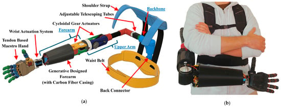
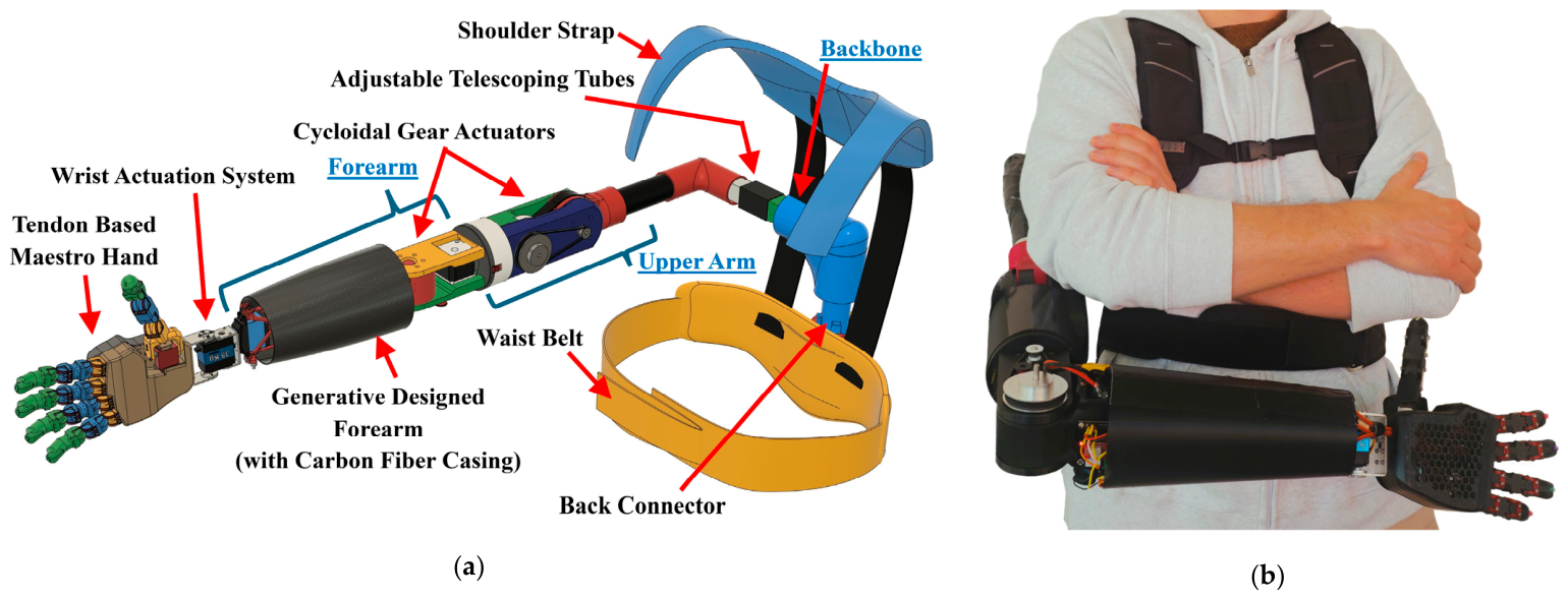
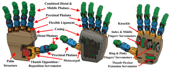
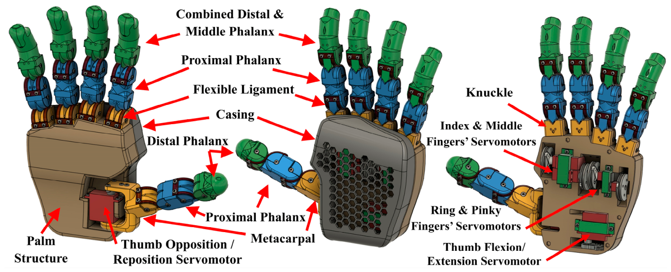
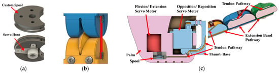
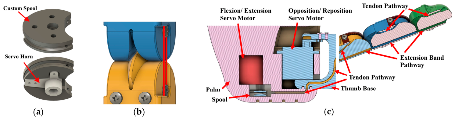
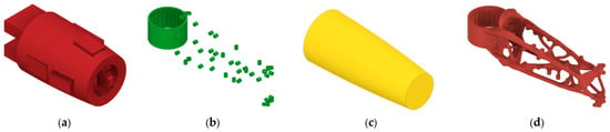
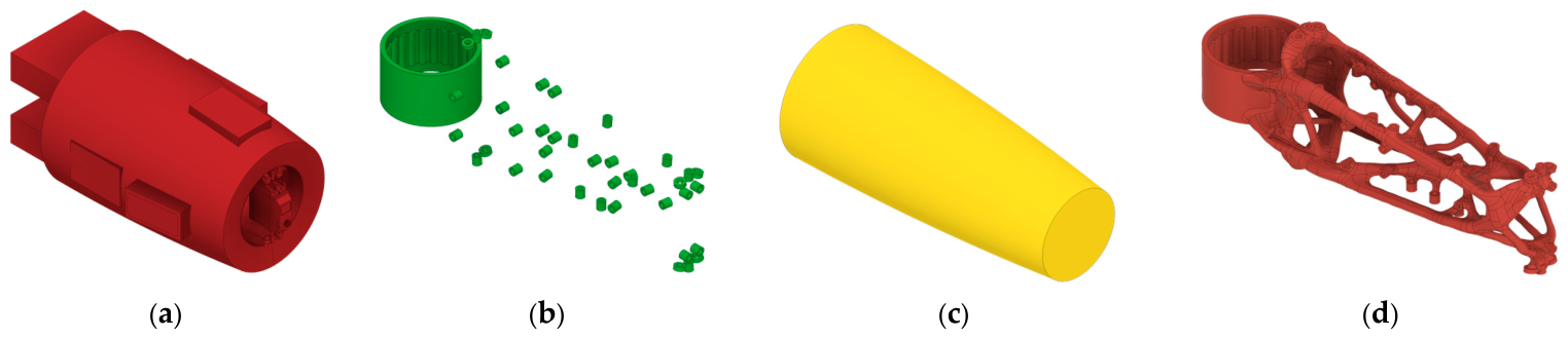
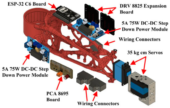
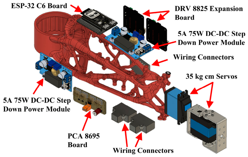
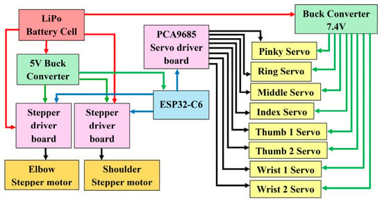
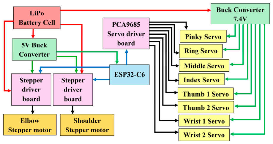
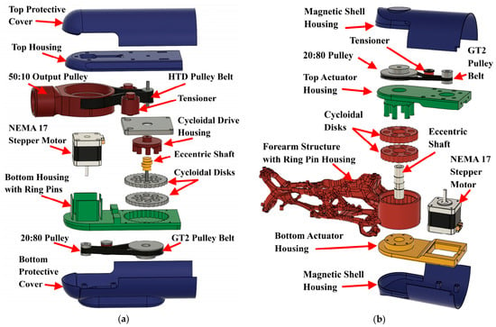
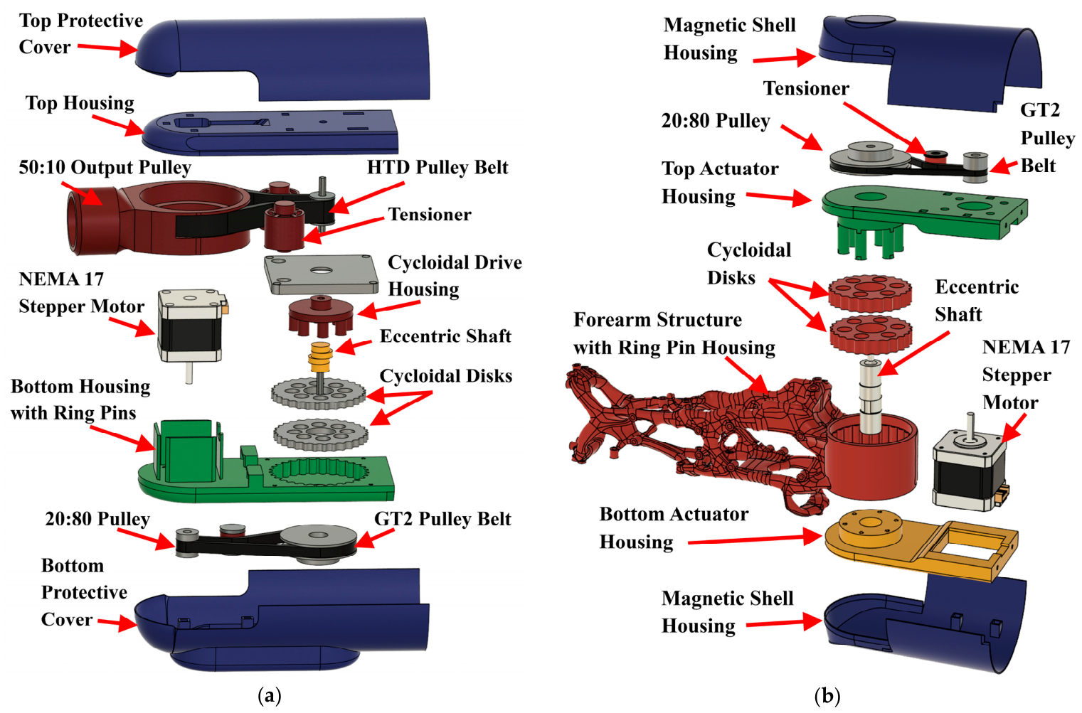
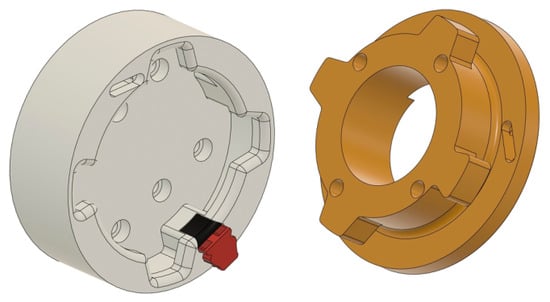
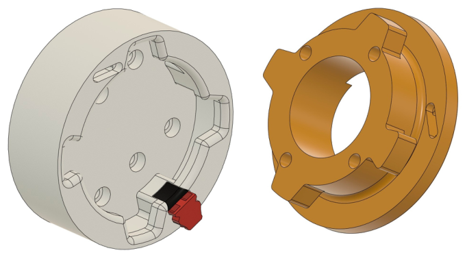
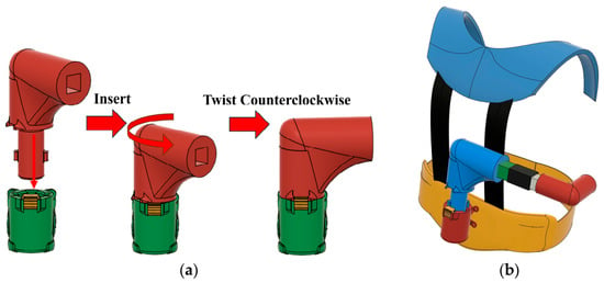
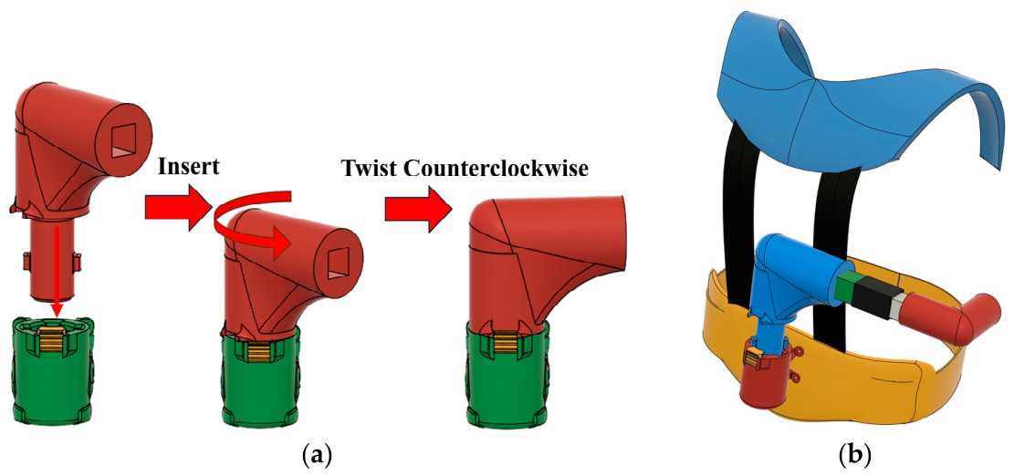
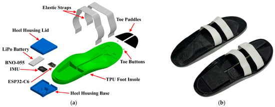
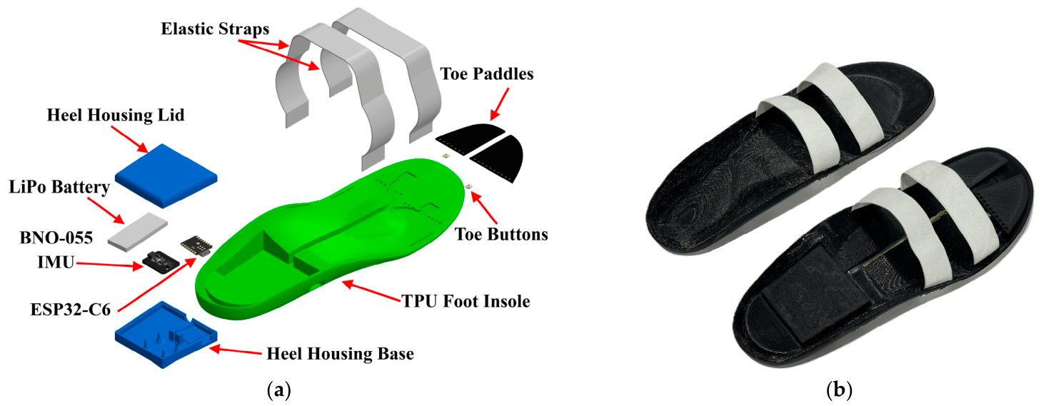
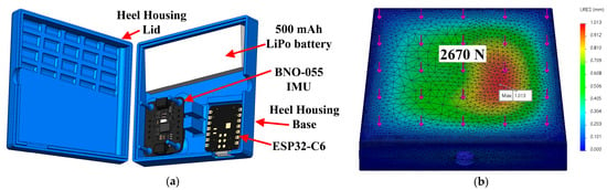
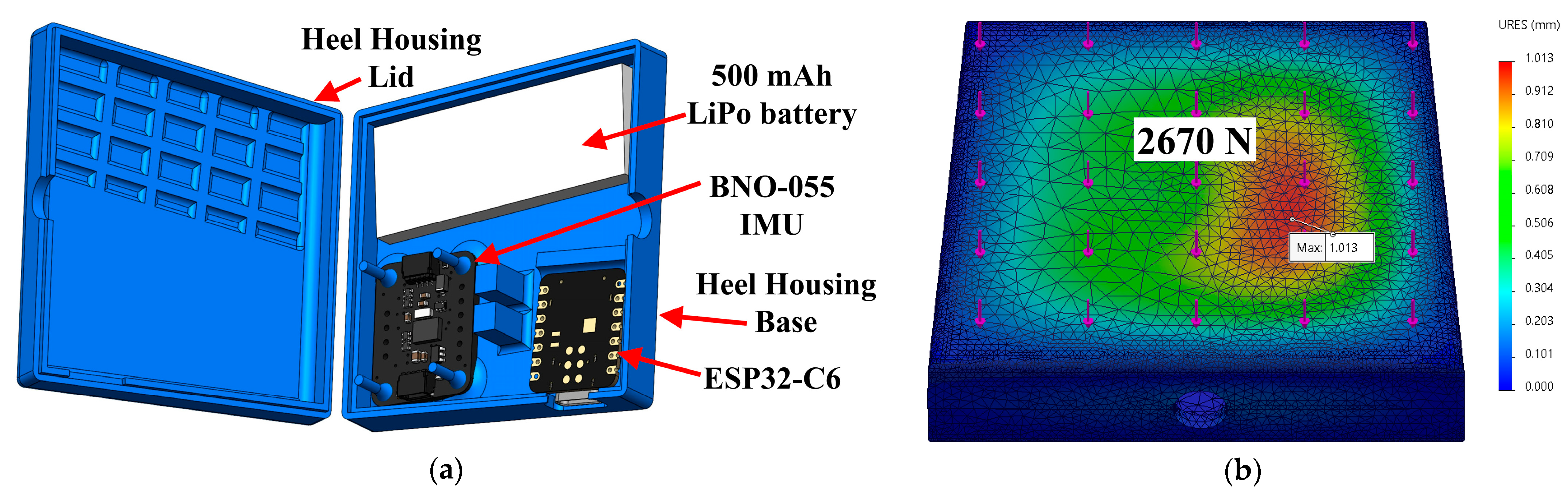
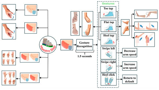
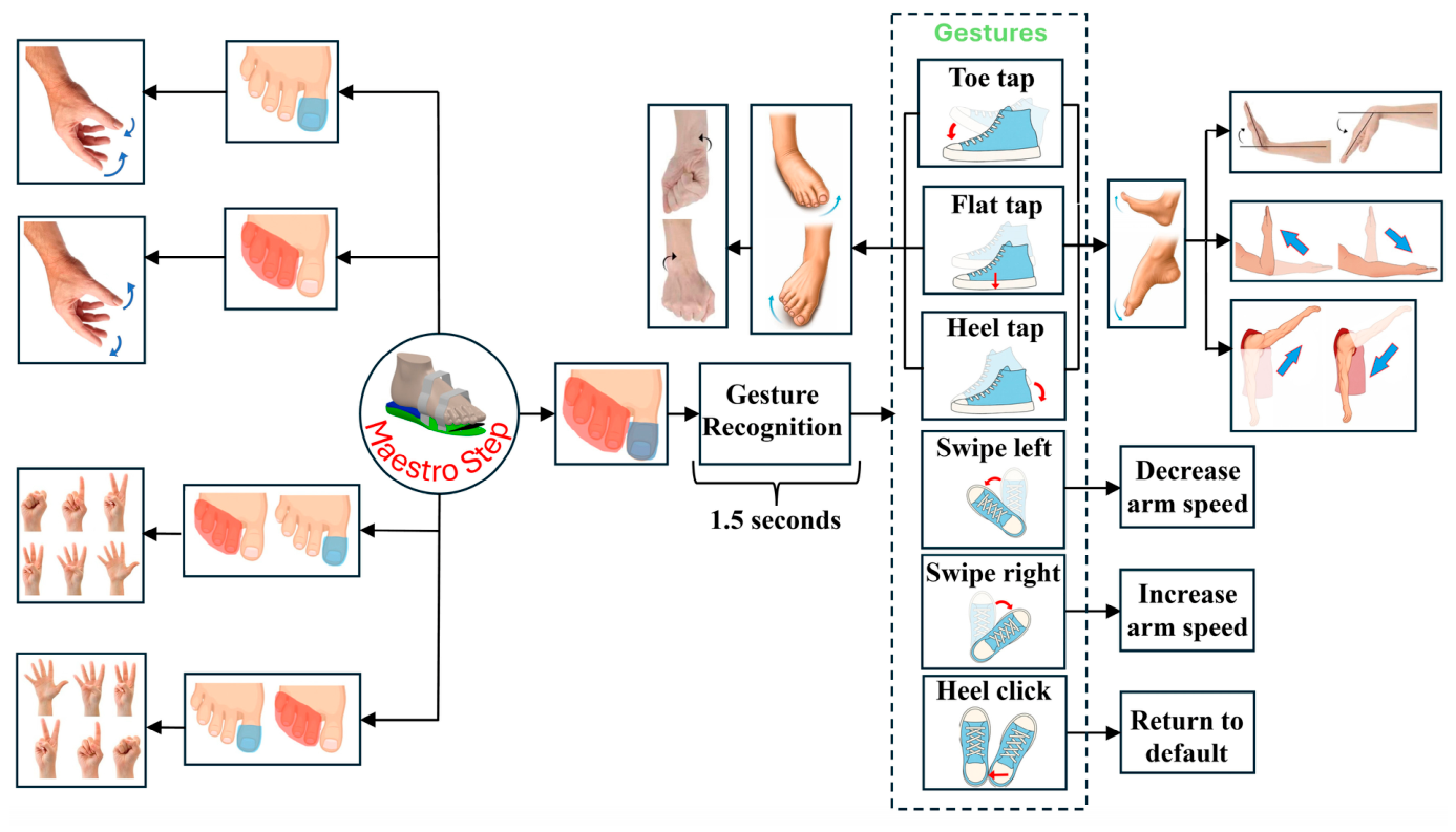
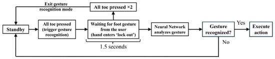
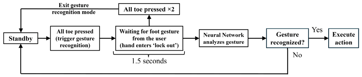
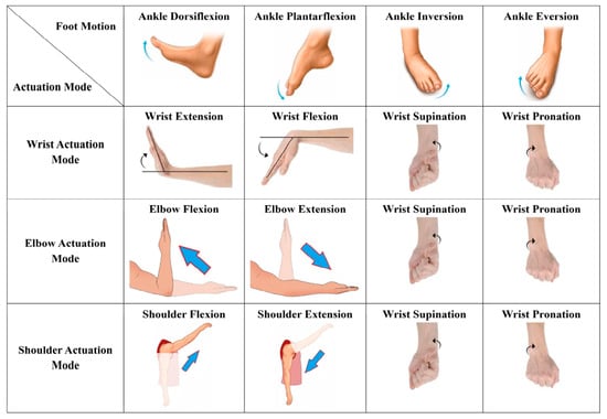
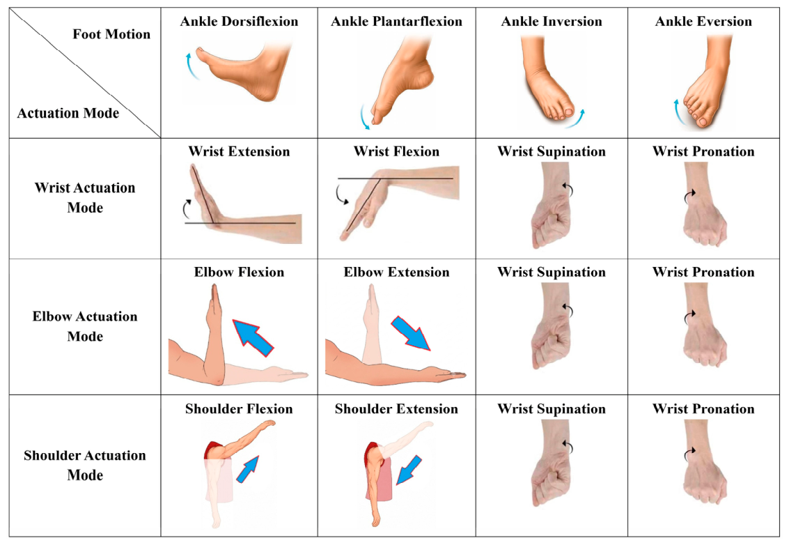
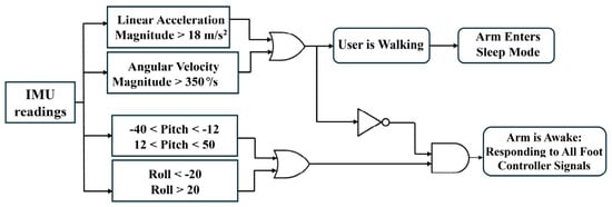
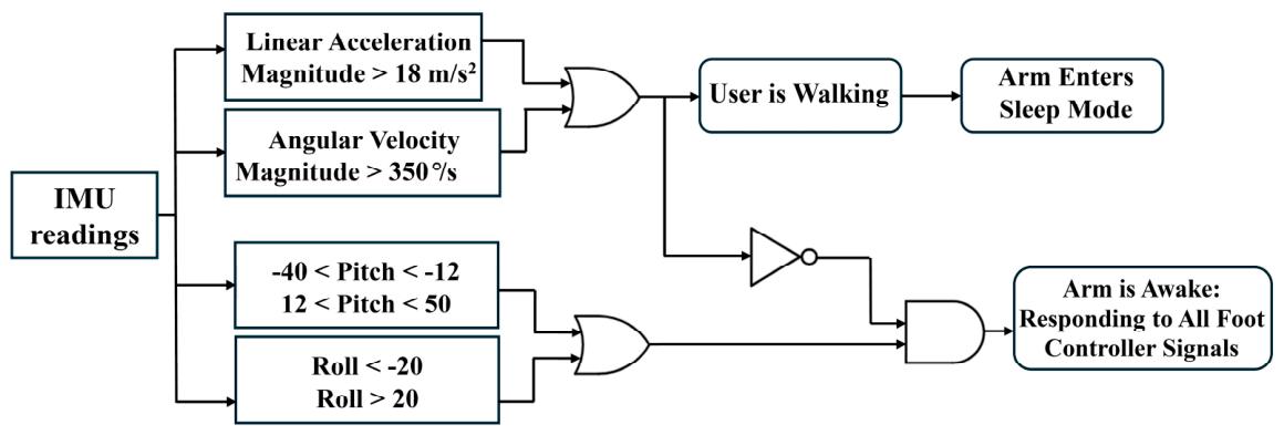
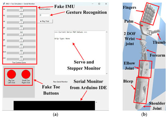
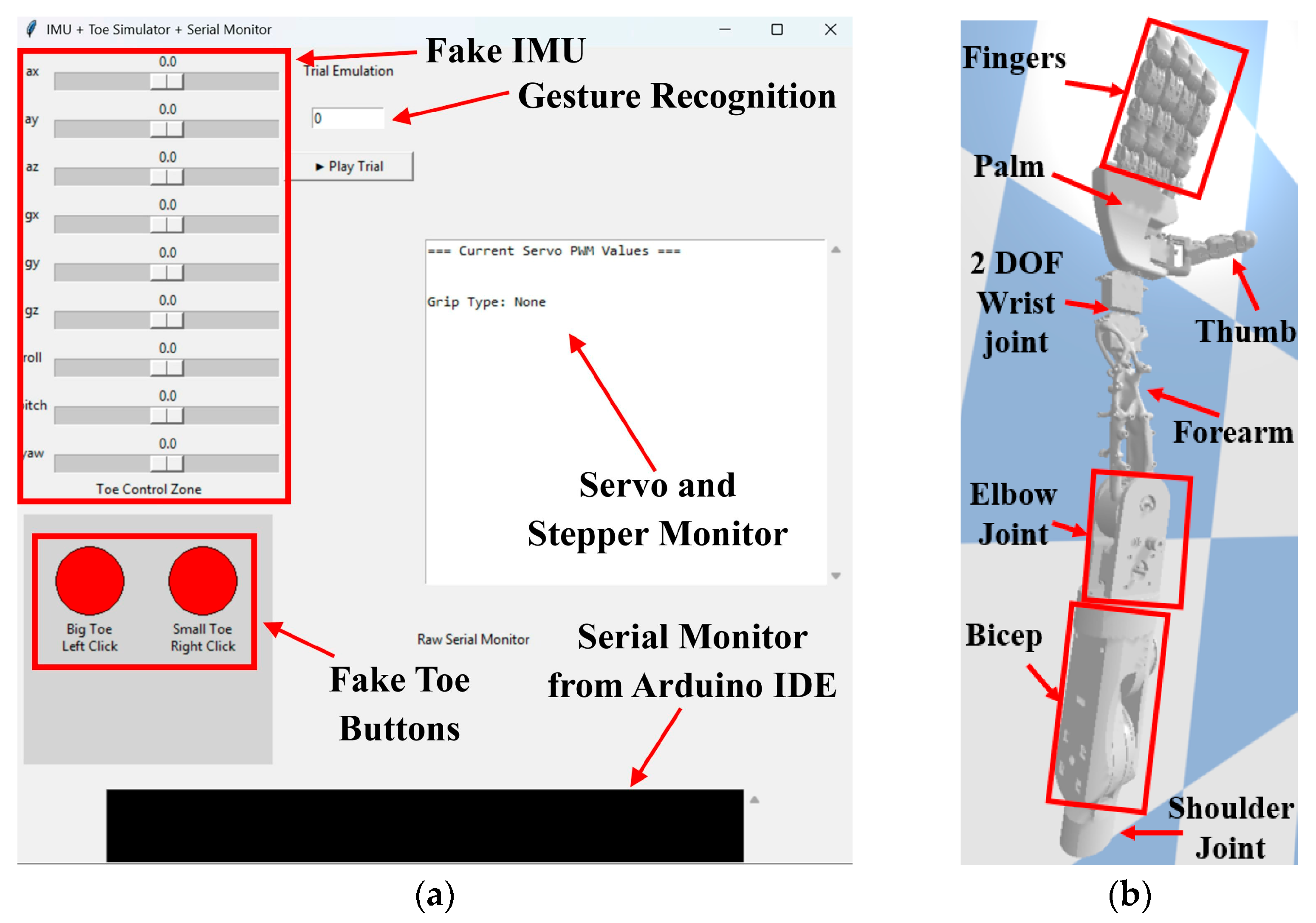
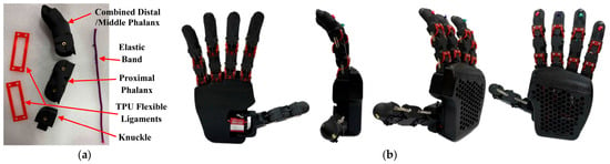
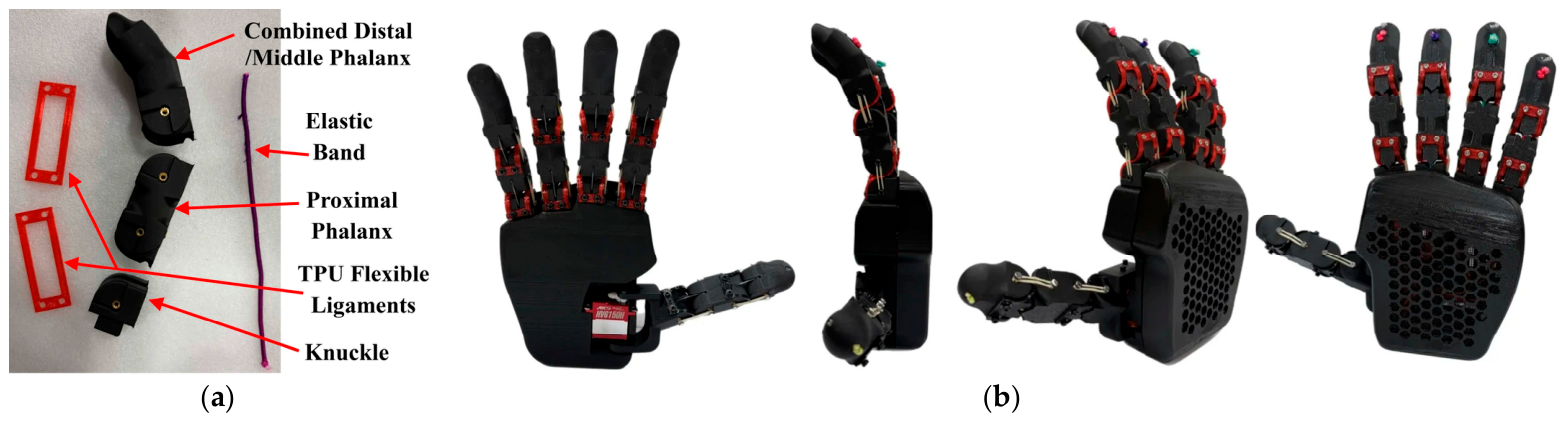
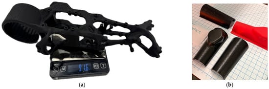
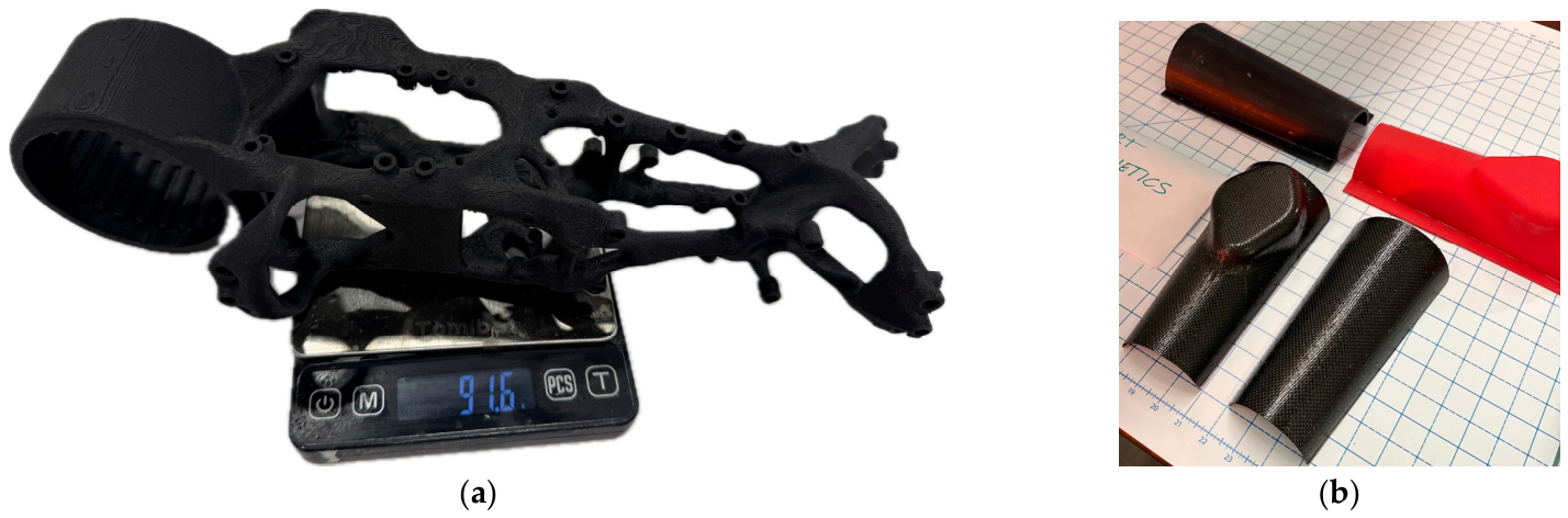
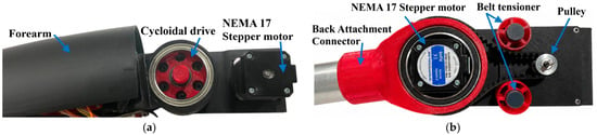
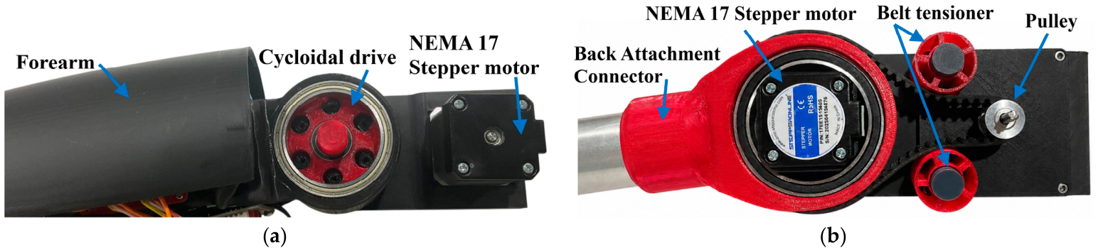
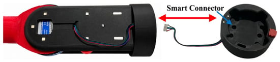
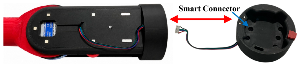
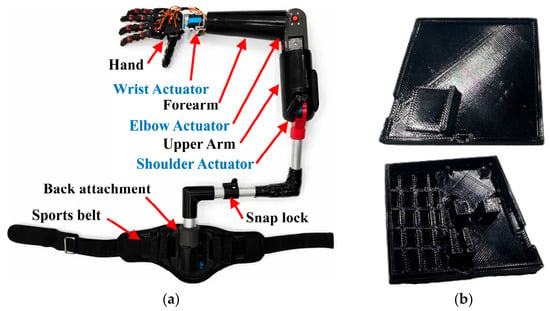
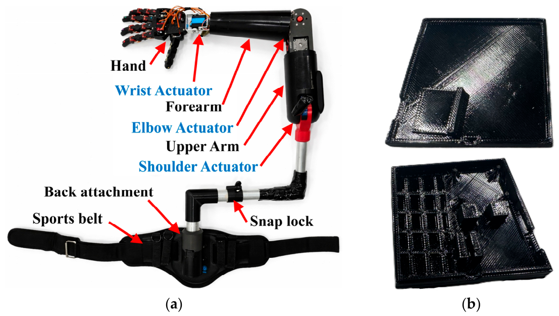
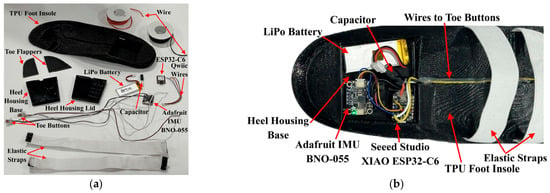
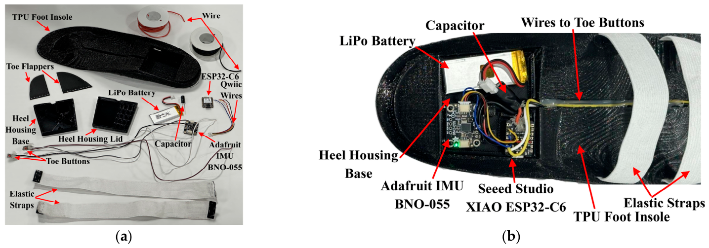
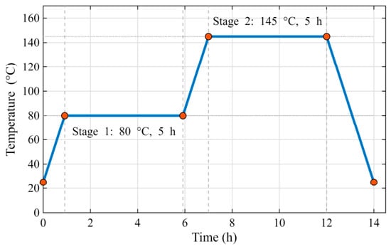
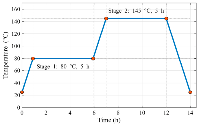
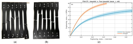
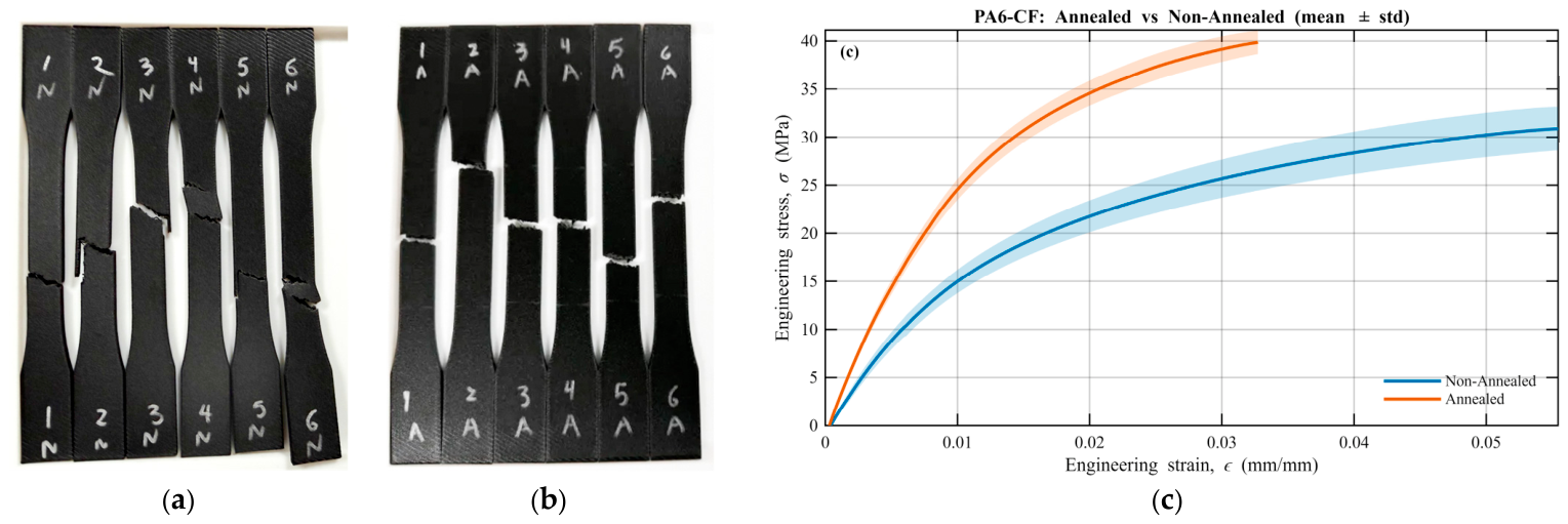
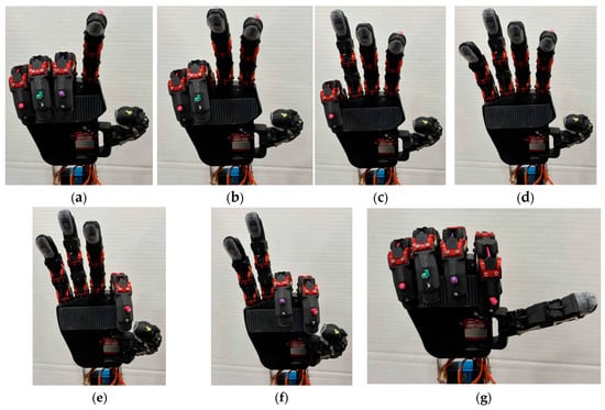
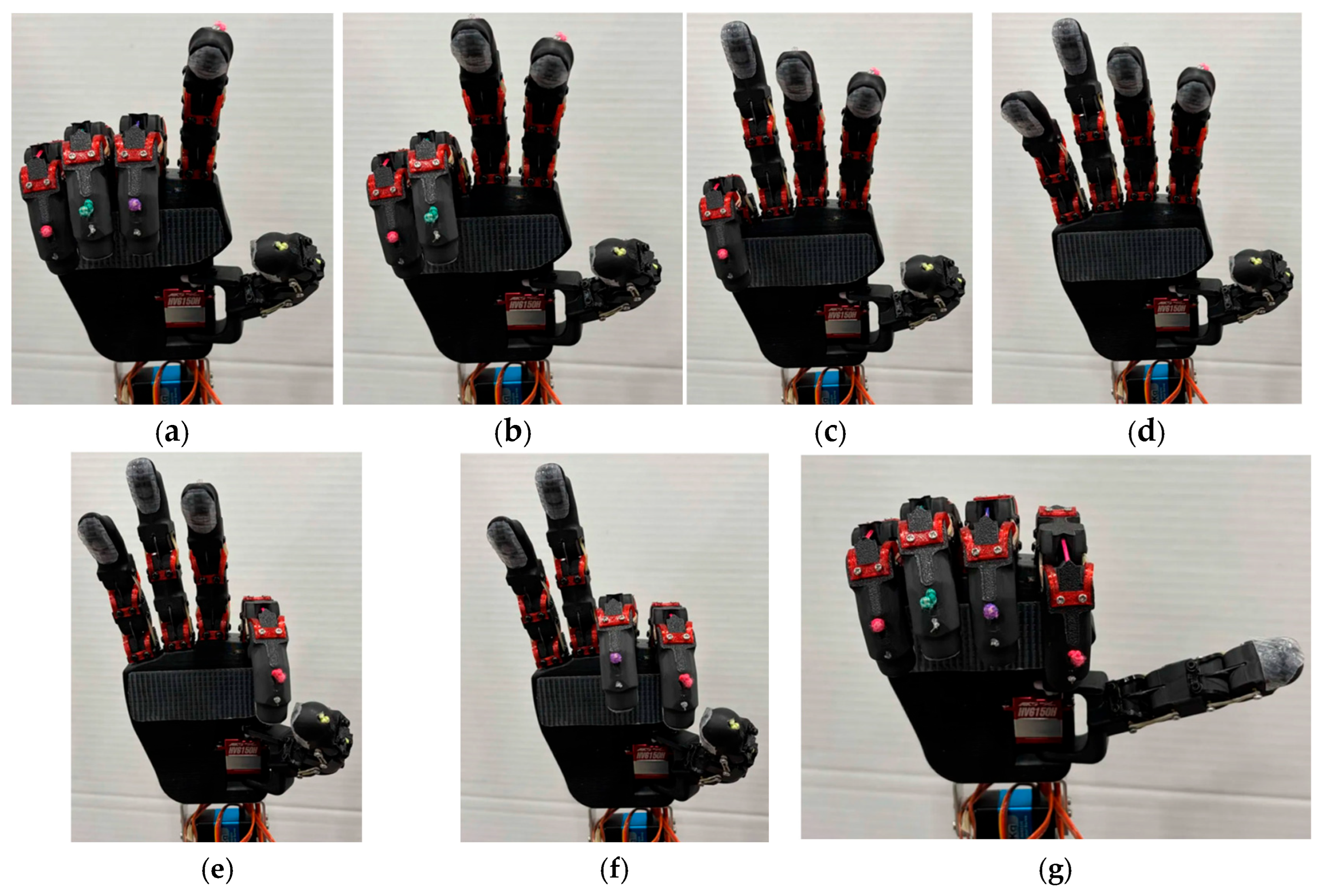
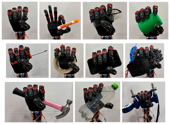
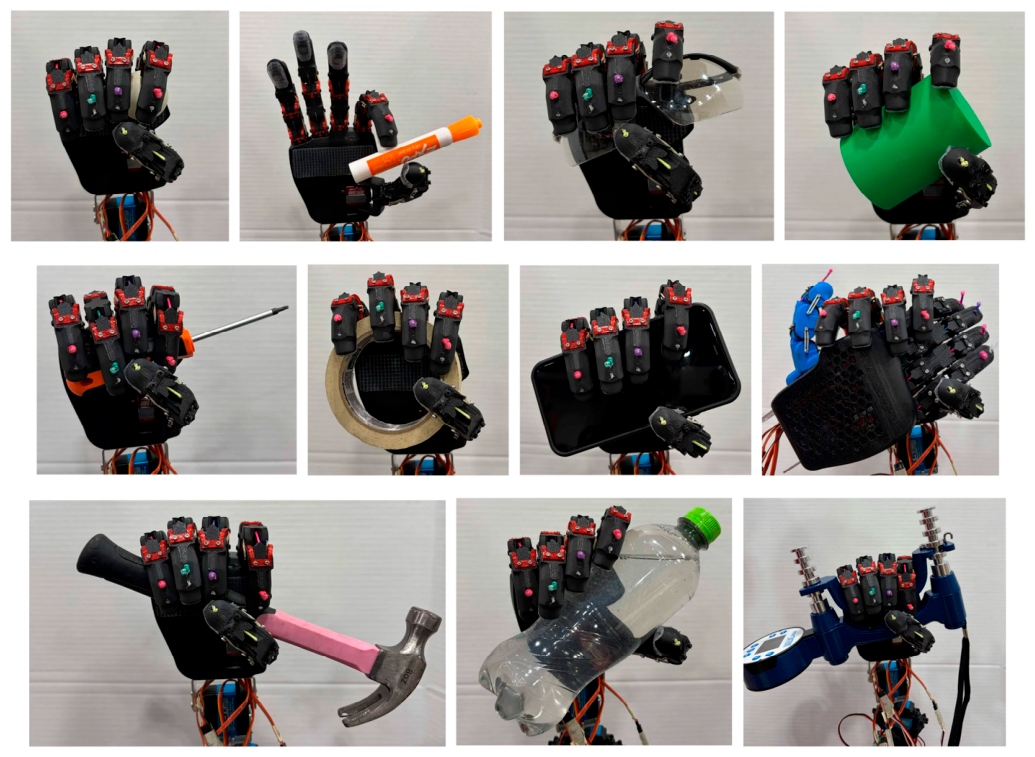
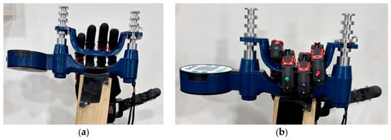
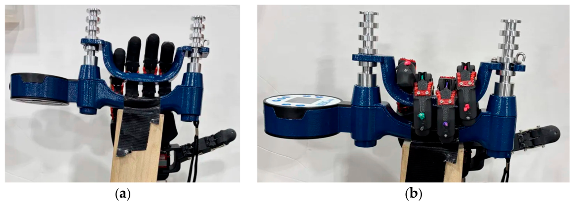
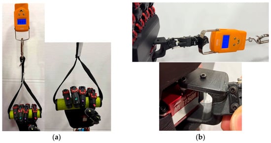
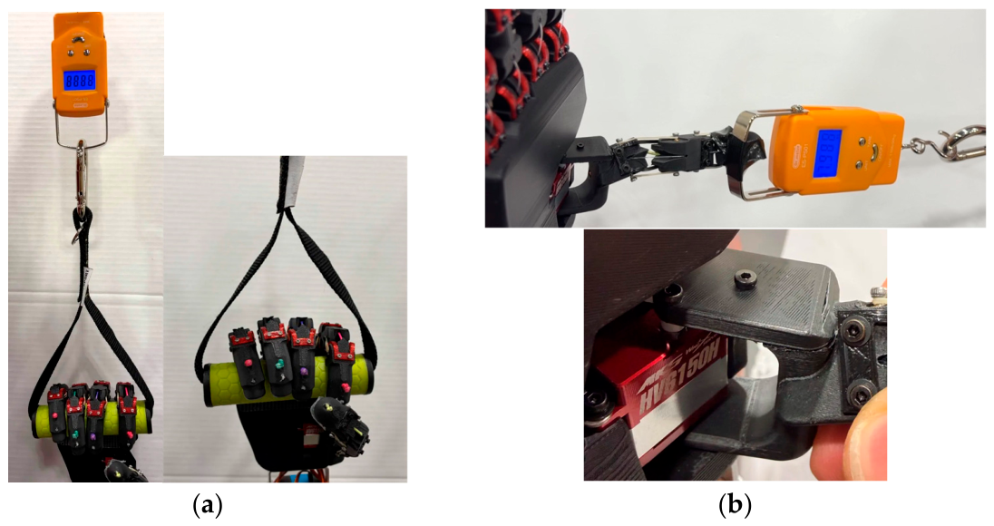
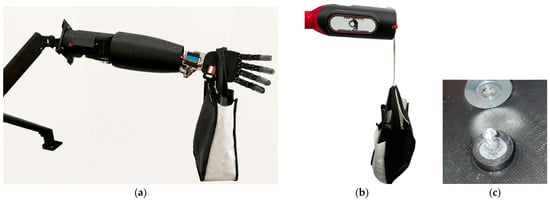
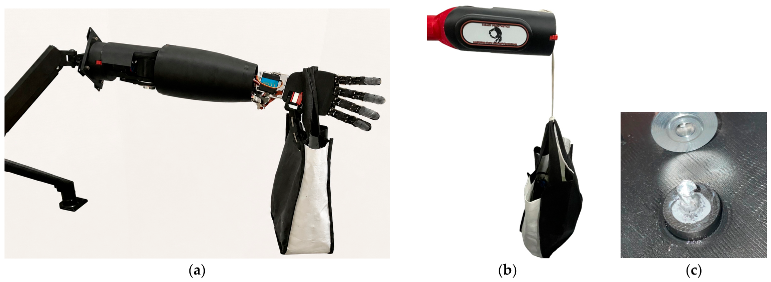

Disclaimer/Publisher’s Note: The statements, opinions and data contained in all publications are solely those of the individual author(s) and contributor(s) and not of MDPI and/or the editor(s). MDPI and/or the editor(s) disclaim responsibility for any injury to people or property resulting from any ideas, methods, instructions or products referred to in the content. |
© 2026 by the authors. Licensee MDPI, Basel, Switzerland. This article is an open access article distributed under the terms and conditions of the Creative Commons Attribution (CC BY) license.