Abstract
Precise global navigation satellite system (GNSS) positioning is based on carrier phase observations, where the understanding of the receiver antenna’s phase center corrections (PCCs) is critical. With the main goal of determining the PCC models of GNSS receiver antennas, only a few antenna calibration systems are in operation or under development worldwide. In this paper, a new automated GNSS receiver antenna calibration system, recently developed at the Laboratory for Measurements and Measuring Technique (LMMT) of the Faculty of Geodesy of the University of Zagreb in Croatia, is briefly presented. The developed system is an absolute field calibration system based on the utilization of a Mitsubishi MELFA RV-4FML-Q 6-axis industrial robot. The antenna’s PCC modeling is based on triple-difference carrier phase observations and spherical harmonic (SH) expansion. Our early calibration results for the global positioning system (GPS) L1 frequency show sub-millimeter agreements with the IGS approved Geo++ GmbH values.
1. Introduction
For high-accuracy global positioning applications on the centimeter and millimeter level, global navigation satellite system (GNSS) receivers are essential sensors. To obtain the required accuracy level, all influential factors and error sources must be understood and, in an appropriate manner, accounted for. One such important influence is the phase center correction (PCC) of GNSS receiver antennas.
Because of the antenna’s design characteristics and electromagnetic properties [1], the geometric location of the GNSS signal reception, i.e., the antenna phase center (PC), changes with respect to the incoming signal’s direction and frequency [2,3,4]. Such variations cause advances and delays in carrier phase observations and corresponding range errors. Therefore, receiver antenna calibration is needed.
Today, absolute filed calibration is the state of the art when it comes to GNSS receiver antenna calibration. Only a few calibration systems utilizing a precise robot are operational or under development worldwide [5,6,7,8,9,10,11,12], and even fewer are accredited by the International GNSS Service (IGS) to provide antenna calibration results [13]. Since this topic is of high interest to the scientific antenna community, and a new calibration system is highly desirable, at the Laboratory for Measurements and Measuring Technique (LMMT) of the Faculty of Geodesy of the University of Zagreb in Croatia, a new antenna calibration system has been developed [14].
In this article, preliminary antenna calibration results for the Global Positioning System (GPS) L1 frequency (G01) are presented and elaborated. Furthermore, the results on LMMT calibration validation with Geo++ GmbH are presented and discussed.
2. Materials and Methods
2.1. The Receiver Antenna Phase Center Correction Model
To fulfill the requirements of high-accuracy positioning applications, the receiver antenna PCCs must be determined. In line with the IGS convention, and as depicted in Figure 1, PCC is divided into the phase center offset (PCO) vector and the azimuth- and elevation-dependent phase center variation (PCV) [4,6,10,11,12,14]:
where is the line-of-sight unit vector from the receiver to the satellite i, and is the constant part equal in all directions present due to the relative characteristics of GNSS measurements [4,6]. The PCO is a vector from the antenna reference point (ARP) to an arbitrarily defined mean phase center (MPC). The PCV is the direction-dependent range correction function, i.e., the difference between the real and ideal phase wavefront. The PCCs, and all corresponding antenna-related points, vectors, and scalars, are defined in a 3D antenna-fixed left-handed coordinate system (antenna frame–AF).
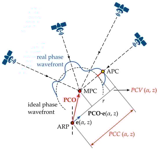
Figure 1.
Definition and geometrical interpretation of the adopted GNSS receiver antenna phase center correction (PCC) model; ARP—antenna reference point; MPC—mean phase center; APC—actual phase center; PCO—phase center offset; PCV—phase center variation.
A set of PCCs of an antenna are transformed to PCO and PCVs using a least squares (LSQ) adjustment and by simultaneously fulfilling two conditions. Firstly, the PCV at the antenna zenith are constrained to zero, i.e., zero-zenith constraint, by . Secondly, the PCO is determined such that the sum of the squared PCVs is minimal, i.e., .
2.2. Antenna Calibration Method at LMMT
To efficiently sample the entire antenna-under-test (AUT) hemisphere during calibration, at LMMT, a 6-axis industrial robot Mitsubishi MELFA RV-4FLM-Q is utilized. The robot turns the AUT in 2088 different antenna orientations, with stationary 2.5 s at every single orientation. Therefore, depending on the calibration timing parameters, a full calibration at LMMT lasts approx. 2 h. During calibration, a reference station (REF) on a 5 m short baseline is used. On both stations (REF and AUT), simultaneous 10 Hz raw carrier phase observations are registered with equal receiver settings. Afterwards, prior to PCC LSQ estimation, the carrier phase measurements are preprocessed to eliminate the majority of the GNSS error sources.
Generally, the calibration system at LMMT is based on the triple-difference (TD) approach, i.e., time-differenced double-difference carrier phase observations [15]. A generic GNSS observation equation from receiver A to satellite i, in units of length is expressed as follows [16]:
where is the geometric distance, is the speed of light, and are the receiver and satellite clock errors, is the relativistic effects term, is the combined satellite and receiver antennas’ PCC value, and are the receiver and satellite hardware delays, is the tropospheric delay, is the ionospheric delay, is the signal wavelength, is the integer phase ambiguity, is the carrier phase wind-up (PWU) effect, is the multipath term, and is the phase observation noise term.
Forming the TD carrier phase observations needed for antenna calibration includes eight raw observations, from Equation (2), on the REF (R) and AUT (T) receivers for two satellites i and j, in two epochs and :
By exploiting the high spatial and temporal correlations of GNSS observations, and by forming TDs on a short baseline between two time-adjacent AUT orientations, the final TDs contain only the AUT PCCs and the differential phase noise . At LMMT, the PCCs are parametrized by spherical harmonic (SH) expansion with a degree and order resolution of as follows:
where is the fully normalized Legendre function, and are the SH coefficients, and and are the azimuth and zenith angles in the AF.
The SH coefficients are determined by a constrained LSQ adjustment. Afterwards, the PCCs of the AUT are calculated for the entire antenna hemisphere according to Equation (4), transformed to PCO/PVC, and exported to the IGS ANTEX (ANTenna EXchange) format.
For an in-depth description of the antenna calibration methodology at LMMT, an interested reader is referred to Tupek et al. [14].
2.3. Antenna Calibration System at LMMT
The GNSS receiver antenna calibration system developed at LMMT consists of two major parts: hardware and software. Hardware-wise, the calibration system consists of a 6-axis industrial robot Mitsubishi MELFA RV-4FLM-Q with its corresponding controller Mitsubishi MELFA CR750, two GNSS receivers (Trimble NetR5) and antennas, and a personal computer. An on-site calibration set-up at LMMT is depicted in Figure 2. The in-house custom-made software components of the calibration system, all written in Python, are the antenna calibration module (ACM), time synchronization module (TISY), and the PCC estimation module. An in-depth description of the calibration system operation can be found in Tupek et al. [14].
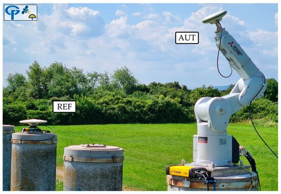
Figure 2.
GNSS antenna calibration system at the Laboratory for Measurements and Measuring Technique (LMMT) of the Faculty of Geodesy of the University of Zagreb in Croatia; REF—reference antenna (TRM57971.00 NONE); AUT—antenna-under-test (LEIAX1202GG NONE). The calibration field consists of two 5-m-spaced pillars, which are part of the Calibration Baseline of the Faculty of Geodesy of the University of Zagreb [17].
3. Results and Discussion
To test the antenna calibration system at LMMT and to validate the calibration results with Geo++ GmbH, an IGS approved calibration institution, from April to June of 2023, four calibration campaigns of the same GNSS antenna Trimble Zephyr 2 Geodetic (TRM57971.00 NONE, S/N: 30739001) for the GPS L1 frequency were conducted. Figure 3 visualizes the main benefit of using a robot for antenna calibration, i.e., a full coverage of the entire antenna hemisphere, even after only approx. 2 h of calibration.
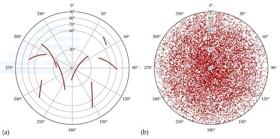
Figure 3.
Satellite azimuth and zenith angle plot (sky-plot) during antenna calibration at LMMT: (a) topocentric frame (TF); (b) antenna frame (AF).
To validate the LMMT antenna calibration results, a comparison with an independent calibration was conducted. For that purpose, the investigated antenna was calibrated individually by Geo++ GmbH, an IGS approved institution, on 5 August 2022.
According to the new calibration method at LMMT, PCCs have been estimated for every conducted antenna calibration campaign. Lastly, to obtain a final solution, calibration results have been averaged, and the final PCO and PVC grids were exported to ANTEX. Table 1 summarizes the LMMT and Geo++ GmbH estimated PCOs. The PCO differences between the LMMT and Geo++ GmbH calibrations are on the sub-millimeter level. The PCVs of the investigated antenna for the GPS L1 frequency, per calibration institution, are depicted in Figure 4. Both individual calibration results show similar PCV behaviors over the entire antenna hemisphere, with noticeable larger values at the antenna horizon for the Geo++ calibrations. Also, for both calibration results (LMMT and Geo++ GmbH), small azimuthal variations are noticeable.

Table 1.
PCO vector components of antenna TRM57971.00 NONE (S/N: 30739001) of GPS L1 (G01) frequency per calibration institution. All values are in millimeters (mm).
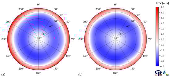
Figure 4.
(a) Geo++ GmbH and (b) LMMT phase center variations (PCVs) of antenna TRM57971.00 NONE (S/N: 30739001) for GPS L1 (G01) frequency.
To estimate the accuracy of LMMT individual antenna calibration results, the Geo++ GmbH calibration results are taken as reference values. The PCC differences of antenna TRM57971.00 NONE (S/N: 30739001) for GPS L1 (G01) frequency, over the entire antenna hemisphere, are calculated, and they are depicted in Figure 5. By a simple visualization of the gained difference pattern, it is evident that values around zero prevail with larger values mainly located at low antenna elevations, e.g., for an azimuth of approx. 300°.
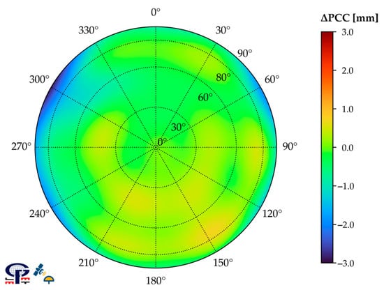
Figure 5.
Geo++ GmbH and LMMT PCC differences () of antenna TRM57971.00 NONE (S/N: 30739001) for GPS L1 (G01) frequency after transformation to common PCO and datum.
To obtain a quantitative accuracy estimation of LMMT calibration results, the following scalar measures of the PCC difference pattern are calculated: minimum and maximum , root-mean-square (RMS) deviation of , range of the , and the interquartile range (IQR) of the . All calculated values are given in Table 2. Furthermore, because during the majority of GNSS applications, a standard elevation mask of a minimum of 10° is used, a 10° elevation-reduced antenna hemisphere analysis is justified. All accuracy measures were determined accordingly and are given in Table 2.
Table 2.
Quantitative measures of the difference between Geo++ GmbH’s and LMMT’s individual absolute calibrations: minimum, maximum, root-mean-square (RMS) deviation, range, and interquartile range of . All values are in millimeters (mm).
Considering the full antenna hemisphere, the LMMT and Geo++ GmbH PCC differences are in the interval from −2.92 to 0.72 mm, with the middle 50% of being within 0.44 mm. The RMS of the differences is 0.52 mm. However, if only the elevation-reduced antenna hemisphere is considered, accuracy measures significantly improve. The range of all is 2.36 mm with an RMS value of 0.34 mm whereby the middle 50% of the differences does not exceed 0.41 mm.
Therefore, to summarize, with the newly developed LMMT antenna calibration system, an estimated agreement with the accredited Geo++ GmbH calibrations, within 0.52 mm, was achieved.
4. Conclusions
The new GNSS receiver antenna calibration system developed at the Laboratory for Measurements and Measuring Technique (LMMT) of the Faculty of Geodesy of the University of Zagreb in Croatia can provide meaningful antenna calibration results for the GPS L1 frequency. According to the obtained experimental research results regarding the Trimble Zephyr 2 Geodetic antenna, an estimated agreement within 0.52 mm, in terms of RMS, with the accredited Geo++ GmbH results, was achieved. Therefore, our calibration results also confirm the compatibility of LMMT GPS L1 calibrations with the IGS accredited Geo++ GmbH calibrations.
Author Contributions
Conceptualization, A.T., M.Z., M.Š. and Đ.B.; methodology, A.T., M.Z. and M.Š.; software, A.T.; validation, A.T. and M.Z.; formal analysis, A.T. and M.Z.; investigation, A.T.; resources, A.T. and M.Z.; data curation, A.T.; writing—original draft preparation, A.T.; writing—review and editing, M.Z., M.Š. and Đ.B.; visualization, A.T.; supervision, M.Z.; project administration, A.T.; funding acquisition, M.Z. All authors have read and agreed to the published version of the manuscript.
Funding
This research was funded by the University of Zagreb under the research project “Automatization of measurement procedure in the Laboratory for Measurements and Measuring Technique of the Faculty of Geodesy”.
Institutional Review Board Statement
Not applicable.
Informed Consent Statement
Not applicable.
Data Availability Statement
The data presented in this study are available on request from the corresponding author.
Acknowledgments
The authors would like to express their gratitude to the following: the Inea Group, the local Mitsubishi Electric authorized distributor, for great support regarding robotic automatization; the State Geodetic Administration of the Republic of Croatia for providing the GNSS equipment used for this research; Nenad Smolčak of Geomatika-Smolčak Ltd. for his many useful receiver-specific advices; Krunoslav Špoljar for his technical and logistical assistance during calibration field activities; and Sergej Baričević for his help during the production of antenna-robot mounting elements.
Conflicts of Interest
The authors declare no conflict of interest.
References
- Maqsood, M.; Gao, S.; Montenbruck, O. Antennas. In Springer Handbook of Global Navigation Satellite Systems; Teunissen, J.G.P., Montenbruck, O., Eds.; Springer International Publishing: Cham, Switzerland, 2017; pp. 505–534. [Google Scholar]
- Wübbena, G.; Schmitz, M.; Menge, F.; Seeber, G.; Völksen, C. A New Approach for Field Calibration of Absolute GPS Antenna Phase Center Variations. Navigation 1997, 44, 247–255. [Google Scholar] [CrossRef]
- Wübbena, G.; Schmitz, M.; Menge, F.; Böder, V.; Seeber, G. Automated Absolute Field Calibration of GPS Antennas in Real-Time. In Proceedings of the 13th International Technical Meeting of the Satellite Division of The Institute of Navigation (ION GPS 2000), Salt Lake City, UT, USA, 19–22 September 2000; The Institute of Navigation: Manassas, VA, USA, 2000; pp. 2512–2522. [Google Scholar]
- Kröger, J.; Kersten, T.; Breva, Y.; Schön, S. Multi-Frequency Multi-GNSS Receiver Antenna Calibration at IfE: Concept-Calibration Results-Validation. Adv. Space Res. 2021, 68, 4932–4947. [Google Scholar] [CrossRef]
- Wübbena, G.; Schmitz, M.; Warneke, A. Geo++ Absolute Multi-Frequency GNSS Antenna Calibration. In Proceedings of the EUREF Analysis Centres Workshop, Warsaw, Poland, 16–17 October 2019. [Google Scholar]
- Kröger, J.; Kersten, T.; Breva, Y.; Schön, S. Multi-GNSS Receiver Antenna Calibration. In Proceedings of the FIG Working Week 2020, International Federation of Surveyors, Amsterdam, The Netherlands, 10–14 May 2020; pp. 1–13. [Google Scholar]
- Riddell, A.; Moore, M.; Hu, G. Geoscience Australia’s GNSS Antenna Calibration Facility: Initial Results. In Proceedings of the International GNSS Society Symposium (IGNSS 2015), Gold Coast, QLD, Australia, 16–17 July 2015; pp. 1–12. [Google Scholar]
- Bilich, A.; Erickson, B.; Geoghegan, C. 6-Axis Robot for Absolute Antenna Calibration at the US National Geodetic Survey. In Proceedings of the IGS Workshop 2018, International GNSS Service, Wuhan, China, 29 October–2 November 2018; International GNSS Service: Pasadena, CA, USA, 2018. [Google Scholar]
- Hu, Z.; Cai, H.; Jiao, W.; Zhou, R.; Zhai, Q.; Liu, X.; Kan, H.; Zhao, Q. Preliminary Results of IGMAS BDS/GNSS Absolute Antenna Phase Center Field Calibration. In Proceedings of the China Satellite Navigation Conference (CSNC 2022), Beijing, China, 22–25 May 2022; Yang, C., Xie, J., Eds.; Springer: Singapore, 2022; pp. 147–160. [Google Scholar]
- Willi, D.; Lutz, S.; Brockmann, E.; Rothacher, M. Absolute Field Calibration for Multi-GNSS Receiver Antennas at ETH Zurich. GPS Solut. 2020, 24, 28. [Google Scholar] [CrossRef]
- Sutyagin, I.; Tatarnikov, D. Absolute Robotic GNSS Antenna Calibrations in Open Field Environment. GPS Solut. 2020, 24, 92. [Google Scholar] [CrossRef]
- Dawidowicz, K.; Rapiński, J.; Śmieja, M.; Wielgosz, P.; Kwaśniak, D.; Jarmołowski, W.; Grzegory, T.; Tomaszewski, D.; Janicka, J.; Gołaszewski, P.; et al. Preliminary Results of an Astri/UWM EGNSS Receiver Antenna Calibration Facility. Sensors 2021, 21, 4639. [Google Scholar] [CrossRef] [PubMed]
- IGS Antenna Working Group. Available online: https://igs.org/wg/antenna/#files (accessed on 1 August 2023).
- Tupek, A.; Zrinjski, M.; Švaco, M.; Barković, Đ. GNSS Receiver Antenna Absolute Field Calibration System Development: Testing and Preliminary Results. Remote Sens. 2023, 15, 4622. [Google Scholar] [CrossRef]
- Hauschild, A. Combinations of Observations. In Springer Handbook of Global Navigation Satellite Systems; Teunissen, J.G.P., Montenbruck, O., Eds.; Springer International Publishing: Cham, Switzerland, 2017; pp. 583–604. [Google Scholar]
- Hauschild, A. Basic Observation Equations. In Springer Handbook of Global Navigation Satellite Systems; Teunissen, J.G.P., Montenbruck, O., Eds.; Springer International Publishing: Cham, Switzerland, 2017; pp. 561–582. [Google Scholar]
- Zrinjski, M.; Barković, Đ.; Špoljar, K. Review of Precise Calibration Methods of Geodetic Calibration Baselines. Geod. List. 2022, 76, 25–52. [Google Scholar]
Disclaimer/Publisher’s Note: The statements, opinions and data contained in all publications are solely those of the individual author(s) and contributor(s) and not of MDPI and/or the editor(s). MDPI and/or the editor(s) disclaim responsibility for any injury to people or property resulting from any ideas, methods, instructions or products referred to in the content. |
© 2023 by the authors. Licensee MDPI, Basel, Switzerland. This article is an open access article distributed under the terms and conditions of the Creative Commons Attribution (CC BY) license (https://creativecommons.org/licenses/by/4.0/).