Abstract
This article investigates the influence of planet mounting position on axle loads in double planet planetary gear trains. The study includes basic information about the type of geartrain used, theoretical data, finite element analysis simulations, and empirical experiments to provide more detailed data on the impact of planet pin position on bearing loads in different scenarios. A test model with six different setups is designed for the studies. Finite element simulations were then conducted to examine the model and to give more comprehensive information on the effect of pin location. Empirical experiments were conducted on a test rig to verify the theoretical and simulation results. The results indicate that the position of the planet pins has an impact on the distribution of load between the bearings of the outer and inner planets of the gear train. This study aims to provide more insights into the design and optimization of planetary gear trains when evaluating the loads on the bearings of the planet gears.
1. Introduction
Planetary gears are a highly versatile and efficient gear system that has become critical in many industrial applications, especially in the transport and automotive industry, electricity generation, etc. They are valued for their ability to handle high torque loads and transmit power in a compact and lightweight design. As well as provide multiple gear ratios in a limited space allowing for improved performance and increased efficiency. Often used in hybrid and electric vehicles to combine the power of electric motors and internal combustion engines, in the gearbox system of wind turbines and in transmissions and differential systems to transmit power.
1.1. Comparison between Positive and Negative 2k-H Planetary Gear Train
The double-planet planetary gear train is a planetary gear system with pairs of planet gears mounted on a common carrier. The inner planet meshes with the sun gear, the outer planet meshes with the ring gear, and the pair of planet gears mesh. A common abbreviation used for this kind of gear system is 2k-H positive [1,2], 2k-H type D [3] or [4] gear train. A comparison between the double planet planetary gear train and the most widely recognisable planetary gear trains, the 2k-H, can be seen in Figure 1.
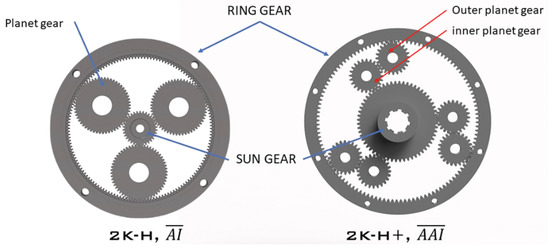
Figure 1.
Comparison between negative and positive 2k-H planetary gear train.
The use of a second row of planets leads to a variety of consequences. Most notably, the direction of rotation of the ring gear is reversed compared to the single row 2k-H and the direction of rotation of the carrier Figure 2. This makes the internal gear ratio i0 positive—the carrier and the ring gear rotate in the same direction, which explains why this gear type is referred to as a positive planetary gear train [1,2,4].
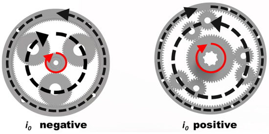
Figure 2.
Comparison of the kinematics of negative and positive 2k-H planetary gear train.
Another notable difference between the two arrangements is the torque distribution. In the case of the negative 2k-H, the carrier is a summation shaft which can be described by the following equation:
where TH is the torque of the carrier, TS torque of the sun gear and TR torque of the ring gear. In the case of the double planet positive gear train, the ring gear is the summation shaft, and the torque distribution is as follows:
TH = −(Ts + TR),
TR = −(Ts + TH);
TR = TS × i0.
This can also be expressed using the modified Wolf symbol [4]. The double line represents the summation shaft in Figure 3.
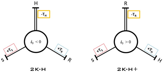
Figure 3.
Modified wolf symbol showing the differences in torque distribution between positive and negative 2k-H planetary gear train.
A more detailed comparison between different planetary and power branching geartrain types can be found in [5].
1.2. Load on Planet Axels
Planetary gear trains are far more complicated regarding stress calculation and load prediction than other gear systems. Splitting the input power between several branching components—planets- enables high torque capacity in compact packages. On the other hand, in practice, ideal manufacturing accuracy and assembly are unachievable, which, combined with other factors, results in a difference in the load sharing of the planets. More on load sharing in double-planet planetary gear trains can be found in [6,7].
While most studies focus on load-sharing factors between the planets, an interesting phenomenon was observed during the tests with full planet engagement planetary geartrain described in [8]. There was a noticeable difference in loading not only between the pairs but also between the outer and inner rows of planets, with a repeatable pattern showing elevated stress on the outer row. This led to the hypothesis that the load distribution might be affected by the location and angle relation between the planet axes. This study will examine this concept for the 2k-H + geartrain since its design is closest to the full planet engagement from [8].
The hypothesis will be tested in the following manner.
- FEA simulation.
- Empirical experiments with a test rig.
2. Experimental Evaluation
2.1. Load on Planet Axels
All studies will be based on the same model, redesigning the gear train used in [8]. Since all the components and measuring equipment are readily available. It comprises a module 2 sun gear 60 teeth with profile shift x = −0.417. Two planet gears with 24 teeth each. And different ring gears depending on the set-up. Six test scenarios are considered in the study with different angles between the planet axles, as shown in Figure 4.
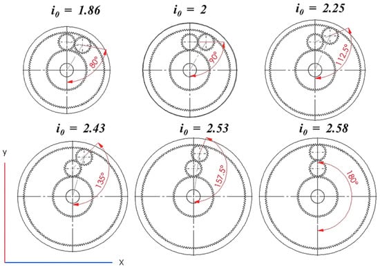
Figure 4.
Diagram of the tested gear trains.
2.2. FEA Simulation
For CAD simulation, assemblies of all six scenarios were created. Gears are modelled with the dimensions and tolerances corresponding to the physical gears from the test rig. The planet gears are modelled together with the pins. The type of simulation is linear static with the following conditions:
- The ring gear is fixed;
- Sun gear and planet gear pins have hinged fixtures with a degree of freedom—rotation around the central axis;
- Torque is applied to the sun gear. All studies are done with 50 Nm of torque with a direction as shown in Figure 5;
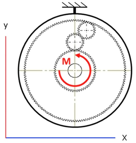 Figure 5. The direction of applied torque and fixed element in the tests.
 - Material with properties corresponding to c45 steel used in the physical gears is used for the sun gear and planet gears. ABS plastic is used for the ring gears since the physical experiment is conducted with 3d printed ring gears from ABS plastic;
- Equivalent stress is measured with a probe on the selected face of the pin where the strain gauges of the physical model would measure Figure 6. All other stresses in the models are ignored.
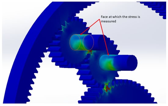 Figure 6. Location at which the stresses are considered in the FEA simulation.
2.3. Empirical Experiments
As mentioned before, the physical experiments are done with a redesigned version of the test rig used in [8]. A special component with the locations of all pins is used in place of the carrier. Sections of ring gears are 3D printed and used for different scenarios. The experiments are static. A lever with calibrated weight is used to apply 50 Nm of torque to the sun gear. The ring gear is fixed to achieve the same conditions shown in Figure 5. The model of the test rig can be seen in Figure 7.
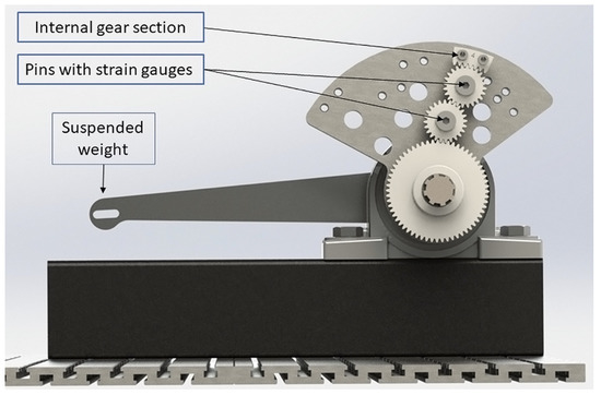
Figure 7.
3D model of the test rig.
Stress is measured via strain gauges mounted on planet pins (Figure 8). Four strain gauges in each pin are mounted in a double half-bridge configuration [9]. Measured data is then converted to MPa values for bending with the methodology described in [8].
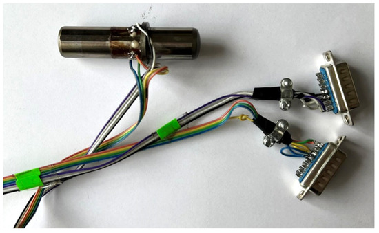
Figure 8.
An actual pin with strain gauges from the test equipment.
3. Results
The results from the FEA simulations can be seen in Table 1.

Table 1.
Stress results from the FEA simulation.
Pi describes the MPa value on the inner planet, while Po the value of the outer planet. A slight difference in stress between the various positions is observed. The outermost planet is more loaded with smaller angle values, and the inner is more loaded with higher angle values. The Values shown are an average of 5 simulations for each scenario. A chart representation of the results is depicted in Figure 9.
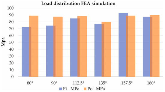
Figure 9.
Chart comparison from the FEA simulation.
The results from the physical experiments with the test rig are shown in Table 2.
Table 2.
Stress results from the empirical experiment.
A slightly more prominent difference can be observed in the physical tests. What is also worth mentioning is that the stress values are significantly lower than the FEA simulation with the same input torque. This can be accounted to several factors. First, the FEA simulation assumes infinitely rigid fixtures, which differs significantly from the physical model. The FEA simulation is linear [10], which means that the software assumes a linear relationship between the stress and strain regardless of the material’s resultant stress and yield point. Again, this differs from reality, especially with 3D-printed ABS plastic. Some of the stresses and deformations are absorbed by other less stiff components and materials of the test rig. There are clearances of manufacturing inaccuracies [11] and uneven load distribution [12] in parts which the software doesn’t account for. And finally, there is friction and efficiency loss in the test rig, which affects the magnitude of the input torque. However, the pattern of load distribution has similarities with the FEA simulations. A chart representation of the results can be seen in Figure 10.
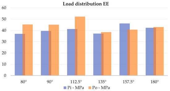
Figure 10.
Chart comparison from the empirical experiment.
The following Figure 11, Figure 12 and Figure 13 compare the results for each scenario from both CAD and empirical experiments. Because of the differences in stress and force values, the data is shown as a percentage ratio between loads of the planet pins—Pi for the inner planet and Po for the outer planet.
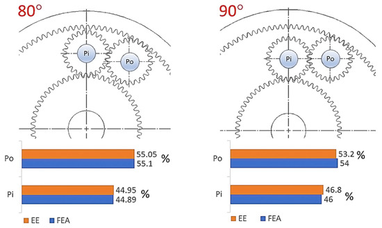
Figure 11.
Percentage comparison of pin loads between CAD simulation and empirical experiment for 80 and 90 degrees.
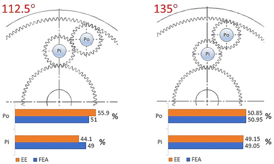
Figure 12.
Percentage comparison of pin loads between CAD simulation and empirical experiment for 112.5 and 135 degrees.
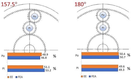
Figure 13.
Percentage comparison of pin loads between CAD simulation and empirical experiment for 157.5 and 180 degrees.
4. Conclusions
The results from both the CAD simulation and empirical experiments indicated that the position of the planet pins has an impact on the distribution of load between the pins of the outer and inner planets of the gear train. Despite the significant stress value differences between the two types of experiments, the trend and percentage load ratio are very similar. The empirical experiments show a slightly more uneven distribution, specifically on a 112.5-degree angle. Also, it can be noted that the stress increases in value with a larger angle. This can be explained by the change in gear ratio when using a larger ring gear. Since the torque distribution in 2k-H + ()geartrain is as according to Equations (2) and (3) and the input torque and shaft being the same for all experiments, the torque in the carrier holding the planet axes, increases with the increase of the gear ratio i0.
In conclusion, the difference in loading between the inner and outer pins is insignificant, especially when compared to the full planet engagement planetary gear train, where a more prominent difference between the planet pins is observed. It is worth noting that both the CAD and empirical simulations are done in static conditions. A future experiment in a dynamic state with the same ratio i0 but a different number of teeth in the planets can further clarify the topic. Ultimately it is up to the designer to consider the difference in loading when calculating the bearings and other components of the gear train.
Author Contributions
Conceptualization, V.I.; methodology, V.I.; validation, A.A.; formal analysis, A.A. All authors have read and agreed to the published version of the manuscript.
Funding
This research was funded by the Research and Development Sector at the Technical University of Sofia.
Institutional Review Board Statement
Not applicable.
Informed Consent Statement
Not applicable.
Data Availability Statement
The data presented in this study are available on request from the corresponding author. The data are not publicly available due to privacy restrictions.
Conflicts of Interest
The authors declare no conflict of interest.
References
- Muller, H.W. Epicyclic Drive Trains; Wayne State University Press: Detroit, MI, USA, 1982. [Google Scholar]
- Looman, J. Zahnradgetriebe–Grundlagen, Konstruktion, Andwendung in Fahrzeugen, Auflage; Springer: Berlin, Germany, 1996. [Google Scholar]
- Kudryavtsev, V.; Kirdyashev, Y. Planetary Gear Trains; Mashinostroenie: Leningrad, Russia, 1977. (In Russian) [Google Scholar]
- Arnaudov, K.; Karaivanov, D. Planetary Gear Trains; LAP LAMBERT Academic Publishing: Beau Basin, Mauritius, 2017. (In Bulgarian) [Google Scholar]
- Alexandrov, A. A Research and comparative analysis of the full planet engagement planetary gear train. Proc. Tech. Univ. Sofia 2022, 72, 37–42. [Google Scholar] [CrossRef]
- Liu, W.; Li, J.; Kang, Y.; Liu, Y.; Xu, X.; Dong, P. Load Sharing Behavior of Double-Pinion Planetary Gear Sets Considering Manufacturing Errors. IOP Conf. Ser. Mater. Sci. Eng. 2019, 677, 052068. [Google Scholar] [CrossRef]
- Avinash, S. Influence of Planetary Needle Bearings on the Performance of Single and Double Pinion Planetary Systems. J. Mech. Des. 2007, 129, 85–94. [Google Scholar]
- Ivanov, V.; Alexandrov, A.; Tsonev, V.; Kuzmanov, N.; Troha, S.; Dimitrov, L. The effect of external forces on the load sharing of a full planet engagement planetary gear train. In Proceedings of the International Conference on Communications, Information, Electronic and Energy Systems (CIEES), Veliko Tarnovo, Bulgaria, 24–26 November 2022; pp. 1–6. [Google Scholar] [CrossRef]
- Ştefănescu, D.M. Handbook of Force Transducers—Principles and Components; Springer: Berlin/Heidelberg, Germany, 2011; ISBN 978-3-642-18295-2. [Google Scholar]
- Kythe, P.; Dongming, W.; Okrouhlík, M. An Introduction to Linear and Nonlinear Finite Element Analysis: A Computational Approach. Appl. Mech. Rev.–Appl. Mech. Rev. 2004, 57, B25. [Google Scholar] [CrossRef]
- Bodas, A.; Kahraman, A. Influence of Carrier and Gear Manufacturing Errors on the Static Load Sharing Behavior of Planetary Gear Sets. JSME Int. J. 2004, 47, 908–915. [Google Scholar] [CrossRef]
- Arnaudov, K.; Karaivanov, D.; Dimitrov, L. Some practical problems of distribution and equalization of internal loads in planetary gear trains. Mech. Mach. Sci. 2013, 13, 585–596. [Google Scholar]


Disclaimer/Publisher’s Note: The statements, opinions and data contained in all publications are solely those of the individual author(s) and contributor(s) and not of MDPI and/or the editor(s). MDPI and/or the editor(s) disclaim responsibility for any injury to people or property resulting from any ideas, methods, instructions or products referred to in the content. |
© 2023 by the authors. Licensee MDPI, Basel, Switzerland. This article is an open access article distributed under the terms and conditions of the Creative Commons Attribution (CC BY) license (https://creativecommons.org/licenses/by/4.0/).