1. Introduction
The increasing demand for sustainable solutions in aviation has led to intensive research into new drive systems for regional aircraft. One of the solutions to decarbonize the aviation industry is to use cryogenic hydrogen to replace fossil fuels. However, hydrogen being very flammable and explosive, the accumulation of potentially threating concentrations of hydrogen must be avoided under any conditions. A critical aspect of the design and operation of these aircraft is the management of liquid hydrogen as a fuel source. Hydrogen tanks are used to store and supply hydrogen for efficient hybrid flight operations. Among others, the EU-funded TheMa4HERA project is looking into such solutions. It is carrying out more detailed research into the on-board thermal management of a hybrid-electric energy and propulsion system in regional aircraft. These new solutions pose challenges, for example, regarding safety, which is a prerequisite for the introduction of hydrogen-powered aircraft. Understanding the airflow dynamics in the event of a leakage from a liquid hydrogen tank is essential for ensuring safety and operational reliability. As early as 1997, it was established in [
1] that hydrogen aircraft are no more dangerous than conventional airplanes, and many risks can be mitigated through appropriate measures. Current designs foresee placing the hydrogen tank outside the pressurized area in the aircraft tail, which in flight already excludes an overflow from the tank into the cabin section of the fuselage. Thus, in an emergency, a slow release of hydrogen can be counteracted with proper ventilation so that there is no major risk of ignition [
2,
3]. This is because hydrogen is the lightest element, so it volatilizes quickly as it rises. Outflow of cabin air and dedicated leakage paths could ensure the ventilation of the area around the tank to exclude any buildup of dangerous hydrogen levels mixed with air in flight. However, on the ground, a forced ventilation system will be required to ensure the ventilation around the hydrogen tank. This ventilation must dilute potential leakages from the tank (e.g., due to diffusion or defects) such that the gaseous hydrogen/air mixture does not approach flammability at any location around the tank. Hydrogen is more susceptible to explosions and fires due to a wide flammability range of 4–75 Vol.-% [
3]. Therefore, it is important to keep the hydrogen concentration under control and to establish a 1% threshold. At concentrations above 1%, there is an increased risk of ignition.
This paper is part of the TheMa4HERA project and presents a comprehensive simulation study on possible leakage scenarios in a hydrogen tank in the rear area of a regional aircraft in ground operating condition. By using a zonal simulation model, the behavior of hydrogen in the event of a leak is to be analyzed, and the effects on safety and the performance of the fan for venting are to be evaluated. The results of this study will contribute to the development of safer and more efficient hybrid aircraft.
2. Simulation Method and Modeling
The simulation method and the simulation model created are described in more detail below. This is followed by the boundary conditions and procedure for the simulative parameter study.
2.1. Simulation Method
The modeling of the unpressurized area is based on the Velocity Propagating Zonal Model (VEPZO) [
4] developed at Fraunhofer. A three-dimensional grid is applied over the interior space, dividing the compartment into small volumes, referred to as zones. Each zone is connected to its neighboring zones, which are in air exchange with each other. Using the existing geometry of the interior, a model can be generated automatically [
5]. This approach allows for the examination of the effects of the location and intensity of sinks and sources, such as thermal loads, air flow openings, or (harmful) gases/substances, on the indoor air quality and climate. Additionally, insights into the local distribution of temperatures and substance concentrations within the compartment can be obtained. In the VEPZO model, thermal models for the enclosure are coupled to integrate the heat flow through the envelope surface. In previous works, the zonal modeling approach has been validated for the cabin of a business jet and for a train carriage [
6,
7].
The rear area of a regional aircraft is to be simulated with a volume of the compartment of 22.1 m
3. The tank has a volume of 10.6 m
3.
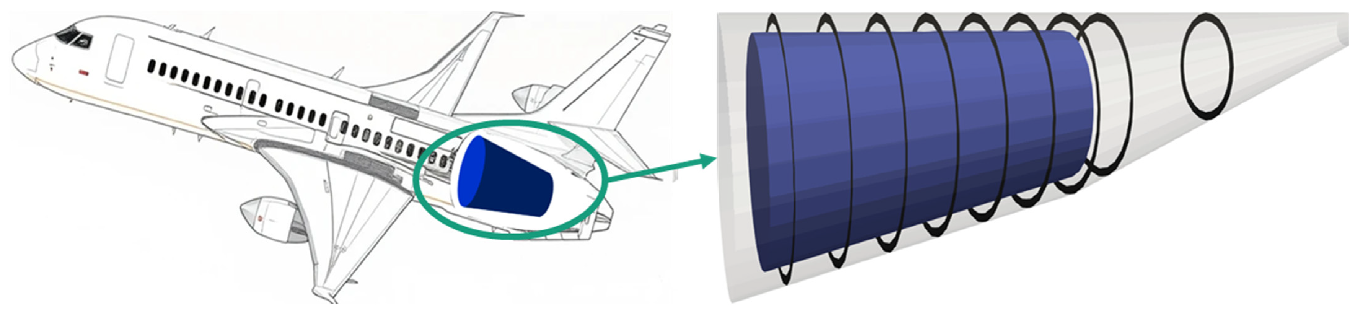
Figure 1 shows the position of the unpressurized compartment in a hybrid-electric regional aircraft and the geometry of the compartment including the tank.
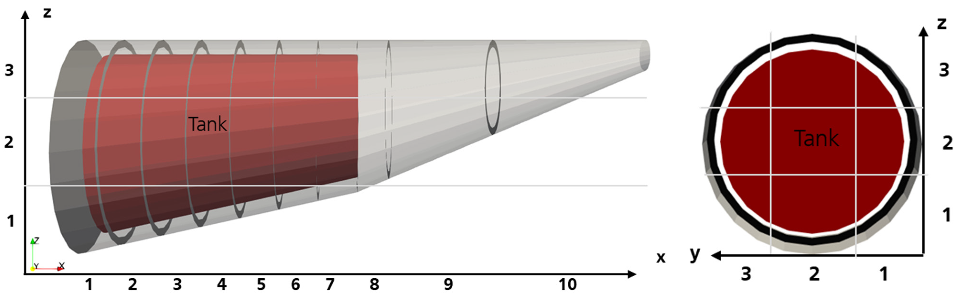
The model consists of three parts. The front and rear sections correspond to the air volume in front of and behind the tank, while the middle section represents the air volume around the tank. The cross-sectional areas for the air exchange between the tank and the skin are considered here. For this, the cross-sectional area through the 10 cm thick frames must be subtracted. This leads to a zonal model with 105 zones in total. In the x-direction, there are 13 zones; in the y-direction, there are three zones; and in the z-direction, there are also three zones. The gridding of the zonal model of the tank compartment is shown in
Figure 2. The exact dimensions of the zones are depicted in
Table 1.
The described zonal model is used to simulate the air flow pattern in the compartment to predict the hydrogen concentrations after the gas escapes from the tank.
2.2. Simulation-Based Parameter Study
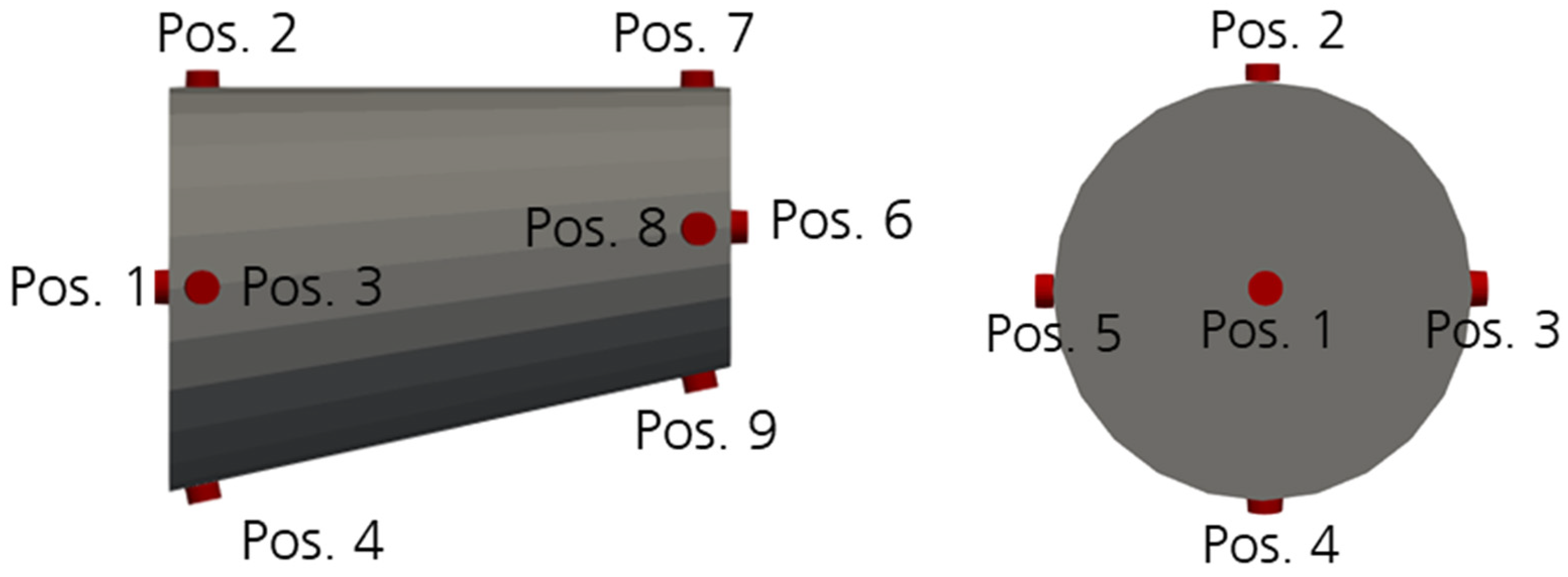
In the parameter study, variations in the leakage position, position of the supply and exhaust air openings and the mass flow of the fan are investigated. Ten possible leakage positions are considered, which are shown in
Figure 3. The leakage positions are assigned to the following zones in the model (see
Table 2).
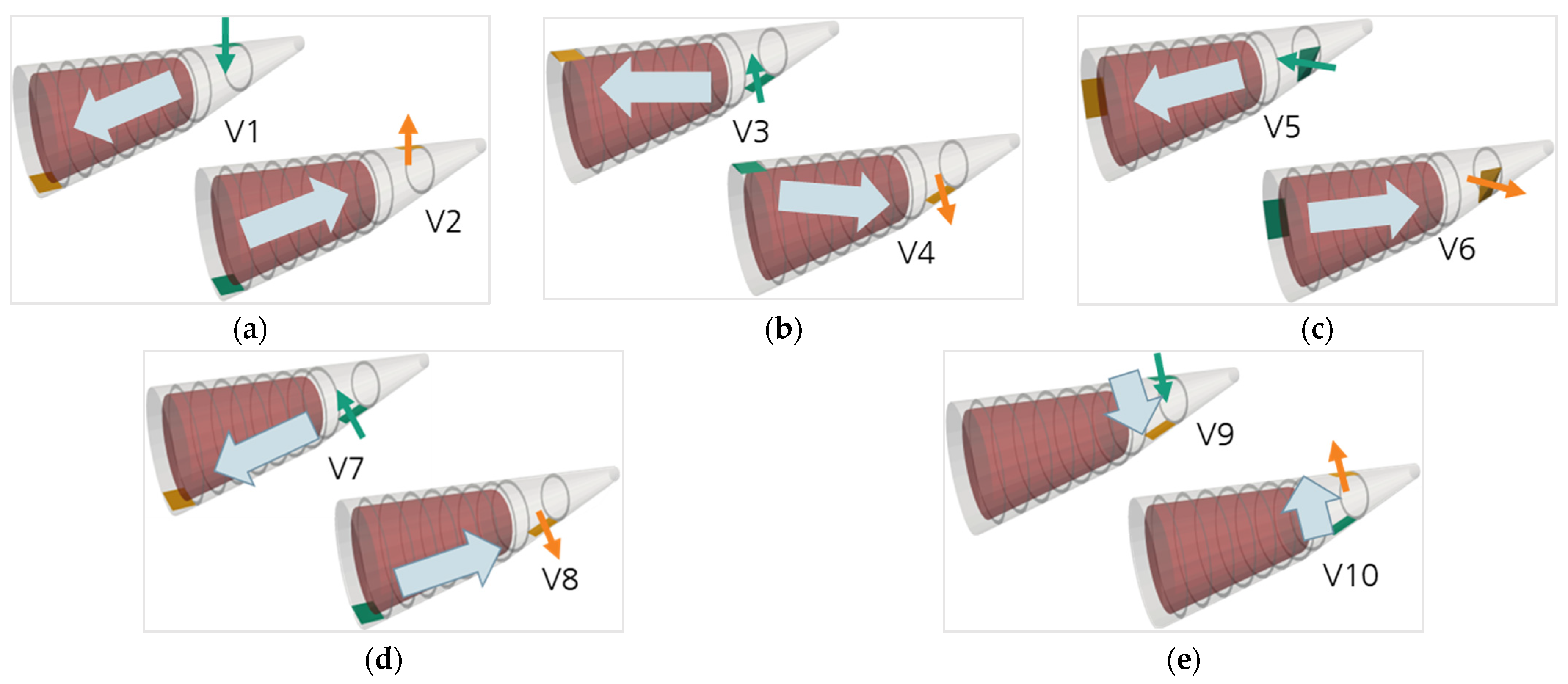
In addition, ten different settings for the supply and exhaust air and the fan are examined. Due to space constraints, the fan will be placed in the area behind the tank in all scenarios. In variants V1 to V6, these are aligned in opposite directions. In contrast, the other variants have both openings positioned on the bottom (V7 and V8) or rear area (V9 and V10) of the compartment. The simulated variants are depicted in
Figure 4. The fan is used either for air intake (turquoise arrow) or extraction (orange arrow). The big arrows indicate the expected overall air flow direction.
The thermal conditions of the system are characterized by an outside temperature on the ground of 15 °C (standard day of International Standard Atmosphere (ISA)). The tank envelope is highly insulated, ensuring minimal heat transfer. In contrast, the fuselage is not insulated, resulting in a surface temperature that approximates the outside temperature. The ventilation system is designed with one inlet and one outlet valve; thus, the inlet temperature is equal to the outlet temperature. This configuration allows simple air circulation within the compartment. Additionally, the system is equipped with a fan that operates at a constant power level and ensures a consistent airflow of 2700 m
3/h. This corresponds to the volume flow of a fan for the unpressurized area currently under development within the project TheMa4HERA. The leakage rate of the tank is assumed to be 0.333 L per hour and results from oral communication with hydrogen tank-related project members at the EASN conference 2024 [
8]. This represents emissions in the case of a leakage volume flow of 0.333 L/h. This value corresponds approximately to the hydrogen limit leakage rate for hydrogen-powered vehicles of 5 cm
3/min (0.3 L/h). This is normatively defined in DIN EN IEC 62282-2-100 [
9].
2.3. Data Analysis
The simulated hydrogen distribution in the compartment forms the basis for data evaluation. On one hand, the maximum concentration values are analyzed, and different variants are compared. On the other hand, the pressure losses along the most likely path of the gas within the compartment are examined. The pressure loss due to individual resistances such as bends, valves, constrictions, etc., is calculated as follows with reference to the dynamic pressure of the flowing fluids (1) [
10]:
The used is the resistance coefficient. The resistance coefficient indicates the extent to which the flow is disturbed and the resulting pressure and energy loss. depends on the geometry and shape of the resistance, as well as the flow regime.
3. Results
First, the maximum hydrogen concentrations are analyzed, and then the pressure drop through the flow path is calculated. This allows for the identification of the variant that can most efficiently remove hydrogen and determines the pressure loss for the fan.
3.1. Distribution of H2 Concentration
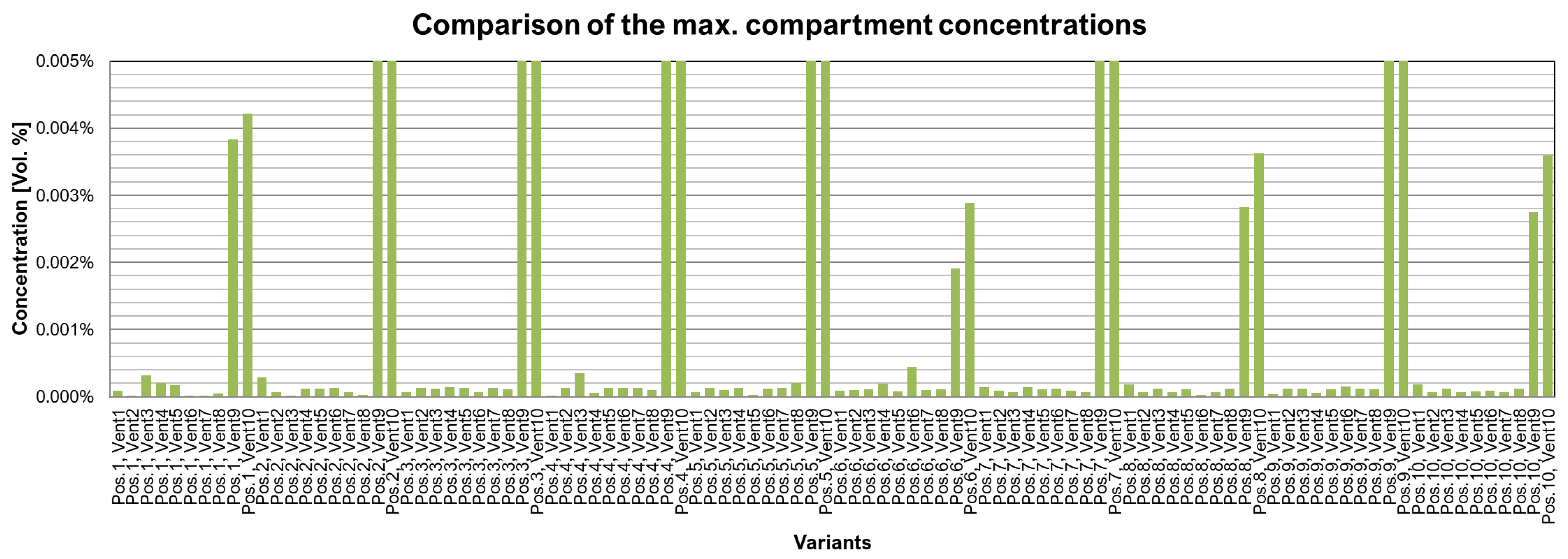
In order to compare the different variants, the maximum H
2 concentrations in the compartment of the different ventilation and leakage scenarios are used. The simulation results are depicted in the diagram in
Figure 5.
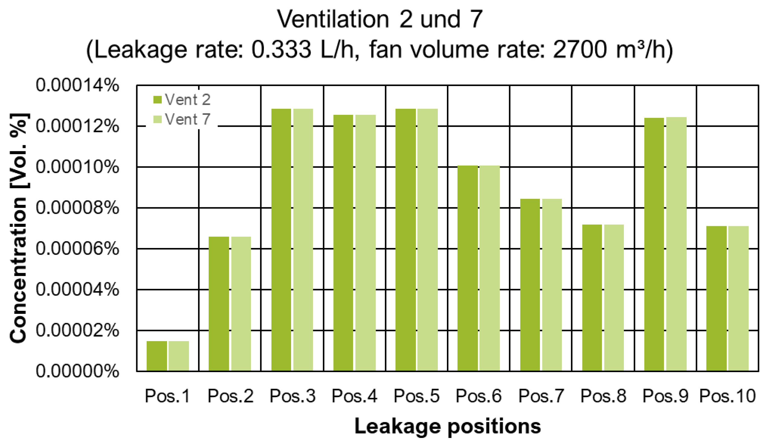
The diagram shows that variants 9 and 10 generate short-circuit ventilation and are unable to dissipate the hydrogen sufficiently in all areas of the compartment. Variants 1, 3 and 6 also show increased concentrations in the event of leakage at particular locations of the tank. Based on all possible leakage positions, variants 2 and 7 provide the best compartment ventilation. In this case, the various leakage positions result in different maximum concentrations. This is illustrated in
Figure 6. This yields a maximum concentration of 0.0001% with a fan volume flow of 2700 m
3/h.
3.2. Pressure Drop Due to Flow Path
Fan sizing requires an estimation of the pressure loss through the flow path. For this, the most probable path that the air takes through the compartment is determined. To do this, it is assumed that the greater the mass flow over a certain area, the higher the probability. The pressure loss per section is proportional to the square of the flow velocity in that segment, according to Equation (1). Without knowing the resistance coefficient, conclusions about the pressure loss of the individual segments can be drawn based on the flow velocity. Therefore, the equation for dynamic pressure (0.5 ×
× v
2) is calculated for each section. For this hypothesis, the inlet and outlet size are assumed to be an area of 10 cm × 20 cm (0.02 m
2). Details of the pressure drop (ventilation 2) calculation are shown in
Table 3.
The significantly higher flow velocities at the inlet and outlet into the compartment lead to substantially higher pressure losses than the flow in the compartment. The flow losses in this area are therefore negligible. This clearly demonstrates that the major design parameter for the fan will be the pressure drop in the inlet and outlet opening to minimize the resistance coefficient.
4. Conclusions and Discussion
The study investigates the critical issue of hydrogen leakage from a liquid hydrogen tank in the rear section of a hybrid-electric regional aircraft. The primary objective of the research is to determine the necessary air volume flows that a fan must provide to keep hydrogen concentrations below 1% by volume in the event of a leak. Additionally, the research aims to identify the optimal fan position for effective hydrogen removal.
To achieve this, the geometry of the hydrogen tank and its surrounding unpressurized area is reconstructed. A zonal simulation model is used to replicate the airflow patterns within the compartment. The model serves as the basis for a comprehensive parameter study, in which various fan configurations and leakage scenarios are simulated. The results show the maximum hydrogen concentrations for different ventilation variants and highlight that certain configurations, particularly variants 9 and 10, are unable to sufficiently dissipate hydrogen in all areas. In contrast, variants 2 and 7 demonstrate the best performance, achieving a maximum concentration of 0.0001%. This ensures a significant safety margin.
Furthermore, the study analyzes the pressure losses along the airflow path and concludes that the inlet and outlet openings are critical design parameters for minimizing resistance and optimizing fan performance. Overall, the findings provide valuable insights into the safe management of hydrogen as a fuel source in hybrid-electric aircraft and support the development of safer and more efficient aviation technologies.
Author Contributions
Conceptualization, C.M. and V.N.; methodology, C.M. and V.N.; validation, C.M. and V.N.; formal analysis, C.M.; investigation, C.M.; resources, C.M.; data curation, C.M.; writing—original draft preparation, C.M.; writing—review and editing, V.N.; visualization, C.M.; supervision, V.N.; project administration, V.N.; funding acquisition, V.N. All authors have read and agreed to the published version of the manuscript.
Funding
The presented project has received funding from the TheMa4HERA joint undertaking under grant agreement No. 101102008. The funders had no role in the design of the study, in the collection, analyses, or interpretation of data, or in the writing of the manuscript.
Institutional Review Board Statement
Not applicable.
Informed Consent Statement
Not applicable.
Data Availability Statement
The data presented in this study are available on request from the corresponding author.
Acknowledgments
We would like to thank Collins Aerospace and Leonardo for their cooperation in this study and their technical support.
Conflicts of Interest
The authors declare no conflicts of interest.
Abbreviations
The following abbreviations are used in this manuscript:
| ISA | International Standard Atmosphere |
| VEPZO | Velocity Propagating Zonal Model |
References
- Schmidtchen, U.; Behrend, E.; Pohl, H.-W.; Rostek, N. Hydrogen aircraft and airport safety. Renew. Sustain. Energy Rev. 1997, 1, 239–269. [Google Scholar] [CrossRef] [Scilit]
- Khandelwal, B.; Karakurt, A.; Sekaran, P.R.; Sethi, V.; Singh, R. Hydrogen powered aircraft: The future of air transport. Prog. Aerosp. Sci. 2013, 60, 45–59. [Google Scholar] [CrossRef] [Scilit]
- Dadashzadeh, M.; Kashkarov, S.; Makarov, D.; Molkov, V. Risk assessment methodology for onboard hydrogen storage. Int. J. Hydrogen Energy 2018, 43, 6462–6475. [Google Scholar] [CrossRef] [Scilit]
- Norrefeldt, V.; Grün, G.; Sedlbauer, K. VEPZO—Velocity propagating zonal model for the estimation of the airflow pattern and temperature distribution in a confined space. Build. Environ. 2012, 48, 183–194. [Google Scholar] [CrossRef] [Scilit]
- Pathak, A.; Norrefeldt, V.; Lemouedda, A.; Grün, G. The Modelica Thermal Model Generation Tool for Automated Creation of a Coupled Airflow, Radiation Model and Wall Model in Modelica. In Linköping Electronic Conference Proceedings; Linköping University Electronic Press: Linköping, Sweden, 2014; pp. 115–124. [Google Scholar]
- Will, H.; Stratbücker, S.; Norrefeldt, V.; Reith, A.; Scherer, C. Risikoeinschätzung zur Ansteckungsgefahr mit COVID-19 im Schienenpersonen-Sowie im Straßenpersonennah-und-Fernverkehr; Deutsches Zentrum für Schienenverkehrsforschung beim Eisenbahn-Bundesamt: Dresden, Germany, 2021. [Google Scholar]
- Norrefeldt, V.; Pathak, A.; Lemouedda, A.; Siede, M.; Grün, G. Validation of the zonal thermal model VEPZO/RADZO for cold outside conditions on a business jet mock-up. In Proceedings of the AST 2025 Conference, Hamburg, Germany, 24–25 February 2025. [Google Scholar]
- Dreossi, G.; Horvat, A.B. Permeation Investigation of Carbon Fibre Reinforced Polymer Material for LH2 Storage Thermally Shocked and Mechanically Cycled at Cryogenic Temperature. Aerospace 2025, 12, 342. [Google Scholar] [CrossRef] [Scilit]
- IEC 62282-2-100:2020; DIN EN IEC 62282-2-100 VDE 0130-2-100:2021-04. Brennstoffzellentechnologien: Teil 2-100: Brennstoffzellenmodule-Sicherheit; VDE Verlag GMBH: Berlin, Germany, 2021.
- Taschenbuch für Heizung und Klimatechnik: Einschließlich Warmwasser-und Kältetechnik, 73rd ed.; Oldenbourg: München, Germany, 2007.
| Disclaimer/Publisher’s Note: The statements, opinions and data contained in all publications are solely those of the individual author(s) and contributor(s) and not of MDPI and/or the editor(s). MDPI and/or the editor(s) disclaim responsibility for any injury to people or property resulting from any ideas, methods, instructions or products referred to in the content. |